

Page 1
Deutsch English Français
IZAR RECEIVER
M-Bus
Einbauanleitung
Installation guide
Guide d‘installation
Diese
Anleitung ist
dem Endkunden
auszuhändigen.
This guide must
be given to the end
consumer.
Ce guide doit être
donné au client
nal.
Page 2
IZAR RECEIVER M-Bus
I
80 mm
120 mm
II
OK
Deutsch English Français
60 mm
60 mm
4
2
- 2 -
Page 3
Deutsch English Français
III
IV
IZAR RECEIVER M-Bus
29 30 31 32 33 34
68
M-Bus
USB/LAN
RS232/Rep
Modem
Rx/Tx
66 67
1 2 3 4 5 6
65 16
IZAR
CENTER 250
Memory
- 3 -
Page 4

IZAR RECEIVER M-Bus
Deutsch
English Français
1. Allgemeines zur Anleitung
Die Anleitung wendet sich an ausgebildetes Fachpersonal.
Grundlegende Arbeitsschritte sind deshalb nicht aufge-
führt.
2. Verpackungsinhalt
Kontrollieren Sie bitte vor der Montage bzw. Inbetriebnahme des IZAR RECEIVER M-Bus den Verpackungsinhalt.
IZAR RECEIVER M-Bus
Wandhalter
2 Befestigungsschrauben
2 Kunststoffplomben
3. Beschreibung
Der IZAR RECEIVER M-Bus empfängt Funktelegramme
von IZAR RADIO oder Open Metering Zählern und speichert diese in seinem internen Speicher ab. Jedes Mal
wenn ein neues Telegramm empfangen wird, löscht der
IZAR RECEIVER M-Bus das alte Telegramm dieses Zählers.
Der IZAR RECEIVER M-Bus kann nur in Kombination mit
einen IZAR CENTER M-Bus Master genutzt werden.
Es ist, wie mit einem normalen M-Bus Zähler, eine automatische, intervallgesteuerte Auslesung möglich.
Die im IZAR CENTER gespeicherten Daten können anschließend zur IZAR@NET Software übertragen werden.
- 4 -
Page 5
Deutsch
English Français
IZAR RECEIVER M-Bus
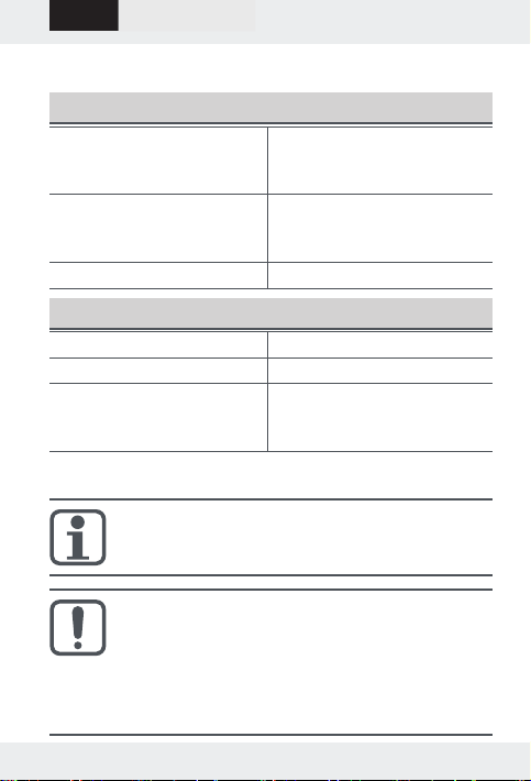
4. Technische Daten
Allgemein
Spannungsversorgung
(via M-Bus)
U = 32 V … 42 V
Imax = 30 mA (20 M-Bus
Lasten)
Gehäuse 120 x 120 x 35 mm Kunst-
stoffgehäuse für Wandmontage (interne Antenne)
Gewicht ca. 200 g
Umgebung
Schutzklasse IP 20
Betriebstemperaturbereich 0 °C … +60 °C
Luftfeuchtigkeit 10 % … 70 % relative
Luftfeuchtigkeit, nicht
kondensierend
5. Hinweise
Der IZAR RECEIVER M-Bus darf nur von Fach-
kräften montiert und in Betrieb genommen werden.
Für die Installation müssen geeignete präventive
Maßnahmen zum EMV-Schutz getroffen werden.
Bitte stellen Sie sicher, dass die M-Bus Spannung - abhängig von der Kabellänge (Widerstand und
Impedanz) niemals weniger als 32 V beträgt, um den
IZAR RECEIVER M-Bus betreiben zu können.
- 5 -
Page 6
IZAR RECEIVER M-Bus
Der IZAR RECEIVER M-Bus benötigt in etwa so
viel M-Bus Strom wie 20 normale M-Bus Endgeräte.
Daher können maximal:
1 IZAR RECEIVER M-Bus an einen IZAR CENTER 25
3 IZAR RECEIVER M-Bus an einen IZAR / HYDRO-
CENTER 60
6 IZAR RECEIVER M-Bus an einen IZAR CENTER 120
12 IZAR RECEIVER M-Bus an einen IZAR / HYDRO-
CENTER 250
angeschlossen werden.
Der IZAR RECEIVER M-Bus kann nicht mit HYD-
RO-CENTER 25 Geräten betrieben werden.
Die maximale Kabellänge ist auf 100 m ... 1 km
begrenzt, abhängig von der Anzahl angeschlossener IZAR RECEIVER M-Bus und anderer M-Bus
Geräte.
Deutsch
English Français
Zur Inbetriebnahme des IZAR RECEIVER M-Bus
- 6 -
stellen Sie bitte sicher, dass Sie die neueste Version der Diehl Metering IZAR@CENTER Software
einsetzen.
Page 7
Deutsch
English Français
IZAR RECEIVER M-Bus
6. Montage / Demontage
Der IZAR RECEIVER M-Bus muss mindestens
10 cm entfernt von metallischen Gegenständen
(Rohre, Kabel) installiert werden.
Die Installationsumgebung muss den Schutzbedingungen
des Gehäuses (IP20) entsprechen.
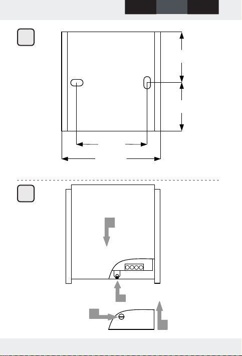
6.1 Wandhalter montieren
Die Wandhalterung muss an einer geraden und
achen Wand montiert werden.
Der Sitz muss gerade sein.
Befestigen Sie die Wandhalterung lagerichtig mittels
der beiden Schrauben an einer Wand (Maße siehe
Abb. I).
6.2 IZAR RECEIVER M-Bus montieren (Abb. II)
1. Setzen sie den IZAR RECEIVER M-Bus auf den Wand-
halter auf und drücken Sie ihn nach unten bis die
Verriegelung einrastet.
2. Schieben Sie die Abdeckkappe für die Anschlüsse von
unten in die vorgesehen Aussparung.
3. Verriegeln Sie die Abdeckkappe mit einer der beige-
legten Kunststoff-Plomben.
- 7 -
Page 8
IZAR RECEIVER M-Bus
Deutsch
English Français
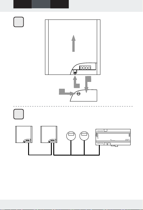
6.3 IZAR RECEIVER M-Bus demontieren
(Abb. III)
1. Verdrehen Sie die Kunststoff-Plombe mit einem
Schraubendreher bis Sie zerbricht.
2. Die Abdeckkappe für die Anschlüsse nach unten auf-
schieben.
3. Heben Sie die Verriegelung an, um den IZAR RECEI-
VER M-Bus nach oben zu schieben und vom Wandhalter abzunehmen.
7. Elektrischer Anschluss
Für den elektrischen Anschluss des IZAR
RECEIVER M-Bus muss die Abdeckkappe abgenommen werden.
Klemme Wert Beschreibung
1 M-Bus Eingang
Polarität 1
2 M-Bus Eingang
Polarität 2
3 M-Bus Ausgang
Polarität 1
4 M-Bus Ausgang
Polarität 2
Anschlussbeispiel siehe Abb. IV.
Zwei-Draht Leitung von
einem IZAR / HYDROCENTER (Polarität egal).
M-Bus Zwei-Draht Leitung zum nächsten Gerät
(wenn noch weitere Geräte am gleichen M-Bus
angeschlossen werden
sollen).
- 8 -
Page 9
Deutsch
English Français
IZAR RECEIVER M-Bus
8. Anzeigeelemente
Eine rote und eine grüne LED neben den elektrischen Anschlüssen des IZAR RECEIVER M-Bus zeigen die jeweiligen Betriebszustände an.
Anzeige Betriebszustand
Die rote LED leuchtet
Start
einmal für weniger als
3 Sekunden auf.
Die grüne LED leuchtet
einmal kurz auf.
Betrieb
Ein gültiges Funktelegramm
wurde empfangen.
Die rote LED leuchtet
nach dem Start permanent.
Hardware Fehler
In diesem Fall ist die Selbst-
überprüfung gescheitert und
der IZAR RECEIVER M-Bus
muss ausgetauscht werden.
Beide LEDs blinken
abwechselnd mit einer
Firmware Update wird durch-
geführt.
Frequenz von etwa
1 Hz.
9. Wartung
IZAR RECEIVER M-Bus benötigt keine besondere Wartung.
Nicht mit Lösungsmitteln oder Scheuermittel reinigen, da
diese das Kunststoffgehäuse beschädigen können.
Wenn nötig, Tuch oder feuchten Schwamm zur Reinigung
verwenden.
- 9 -
Page 10

IZAR RECEIVER M-Bus
Deutsch
English Français
10. Umwelthinweis
Das Gerät darf nicht mit dem Hausmüll entsorgt werden.
Senden Sie es zum Recycling an den Hersteller zürück.
11. Konformitätserklärung
Die vollständige EG-Konformitätserklärung kann unter
http://www.diehl.com/de/diehl-metering/produkte-
loesungen/produkt-download/
abgerufen werden.
Bitte wählen Sie dort den Partner "Diehl Metering GmbH"
und den Produktbereich "Systemtechnik" aus.
- 10 -
Page 11

Deutsch
English
Français
IZAR RECEIVER M-Bus
1. General information on the guide
The guide is intended for trained specialised personnel.
For this reason no basic working steps are included.
2. Package content
Please check the package content before you install or
use the IZAR RECEIVER M-Bus for the rst time.
IZAR RECEIVER M-Bus
Wall bracket
2 fastening screws
2 plastic seals
3. Description
The IZAR RECEIVER M-Bus receives radio telegrams from
the IZAR RADIO or Open Metering meters and saves
them in the internal memory. Each time a new telegram
is received, the IZAR RECEIVER M-Bus deletes the old telegram of this meter.
The IZAR RECEIVER M-Bus can only be used in combination with a IZAR CENTER M-Bus Master.
An automatic, interval-controlled reading is possible as
with a normal M-Bus meter.
The data saved in the IZAR CENTER can then be transmitted to the IZAR@NET software.
- 11 -
Page 12
IZAR RECEIVER M-Bus
Deutsch
English
Français
4. Technical data
General
Power supply (via M-Bus) U = 32 V … 42 V
Imax = 30 mA (20 M-Bus
loads)
Housing 120 x 120 x 35 mm plastic
housing for wall mounting
(internal antenna)
Weight approx. 200 g
Environment
Protection class IP 20
Operating temperature
0 °C … +60 °C
range
Relative humidity 10 % … 70 % relative hu-
midity, non-condensing
5. Instructions
The IZAR RECEIVER M-Bus should be mounted
and put into operation by qualied experts only.
When installing suitable preventive measures for
EMC protection must be met.
Please ensure that the M-Bus voltage - depending on the cable length (resistance and impedance) is never below 32 V, in order to operate the
IZAR RECEIVER M-Bus.
- 12 -
Page 13
Deutsch
The IZAR RECEIVER M-Bus requires around the
same amount of M-Bus current as 20 normal
M-Bus terminal equipment.
Therefore a maximum of:
1 IZAR RECEIVER M-Bus to a IZAR CENTER 25
3 IZAR RECEIVER M-Bus to a IZAR / HYDRO-CENTER 60
6 IZAR RECEIVER M-Bus to a IZAR CENTER 120
12 IZAR RECEIVER M-Bus to a IZAR / HYDRO-CENTER 250
can be connected.
The IZAR RECEIVER M-Bus can not be operated
with HYDRO-CENTER 25 devices.
The maximum cable length is limited to 100 m ...
1 km depending on the number of connected
IZAR RECEIVER M-Bus and other M-Bus devices.
Please ensure for the initial operation of the
IZAR RECEIVER M-Bus that the most recent version of the Diehl Metering IZAR@CENTER software is used.
English
Français
IZAR RECEIVER M-Bus
- 13 -
Page 14
IZAR RECEIVER M-Bus
Deutsch
English
Français
6. Installation / removal
The IZAR RECEIVER M-Bus must be installed at
least 10 cm away of metallic objects (pipes, ca-
ble).
The installation environment has to correspond to the
protective conditions of the housing (IP20).
6.1 Install wall bracket
The wall bracket must be evenly mounted on a
straight and at wall.
The installation position must be straight.
Use the two screws to properly attach the wall brack-
et to a wall (measures see Fig. I)
6.2 Install IZAR RECEIVER M-Bus(Abb. II)
1. Put the IZAR RECEIVER M-Bus onto the wall bracket
and push it downwards till it locks.
2. Slide the cover for the connections from bottom into
the provided recess.
3. Lock the cover with the supplied plastic seal.
6.3 Remove IZAR RECEIVER M-Bus (g. III)
1. Turn the plastic seal with a screwdriver till it breaks.
2. Slide the cover for the connections to the bottom.
3. Lift the locking in order to slide the IZAR RECEIVER
M-Bus upwards and to remove it from the wall bracket.
- 14 -
Page 15
Deutsch
English
Français
IZAR RECEIVER M-Bus
7. Electrical connection
The cover cap for the electric connection of the
IZAR RECEIVER M-Bus must be removed.
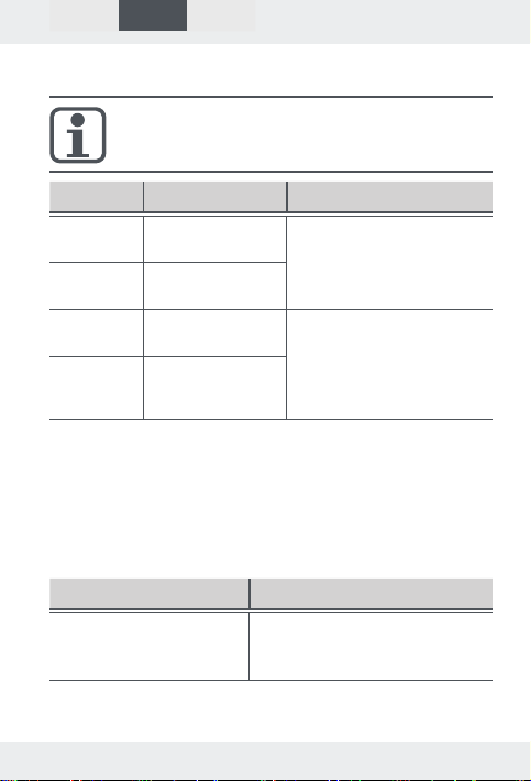
Terminal Value Description
1 M-Bus input
polarity 1
2 M-Bus input
Two-wire connection
IZAR / HYDRO-CENTER
(polarity irrelevant).
polarity 2
3 M-Bus output
polarity 1
4 M-Bus output
polarity 2
M-Bus two-wire connection to the next device
(if further devices are
to be connected to the
same M-Bus).
Connection example see g. IV.
8. Display elements
A red and green LED next to the electric connections of
the IZAR RECEIVER M-Bus show the corresponding operational conditions.
Display Operational condition
The red LED illuminates
once for less than 3
seconds.
Start
- 15 -
Page 16
IZAR RECEIVER M-Bus
Deutsch
English
Français
Display Operational condition
The green LED ashes
briey.
Operation
A valid radio telegram was
received.
The red LED illuminates
continuously after start.
Hardware fault
In this case, the self-test has
failed and the IZAR RECEIVER M-Bus has to be replaced.
Both LEDs ash alternately with a frequency
The rmware update is
performed.
of approx. 1 Hz.
9. Maintenance
IZAR RECEIVER M-Bus does not require any special maintenance. Do not use solvents or abrasive cleaning agents,
as these may damage the plastic housing.
If required, use a cloth or moist sponge for cleaning.
10. Environmental note
The device must not be disposed together with the domestic waste. Return it to the manufacturer for recycling.
11. Declaration of Conformity
The full declaration of conformity is available at
http://www.diehl.com/en/diehl-metering/products-
solutions/product-download/
Please select the partner "Diehl Metering GmbH" and the
product area "Metering Systems".
- 16 -
Page 17

Deutsch English
Français
IZAR RECEIVER M-Bus
1. Généralités sur le mode d’emploi
Ce guide s’adresse au personnel spécialisé et qualié.
Les étapes de travail fondamentales n’y sont donc pas
mentionnées.
2. Contenu de l’emballage
Contrôlez le contenu de l’emballage avant le montage ou
la mise en service de IZAR RECEIVER M-Bus.
IZAR RECEIVER M-Bus
Support mural
2 Vis de xation
2 Joint en plastique
3. Description
L’IZAR RECEIVER M-Bus reçoit les radiotélégrammes
de l’IZAR RADIO ou compteurs Open Metering (système de mesure ouvert) et les enregistre dans sa mémoire interne. Si un nouveau radiotélégramme arrive,
l’IZAR RECEIVER M-Bus efface le radiotélégramme précédent de ce compteur.
L’IZAR RECEIVER M-Bus ne peut être utilisé qu’en combinaison avec l’IZAR CENTER M-Bus Master.
Une lecture automatique et commandée par intervalle est
possible comme avec un compteur M-Bus régulier.
Les données mémorisées dans l’IZAR CENTER peuvent
être transmises par la suite au logiciel IZAR@NET.
- 17 -
Page 18
IZAR RECEIVER M-Bus
Deutsch English
Français
4. Caractéristiques techniques
Généralités
Alimentation électrique
(via M-Bus)
U = 32 V … 42 V
Imax = 30 mA (20 charges
M-Bus)
Boîtier 120 x 120 x 35 mm boîtier
en plastique pour support
mural (antenne interne)
Poids env. 200 g
Environnement
Classe de protection IP 20
Plage des températures
0 °C … +60 °C
de service
L'humidité de l'air 10 % … 70 % l'humidité re-
lative de l'air, sans condensation
5. Indications
Seul un personnel qualié est autorisé à installer
ou à mettre en service l'IZAR RECEIVER M-Bus.
- 18 -
Page 19
Deutsch English
Des mesures préventives appropriées à la pro-
tection CEM doivent êtres appliquées pour l'installation.
Veuillez vous assurer que le courant M-Bus - en fonction
de la longueur de câble (résistance et impédance) - n'est
jamais inférieur à 32 V, pour pouvoir mettre en service
l'IZAR RECEIVER M-Bus.
La consommation du courant M-Bus de
l'IZAR RECEIVER M-Bus est presque la même
que la consommation du courant par 20 appa-
reils M-Bus réguliers.
Par conséquent, un maximum de:
1 IZAR RECEIVER M-Bus à un IZAR CENTER 25
3 IZAR RECEIVER M-Bus à un IZAR / HYDRO-CENTER 60
6 IZAR RECEIVER M-Bus à un IZAR CENTER 120
12 IZAR RECEIVER M-Bus à un IZAR / HYDRO-
CENTER 250
peuvent être connectés.
IZAR RECEIVER M-Bus ne peut pas être exploité
avec HYDRO-CENTER 25.
La longueur maximale est limitée à 100 m ...
1 km, en fonction du nombre des IZAR RECEIVER
M-Bus branché et autres appareils M-Bus.
Français
IZAR RECEIVER M-Bus
- 19 -
Page 20
IZAR RECEIVER M-Bus
Deutsch English
Français
Avant la mise en service de l'IZAR RECEIVER
M-Bus veuillez vérier, que la dernière version du
logiciel Diehl Metering IZAR@CENTER est dispo-
nible.
6. Montage / Démontage
L'IZAR RECEIVER M-Bus doit être installé au
moins 10 cm loin d'objets métalliques (tubes,
câbles).
L'environnement d'installation doit correspondre aux
conditions de protection du boîtier (IP20).
6.1 Montage du support mural
Le support mural doit être monté à un mur droit
et plat.
La position doit être droite.
Installer le support mural dans la bonne position au mur
avec les deux vis (mesures voir g. I)
6.2 Montage de IZAR RECEIVER M-Bus (g. II)
1. Positionner l’IZAR RECEIVER M-Bus sur le support
mural et pousser jusqu’à l’encliquetage du verrouillage est audible.
2. Poussez le couvercle des connexions du bas vers le
trou prévu.
3. Verrouiller le couvercle avec le joint en plastique pré-
sent.
- 20 -
Page 21
Deutsch English
Français
IZAR RECEIVER M-Bus
6.3 Démontage deIZAR RECEIVER M-Bus
(g. III)
1. Tourner le joint en plastique avec un tournevis jusqu’il
se brise.
2. Glisser le couvercle des connexions vers le bas.
3. Soulever le verrouillage pour glisser l’IZAR RECEIVER
M-Bus vers le haut et pour l’enlever du support mural.
7. Raccordement électrique
Il faut enlever le couvercle de l'IZAR RECEIVER
M-Bus pour brancher les connexions électriques.
Borne Valeur Description
1 M-Bus entrée
polarité 1
2 M-Bus entrée
polarité 2
3 M-Bus sortie
polarité 1
4 M-Bus sortie
polarité 2
Exemple de connexion voir g. IV.
Câbles à deux ls d'un
IZAR / HYDRO-CENTER
(n'importe qu'elle polarité)
M-Bus câbles à deux ls
vers l'appareil prochain
(si d'autres appareils
sont raccordés au même
M-Bus).
- 21 -
Page 22
IZAR RECEIVER M-Bus
Deutsch English
Français
8. Eléments d’afchage
Une LED rouge et une LED verte à côté des connexions
électriques de l’IZAR RECEIVER M-Bus afchent l’état de
fonctionnement applicable.
Afchage Etat de fonctionnement
La LED rouge s'allume
Démarrage
pendant moins de 3
secondes.
La LED verte clignote
brièvement une fois.
Service
Un radiotélégramme valable a
été reçu.
La LED rouge clignote
sans arrêt après le
démarrage.
Défaillance du matériel
Dans ce cas, l'au-
totest a échoué et
l'IZAR RECEIVER M-Bus doit
être remplacé.
Les deux LED cli-
gnotent en alternance
Une mise à jour du rmware
est effectuée.
à une fréquence
d'environ 1Hz.
9. Entretien
IZAR RECEIVER M-Bus n’a besoin d’aucun entretien particulier.
N’utilisez pas des produits chimiques abrasifs et à base
de solvant parce que le boîtier en plastique pourrait être
endommagé.
Si nécessaire, nettoyez avec un chiffon ou une éponge
humide.
- 22 -
Page 23
Deutsch English
Français
IZAR RECEIVER M-Bus
10. Faits concernant l’environnement
L’appareil ne doit pas être jeté dans les ordures ménagères.
Retournez-le au fabricant pour le recyclage.
11. Déclaration de conformité
La déclaration CE de conformité est disponible sur
http://www.diehl.com/fr/diehl-metering/produits-
solutions/documentation-a-telecharger.html
Veuillez choisir « Diehl Metering GmbH » et le domaine
« Systèmes ».
- 23 -
Page 24

Diehl Metering GmbH
Industriestrasse 13
91522 Ansbach
Phone: +49 981 1806-0
Fax: +49 981 1806-615
[email protected]
Mat.-Nr. 3061582 • 01/2016
www.diehl.com/metering
 Loading...