

Page 1
OPERATOR’S MANUAL
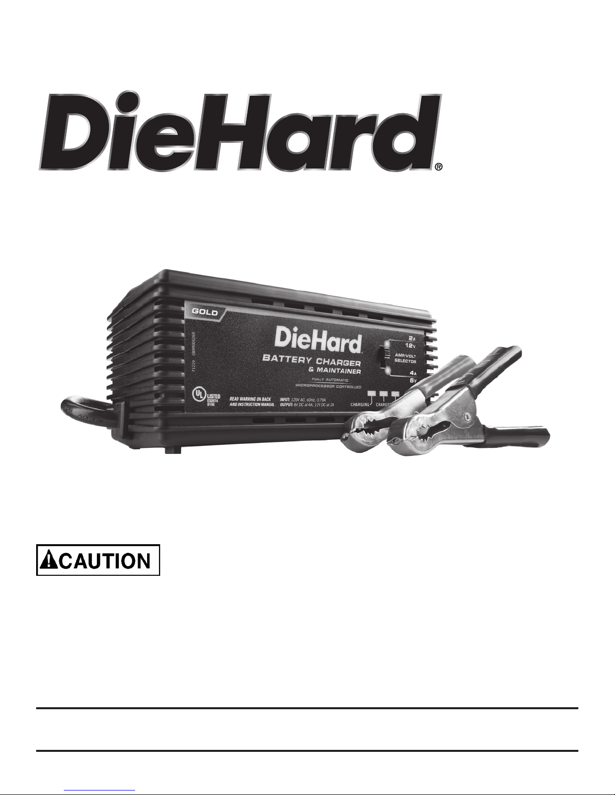
Battery Charger
Model No.
28.71219
Read and follow all Safety
Rules and Operating Instructions
before Every Use of this Product.
SAVE THESE INSTRUCTIONS.
Sears Brands Management Corporation,
Hoffman Estates, IL 60179 U.S.A.
00-99-000999/01
Page 2

Page 3

TABLE OF CONTENTS
SECTION PAGE
IMPORTANT SAFETY INSTRUCTIONS 2
PERSONAL PRECAUTIONS 3
PREPARING TO CHARGE 4
CHARGER LOCATION 5
DC CONNECTION PRECAUTIONS 6
FOLLOW THESE STEPS WHEN BATTERY IS INSTALLED
IN VEHICLE 6
FOLLOW THESE STEPS WHEN BATTERY IS
OUTSIDE VEHICLE 8
GROUNDING AND AC POWER CORD CONNECTIONS 9
ASSEMBLY INSTRUCTIONS 9
FEATURES/CONTROL PANEL 10
OPERATING INSTRUCTIONS 11
BATTERY PERCENT AND CHARGE TIMES 14
MAINTENANCE INSTRUCTIONS 15
MOVING AND STORAGE INSTRUCTIONS 16
TROUBLESHOOTING 16
BEFORE RETURNING FOR REPAIRS 17
DIEHARD THREE-YEAR FULL WARRANTY
When operated and maintained according to all supplied instructions, if this
DieHard product fails due to a defect in material or workmanship within 3
years from the date of purchase, return it to any DieHard outlet in the United
States for free replacement.
This warranty gives you specic legal rights, and you may also have other
rights which vary from state to state.
Sears Brands Management Corporation, Hoffman Estates, IL 60179
FOR CUSTOMER ASSISTANCE OR REPLACEMENT PARTS,
CALL TOLL-FREE FROM 7 AM TO 5 PM CT
MONDAY THROUGH FRIDAY: 1-800-732-7764
Page 4
IMPORTANT: READ AND SAVE THIS SAFETY AND INSTRUCTION
MANUAL.
SAVE THESE INSTRUCTIONS – The 71219 offers a wide range of
features to accommodate your needs. This manual will show you how
to use your charger safely and effectively. Please read, understand
and follow these instructions and precautions carefully, as this manual
contains important safety and operating instructions. The safety
messages used throughout this manual contain a signal word, a
message and an icon.
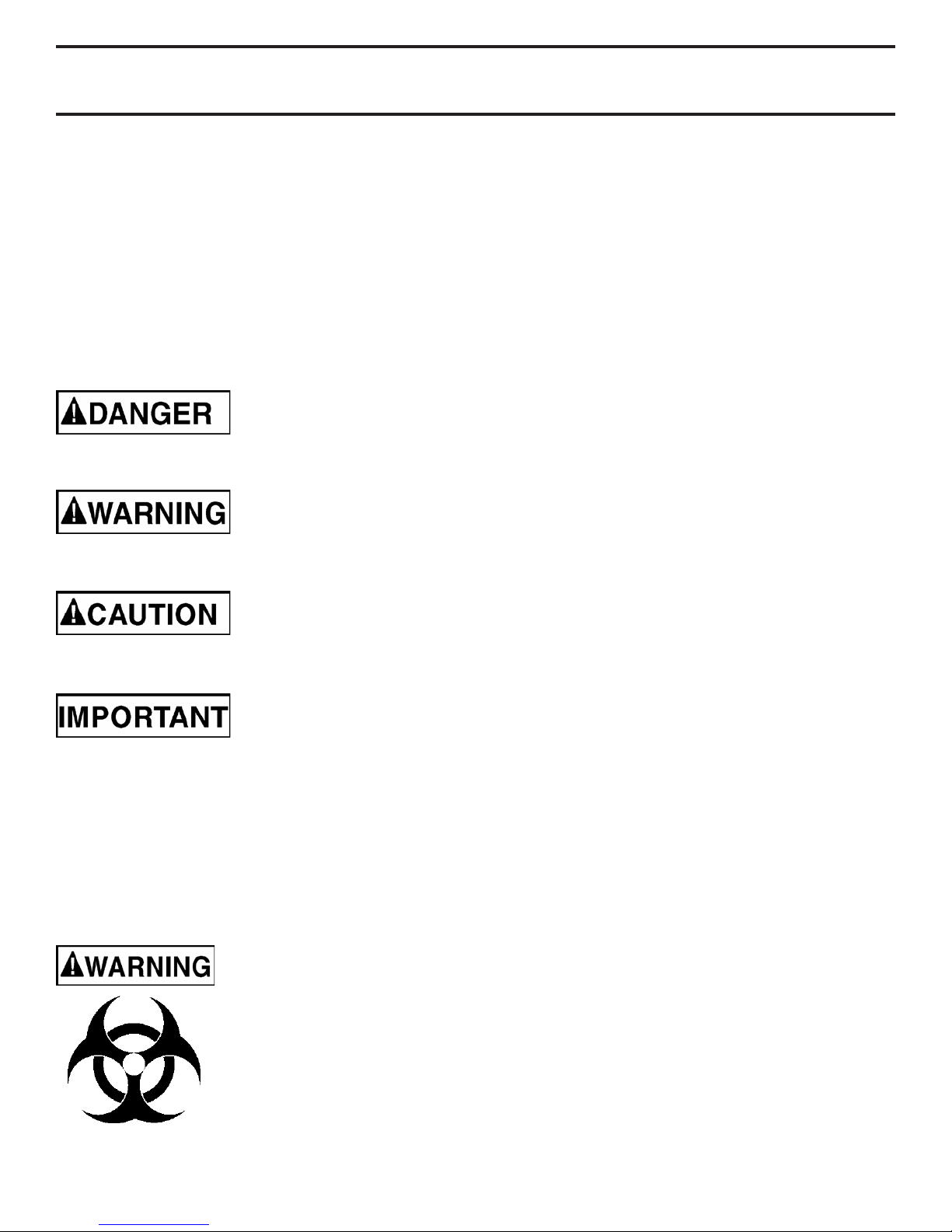
The signal word indicates the level of the hazard in a situation.
Indicates an imminently hazardous situation which, if
not avoided, will result in death or serious injury to the
operator or bystanders.
Indicates a potentially hazardous situation which, if not
avoided, could result in death or serious injury to the
operator or bystanders.
Indicates a potentially hazardous situation which, if not
avoided, could result in moderate or minor injury to the
operator or bystanders.
Indicates a potentially hazardous situation which, if not
avoided, could result in damage to the equipment or
vehicle or property damage.
Safety messages in this manual contain two different type styles.
Unnumbered type states the hazard.•
Numbered type states how to avoid the hazard.•
The icon gives a graphical description of the potential hazard.
Pursuant to California Proposition 65, this product
contains chemicals known to the State of California to
cause cancer and birth defects or other reproductive
harm.
1
Page 5

IMPORTANT SAFETY INSTRUCTIONS - SAVE THESE 1.
INSTRUCTIONS - This manual contains important safety and
operating instructions
RISK OF ELECTRIC SHOCK OR FIRE.
Keep out of reach of children.1.1
Do not expose the charger to rain or snow.1.2
Use only recommended attachments. Use of an attachment 1.3
not recommended or sold by the battery charger manufacturer
may result in a risk of re, electric shock or injury to persons or
damage to property.
To reduce the risk of damage to the electric plug or cord, pull by 1.4
the plug rather than the cord when disconnecting the charger.
An extension cord should not be used unless absolutely 1.5
necessary. Use of an improper extension cord could result in a
risk of re and electric shock. If an extension cord must be used,
make sure:
That the pins on the plug of the extension cord are the same •
number, size and shape as those of the plug on the charger.
That the extension cord is properly wired and in good •
electrical condition.
That the wire size is large enough for the AC ampere rating of •
the charger as specied in section 8.
To reduce the risk of electric shock, unplug the charger from the 1.6
outlet before attempting any maintenance or cleaning. Simply
turning off the controls will not reduce this risk.
Do not operate the charger with a damaged cord or plug; have 1.7
the cord or plug replaced immediately by a qualied service
person. (Call customer service at: 1-800-732-7764.)
Do not operate the charger if it has received a sharp blow, been 1.8
dropped or otherwise damaged in any way; take it to a qualied
service person. (Call customer service at: 1-800-732-7764.)
2
Page 6

Do not disassemble the charger; take it to a qualied service 1.9
person when service or repair is required. Incorrect reassembly
may result in a risk of re or electric shock. (Call customer
service at: 1-800-732-7764.)
RISK OF EXPLOSIVE GASES.
WORKING IN THE VICINITY OF A LEAD-ACID BATTERY IS 1.10
DANGEROUS. BATTERIES GENERATE EXPLOSIVE GASES
DURING NORMAL BATTERY OPERATION. FOR THIS
REASON, IT IS OF UTMOST IMPORTANCE THAT YOU
FOLLOW THE INSTRUCTIONS EACH TIME YOU USE
THE CHARGER.
To reduce the risk of a battery explosion, follow these 1.11
instructions and those published by the battery manufacturer
and the manufacturer of any equipment you intend to use in the
vicinity of the battery. Review the cautionary markings on these
products and on the engine.
This charger employs parts, such as switches and circuit 1.12
breakers, that tend to produce arcs and sparks. If used in a
garage, locate this charger 18 inches or more above oor level.
PERSONAL PRECAUTIONS2.
RISK OF EXPLOSIVE GASES.
NEVER smoke or allow a spark or ame in the vicinity of a 2.1
battery or engine.
Remove personal metal items such as rings, bracelets, 2.2
necklaces and watches when working with a lead-acid battery.
A lead-acid battery can produce a short-circuit current high
enough to weld a ring or the like to metal, causing a
severe burn.
3
Page 7

Be extra cautious to reduce the risk of dropping a metal tool 2.3
onto the battery. It might spark or short-circuit the battery or
other electrical part that may cause an explosion.
Use this charger for charging LEAD-ACID batteries only. It is 2.4
not intended to supply power to a low voltage electrical system
other than in a starter-motor application. Do not use this battery
charger for charging dry-cell batteries that are commonly used
with home appliances. These batteries may burst and cause
injury to persons and damage to property.
NEVER charge a frozen battery.2.5
NEVER overcharge a battery.2.6
Consider having someone close enough by to come to your aid 2.7
when you work near a lead-acid battery.
Have plenty of fresh water and soap nearby in case battery acid 2.8
contacts your skin, clothing or eyes.
Wear complete eye and body protection, including safety 2.9
goggles and protective clothing. Avoid touching your eyes while
working near the battery.
If battery acid contacts your skin or clothing, immediately 2.10
wash the area with soap and water. If acid enters your eye,
immediately ood the eye with cold running water for at least 10
minutes and get medical attention right away.
If battery acid is accidentally swallowed, drink milk, the whites of 2.11
eggs or water. DO NOT induce vomiting. Seek medical
attention immediately.
PREPARING TO CHARGE3.
RISK OF CONTACT WITH BATTERY ACID.
BATTERY ACID IS A HIGHLY CORROSIVE
SULFURIC ACID.
If it is necessary to remove the battery from the vehicle to 3.1
charge it, always remove the grounded terminal rst. Make sure
all of the accessories in the vehicle are off to prevent arcing.
4
Page 8

Be sure the area around the battery is well ventilated while the 3.2
battery is being charged.
Clean the battery terminals before charging the battery. During 3.3
cleaning, keep airborne corrosion from coming into contact
with your eyes, nose and mouth. Use baking soda and water to
neutralize the battery acid and help eliminate airborne corrosion.
Do not touch your eyes, nose or mouth.
Add distilled water to each cell until the battery acid reaches the 3.4
level specied by the battery manufacturer. Do not overll. For
a battery without removable cell caps, such as valve regulated
lead acid batteries (VRLA), carefully follow the manufacturer’s
recharging instructions.
Read, understand and follow all instructions for the charger, 3.5
battery, vehicle and any equipment used near the battery
and charger. Study all of the battery manufacturer’s specic
precautions while charging and recommended rates
of charge.
Determine the voltage of the battery by referring to the vehicle 3.6
owner’s manual and make sure that the output voltage selector
switch is set to the correct voltage. If the charger has an
adjustable charge rate, charge the battery in the lowest rate rst.
Make sure that the charger cable clips make tight connections.3.7
CHARGER LOCATION4.
RISK OF EXPLOSION
AND CONTACT WITH
BATTERY ACID.
Locate the charger as far away from the battery as the DC 4.1
cables permit.
Never place the charger directly above the battery being 4.2
charged; gases from the battery will corrode and damage
the charger.
Do not set the battery on top of the charger.4.3
Never allow battery acid to drip onto the charger when reading 4.4
the electrolyte specic gravity or lling the battery.
5
Page 9

Do not operate the charger in a closed-in area or restrict the 4.5
ventilation in any way.
DC CONNECTION PRECAUTIONS5.
Connect and disconnect the DC output clips only after setting 5.1
all of the charger switches to the “off” position (if applicable) and
removing the AC plug from the electrical outlet. Never allow the
clips to touch each other.
Attach the clips to the battery and chassis, as indicated in 5.2
sections 6 and 7.
FOLLOW THESE STEPS WHEN BATTERY IS INSTALLED 6.
IN VEHICLE
A SPARK NEAR THE BATTERY
MAY CAUSE A BATTERY
EXPLOSION. TO REDUCE THE
RISK OF A SPARK NEAR THE
BATTERY:
NEGATIVE GROUNDED SYSTEM
Position the AC and DC cables to reduce the risk of damage 6.1
by the hood, door and moving or hot engine parts. NOTE: If it
is necessary to close the hood during the charging process,
ensure that the hood does not touch the metal part of the battery
clips or cut the insulation of the cables.
Stay clear of fan blades, belts, pulleys and other parts that can 6.2
cause injury.
6
Page 10

Check the polarity of the battery posts. The POSITIVE (POS, 6.3
P, +) battery post usually has a larger diameter then the
NEGATIVE (NEG, N, -) post.
Determine which post of the battery is grounded (connected) to 6.4
the chassis. If the negative post is grounded to the chassis (as
in most vehicles), see step 6.5. If the positive post is grounded
to the chassis, see step 6.6.
For a negative-grounded vehicle, connect the POSITIVE 6.5
(RED) clip from the battery charger to the POSITIVE (POS,
P, +) ungrounded post of the battery. Connect the NEGATIVE
(BLACK) clip to the vehicle chassis or engine block away from
the battery. Do not connect the clip to the carburetor, fuel lines
or sheet-metal body parts. Connect to a heavy gauge metal part
of the frame or engine block.
For a positive-grounded vehicle, connect the NEGATIVE 6.6
(BLACK) clip from the battery charger to the NEGATIVE (NEG,
N, -) ungrounded post of the battery. Connect the POSITIVE
(RED) clip to the vehicle chassis or engine block away from the
battery. Do not connect the clip to the carburetor, fuel lines or
sheet-metal body parts. Connect to a heavy gauge metal part of
the frame or engine block.
Connect charger AC supply cord to electrical outlet.6.7
When disconnecting the charger, turn all switches to off (if 6.8
applicable), disconnect the AC cord, remove the clip from the
vehicle chassis and then remove the clip from the
battery terminal.
See CALCULATING CHARGE TIME for length of 6.9
charge information.
7
Page 11

FOLLOW THESE STEPS WHEN BATTERY IS OUTSIDE 7.
VEHICLE
A SPARK NEAR THE BATTERY
MAY CAUSE A BATTERY
EXPLOSION. TO REDUCE THE
RISK OF A SPARK NEAR THE
BATTERY:
Check the polarity of the battery posts. The POSITIVE (POS, 7.1
P, +) battery post usually has a larger diameter than the
NEGATIVE (NEG, N, -) post.
Attach at least a 24-inch (61 cm) long 6-gauge (AWG) insulated 7.2
battery cable to the NEGATIVE (NEG, N, -) battery post.
Connect the POSITIVE (RED) charger clip to the POSITIVE 7.3
(POS, P, +) post of the battery.
Position yourself and the free end of the cable you previously 7.4
attached to the NEGATIVE (NEG, N, -) battery post as far away
from the battery as possible – then connect the NEGATIVE
(BLACK) charger clip to the free end of the cable.
Do not face the battery when making the nal connection.7.5
Connect charger AC supply cord to electrical outlet.7.6
When disconnecting the charger, always do so in the reverse 7.7
order of the connecting procedure and break the rst connection
while as far away from the battery as practical.
A marine (boat) battery must be removed and charged on shore. 7.8
To charge it onboard requires equipment specially designed for
marine use.
8
Page 12

GROUNDING AND AC POWER CORD CONNECTIONS8.
RISK OF ELECTRIC SHOCK OR FIRE.
This battery charger is for use on a nominal 8.1
120-volt circuit and has a grounded plug that
looks like the plug illustrated. The charger must
be grounded to reduce the risk of electric shock.
The plug must be plugged into an outlet that is
properly installed and grounded in accordance
with all local codes and ordinances. The plug
pins must t the receptacle (outlet). Do not use
with an ungrounded system.
8.2 Never alter the AC cord or plug provided – if it
does not t the outlet, have a proper grounded outlet installed by
a qualied electrician. An improper connection can result in a
risk of an electric shock or electrocution. NOTE: Pursuant to
Canadian Regulations, use of an adapter plug is not allowed in
Canada. Use of an adapter plug in the United States is not
recommended and should not be used.
Recommended minimum AWG size for extension cord:8.3
100 feet long or less - use an 18 gauge extension cord.•
Over 100 feet long - use a 16 gauge extension cord.•
ASSEMBLY INSTRUCTIONS9.
Remove all cord wraps and uncoil the cables prior to using the battery
charger.
9
Page 13

FEATURES/CONTROL PANEL 10.
1
3
2
4
4
7
3
5
2
1
4
6
Amp/Volt Selector Switch1.
Battery Status LEDs2.
AC Power cord 3.
Battery Clamp Cable Assembly4.
Ring Terminal Cable Assembly5.
12V Plug Cable Assembly6.
Charger Quick-Connect Cable7.
Amp/Volt Selector Switch10.1
2A, 12V
AMP/VOLT
SELECTOR
4A, 6V
LED Display10.2
CHECK BATTERY (red) LED lit: Indicates the battery is not properly
connected to the charger.
10
Page 14

CHECK BATTERY (red) LED blinking: Indicates the charger is in
abort mode.
CHARGING (yellow) LED lit: Indicates the charger is charging
the battery.
CHARGED (green) LED lit: Indicates the battery is fully charged and
the charger is in maintain mode.
NOTE: See the Operating Instructions section for a complete
description of the charger modes.
OPERATING INSTRUCTIONS11.
This battery charger must be properly assembled in
accordance with the assembly instructions before it is used.
The charger does not have an On/Off switch. Plug the 71219 into
a 120V AC electrical wall outlet only after battery connections have
been made and the Amp/Volt selector switch has been set.
NOTE: This charger is equipped with an auto-start feature. It will not
supply current to the battery clips until a battery is properly connected.
Meaning, the clips will not spark if touched together.
Charging
Ensure that all of the charger components are in place and in 1.
good working condition, for example, the plastic boots on the
battery clips.
Connect the battery following the connection instructions 2.
described in Using the Quick-Disconnect Cable
Connectors section.
Set the Amp/Volt Selector switch to the proper setting for the 3.
battery being charged.
Connect the AC power following the precautions listed in 4.
section 8.
If you’ve connected everything correctly, the CHARGING 5.
(yellow) LED should be lit indicating that the charger is
charging. If the CHARGING (yellow) LED does not light or if
the CHECK BATTERY (red) LED is lit, check the connections
or have the battery checked/replaced.
11
Page 15

USING THE QUICK-DISCONNECT CABLE CONNECTORS
Connect any of the three output cable assemblies to the charger in
seconds. Make sure to place the charger on a dry, non-
ammable surface.
NOTE: Never connect the clamp and ring terminal connectors
together for use in other applications, such as external battery or
other power source charging, or to extend the output cable length, as
reverse polarity and/or overcharge conditions will occur.
50 AMP BATTERY CLIPS
Connect the end of the charger output cable to the end of the 1.
50 Amp Battery clips cable.
Follow the steps in sections 6 and 7 to connect the output 2.
clips to the battery.
After a good electrical connection is made to the battery, plug 3.
the power cord into a 3-prong grounded 120V AC electrical
wall outlet. Make sure to place the charger on a dry, non-
ammable surface.
PERMANENT RING CONNECTORS
The ring connectors permanently attach to the battery providing easy
access to quickly charge your battery. This application is appropriate
for motorcycles, lawn tractors, ATVs and snowmobiles.
To permanently attach to a battery, loosen and remove each 1.
nut from the bolt at the battery terminal.
Connect the red POSITIVE connector ring to the POSITIVE 2.
battery terminal.
Connect the black NEGATIVE connector ring to the 3.
NEGATIVE battery terminal.
Replace and tighten the nuts to secure. 4.
Connect the cable to the end of the charger output cord. 5.
Take care to keep the wires and plug away from metal and
moving parts.
Plug the charger power cord into a 3-prong grounded 120V 6.
AC electrical wall outlet. Make sure to place the charger on a
dry, non-ammable surface.
12
Page 16

12V ACCESSORY PLUG
Charge or maintain your battery without lifting the hood.
Connect the end of the 12V Accessory Plug Cable Quick-1.
Connect to the charger.
Insert the 12V accessory plug into the 12V accessory outlet.2.
Route the power cord from the charger through the vehicle’s 3.
open window.
Plug the charger power cord into a 3-prong grounded 120V 4.
AC electrical wall outlet. Make sure to place the charger on a
dry, non-ammable surface.
If the vehicle’s ignition key has to be on in order for the 5.
accessory outlet to supply/receive power, turn the key on.
Battery Connection Indicator
If the charger does not detect a properly connected battery, the
CHECK BATTERY (red) LED will light continuously until such
a battery is detected. Charging will not begin while the CHECK
BATTERY (red) LED is on. When charging begins, the CHARGING
(yellow) LED will be lit.
Completion of Charge
Charge completion is indicated by the CHARGED (green) LED. When
lit, the charger has stopped charging and switched to the Maintain
Mode of operation.
Maintain Mode (Float-Mode Monitoring)
When the CHARGED (green) LED is lit, the charger has started
Maintain Mode. In this mode, the charger keeps the battery
fully charged.
NOTE: If the charger has to provide its maximum maintain current for
a continuous 12 hour period, it will go into Abort Mode (see Aborted
Charge section). This is usually caused by a drain on the battery or
the battery could be bad. Make sure there are no loads on the battery.
If there are, remove them. If there are none, have the battery checked
or replaced.
13
Page 17

Maintaining a Battery
The 71219 is a battery maintainer that maintains both 6 and 12 volt
batteries, keeping them at full charge. It can charge small batteries
and maintain both small and large batteries. If you are maintaining
a fully charged large battery, you will be properly utilizing the battery
charger. However, if you were to use this battery charger to charge a
large battery, such as a marine deep cycle battery, that was not fully
charged, you may lose some of the battery’s capacity. This would
cause the large battery to be unable to hold a charge and become
useless. Therefore, we do not recommend charging a large battery
with this unit.
NOTE: The maintain mode technology utilized in DieHard’s chargers
allows you to safely charge and maintain a healthy battery for
extended periods of time. However, problems with the battery,
electrical problems in the vehicle, improper connections or other
unanticipated conditions could cause excessive current draws. As
such, occasionally monitoring your battery and the charging process
is recommended.
Desulfation Mode
If the battery is left discharged for an extended period of time, it could
become sulfated and not accept a normal charge. If the charger
detects a sulfated battery, the charger will switch to a special mode of
operation designed for such batteries. If successful, normal charging
will resume after the battery is desulfated. Desulfation could take up
to 8 hours. If desulfation fails, charging will abort and the CHECK
BATTERY (red) LED will blink.
Aborted Charge
If charging can not be completed normally, charging will abort. When
charging aborts, the charger’s output is shut off and the CHECK
BATTERY (red) LED will blink. To reset after an aborted charge,
unplug the charger from the outlet, wait a few moments and plug it
back in.
BATTERY PERCENT AND CHARGE TIMES12.
This charger adjusts the charging current in order to charge the
battery completely, efciently and safely.
This battery charger has a rated output of 2 and 4 amperes.
14
Page 18

Charging Times12.1
Battery Condition
2 Amp, 12 Volt Battery 50% Discharged 100% Discharged
Ampere Hour Battery
Capacity
Approximate Average Charge Time in
Hours
10 3.2 6.2
12 4.0 7.5
20 6.4 12.4
Battery Condition
4 Amp, 6 Volt Battery 50% Discharged 100% Discharged
Ampere Hour Battery
Capacity
Approximate Average Charge Time in
Hours
10 1.6 3.2
12 2.0 4.0
20 3.2 6.4
MAINTENANCE INSTRUCTIONS13.
After use and before performing maintenance, unplug and 13.1
disconnect the battery charger (see sections 6, 7 and 8).
Use a dry cloth to wipe all battery corrosion and other dirt or oil 13.2
from the terminals, cords, and the charger case.
Ensure that all of the charger components are in place and 13.3
in good working condition, including the plastic boots on the
battery clips.
Servicing does not require opening the unit, as there are no 13.4
user-serviceable parts.
All other servicing should be performed by qualied 13.5
service personal.
15
Page 19

MOVING AND STORAGE INSTRUCTIONS14.
Store the charger unplugged, in an upright condition. The AC 14.1
cord will still conduct electricity until it is unplugged from
the outlet.
Store inside, in a dry, cool place.14.2
Do not store the clips on or around metal, clipped together or 14.3
clipped to cables.
If the charger is moved around the shop or transported to 14.4
another location, take care to avoid/prevent damage to the
cords, clips and charger. Failure to do so could result in personal
injury or property damage.
TROUBLESHOOTING15.
PROBLEM POSSIBLE CAUSE
Charger will not turn
on when properly
connected, and no
LEDs are lit.
CHECK BATTERY
(red) LED is lit.
AC outlet is dead.
Poor electrical
connection.
Reverse connections
at battery.
Battery voltage is too
low.
REASON/
SOLUTION
Check for an open
fuse or circuit breaker
supplying the AC
outlet.
Check the power cord
and extension cord for
a loose tting plug.
Unplug the charger
and correct the lead
connections.
This charger has
an automatic start
feature. If the battery
voltage is under 0.2
Volts, the charger will
not detect it and will
not start the charging
process. Have the
battery checked/
replaced.
16
Page 20

PROBLEM POSSIBLE CAUSE
REASON/
SOLUTION
CHECK BATTERY
(red) LED is lit.
(continued)
CHECK BATTERY
(red) LED is blinking.
Battery clips do not
spark when touched
together.
Battery is not
properly connected to
the charger.
Charger is in abort
mode.
The charger is
equipped with an
auto-start feature.
It will not supply
current to the battery
clips until a battery is
properly connected.
Meaning, the clips
will not spark if
touched together.
Make sure the
connections from the
battery connector
cable to the battery
and to the charger are
tight.
See “Aborted Charge”
in the OPERATING
INSTRUCTIONS
Section.
No problem, this is a
normal condition.
BEFORE RETURNING FOR REPAIRS16.
When a charging problem arises, make certain that the battery 16.1
is capable of accepting a normal charge. Double check all
connections, the AC outlet for a full 120 volts, the charger clips
for correct polarity and the quality of the connections from the
cables to the clips and from the clips to the battery system. The
clips must be clean.
When an UNKNOWN OPERATING PROBLEM arises, please 16.2
read the complete manual and call the customer service number
for information that will usually eliminate the need for return.
If the above solutions do not eliminate the problem or
for information about troubleshooting or replacement parts, call toll-free
from anywhere in the U.S.A.
1-800-732-7764
7:00 am to 5:00 pm Central Time Monday through Friday
17
 Loading...