


PRELIMINARY - DRAFT COPY
Fri Feb 20 15:41:32 2009
Electronic Vault Attendant (EVA)
and EVA Elite
TP-821321-001A PD 6521
Product Description
and Operating Guide

PRELIMINARY - DRAFT COPY
Fri Feb 20 15:41:32 2009

PRELIMINARY - DRAFT COPY
Fri Feb 20 15:41:32 2009
Electronic Va
and EVA Elite Product Description
March 2009
TP-821321-001A PD 6521
ult Attendant (EVA)
and Operating Guide

PRELIMINARY - DRAFT COPY
Fri Feb 20 15:41:32 2009
Document History
Document Number Date Remarks
TP-821321-001A
3/2009 Original edition
Copyright protection is claimed for each revision listed in the document history, as of the date indicated.
Any trademarks, service marks, product names or company nam es not owned by Diebold, Incorporated or its
subsidiaries (collectively "Diebold") that appear in this document are used for informational purposes on ly and
Diebold claims no rig hts thereto , nor does such use indicate any affiliation with or any endorsement of Diebold or
Diebold products by the owners thereof.
This document contains proprietary information. If the document pages state the information is confidential
(or words of similar imp ort), then this document is intended solely for the use of the copyright owner's
employees or other personnel expressly authorized in writing by the copyright owner. Other uses of this
information without the express written consent of the copyright owner are prohibited. This document should
be treated as confidential material for security reasons. Any unauthorized disclosure or use of confidential
material may violate Section 1832 of Title 18 of the United States Code as well as other la ws, and may be
punishable by fine and imprisonment.
The information contained in this document is subject to change without notice. When using the document for system
implementation, please call your authorized sales or service representative for any applicable changes.
This document and the information contained herein are provided AS IS AND WITHOUT WARRANTY. In
no event shall the copyright owner o r its suppliers be liable for any special, indirect, or consequential damages
of any nature resulting from the use of information in this manual.
No part of this document may be reproduced, stored in a retrieval system, or transmitted , in any f orm or by any
means: electronic, mechanical, photocopying, recording, or otherwise, without prior written permission from the
copyright owner.
Your use of this document and/or any of the information contained herein constitutes your agreement to all of the
terms stated on this page.
Diebold continually strives to improve its products. If you would like to comment on the accuracy, clarity,
organization or value of this document, please contact us at documentationservices@diebold.com or address
correspondence to:
Diebold, Incorporated
Att: Documentation Services 9-B-16
5995 Mayfair Road
North Canton, OH 44720
ii
Copyright ©Diebold, Incorporated (3/2009) - All Rights Reserved
TP-821321-001A

PRELIMINARY - DRAFT COPY
Fri Feb 20 15:41:32 2009
Contents
Section1 Introduction ............................................ 1-1
1.1 PartsandService ........................................ 1-1
1.2 Safety Precautions ....................................... 1-1
1.3 ReferenceDocumentation ................................... 1-1
1.4 CustomerResponsibilities ................................... 1-2
1.5 GeneralDescription ....................................... 1-2
1.5.1 GeneralDescriptionandPurpose ........................... 1-2
1.5.2 Components ...................................... 1-3
1.5.2.1 EVA ..................................... 1-3
1.5.2.2 EVAElite .................................. 1-4
1.5.3 Operation ........................................ 1-7
1.5.3.1 EVA (vault access control only) ...................... 1-7
1.5.3.2 EVA Elite (vault and SD box access control) ............... 1-8
Section 2 Configurations ........................................... 2-1
2.1 Options ............................................. 2-1
2.1.1 SecurityOptions .................................... 2-1
2.1.2 UPS ........................................... 2-1
2.2 System Configuration ...................................... 2-1
Section3 GeneralGuidelines ......................................... 3-1
3.1 ApplyingandRemovingPower................................. 3-1
3.1.1 ApplyingPowertotheEVATouchScreenWorkstation ................ 3-1
3.1.2 RemovingPowerfromtheEVATouchScreenWorkstation.............. 3-2
3.2 CleaningGuidelines....................................... 3-2
Figures
Figure 1-1 EVA Vault Access Components ................................. 1-4
Figure1-2 EVAEliteComponents ..................................... 1-5
Figure1-3 BasicEVAEliteSystemComponents .............................. 1-6
Figure1-4 OptionalSecurityComponents ................................. 1-6
Figure1-5 DockingAssemblyandKeyAssembly ............................. 1-9
Figure1-6 KeyAssembly .......................................... 1-10
Figure1-7 SDBoxWithLockAssembly .................................. 1-10
Figure1-8 LockHousinginOpenPosition ................................. 1-11
Copyright ©Diebold, Incorporated (3/2009) - All Rights Reserved
TP-821321-001A
iii

PRELIMINARY - DRAFT COPY
Fri Feb 20 15:41:32 2009
PREFACE TO FCC NOTICE
Diebold requires each of its products to undergo complete testing before shipment. Each product must pass stringent
requirements of quality control. In addition, much effort and consideration has been devoted to assure the utmost
in reliable equipment operation.
FCC NOTICE
This device complies with part 15 of the FCC Rules. Operation is subject to the following two conditions: (1) This
device may not cause harmful interference, and (2) this device must accept any interference received, including
interference that may cause undesired operation.
CAUTION
Changes or mo
difications of this product not expressly approved by Diebold could void the
user's authority to operate the equipment.
iv
Copyright ©Diebold, Incorporated (3/2009) - All Rights Reserved
TP-821321-001A

Section 1
Introduction
1.1 Parts and Service
1.2 Safety Precautions
PRELIMINARY - DRAFT COPY
Fri Feb 20 15:41:32 2009
Parts and service for the pro duct described herein are available from your
Diebold representative. You may also call Diebold toll free at 1-800-DIEBOLD.
Additional information about products, support, and replacement items is
available on Diebold's Web site at www.diebold.com.
Diebold recommends strict observance of safety precautions. Observing safety
precautions reduces the risk of equipment damage and personal injury.
WARNING
1.3 Referenc
e Documentation
Refer to t he following manuals for additional informatio n:
• 223-Series Daygate Installation Guide (TP-821074-001B)
• Electro
(TP-821366-001A)
You must observe the following precautions when operating
the product
severe personal injury, or death.
• Never insert screwdrivers, pens, or other instruments
into the con
bodily injury, death from electrical shock, or equipment
damage can result.
•Repairor
by qualified personnel.
• Changes or modifications of this product not expressly
approved b
operate the equipment.
nic Vault Attendant (EVA) Hardware Installation Guide
described herein to avoid equipment damage,
trol panel or other electrical devices. Severe
service procedures must always be performed
y Diebold could void the user's authority to
• Electronic Vault Attendant (EVA) Elite Hardware Installation
Guide(TP
Copyright ©Diebold, Incorporated (3/2009) - All Rights Reserved
TP-821321-001A
-821320-001A)
1-1

PRELIMINARY - DRAFT COPY
• EVA and EVA Elite Electronic Vault Attendant Setup and Administration
Guide (TP-821366-001B)
• EVA Quick Enrollment Guide (TP-821374-001A)
1.4 Customer Responsibilities
Network
If the customer has remote access to EVA, the customer is responsible for the
following items:
• Data communications lines
• Personal co mp uters (PCs) on t he network
• Network communications
• Network security
Operating Environment
The c ustom e r must provide a suitable operating environment for the equipm e nt.
An environment suitable for a PC, with appropriate thermal control and filtered
air, is recommended. The customer is responsible for cleaning the EVA
components.
Fri Feb 20 15:41:32 2009
Maintenance
The customer is responsible for the following maintenance:
• Backing up databases
• Backing up the system
• Maintaining hardware and software documentation
• Maintaining software CDs supplied with the system
Peripherals
The following peripherals may be required to perform maintenance of the EVA
software, and are the responsibility of the customer:
•USBCDdrive
• Compact flash
•USBflash drive
1.5 General Description
1.5.1 General Description and Purpose
The E lectronic Vault Access (EVA) system manages and provides secure access
to a vault without guidance or directi on by institution personnel. The system
functions as a screening device that identifies and automatically allows or denies
access to a vault area that is secured using a daygate. Additionally, a computer
record of each entry is recorded by the system.
1-2
Copyright ©Diebold, Incorporated (3/2009) - All Rights Reserved
TP-821321-001A

1.5.2 Components
1.5.2.1 EVA
PRELIMINARY - DRAFT COPY
Fri Feb 20 15:41:32 2009
The EVA Elite system manages and provides secure access to safe deposit
(SD) boxes without guidance or direction by institution personnel. The system
functions as a screening device that identifies and automatically allows or denies
access to the vault and to a specific safe deposit box. Additionally, a computer
record of each entry is recorded by the system.
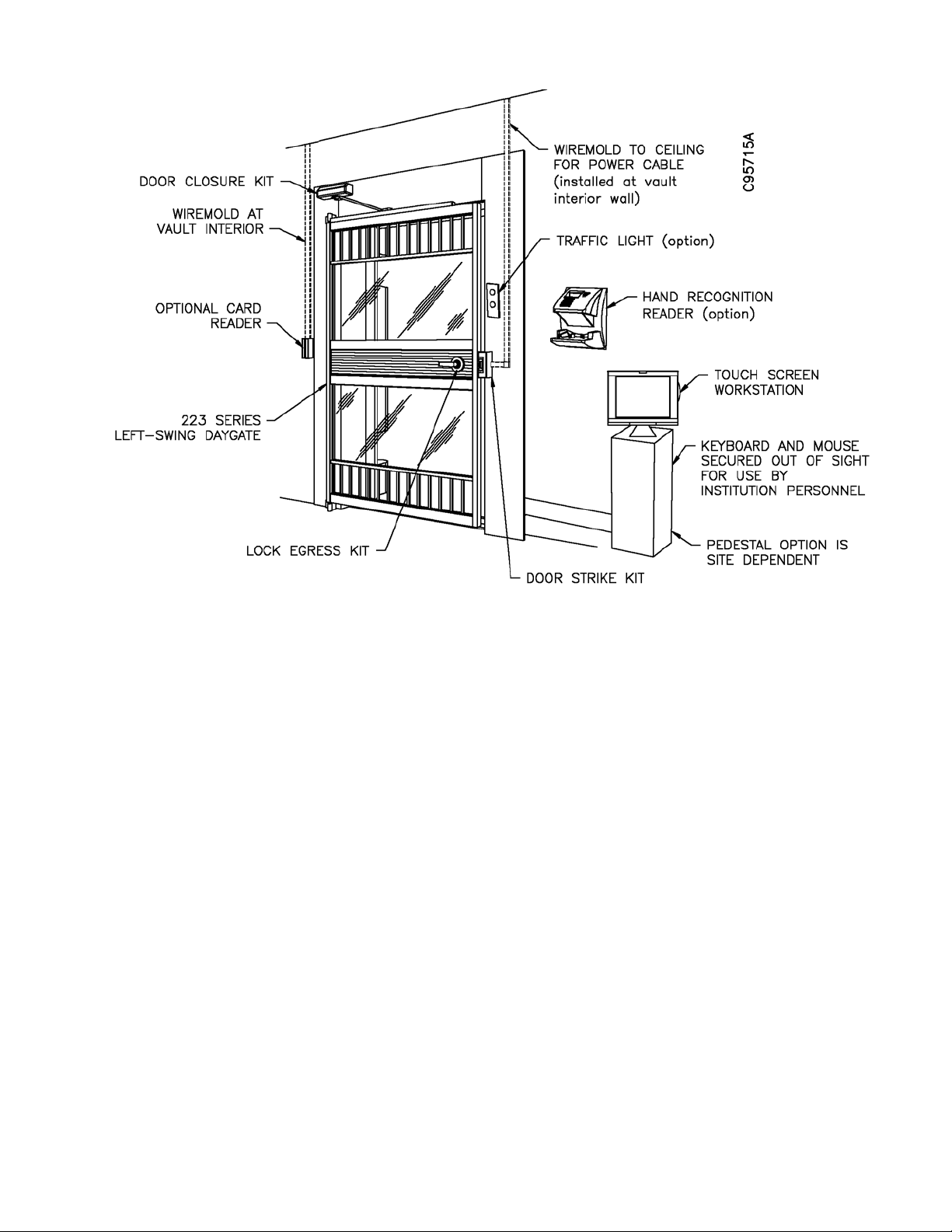
This system is configured to provide access control to the vault area and
modification to the daygate is required (Figure 1-1). The following items may be
installed as access control devices at the vault area:
• Touch screen workstation, with keyboard and mouse (standard)
• Door closure kit
• Lockset egress kit or Egress button kit (not bo th)
• Additional access control for vault access may include the following:
- Biometric hand recognition reader
-Traffic light for one-at-a-time vault access
- Card swipe reader
- Signature capture device
- Biometric pad (fingerprint reader)
- Video surveillance
Copyright ©Diebold, Incorporated (3/2009) - All Rights Reserved
TP-821321-001A
1-3
PRELIMINARY - DRAFT COPY
Fri Feb 20 15:41:32 2009
1.5.2.2 EVA Elite
NOTE
With bar daygate, an egress button may be installed at the vault interior.
Figure 1-1 E VA Vault Access Components
Basic Components
In addition to the basic components required for the basic EVA system, the
following items are components of the EVA Elite system (Figure 1-2):
• Touch screen workstation, with keyboard and mouse (Figure 1-3)
• Docking assembly
• Key assembly
• Lock assembly
The institution may request one or all of the following security com ponents be
installed for access control (Figure 1-4):
• Biometric hand recognition reader
• Signature capture device
• Bio metric pad (for example, fingerprint or thumbprint reader)
1-4
Copyright ©Diebold, Incorporated (3/2009) - All Rights Reserved
TP-821321-001A

PRELIMINARY - DRAFT COPY
Fri Feb 20 15:41:32 2009
Figure 1-2 EVA Elite Com p onents
Copyright ©Diebold, Incorporated (3/2009) - All Rights Reserved
TP-821321-001A
1-5

PRELIMINARY - DRAFT COPY
Fri Feb 20 15:41:32 2009
1 Touch screen workstation 3 Docking assembly 3 Key asse mbly
4 Hand recognition reader
5
Lock assembly
----
Figure 1-3 Basic EVA Elite System Components
NOTE
Items shown are for reference only. Actual components may differ in appearance.
1
Signature pad
2Biometricpad
Figure 1-4 Optional Security Components
1-6
Copyright ©Diebold, Incorporated (3/2009) - All Rights Reserved
TP-821321-001A

PRELIMINARY - DRAFT COPY
Fri Feb 20 15:41:32 2009
1.5.3 Operation
Before a customer can perform the procedures in this section, the customer must
be enrolled in the EVA database and the biometric hand recognition reader. These
procedures are provided in EVA and EVA Elite Electronic Vault Attendant Setup
and Administration Guide (TP-821366-001B).
The procedures described in this section provide a general overview of how the
EVA and EVA Elite systems function. Operation at a specific site is dependent on
the specific components of the system and the configuration of the software.
1.5.3.1 EVA (vault access control only)
1. An individual requiring access to the vault enters required data using
a touch screen workstation (item 1, Figure 1-3). This data may be
configured to include some, or all, of the following:
• Personal i dentification number (PIN)
• Swipe card reader on touch screen workstation
•Pre-defined personal information
To provide additional security measures, the institution may require that
the individual also use one or more of the following optional components:
• Biometric hand recognition reader
• Sig nature capture device
• Biometric pad (for examp le, fingerprint or thumbprint reader)
• Card sw ipe reader at vault entrance
2. When the system validates the information provided in Step 1, the system
unlocks the daygate latch bolt to allow access to the vault area.
3. The individual proceeds to the assigned SD box. Generally, the keyway
formerly used by institution personnel (guard nose) is concealed by a
protective cap to prevent access to the keyway. Only the customer key
is available.
4. The individual inserts the customer key into the keyway of the customer
keylock and rotates the key to open the SD lock, providing access to
the SD box.
The system may be configured to prohibit m ore than one customer into the v ault
at a time. In this instance, an optional traffic light installed on the vault exterior
will indicate when the vault is available (green lamp) and when it is occupied
(red lamp).
Copyright ©Diebold, Incorporated (3/2009) - All Rights Reserved
TP-821321-001A
1-7

PRELIMINARY - DRAFT COPY
Fri Feb 20 15:41:32 2009
1.5.3.2 EVA Elite (vault and SD box access control)
1. An individual requiring access to an SD box enters required data using a
touch screen workstation. This data may be configuredtoincludesome,
or all, of the following:
• Personal i dentification number (PIN)
• Swipe card reader on touch screen workstation
•Pre-defined personal information
To provide additional security measures, the institution may require that
the individual also use one or more of the following optional components:
• Biometric hand recognition reader
• Sig nature capture device
• Biometric pad (for examp le, fingerprint or thumbprint reader)
• Card sw ipe reader at vault entrance
2. When the system validates the information provided in Step 1, a
light-emitting diode (LED) on the docking assembly illuminates to
designate t he programmed key assembly. The docking station holds up to
three key assemblies. See Figu re 1-5.
3. The individual removes the programmed key assembly from the docking
assembly. The small LCD screen (Figure 1-6) on the key assembly
displays the SD box number assigned to the data entered in Step 1.
4. With the key assembly in hand, the individual proceeds to the vault area.
The following access control device may be mounted near the closed
daygate to control access to the vault area:
• Hand recognition reader
• Card swipe reader
• Bio metric pad
Using the designated access control system, the individual performs the
required procedure using a device mounted near the vault opening. See
Figure 1-1.
5. The access control system unlocks the daygate latch bolt to allow access
to the vault area.
6. The individual proceeds to the assigned SD box and inserts the
programmed key assembly into the assigned lock assembly on the
numbered SD box door. The key assembly may only be inserted one way,
with the flat bottom facing the SD box. See Figure 1-7.
7. When the programmed key assembly is inserted into the assigned lock
assembly, the lock housing cover on the lock assembly swing s open t o
provide access to the customer keylock of the SD box door. The key
assembly remains in the lock assembly. See Figure 1-8.
1-8
If the programmed key assembly is inserted into the wrong lock assembly,
the lock housing cover will not open. A ccess to the unassigned custom er
keylock is denied.
Copyright ©Diebold, Incorporated (3/2009) - All Rights Reserved
TP-821321-001A

PRELIMINARY - DRAFT COPY
Fri Feb 20 15:41:32 2009
8. The individual inserts the customer key into the keyway of the customer
keylock and rotates the key to open the SD lock, providing access to
the SD box.
9. After the customer removes the SD box and accesses the SD box, the
customer performs the following steps to complete the transaction.
a. Returns SD box to the opening.
b. Closes the SD box door.
c. Uses customer key to lock customer keylock. Removes customer key.
d. Closes lock assembly cover. Removes key assembly.
e. Exits vault area.
f. Returns key assembly to docking assembly.
The system may be configured to prohibit m ore than one customer into the v ault
at a time. In this instance, an optional traffic light installed on the vault exterior
will indicate when the vault is available (green lamp) and when it is occupied
(red lamp).
Figure 1-5 Docking Assembly and Key Assembly
Copyright ©Diebold, Incorporated (3/2009) - All Rights Reserved
TP-821321-001A
1-9

PRELIMINARY - DRAFT COPY
Fri Feb 20 15:41:32 2009
Figure 1-6 Key Assembly
1-10
Figure 1-7 SD Box With Lock Assembly
Copyright ©Diebold, Incorporated (3/2009) - All Rights Reserved
TP-821321-001A

PRELIMINARY - DRAFT COPY
Fri Feb 20 15:41:32 2009
Figure 1-8 Lock Housing in Open Position
Copyright ©Diebold, Incorporated (3/2009) - All Rights Reserved
TP-821321-001A
1-11

PRELIMINARY - DRAFT COPY
Fri Feb 20 15:41:32 2009
1-12
Copyright ©Diebold, Incorporated (3/2009) - All Rights Reserved
TP-821321-001A

Section 2
Configurations
2.1 Options
2.1.1 Security Options
PRELIMINARY - DRAFT COPY
Fri Feb 20 15:41:32 2009
Using safe deposit access system software and basic USB cable connections, the
basic EVA Elite system may be configured to add components that may be used
to verify the identity of SD box customers.
Examples of these components are as follows:
• Card swipe reader
• Signature pad
• Bio metric pad (fingerprint recognition)
2.1.2 UPS
The uninterruptible power supply or UPS p revents data corruption by performing
an orderly shutdown of the EVA application and operating system in the event of
a power outage.
2.2 System Configuration
Use system configuration functions to change default settings an d to set up
and customize the EVA Elite system. Administrative control and software
configuration may be performed using the following m etho ds:
• Keypad and mo use at the touch screen workstation
• Optional PC workstation on a network hub
Copyright ©Diebold, Incorporated (3/2009) - All Rights Reserved
TP-821321-001A
2-1

PRELIMINARY - DRAFT COPY
Fri Feb 20 15:41:32 2009
2-2
Copyright ©Diebold, Incorporated (3/2009) - All Rights Reserved
TP-821321-001A

PRELIMINARY - DRAFT COPY
Fri Feb 20 15:41:32 2009
Section 3
General Guidelines
3.1 Applying and Removing Power
This section provides information on the following topics:
• Applying power to the EVA touch screen workstation (Section 3.1.1)
• Removing power from the EVA touch screen workstation (Section 3.1.2)
3.1.1 Applying Power to the EVA Touch Screen Workstation
Procedure
Perform the following procedure to apply power to the EVA touch screen
workstation and start the EVA application.
1. Verify the 12 VDC power supply for the EVA touch screen workstation is
installed, as described in the EVA Electronic Vault Attendant Hardware
Installation Guide (TP-821365-001A).
2. Press the power button on the right side of the EVA touch screen
workstation.
3. The EVA touch screen workstation boots up to the initial customer page
of the EVA application.
NOTE
No logon is required to access the initial customer p age
of the EVA application.
Copyright ©Diebold, Incorporated (3/2009) - All Rights Reserved
TP-821321-001A
3-1

PRELIMINARY - DRAFT COPY
Fri Feb 20 15:41:32 2009
3.1.2 Removing Power from the EVA Touch Screen Workstation
Procedure When Logged On as an Administrator
Perform the following procedure to remove power from the EVA touch screen
workstation.
1. If necessary, access the Administrator desktop as described in the
procedure in EVA and EVA Elite Electronic Vault Attendant Setup an d
Administration Guide (TP-821366-001B).
2. If you are logged in to the EVA application, log ou t. If necessary, refer to
EVA and EVA Elite Electronic Vault Attendant Setup and Ad min istration
Guide (TP-821366-001B) for the procedure to log out.
3. From the Windows taskbar, use the following path:
Start > Shut Down
4. On the Shut Down Windows window, select Shut Down and then select
OK.
3.2 Cleaning Guidelines
5. Wait while the Windows operat ing system s hut s down .
6. Disconnect the 12 VDC power supply for the EVA touch screen
workstation.
Procedure When Logged On as an Operator
Perform the following procedure to remove power from the EVA touch screen
workstation.
1. Press and hold the power button on the right side of the EVA touch
screen workstation for 7 seconds.
2. Wait while the Windows operat ing system s hut s down .
3. Disconnect the 12 VDC power supply for the EVA touch screen
workstation.
Guidelines
Observe the following guidelines for cleaning the EVA touch screen workstation:
3-2
WARNING
To avoid ri
from the EVA touch screen workstat ion before cleaning.
sk of electric shock, remove power (Section 3.1.2)
Copyright ©Diebold, Incorporated (3/2009) - All Rights Reserved
TP-821321-001A

PRELIMINARY - DRAFT COPY
Fri Feb 20 15:41:32 2009
CAUTION
Avoid getting liquids inside your EVA touch screen
workstation. If liquid does get inside, have a qualified
service techn
before you power it on again.
• Do not use alcohol (methyl, ethyl or isopropyl) or any strong dissolvent. Do
not use thinne
• To clean the EVA touch screen workstation housing, use a cloth lightly
dampened with a mild detergent.
ician check the EVA touch screen workstation
r or benzene, abrasive cleaners or compressed air.
• Do not wipe t
he screen with a cloth or sponge that could scratch the surface.
• To clean the touchscreen, use window or glass cleaner. Put the cleaner on
a rag and wipe the touchscreen. Never apply the cleaner directly on the
touchscreen
.
Copyright ©Diebold, Incorporated (3/2009) - All Rights Reserved
TP-821321-001A
3-3
 Loading...