

Page 1
DICKSON
KT6
Temperature Chart Recorder
Contents:
Product Specications
Operating Instructions, Alarm Relays & Display Symbols
Charts & Accessories
Instrument Anatomy
Getting Started / Installation
Keypad Operation
Dip Switch Setup & Calibration
Troubleshooting, Warranty / Factory Service & Returns
Order Form
DICKSON
Specications
Product
Display Symbols
Information &
Operating
Accessories
Charts &
Instrument
Anatomy
Rev. 03/04
Installation
Started/
Getting
Operation
Keypad
Dip Switch
Calibraion
Setup &
Troubleshooting
Warranty &
Returns
Page 2
Rev. 03/04
Product Specications
DICKSON
Specications
Product
KT603
Temperature Ranges 0 to -100°F/C, 0 to -50°F /C, -50 to 50°F/C, 0 to 50°F/C,
(user selectable): 50 to 100°F/C, 0 to 100°F/C, 0 to 250°F/C
Recorder Accuracy: ±.5% of chart range and ±1.8°F (1°C) Recorder only
Sensor Compatibility:
available on special order)
Ambient Operating Conditions: +32 to +122˚F (0 to +50˚C) 0 to 95% RH (non-condensing)
Recording Time (user selectable): 24 hour and 7 day
Power: 120V 50/60Hz (240V 50/60Hz models available)
Power Cord: 6’ (2m), cord with wall transformer
Power Status: LED indicator
Battery Back-up: One 9V alkaline battery
Battery Back-up Life: Up to 24 hours
4’ Teon coated K-Thermocouple beadwire probe with
Probe:
mini- connector
Calibration : User: Adjustable zero point; Factory: zero and span
Chart Size: 6” (152mm) diameter
Alarm Contacts:
alarm contacts)
Digital Display: LCD 3.5 digit
Keypad Functions:
calibration
Digital Display Resolution:
below -9.9˚
Response Time: 30 seconds at 63% of full scale
Mounting: Surface or panel mount, DIN compatible
Enclosure Dimensions: 7.56” x 7.56” x 3.25” (192mm x 192mm x 83mm)
Panel Cut-out Dimensions: 6.9” x 6.9” (188mm x 188mm)
Depth Behind Panel: 2.0” (51mm)
Included With Recorder:
4’ Bead Wire Probe
Standard K-Thermocouple (other temperature sensor types
User selectable MAX/MIN set points (set in conjunction with
ON/OFF, pen home, time adjust, alarm set (available) and
0.1˚ resolution -9.9˚ to 199.9˚; 1˚ resolution above 200˚ and
AC Adapter, Pen 9V Battery, Starter Pack of (C657) Charts and
KT655
Display Symbols
Information &
Operating
Accessories
Charts &
Instrument
Anatomy
Installation
Started/
Getting
Operation
Keypad
Rev. 03/04
Calibration
Dip Switch
Setup &
Troubleshooting
Warranty &
Returns
Page 3
Operating Information
Pen:
Hysteresis ( a property that occurs when tension is
applied to an object) causes the pens to move in
increments across the chart as the sensor readings
change. However, the display readings are not
affected by the property of hysteresis. For this
reason the display provides smoother and faster
readings than the pen. At any given time there may
be a slight discrepancy in the positions of the pens
and the readings on the display.
For visual spot checks the display is the
most accurate but both are within the stated
specications of the unit (see “Specications”).
Pens (2 pen KT6):
The blue pen has a longer pen arm than the red
pen. The pens are offset to allow the red pen to
glide under the blue pen. The blue pen indicates the
correct time and the red pen precedes it by 3/16 of
an inch.
Power Supply:
We recommend using AC Power with one 9V battery
installed as a back-up power source. This ensures
that your recording will not be interrupted when
there is a power failure. The AC Adapter is built into
the back of the recorder. NOTE: When the unit is
in battery back- up mode, the recorder will update
temperature readings at a much slower rate. The
battery should be replaced once a year and after
power failures of more than a few hours.
To Replace Battery:
1. Open the door of the recorder by depressing the
door latch.
2. Press the “HOME” key
3. Lift the chart, if there is one present, to fully
expose the battery compartment and press down
on the tab to release battery compartment door.
4. Replace 9V battery
Alarm Relays
The SPST 24V 500mA relay contacts are normally open and will close on alarm conditions when the alarms
are enabled. Relay contacts are always functional when the alarm is enabled. Dip Switch #8 has no effect
on the relay. The relay will close only during minimum and maximum alarm conditions. 2 pen units have two
sets of relay contacts which operate independently.
NOTE: For compliance to CE directives, do not remove the rubber cover from the alarm relay terminals when
the terminals are not used.
DICKSON
Specications
Product
Display Symbols
Information &
Operating
Accessories
Charts &
Instrument
Anatomy
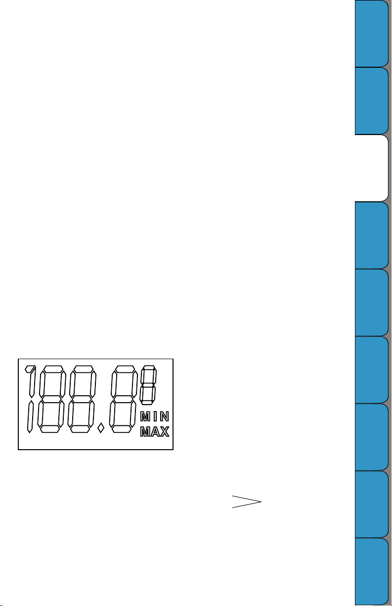
Display Symbols (optional)
Figure 4
Rev. 03/04
C: Indicates ˚C
F: Indicates ˚F
0: Zero calibration mode
A: Alarms enabled or alarm set mode
MIN:
This symbol is displayed when you are setting a
minimum alarm or during a minimum alarm condition
(when alarms are enabled)
MAX:
This symbol is displayed when you are setting a
maximum alarm or during a maximum alarm
condition (MIN and MAX ash when the alarms are
enabled and no alarm condition exists)
1: Channel One
2: Channel Two
Two channel units only
Installation
Started/
Getting
Operation
Keypad
Calibration
Dip Switch
Setup &
Troubleshooting
Warranty &
Returns
Page 4

Rev. 03/04
Charts & Accessories
(for current pricing go to www.dicksonweb.com or call 1-800 -323 -2448)
Range 24 Hour Char t 7 Day Chart
-50 to +50°F/C C652 C650
0 to ±50°F/C C654 C653
0 to ±100°F/C C658 C657
0 to +250°F/C C660 C659
0 to +500°F/C C662 C661
50 to +100°F/C C656 C655
DICKSON
Specications
Product
Description Order #
NIST Traceable Calibration 3 -pt. (new unit) N300
NIST Traceable Calibration 1-pt. (new unit) N100
A2LA Accredited Calibration 3-pt. (new unit) N400
Pens (single pen unit) (6 red) P222
Pens (dual pen unit) (3 red/3 blue) P266
Extended 2 year Warranty E200
Display Symbols
Information &
Operating
Accessories
Charts &
Instrument
Anatomy
Installation
Started/
Getting
Operation
Keypad
Dip Switch
Calibraion
Setup &
Troubleshooting
Warranty &
Returns
Page 5

Instrument Anatomy
O/I
Dip Switches
Figure 1
Pen Cap HoldersDoor Latch
Digital Display
(optional)
Dip Switch
Setting Chart
Compartment
DICKSON
Specications
Chart Guide
Clips
Chart Hub Time Arrow LEDKeypad9V Batter y
Pen Assembly
Product
Display Symbols
Information &
Operating
Accessories
Charts &
Instrument
Anatomy
Figure 2
Input Jack 0 -5V/
0-20mA
K-Thermocouple
Jack
Relay Contact
(optional)
Rev. 03/04
Panel Mount Holes
Key Hole/Wall
Mount Holes
K-Thermocouple Jack
(2 Thermocouple unit,
Pen #1, Blue)
Relay Contact (Pen #1,
Blue, 2 pen unit only)
AC/DC Adapter
Installation
Started/
Getting
Operation
Keypad
Dip Switch
Calibraion
Setup &
Troubleshooting
Warranty &
Returns
Page 6

Rev. 03/04
Getting Started
Your KT6 recorder has been preset to operate using
the most popular set tings. To change the range, use
dip switches (page 6). NOTE: Dip switches can only be
changes when unit is off.
Recording Time: 7 day
Range : 0 to 100˚F
A pen(s) and a chart have already been installed for
your convenience. All you need to do to start using your
KT6 recorder with the settings listed above is follow
these quick start instructions:
1. Plug in the AC adapter
2. Plug in thermocouple probe(s).
NOTE: Be sure to observe proper polarity when
connecting wires from transmitter.
3. Remove the protective pen cap from red pen
and insert on Pen Cap Holder.
4. Press the “ON/OFF” key to turn instrument ON.
(see “Keypad Operation”)
5. The instrument will enter a 5 second warm -up
phase, ending with the pen(s) moving to the
appropriate temperature reading(s). Under warm up mode the green LED ashes until ready. When
ready, LED will stay solid green.
6. Set the appropriate time by pressing the “CHART
ROTATION” key on the lower right of the dial
plate. The chart will turn clockwise while the
button is depressed. ( CAUTION : Do not
manually try to turn the chart hub. Doing
so may damage instrument). Continue the
rotation until the correct hour and day on
the chart is referenced to the timing arrow. (See
“Instrument Anatomy)
DICKSON
Specications
Product
Display Symbols
Information &
Operating
Installation
Before you install your KT6 recorder, read through this
entire manual to nd out about all the options that are
available to you.
Your recorder has been shipped with the following
items:
1. One starter box of 0-100 7 day charts
2. One 9V alkaline battery
3. One AC adapter
4. One operation manual
5. One or Two bead- wire K-Thermocouple probes
Place the KT6 on a at, vibration -free surface. Be
sure it is in a vertical position and level. For best
performance and longevity, the location should be a
clean environment, free from dust and corrosive fumes.
Do not exceed temperature specications.
Chart Installation
Use the following procedure to install or replace a chart
in the recorder.
1. Open the door by pressing the door latch.
2. Press the “HOME” key to move the pen to the
“Pen Lift” position. The pen is automatically
raised off the char t.
3. Remove the old chart, place the appropriate new
chart on the Chart Hub - being certain that the
edge of the chart slides under the Chart Guide
Pen Installation
A disposable ber-tipped pen is installed in this
recorder. When pen replacement becomes necessary,
use the following procedure:
1. Press the “PEN HOME” key to return the pen to
the Home position.
2. Gently lift the pen slightly and slide it off the Pen
Arm.
3. Slide the new pen on the Pen Arm until the notch
Wall Mount: Keyhole slots are provided on the KT6 for
wall mounting.
Panel Mount : See the dimensional drawing for exact
panel mount cut out dimensions.
7.5” (190.5mm)
7.125” (182.2mm)
6.875” (174.6mm)
Recorder Overall
Rear Mount Opening
(Used for DIN sizes)
7.5” (190.5mm)
6.875” (174.6mm)
7.125” (182.2mm)
Clips located at the outside of the chart.
4. Press the “HOME” key to move the pen onto
the chart.
5. Set the time by pressing the “CHART ROTATION”
key, which rotates the chart. The chart will
continue to rotate until the key is released.
Release the “CHART ROTATION” key when the
appropriate time is indicated at the time indicator
clip.
in the pen is secure to the Pen Arm.
4. Remove the Pen Cap. Insert on the Pen Cap
Holder.
5. Press the “PEN HOME” key to return the pen to
recording position.
NOTE: To prolong pen life, replace Pen Cap when
recorder is not in use. The Pen Cap can be stored on Pen
Cap Holder located on the dial plate of the recorder.
Front Mount
Figure 2.5
Accessories
Charts &
Instrument
Anatomy
Installation
Started/
Getting
Operation
Keypad
Dip Switch
Calibraion
Setup &
Troubleshooting
Warranty &
Returns
Page 7

Keypad Operation
Alarm
Pen Home
(Down Arrow)
(Up Arrow)
Chart Rotation
On/Off
Figure 3
ON/ OFF:
The “ON/ OFF” key turns the unit on and off. Alarm
and calibration settings are restored to the most
recent values when the unit is turned on. If the
unit is using AC power and power fails, the unit
will switch to battery power without interrupting
the recording capabilities. If power fails when the
battery is not present, the pen will remain on the
chart in recording position.
PEN HOME (also DOWN ARROW):
If the pen is located outside the chart, press the
“HOME” key to move pen to recording position.
Press the “HOME” key with the pen in recording
position, and the pen will move to the outside of the
chart and up the pen lift ramp (HOME).
The “PEN HOME” key is also used as a “DOWN
ARROW” key to decrease values when setting
alarms or calibration values.
CHART ROTATION (also UP ARROW):
The “CHART ROTATION” key sets the chart to the
desired time setting. Press the “CHART ROTATION”
key to rotate chart. Continue pressing until the chart
reaches the desired time setting (the red pen aligns
with the timing clip on the 1 thermocouple unit and
the blue pen aligned with the timing clip on the 2
thermocouple unit). The chart rotation will reach full
speed after a few seconds of holding down the key.
NOTE: Do not attempt to rotate the chart manually.
The “CHART ROTATION” key is also used as an “UP
ARROW” key to increase values when setting alarms
or calibration values.
ALARM (optional):
The “ALARM” key turns the alarm on or off. When
the alarm is on the display will ash the MIN & MAX
indicators. Holding the “ALARM” key for 2 seconds
will cause the unit to enter into the alarm set mode.
LED
For a visual alarm the display will read MIN if a
minimum alarm is activated or MAX if a maximum
alarm is activated. The alarm condition will also
trigger an audio alarm if the audio alarm is enabled
(Dip Switch #8 is OFF). The alarm will sound until
it is disabled or until the alarm condition no longer
applies.
ALARM (2 pen KT6):
Holding the “ALARM” key for 2 seconds will cause
the unit to enter into the alarm set mode for Pen 1.
Pressing and holding the “ALARM” key a second
time will put the unit in ALARM SET mode for Pen 2.
The “PEN HOME” and “CHART ROTATION”
keys are used for setting alarms. The “PEN HOME”
key decreases the alarm value and the “CHART
ROTATION” key increases the alarm value.
1. To set the alarms press the “ALARM” key and
hold for 2 seconds. The alarm minimum set
point will be displayed with A and MIN will
also be displayed.
2. Use the “HOME’ key to decrease the minimum
alarm setting and the “CHART ROTATION” key
to increase the minimum alarm setting.
3. Press “ALARM” key a second time and the
alarm maximum set point will be displayed
along with A and MAX indicating that you
can now set the maximum alarm. Use the same
procedure as in step #2 for setting the
maximum alarm setting. If your KT6 only has
one pen go to step 6.
4. Press and hold the “ALARM” key for 2 seconds
and the Pen 2 alarm minimum set point will be
displayed along with A and MIN indicating that
you can now set the minimum alarm. Use the
same procedure as in Step #2 for setting the
minimum alarm setting.
5. Press “ALARM” key a second time and Pen 2
maximum set point will be displayed along
with A and MAX indicating that you can now
set the maximum alarm. Use the same
procedure as in Step #2 for setting the
maximum alarm setting.
6. Press the “ALARM” key again to exit the alarm
setting mode.
7. To activate the alarm, press the “ALARM” key.
LED:
The LED will be green whenever the unit is activated.
The LED will ash green during initialization and
warm-up. The LED showing red indicates the unit
is in calibration mode. The LED will also ash when
the unit is on if the AC power has failed at any time
since the unit has exited the warm-up period.
DICKSON
Specications
Product
Display Symbols
Information &
Operating
Accessories
Charts &
Instrument
Anatomy
Installation
Started/
Getting
Operation
Keypad
Dip Switch
Calibraion
Setup &
Troubleshooting
Warranty &
Returns
Rev. 03/04
Page 8

Rev. 03/04
Dip Switch Setup
To set up the KT6 for your specic application, you
might need to change some of the Dip Switches.
The switches are located under the chart in the
lower half of the dial plate. A pointed object can be
used to change the settings. Remember to install
the correct chart to match corresponding dip switch
setting.
All swit ches are
shown in O FF
positi on.
KT6 has two different recording time options
1 day #3 ON
7 day #3 OFF
˚F/ ˚C
˚C #4 ON
˚F #4 OFF
Temperature Range
0 to 100˚ #5 OFF
#6 OFF
#7 OFF
0 to 50˚ #5 ON
#6 OFF
#7 OFF
50 to 100˚ #5 OFF
#6 ON
Slide tog gle to this side for ON
4
3
2
1
Slide tog gle to this side for OFF
8
7
6
5
#7 OFF
0 to 250˚ #5 ON
#6 ON
#7 OFF
0 to 500˚ F (only ˚F) #5 OFF
#6 OFF
#7 ON
-50 to 50 #5 ON
#6 OFF
#7 ON
0 to -50 #5 OFF
#6 ON
#7 ON
0 to -100 #5 ON
#6 ON
#7 ON
ALARM SPEAKER:
The alarm speaker may be activated or deactivated
with the use of Dip Switch # 8
Deactivated #8 ON
Activated #8 OFF
The Alarm Speaker will sound during minimum,
maximum or probe missing alarm conditions.
NOTE: dip switch settings are only updated when
the unit is turned on.
DICKSON
Specications
Product
Display Symbols
Information &
Operating
Accessories
Charts &
Instrument
Anatomy
Calibration
Your instrument was carefully tested and calibrated
before being shipped from the factory. Additional
calibration is not required. However, should
calibration be desired in the future, we recommend
that it be at our lab. Call Customer Service at (630 )
543-3747. If you wish to calibrate yourself, follow
these procedures:
1. To activate the calibration mode, turn the
unit OFF. Now press the “ON/OFF” key and
the “ALARM” key at the same time. The unit
is in the “User Calibration” mode when the red
LED is ON. The display will show a “C” during
the warm up period and then will ash
between 0 and F or 0 and C (depending on
measurement selected). Match the reading
of the recorder to the reading of the reference
standard.
Rev. 03/04
2. To raise the unit of measurement, press the
“CHART ROTATION (UP ARROW)” key. To
lower the unit of measurement, press the
“HOME (DOWN ARROW)” key. To ensure
that you have matched the standard, allow
the pens to stabilize for at least 30 seconds
before exiting calibration mode. If your KT6
only has one pen, skip to Step 4.
3. Press the “ALARM” button for 2 seconds to
switch from Pen 1 to Pen 2. Repeat step 2 for
Pen 2 temperature calibration.
4. When calibration is complete, simply press the
“ON/OFF” key to save the calibration settings.
Calibration is stored in memory even after you
turn the unit OFF. User Calibration information
will not be lost if AC Power fails.
Installation
Started/
Getting
Operation
Keypad
Calibration
Dip Switch
Setup &
Troubleshooting
Warranty &
Returns
Page 9

Troubleshooting
Symptom Cause Check /Remedy
Pen trace too ne or absent Tip too sharp, cartridge Sand tip, moisten or replace pen.
Readings of pen and display do
properly, line thickness Push pen completely onto pen arm.
not match
Check to see that proper chart is
installed
UND Below range of recorder Check temperature range.
Out of calibration Harsh environments, stressful See Calibration Procedure on page 8
or conditions, or time. or
Questionable accuracy Return for factory re-calibration
OVR Above range of recorder Check temperature range
Sensor missing Connect transducer to back of
PRB
the recorder (see diagram on page 3)
Wrong chart, pen not on Check Dip Switch #4, 5, 6.
Warranty
Dickson warrants that the products it sells will be free from defects in material and workmanship under
normal use and service for a period of twelve months after delivery. In the event of a claim under this
warranty, the product or part must be returned to the factory for repair or replacement (shipping pre-paid)
with a Return Authorization Number (see Return Information above). It will be repaired at Dickson’s option
without charge. This warranty DOES NOT cover routine calibration, pen, chart and battery replacement. The
foregoing warranty and remedy are exclusive and in lieu of all other warranties either expressed or implied.
Dickson shall not be liable for consequential or incidental damages resulting from failure or malfunction of
its products. Dickson makes no warranty for products not manufactured by it or for any products modied by
buyer, or subject to misuse or neglect.
Factory Service & Returns
DICKSON
Specications
Product
Display Symbols
Information &
Operating
Accessories
Charts &
Instrument
Anatomy
Contact the factory (630-543-3747) for a Return Authorization (RA) Number before returning any
instrument. The model number, serial number and a purchase order number will be requested before an RA
number is issued.
• Carefully repack the instrument, label the outside of the box with the RA# and return the instrument
(freight pre - paid) to Dickson.
• All instruments that do not have the RA# clearly marked on the outside of the box will be refused. When
returning instruments for credit, please include all accessories in shipment.
• Calibration/ Freight charges are non- refundable.
NOTE: Dickson shall not be liable for consequential or incidental damages resulting from failure or
malfunction of its products.
Customer Satisfaction
Dickson takes pride in providing you, the customer, with the highest quality instrumentation. We welcome
the opportunity to help you in any way possible. Whether it be a question or a new idea in documentation,
the Dickson Company would like to hear your response. Please call our Customer Service Department at
1-800 -323 -2448 or (630) 543-3747 (in Illinois).
DICKSON
930 South Westwood Avenue
Addison, Illinois 60101
Phone: ( 630) 543-3747 • E-mail: DicksonCSR@dicksonweb.com
Rev. 03/04
Installation
Started/
Getting
Operation
Keypad
Calibration
Dip Switch
Setup &
Troubleshooting
Warranty &
Returns
Page 10

DICKSON
Fax to: 1-800 -676- 0498
Name
Company
Address
City
State Zip
Phone ( ) –
Email
Name
Company
Address
City
State Zip
Phone ( ) –
Email
Order # Quantity Price/ Unit Total
$ /each $
$ /each $
$ /each $
$ /each $
Subtotal: $
In Illinois, add 7.5% sales tax 4 Tax: $
Freight: $
All Prices in U.S. Dollars 4 Total: $
Check: Check #
Money Order
Credit Card:
Credit Card Number: Expires: (mm /yy)
– – – /
Mail to: Dickson, 930 S. Westwood Ave, Addison, IL 60101
Step 1 - Bill To:
Step 2 - Ship To (if different than above)
Step 3 - Ordering Information
Step 4 - Payment Method
Specications
Product
Display Symbols
Information &
Operating
Accessories
Charts &
Instrument
Anatomy
Installation
Started/
Getting
Operation
Keypad
Signature
Purchase Order: P.O.# (Net 15 days for established customers)
Customer #:
U.S.A. Freight Charges
Total Order UPS 2nd Day UPS Next UPSGround
$0-100 $15 $31 $9
$101-400 $19 $39 $14
$401-700 $26 $53 $17
$701-1,000 $35 $56 $24
$1,001-1,500 $52 $72 $36
$1,501-2,000 $69 $91 $43
$2,001-over Please call Dickson Customer Service
All shipments UPS 2nd day unless otherwise requested.
Calibration
Dip Switch
Setup &
Troubleshooting
Warranty &
Returns
 Loading...