


OPERATOR’S MANUAL
Safety Notices ..................................................................................................... 1
Disclaimer ......................................................................................................................... 1
Introduction ......................................................................................................... 3
Accessories ....................................................................................................................... 3
Unit Overview .................................................................................................................... 3
Features ............................................................................................................................ 4
Specifications .................................................................................................................... 4
Declaration of Conformity ...... ... ... ... ... .... ... ........................................................................ 4
External Communication Connections .............................................................................. 5
Printer ............................................................................................................................... 6
Quick Start Guide ................................................................................................ 7
Step 1: Unlock Shipping Brackets .................................................................................................... 7
Step 2: Instrument Placement ................................ .. ................................ ... .. ... ................................ 8
Step 3: Leveling Instrument ............................................................................................................. 8
Step 4: Initial Setup .......................................................................................................................... 8
Step 5: Begin Grain Analysis ............ .. ... ................................ .. ... ............................... ... ................... 9
Step 6: Select a Product .................................................................................................................. 9
Step 7: Perform a Grain Analysis ................................................................................................... 10
Physical Instrument Setup ............................................................................... 11
Unlock Shipping Brackets ............................................................................................... 11
Instrument Placement ..................................................................................................... 14
Leveling Instrument ................................... .. ... ... ............................... ... .. ... ...................................... 14
Security .............................................................................................................. 15
OEM Password ................................................... ... ... ... .... ...................................... ... .... .. 16
Installation ......................................................................................................... 17
Connecting AC Power ............................................ ... ... .... ... ... ... ... .... ............................... 17
Grain Drawer ................................................................................................................... 18
Optional Bottomless Grain Drawer ................. ............................... ... ... .. ................................ .. ... .... 18
Initial Setup ........................................................................................................ 19
Navigation .......................................................................................................... 21
Using External Devices ................................................................................................... 21
Touch Screen Button Functions ...................................................................................... 21
Home .............................................................................................................................................. 21
Power Off ....................................... ... .. ... ................................ .. ... .. ................................................. 22
Initiate ............................................................................................................................................. 22
Print ................................................................................................................................................ 22
Back ............................................................................................................................................... 22
Abort ............................................................................................................................................... 22
Enter ............................................................................................................................................... 22
USB ................................................................................................................................................ 22
User ................................................................................................................................................ 22
Instrument Information ................................................................................................................... 22
LCD Display Touch Screen Calibration .......................................................................................... 22
Keypad ........................................................................................................................................... 23
Clean .............................................................................................................................................. 23
Region ............................................................................................................................................ 23
Import Region ............................... .. ... ............................... ... ... ............................... ... .. .................... 23
Delete Region ...................... ............................... ... ............................... ... ... ................................... 23
GAC® 2500 Model (INTL)
11001-1655B-201611
/I

OPERATOR’S MANUAL
Password Restrictions .................................................. .... .... .... ..... .... .... .... .... .. 25
Setup ................................................................................................................. 27
Product ........................................................................................................................... 27
Edit Existing Product .......................................................................................................... ............ 27
Edit Product .................................................................................................................................... 29
Create Product ............................................................................................................................... 30
Delete Product ................................................................................................................................ 31
Load New Product .......... .... ... ... ... .... ... ... ... ... .......................................... .... ..................... 32
Administrative Settings ................................................................................................... 34
To Change a Known User Name/Password ................................................................................... 34
System Setup ................. .... ... ... ... .... ... ....................................... ... ... ... ............................ 35
Printer Setup ................................................................................................................................... 35
Adding a Header and Footer to Ticket ........ ....................................................................................37
Streaming Data Serially ............................. ... .. ... ... ............................... ... .. ...................................... 37
Printer/Scale Setup ................... ... .... ... ... ... ... ....................................... ... .... ... ... ... .... ........ 38
Language and Keyboard Settings .................................................................................. 39
Virtual Keyboard ................... ... .. ................................ ... .. ... ............................... ... ... .. ...................... 39
Region ............................................................................................................................ 41
Import a Region .................... ................................ .. ................................ .. ... ................................... 43
Import Regions at Product Screen .... ... ... .. ... ............................... ... ... .. ................................ .. ... ... ... 44
Delete a Region ....................................... .. ... ............................... ... ............................... ................. 44
Importing Existing Calibration/Region Files .................................................................................... 45
Sample Setup ................................................................................................................. 46
Result Setup ................................................................................................................... 48
Export Data Format ......................... ...................................... .... ... ... ... ... .... ... ... ... .... ........ 50
Time ................................................................................................................................ 51
Units ............................................................................................................................... 52
Owner Data ........................................ ....................................... ... ... ... ... .... ... .................. 53
Service Data ....................................................................................... ... .... ... ... ... .... ........ 54
LCD Display Touch Screen Calibration .......................................................................................... 55
Clearing a Database ....................................................................................................... 56
Check Scale ................................................................................................................... 57
Network Setup ................................................................................................................ 60
Update Instrument .......................................................................................................... 61
Startup .............................................................................................................. 63
Power Down ................................................................................................................... 64
Analyzing grain ................................................. .... ..... .... .... .... .... ..... .... .... .... .... .. 65
User Login (Optional) .................................. .... ... ....................................... ... ... ... .... ... ... .. 65
User Login .................................................................................................... .................................. 66
User Log Off ............................................... .................................................................................... 66
Selecting Product ........................................................................................................... 67
Region Change ................. .............................................................................................................. 68
Performing a Grain Analysis ......................................... ... ... ... .... ... ... ............................... 68
Hopper Level Indicator ........................................... ... ... .. ................................ .. ... ... ........................ 69
Region Mismatch Warning ............................................................................................................. 73
Approximate Calibration Reading ................................................................................................... 74
General Cleaning Tip ...................................................................................................................... 74
Database Memory Messages ......................................................................................... 75
Database Memory Full Warning ................................................................. .................................... 75
Out of Memory ......... ... .. ... ... .. ................................ .. ... ... ............................... ... .. ... ........................... 76
Data Drive Out of Memory .............................................................................................................. 76
II
/
GAC® 2500 Model (INTL)
11001-1655B-201611

OPERATOR’S MANUAL
Results ............................................................................................................... 77
Refine Query Options ........ .... ... ... ... ... .... ... ... ... ....................................... ... .... ... ... ... ... .... .. 78
Unable to Show Query Results ....................................................................................... 79
Audit Trail ..................................................... ... .... ... ... ... .... ...................................... ... ...... 80
View Products ................................................................................................................. 82
Grain Calibrations ............................................................................................. 83
Diagnostics ........................................................................................................ 85
Maintenance ...................................................................................................... 87
External Cleaning ............................................................................................................ 87
Internal Cleaning ............................................................................................................. 88
Daily Clean Method ........................................................................................................................ 88
Extensive Cleaning Method ........................................................................................................... 90
Cleaning the Temperature Sen s or Pr obe . .. ... ... ............................... ... ............................... ............ 93
Temperature Sensor Type ............................................................................................................. 94
Troubleshooting ................................................................................................ 99
Error Messages ............................................................................................................... 99
Warranty ............................................................................................................103
GAC® 2500 Model (INTL)
11001-1655B-201611
/III

OPERATOR’S MANUAL
IV
/
GAC® 2500 Model (INTL)
11001-1655B-201611

OPERATOR’S MANUAL
SAFETY NOTICES
Safety notices are one of the primary ways to call attention to potential
hazards. An absence of specific alerts does not mean that there are no
safety risks involved.
This Safety Alert Symbol identifies important safety
messages in this manual. When you see this symbol,
carefully read the message that follows. Be alert to
the possibility of personal injury or death.
Use of the word WARNING indicates a potentially hazardous
situation which, if not avoided, could result in death or serious
injury.
Use of the word CAUTION with the Safety Alert Symbol indicates a
potentially hazardous situation which, if not avoid ed, may result in
minor or moderate injury.
Use of the word CAUTION without the safety alert symbol
indicates a potentially hazardous situatio n which, if not avoided,
may result in equipment damage.
DISCLAIMER
DICKEY-john reserves the right to make engineering refinements or
procedural changes that may not be reflected in this manual. Material
included in this manual is for informational purposes and is subject to
change without notice.
GAC® 2500 Model (INTL)
11001-1655B-201611
SAFETY NOTICES / 1

OPERATOR’S MANUAL
LIABILITY
DICKEY-john designed the GAC® 2500 to measure oilseed and grain
moisture content. We rigorously test and calibrate each instrument before it
leaves the factory. Use of the instrument in the field, however, is subj ect to
environmental and operating conditions beyond our control. DICKEY-john
disclaims all liability for damages resulting from environmental and
operating conditions beyond our control and for any damages that
might follow incorrect results due to those environmental or
operational conditions.
Therefore, we expect the operator to take responsibility to assure that the
results of the testing is as accurate as possible by following approved
maintenance procedures on a regular basis, by cleaning the instrument and
its sensors on a regular and as-needed basis depending on the amount of
dust, dirt, and debris encountered in the instrument’s use, by monitoring
performance using daily check samples, and by adhering to the check
procedures set forth in the manual. As with any kind of sophisticated
equipment, optimal results depend in part on proper cleaning and
maintenance.
For questions concerning these issues, refer to the product warranty, or call
your DICKEY-john representative.
2/SAFETY NOTICES
GAC® 2500 Model (INTL)
11001-1655B-201611

OPERATOR’S MANUAL
1
2
3
4
5
6
7
8
INTRODUCTION
The DICKEY-john Grain Analysis Computer GAC® 2500-INTL quickly tests
grain and automatically calculates moisture content, temperature, and test
weight (bulk density) of the sample. The unit prompts for sample loading,
tests the sample, and displays the results.
ACCESSORIES
The following list of components are included with the unit and can be
ordered as replacement parts:
• 110V power cord p/n 203150002
• 220V power cord p/n 203150005
• Operator’s manual p/n 11001-1655B
• Cleaning brush p/n 206410003
• Grain drawer p/n 468071541
• Grain drawer bottomless (optional) p/n 468071542
UNIT OVERVIEW
1. Power (on/off) button
2. Hopper
3. Hopper full sensors
4. Touch screen display
5. USB connections (2) front (2) back
6. Sample drawer
7. Bubble level
8. Adjustment feet (4)
Figure 1
GAC2500 Overview (Front of Unit)
GAC® 2500 Model (INTL)
11001-1655B-201611
INTRODUCTION / 3

OPERATOR’S MANUAL
FEATURES
• Color touch screen display guides users through testing and setup
• Easy-to-use user interface
• Fast, accurate grain analysis
• Alpha/numeric sample identification with the ability to add an optional
extended keyboard or bar code reader via USB
• Error messages display when out-of-limits moisture, grain weight, or
grain temperature occur
• Customizable work environment
• Optional password protection
• Long-term storage of grain tests
• Large storage to handle complete grain calibration library
• Internal memory capacity to handle future upgrades
• Printing capabilities
• A variety of external communication options
SPECIFICATIONS
• Operating temperature: 36 to 113 degrees F (2 to 45 degrees C)
• Power: 110/220V, 50/60 Hz, 30/35 VA
• Humidity: 20 to 90% noncondensing
• Grain temperature: -4 degrees F to +113 degrees F (-20 degrees to
+45 degrees C) depending on grain calibrations
• Storage/transit temperature: -4 to +140 degrees F
(-20 to +60 degrees C)
• Moisture range: 5 to 45% (grain dependent)
• Approximate Weight: 25 lbs.
• Approximate dimensions: 17”H x 19”W x 14”D
• A USB memory device less than or equal to 2-4 GB in size formatted
as FAT is reco mmended for extracting data from instrument
4/INTRODUCTION
DECLARATION OF CONFORMITY
The GAC® 2500 is in conformity with the provisions of the following
directives and regulations:
• EN2014/35/EU Low Voltage Directive
• EN2014/30/EU EMC Directive
• EN61010-1-2010 Safety requirements for electrical equipment for
measurement, control, and laboratory use operating at a maximum
altitude of 6562 feet (2000 meters)
• ANSI/UL61010-1 / CAN/CSA - C22.2 NO. 61010-1, 2nd Edition
EMC
EMC conformity to EN 61326-1:2013 (Electrical Equipment for
Measurement, Control, and Laboratory use)
GAC® 2500 Model (INTL)
11001-1655B-201611

OPERATOR’S MANUAL
Power Cord
Connection
(2) USB
(1) LAN
(1) RS 232
Serial Port
Connection
(1) USB (B)
EXTERNAL COMMUNICATION CONNECTIONS
NOTE: A USB memory device less
than or equal to 2-4 GB in size
formatted as FAT is
recommended for extracting
data from instrument
• 4 USB connections (2 in front, 2 in back) to connect a keyboard,
mouse, printer or flash drive. Up to 3 devices can be active on USB.
• 1 USB connection to connect the GAC® 2500 to a PC for downloading
of software to the device, installing calibrations, or remotely accessing
data from the instrument.
• 1 ethernet connection to connect the GAC® 2500 to a PC or network
for downloading of software to the device, installing calibrations, or
remotely accessing data from the instrument.
• 1 RS232 serial port printer connection
Figure 2
External Communication Connections (Back of Unit)
GAC® 2500 Model (INTL)
11001-1655B-201611
Appropriate space must be left around the input power connector
to allow easy disconnection at the unit.
INTRODUCTION / 5
OPERATOR’S MANUAL
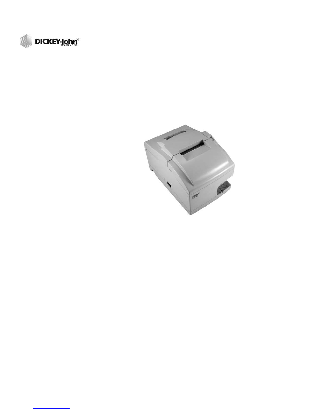
PRINTER
An optional printer that is RS232 compatible or a USB printer that supports
Printer Control Language (PCL) can connect to the GAC®2500 to print test
data results to a ticket. The ticket can be setup to include the facility name
and address, product, date and time, sample ID, customer ID, grain
calibration date, percent moisture, grain temperature, test weight, and
errors. The data can be automatically prin te d at th e en d of eac h
measurement cycle or manually initiated by pressing the Printer button.
Figure 3
Printer
6/INTRODUCTION
GAC® 2500 Model (INTL)
11001-1655B-201611

OPERATOR’S MANUAL
Shipping bracket
on each side wall
Slide bracket
forward
Align with
operation
location
QUICK START GUIDE
This section details the basic steps of setup and analyzing using the GAC
2500 INTL instrument. Refer to other sections of this manual for more
detailed instructions.
STEP 1: UNLOCK SHIPPING BRACKETS
Two shipping brackets must be unlocked prior to setup and operation.
1. Remove the Allen wrench from upper foam
insert.
2. Remove grain drawer and place unit on
backside to locate shipping brackets on the
left and right side walls. IMPORTANT: Be
careful when placing unit on backside to
avoid damage to security switch.
3. Loosen and then remove hex bolt.
4. Press down on the bracket to release.
5. Slide bracket forward and align with
operation location.
GAC® 2500 Model (INTL)
11001-1655B-201611
QUICK START GUIDE / 7

OPERATOR’S MANUAL
Region
CA
DE
US
Set Region
Set Language
Language
Keyboard Style
.
QWERTY
Standard
Language
Dansk
Deutsch
English
Espanol
Francais
Italiano
Thank you for purchasing your GAC2500-INTL
from DICKEY-john. The next screens will take you
through some basic setup steps for your new
GAC2500-INTL.
Ok
X
6. Insert hex bolt into operating location
hole and tighten using the Allen wrench.
7. Perform the same procedure to the
other bracket.
8.Once both brackets are tightened to the
operating location, place unit upright.
STEP 2: INSTRUMENT PLACEMENT
• Place instrument in a clean environment protected from rapid changes
in ambient temperature and vibration.
• A flat, level surface that does NOT exceed more than 1 degree of tilt
(left to right and front to back) is required.
• Surface should be vibration free.
STEP 3: LEVELING INSTRUMENT
A bubble level located on the top surface aids in leveling the instrument for
optimum test weight measurement.
– Adjust the feet (4) on instrument bottom until bubble is in the center
of the level.
NOTE: This step does not occur after
initial setup but both screens
are available by pressing the
System button and selecting
the Region and/or Language
buttons.
STEP 4: INITIAL SETUP
When powered on for the first time, the instrument will force the selection of
the desired region and language. These screens automatically appear.
1.Highlight the desired
Language press Enter.
2.Press OK button.
3.Highlight the Region and
press Enter.
4.The instrument will
proceed with setup and
then proceed to Main
Menu.
8/QUICK START GUIDE
GAC® 2500 Model (INTL)
11001-1655B-201611

OPERATOR’S MANUAL
Instrument
Information
DICKEY-john Co rporation
DICKEY-john Co rporation
Analyze
Current User: UserName
SetupResults
Power
O
Select Pro duct
Select Pro duct
Durum Wheat
Corn-2100
Corn
6-Row Bar ley
2-Row Bar ley
Product
DOWN
UP
Select Pro duct
Select Pro duct
More
Initiate button
CORN
SOYBEANS
WHEAT WINTER
WHEAT RED
Select a
dierent
region
STEP 5: BEGIN GRAIN ANALYSIS
The Main Menu screen appears
after all Startup screens have
loaded. This is the “Home” menu
through which all other menus are
accessed.
1. Press the Analyze button to
begin product selection.
STEP 6: SELECT A PRODUCT
NOTE: If User ID is enabled, it must be
entered before analysis can
occur. Refer to Analyzing Grain
section (Figure 53).
To Select a Grain for Testing:
1. A pre-defined list of 4 grains
appear on the Select Product
screen.
– Grains are saved in a “last used”
order.
–A grain selected on the first
Select Product screen proceeds to
Sample ID screen or the Analysis
screen.
2. To view additional grains not
viewable on the top level Select
Product screen, press the More
button.
–Press the Up and Down buttons
to view grains.
–Select the desired grain in the
product table.
–Once selected, press the Initiate
button to accept.
3. Grain is ready for analysis.
GAC® 2500 Model (INTL)
11001-1655B-201611
QUICK START GUIDE / 9
OPERATOR’S MANUAL
Enter Sample ID
Enter Sample ID
Sample ID
Change Product
View Last Result
Product : Corn
Issue ID: 070109
Customer ID
Sample Id:
Customer Id :
GAC2500-U
Analyzing Corn
Analyzing Corn
Please wait ...
SampleID: “Sample ID”
Initiate Button
Analysis Results
Analysis Results
Product: Corn
Sample Name: Sample ID
10.9% Moisture
25.2 lb/bu
75.0 F
Enter Sample ID
Change Product
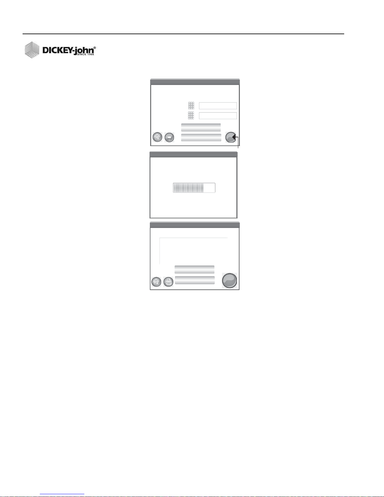
STEP 7: PERFORM A GRAIN ANALYSIS
NOTE: Drawer capacity holds
approximately 3 tests. After 3
tests the drawer must be
emptied before proceeding.
1. If enabled, the Enter Sample
ID screen appears. The selected
product and Issue ID displays at
the top of the screen.
–Change Product button allows
selection of a different product.
–Dump button dumps product
from the hopper.
2. A Sample ID name can be
entered by pressing the keypad
located next to the input box.
3. A Customer ID can be entered
by pressing the keypad located
next to the input box.
4. Press the Initiate button to
proceed.
5. Pour grain into the hopper
heaping grain slightly up to the
hopper full sensors.
6.Press the Initiate button
(green) to begin test. Grain
dumps into the measurement cell
from the hopper. A test will only
perform when the Initiate button
is green.
7.The cell fills and the striker arm
swings across the top of the test
cell to wipe away excess grain.
8. During analysis, a testing
status bar indicates progress.
9. An audible alarm indicates when test is complete and automatically
advances to the Analysis Results screen.
10. The Analysis Results screen displays:
–Product tested
– Sample name
– Moisture content % (* indicates certified)
– Test Weight lbs/bu or kg/hl (optional) (* indicates certified)
– Temperature (optional)
10/QUICK START GUIDE
GAC® 2500 Model (INTL)
11001-1655B-201611

OPERATOR’S MANUAL
Shipping bracket
on each side wall
PHYSICAL INSTRUMENT SETUP
UNLOCK SHIPPING BRACKETS
The GAC® 2500 instrument contains (2) shipping brackets that secure the
measurement cell during shipping. After unpacking the instrument, the
shipping brackets must be unlocked and placed in the operating location
before proceeding to setup and operation.
To unlock shipping bracket:
1. Remove Allen wrench from upper foam packaging insert.
Figure 4
Remove Allen Wrench
2. Carefully remove unit from packaging and place on a flat, sturdy
surface.
3. Remove grain drawer and set aside.
4. Place unit on its backside. IMPORTANT: Be careful when placing
unit on back to avoid damage to security switch. Ship ping brackets
are located on the left and right side wall.
Figure 5
Remove Grain Drawer and Locate Shipping Brackets
5. Loosen hex bolt from the shipping locked location.
GAC® 2500 Model (INTL)
11001-1655B-201611
PHYSICAL INSTRUMENT SETUP / 11

OPERATOR’S MANUAL
Figure 6
Loosen Hex Bolt from Bracket
6. Remove hex bolt and set aside.
Figure 7
Remove Hex Bolt
12/PHYSICAL INSTRUMENT SETUP
7. Press down on the bracket to release.
Figure 8
Press Down on Bracket
GAC® 2500 Model (INTL)
11001-1655B-201611

OPERATOR’S MANUAL
8. Slide bracket forward and align with operating location.
Figure 9
Slide Bracket Forward
9. Insert hex bolt into operating location hole and securely tighten using
the Allen wrench.
Figure 10
Insert Hex Bolt and Tighten
GAC® 2500 Model (INTL)
11001-1655B-201611
10. Perform the same procedure to the other bracket.
11. Once both brackets are securely tightened to the operating location,
place unit upright.
IMPORTANT: If for any reason this unit is shipped or
transported, the hex bolts should be removed from the
operating location and secured back to the shipped locked
location to protect the measurement cell during transit!
PHYSICAL INSTRUMENT SETUP / 13

OPERATOR’S MANUAL
INSTRUMENT PLACEMENT
Place the instrument in a clean environment that is protected from rapid
changes in ambient temperature and vibration. Avoid a hazardous
(classified) location as defined in Article 500 of the NFPA Handbook of the
National Electrical Code.
• Instrument should be placed on a flat, level surface that does NOT
exceed more than 1 degree of tilt (left to right and front to back).
CAUTION: A surface that exceeds this requirement can effect
measurement results.
• Surface should be vibration free.
CAUTION: Vibration from other machines or devices can
effect measurement results.
LEVELING INSTRUMENT
A bubble level located on the top surface of the instrument aids in leveling
the instrument for optimum test weight measurement.
– Adjust the feet (4) on instrument bottom until bubble is in the center
of the level.
14/PHYSICAL INSTRUMENT SETUP
GAC® 2500 Model (INTL)
11001-1655B-201611

OPERATOR’S MANUAL
Secure
Printer
Port
Connection
Security
Switch
Unsecure
SECURITY
NOTE: GAC 2500-INTL instruments
are shipped in unsecure mode.
A security switch is located on the outside back panel. The security switch,
when enabled, allows limited access to screens in accordance with
government requirements. Buttons appear grey for those screens not
accessible.
Some top menu buttons, i.e. System, provide access to the menus but
certain functions within that menu are not accessible.
IMPORTANT: Some INTL machines are also equipped with a seal that
covers the security switch. Check with DICKEY-john
Technical Support group or your local service center
before breaking the seal. When the switch is toggled
from secure to unsecure, an event is logged into
memory for traceability.
To Change Security Switch Position:
The security switch is located below the printer port connection. A
protective brace is secured over the switch with (2) screws that must be
removed to toggle the switch.
Figure 11
Security Switch Location
NOTE: When the switch is toggled
from secure to unsecure, an
event is logged into memory for
traceability.
GAC® 2500 Model (INTL)
11001-1655B-201611
1. Use a screwdriver to remove screws holding brace.
2. Remove brace and screws and set aside.
3. Toggle switch to desired secure or unsecure position.
4. F lip br ac e to th e op po sit e dir ec tio n an d re ins tall over the switc h.
5. Insert screws to hold brace into position over switch.
The instrument does not require a restart when the security switch is
changed.
IMPORTANT: It is recommended to reattach the brace to avoid
unwanted security switch adjustme n t.
SECURITY / 15

OPERATOR’S MANUAL
16/SECURITY
GAC® 2500 Model (INTL)
11001-1655B-201611

OPERATOR’S MANUAL
16.9”
18.6”
10.5”
16.2”
18.6”
13.9”
SIDE VIEW
FRONT VIEW
TOP VIEW
INSTALLATION
The GAC® 2500 unit requires minimal setup. The unit is fully assembled
and ready for operation after att achin g the AC power cor d and inser ting the
grain drawer.
NOTE: After unpacking, visually
inspect for damage occurring
during transit. Save all packing
materials until inspection is
complete. If damage is found,
file a claim with the carrier
immediately and notify your
DICKEY-john sales
representative.
Figure 12
Unit Dimensions
GAC® 2500 Model (INTL)
11001-1655B-201611
CONNECTING AC POWER
1. Securely connect power cord into the AC plug connection (Figure 2)
located on the back of the unit.
2. Plug the male end into an appropriate 3-wire (grounded) outlet.
The grounding pin on the line cord connects directly to the
GAC®2500 frame. When using an adapter ensure the
grounding wire is connected properly to a good earth ground
to prevent a shock hazard.
INSTALLATION / 17

OPERATOR’S MANUAL
Bottomles
Grain Drawer
GRAIN DRAWER
The unit is equipped with a standard grain drawer with handle. An optional
bottomless grain drawer is available for purchase from DICKEY-john.
OPTIONAL BOTTOMLESS GRAIN DRAWER
Part Number: DRAWEROPGAC2500
A bottomless grain drawer is used with a flow-through work counter that
allows the tested grain samples to fall through to a larger container below.
The size of the hole must be at least equal to the drawer dimension and
located directly beneath the grain sample drawer.
NOTE: Contact DICKEY-john Europe
at 33 1 41 19 21 81 for
additional information on grain
drawers.
Figure 13
Flow Through Work Counter
18/INSTALLATION
GAC® 2500 Model (INTL)
11001-1655B-201611

OPERATOR’S MANUAL
Region
CA
DE
US
Set Region
Set Language
Language
Keyboard Style
.
QWERTY
Standard
Language
Dansk
Deutsch
English
Espanol
Francais
Italiano
Thank you for purchasing your GAC2500-INTL
from DICKEY-john. The next screens will take you
through some basic setup steps for your new
GAC2500-INTL.
Ok
X
INITIAL SETUP
When powered on for the first time, the GAC 2500-INTL instrument will
force the selection of the desired region and language . These screens
automatically appear.
1. Select the Language by highlighting and press Enter.
2. Select the Region by highlighting and press Enter.
The instrument proceeds with setup and the desired settings selected.
This step does not occur after initial setup but both screens a re available by
pressing the System button and selecting the Region and/or Language
buttons.
Figure 14
Set Region and Language
GAC® 2500 Model (INTL)
11001-1655B-201611
INITIAL SETUP / 19

OPERATOR’S MANUAL
20/INITIAL SETUP
GAC® 2500 Model (INTL)
11001-1655B-201611

OPERATOR’S MANUAL
Enter Sample ID
Enter Sample ID
Sample ID
Load Sample
Change Product
View Last Result
Product: Corn
Issue ID:
Customer ID
Sample ID
Customer ID
1
2
3
4
05182006
GAC2500-UGMA
NAVIGATION
The user interacts with the GAC® 2500 via the LCD touch screen display.
Screen interaction by finger touch or using a dull, pointed object, such as a
stylus or pen is recommended.
Refer to Maintenance section for cleaning display.
Do not use any sharp objects on the display. Damage to screen
can result.
The following methods allow navigation through and interface with the unit:
1. Text input boxes
2. Keypad icon (enables keyboard)
3. Buttons
4. Keyboard
GAC® 2500 Model (INTL)
11001-1655B-201611
Figure 15
LCD Touch Screen Display
USING EXTERNAL DEVICES
The following external devices can be used to enter data and navigate
through the screens by connecting to the USB ports (2 front/2 back):
• keyboard
•mouse
• barcode scanner
TOUCH SCREEN BUTTON FUNCTIONS
HOME
Home button is available on most screens and, when pressed, returns to
the Main Menu screen.
NAVIGATION / 21

OPERATOR’S MANUAL
POWER OFF
Power Off button turns the system off from the touch screen display. The
system must be turned on using the On/Off button locate d on the front panel
but can be turned off from either the screen display or the On/Off button.
INITIATE
The Initiate button is used to analyze grain and has 3 states of operation:
Green = proceed to begin test
Yellow = an action is required to proceed
Red = system cannot process; error has occurred
PRINT
Print button allows printing test results to a local printer. Refer to the Setup
section for print requirements.
BACK
Back button returns to the previous screen.
ABORT
Abort button dumps grain from hopper, empties the cell, and aborts test.
ENTER
Enter button accepts action taken and proceeds to next screen.
USB
USB button is used when connecting the unit direct to a computer for
downloading software and installing calibrations.
USER
User button appears on the Main Menu screen only if a User ID has been
enabled in System Setup. Requires a tester to enter a User Name before a
grain analysis can proceed and will print on a ticket.
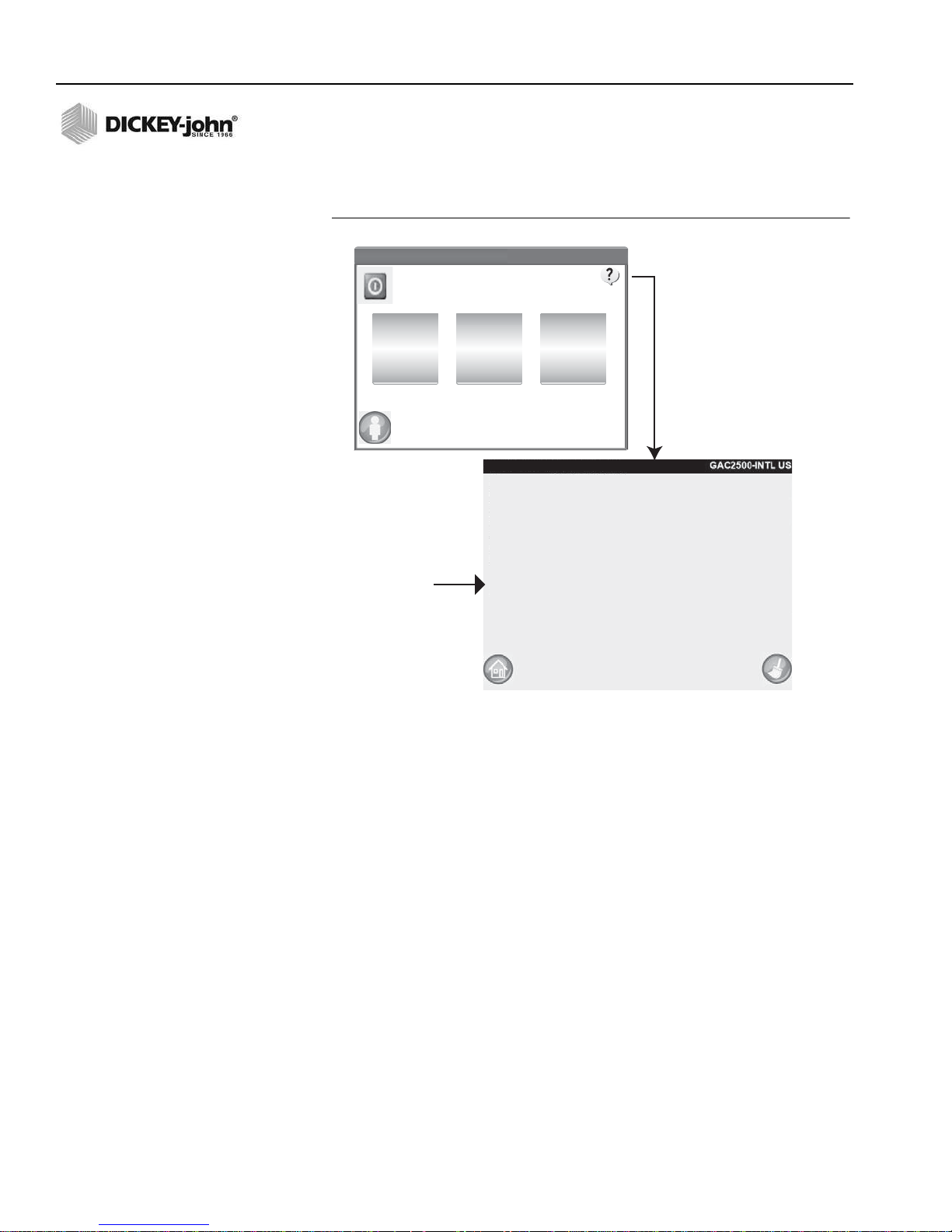
INSTRUMENT INFORMATION
Instrument Information button appears on the Main Menu screen
providing details regarding unit service date, serial number, and software
version. Typically used for troubleshooting purposes.
22/NAVIGATION
LCD DISPLAY TOUCH SCREEN CALIBRATION
Display Touch Screen Calibration button re-calibrates the dis pla y whe n
screen responsiveness does not occur ef fectively to a finger touch or stylus.
This button is located at the System Setup Service menu.
GAC® 2500 Model (INTL)
11001-1655B-201611

OPERATOR’S MANUAL
GAC2500-UGMA
+
X
KEYPAD
The Keypad icon appears on those scree ns that require text entry.
Pressing the Keypad icon opens the virtual keyboard for typing text in
English on the screen. The virtual keyboard is used when an external
keyboard, mouse, or bar code scanner are not available.
Figure 16
Keyboard
CLEAN
Clean button appears on the Instrument Information screen and allows
cleaning the cell and door using an automated process. During the cleaning
sequence, the hopper door automatically op en s.
REGION
Region button navigates to the Region screen and allows selection of a
different region.
IMPORT REGION
Import Region button adds a new region to the instrument via USB
memory device at the Region screen.
DELETE REGION
Delete Region button removes a region from the instrument at the Region
screen.
GAC® 2500 Model (INTL)
11001-1655B-201611
NAVIGATION / 23

OPERATOR’S MANUAL
24/NAVIGATION
GAC® 2500 Model (INTL)
11001-1655B-201611

OPERATOR’S MANUAL
PASSWORD RESTRICTIONS
NOTE: Some functions are not
available when the security
switch is set to Secure mode
due to governmental
regulations and appear in a
gray tone.
NOTE: An external keyboard, bar code
scanner, or mouse can be used
to enter data into the unit.
Setting an Admin user name and password to restrict system settings to be
controlled by an administrator are optional. The unit is shipped with an
Admin user name and password setting of “GUEST”.
Keeping the Admin user name and password a s “GUEST” retains the unit in
open access mode allowing any user to enter System Settings and modify
unit settings.
IMPORTANT: To restrict access to System Setup that affects overall
unit functionality , a new Admin u ser name and p assword
must be created.
To Create an Admin User Name and Password:
1. At the Main Menu screen, press the Setup button.
2. Leave the Admin Username and Password as GUEST and press the
Enter button.
3. At th e Set up scre en , pr es s the Admin Settings button.
4. At the Enter New Password screen, press the Admin Username
keypad icon and enter an administrator user name.
5. Press the Enter button to accept.
6. Enter a Password and re-enter password to confirm.
7. Press the Enter button to accept.
Once a new password is created, the unit is configured so that an
administrator name and password is required to gain entry into the System
Setup screens. Password and User Name can be any combination of
letters and numbers.
Refer to Administrative Settings in the System Settings section to change
an Administrator user name and password or reset to open access.
GAC® 2500 Model (INTL)
11001-1655B-201611
IMPORT ANT: The following words should be not used as User Names:
(ROOT, GUEST, REBOOT, RESET).
PASSWORD RESTRICTIONS / 25

OPERATOR’S MANUAL
System
Setup
Setup
Admin Settings
Enter New Password
FRED
New Password
Re- Enter Password
FRED PASSWORD
FRED PASSWORD
Enter Admin Username
GAC2500-UGMA
Enter Admin Username
Enter Admin Username
Enter Admin Username
GUEST
GUEST
Enter Password
Please Log In
GAC2500-UGMA
Product
Diagnostics
GAC2500-UGMA
Enter Admin Username
Figure 17
Password Screen
26/PASSWORD RESTRICTIONS
GAC® 2500 Model (INTL)
11001-1655B-201611
OPERATOR’S MANUAL
System
Setup
GAC2500-UGMA
Setup
Admin Settings
Product
Diagnostics
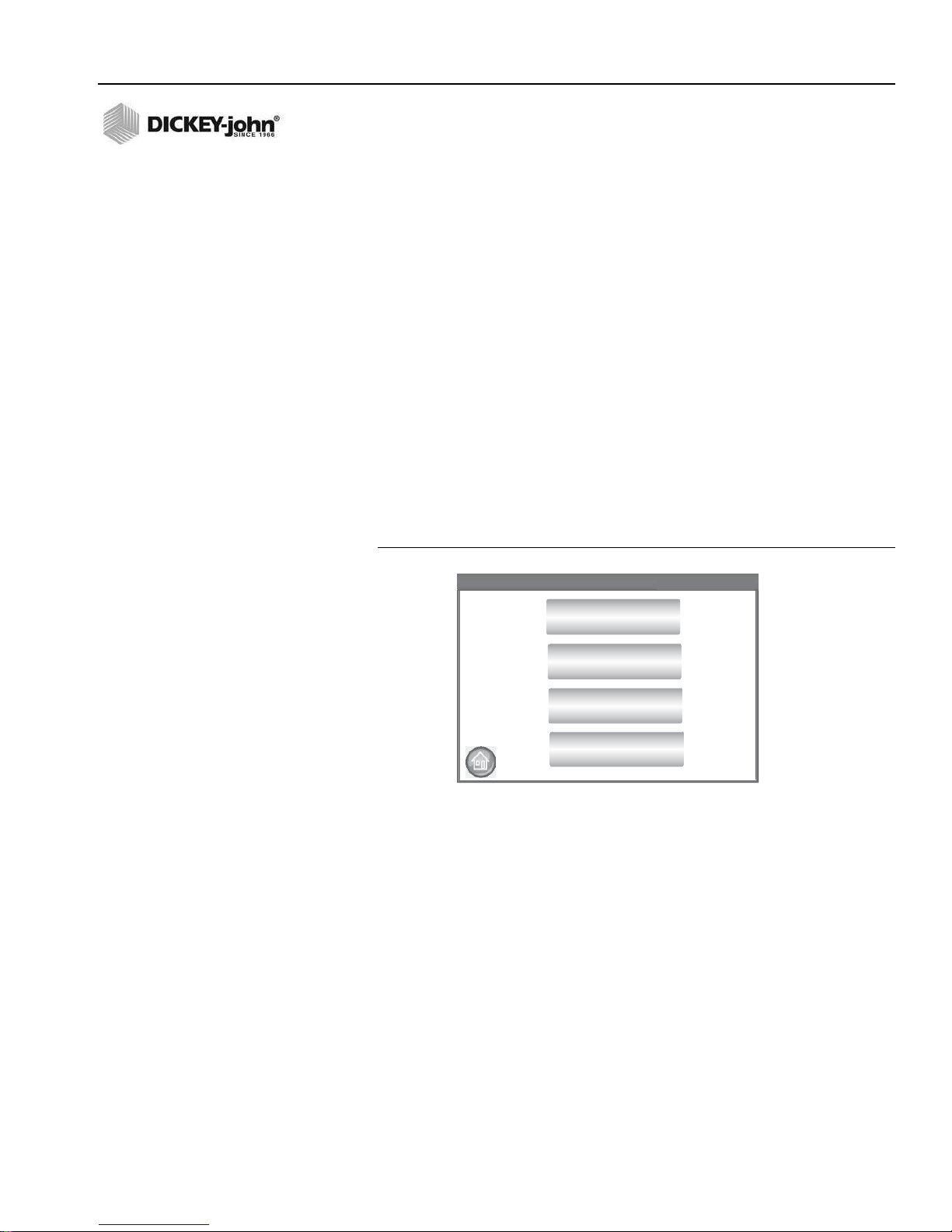
SETUP
NOTE: Some functions are not
available when the security
switch is set to Secure mode
due to governmental
regulations and appear in a
gray tone.
Setup establishes basic unit operating parameters and allows
customization of the user interface by:
• Editing an existing product and loading new products (Product button)
• Setting administrative levels (Admin Settings bu tt on )
• Setting system parameters for external devices, language/loca l e
preferences, time/date, sample result output, unit measurement,
sample/customer ID’s, delete records, and printing formats (System
button)
• Diagnostics for troubleshooting and unit information (Diagnostic
button)
To View Setup Options:
1. At the Main Menu screen, press the Setup button.
2. Enter User Name and Password, if required, and press the Enter
button to display the Setup screen. If defaulted to Name (Guest) and
Password (Guest) press the Enter button.
Figure 18
Setup Screen
NOTE: Official calibrations are
regulated and cannot be
altered.
GAC® 2500 Model (INTL)
11001-1655B-201611
PRODUCT
The Product screen is used to:
• Edit existing products
• Load new products
EDIT EXISTING PRODUCT
If for any reason non-official calibrations need adjustment, certain product
parameters can be changed as follows:
• Modifying moisture and test weight bias and moisture and test weight
slopes
• Creating a new product by copying a similar product (duplicated and
saved using a different name and Issue ID)
• Deleting an existing product from appearing on active screens
SETUP / 27

OPERATOR’S MANUAL
Produ ct Setup
Produ ct Setup
Edit Existing Product
Load New Product
Load New Products
Only appears
if ash drive
is inserted
into unit or
is not in
Security mode.
View Produ ct Setup
View Produ ct Setup
DOWN
UP
LGR Rice
HRW Wheat
HRS Wheat
Corn
6-Row Barley
Product
GAC2500-UGMA
GAC2500-UGMA
Region
button
NOTE: Calibrations are dictated
by the local governing agency
and may vary by region.
To Edit an Existing Product:
1. At the Product Setup screen, press the Edit Existing Product button.
– At the View Product Setup screen an alphabetical product list
appears. Press the Up or Down button to display additional
products.
– Press the Region button to select a different region.
Figure 19
Edit Existing Product Screens
28/SETUP
2. Press the desired product to highlight and press the Enter button to
select. Once the product is selected, the product’s parameters display
in a table.
3. Select the desired action:
– Edit product (does not display on screen for official calibrations)
– Create product
– Delete produ ct
GAC® 2500 Model (INTL)
11001-1655B-201611

OPERATOR’S MANUAL
View Produc t Setup
View Produc t Setup
Delete
Edit
Create
Product: Peas2100
Issue ID: 20101231
Calibration: GAC2100 Emulation
Range: 10 - 30% Moisture
Test Weight Range: 42 -73 lbs/bu
Temperature Range: 0 -50° C
Moisture Bias: 0.00
Moisture Slope: 1.00
Test Weight Bias: 0.00
Test Weight Slope: 1.00
File Name: Peas2100.cal
Edit button
is not available
for NTEP
calibrations
Edit Prod uct
Edit Prod uct
0.02
0.99
0.10
0.99
Moisture Bias
Moisture Slope
Test Weight Bias
Test Weight Slope
GAC2500-UGMA
Produ ct Already Exists
Produ ct Already Exists
Skip
Replace
Product Already Exists
Peas2100
GAC2500-UGMA
EDIT PRODUCT
A product’s moisture bias, test weight bias, moisture slope, and test weight
slope can be changed at this screen. All official calibrations are locked and
cannot be modified. A product’s calibrations should only be changed by an
authorized user .
NOTE: A product’s detail at the View
Product Setup screen can be
printed by pressing the Print
button.
NOTE: An external keyboard, bar code
scanner, or mouse can be used
to enter data into the unit.
To Edit a Product:
1. At the View Product Setup screen, press the Edit button.
2. At the Edit Product screen, press the keypad icon to modify a product’s
parameters.
3. When finished, press the Enter button.
4. Confirm product replacement by pressing the Replace button at the
Product Already Exists screen. The Skip button returns to the previous
product’s bias and slope setting.
5. The new bias and slope appears in the product table on the View
Product Setup screen. The product name and Issue ID will remain the
same.
Figure 20
Edit Product
GAC® 2500 Model (INTL)
11001-1655B-201611
SETUP / 29

OPERATOR’S MANUAL
View Produ ct Setup
View Produ ct Setup
Delete
Edit
Create
GAC2500-UGMA
Product: Popcorn
Issue ID: 20101030
Calibration: UGMA
Range: 5 - 35% Moisture
Test Weight Range: 42-68 lbs/bu
Temperature Range: - 25 - 125° F
Moisture Bias: -1.35
Moisture Slope: 1.00
Test Weight Bias: 0.00
Test Weight Slope: 1.00
File Name: POPCORN -20101030.CAL
Rename Pro duct
Rename Pro duct
New Product Name
Popcorn NEW
New Issue ID
20100116
Enter New Product Name
GAC2500-UGMA
CREATE PRODUCT
A new product can be created by copying a similar product’s parameters.
Creating a new product name and Issue ID prevents an existing product’s
parameters from being overwritten.
NOTE: An external keyboard, bar code
scanner, or mouse can be used
to enter data into the unit .
NOTE: Some functions are not
available when the security
switch is set to Secure mode
due to governmental
regulations and appear in a
gray tone.
To Create a Product:
1. At the View Product Setup screen, press the Create button.
2. At the Rename Product screen, the product name and NEW appears
as the default name.
3. Press the keypad icon to enter a different product name, if desired.
4. A new Issue ID is automatically defined for the new product. Press the
keypad icon to enter a different Issue ID, if desired.
5. Press the Enter button to save.
IMPORTANT: Non alphanumeric keys cannot be used to create an
Issue ID, Product Name, or Sample ID (examples
include: &, *, /, #).
Figure 21
Creating a Product Screen
30/SETUP
GAC® 2500 Model (INTL)
11001-1655B-201611

OPERATOR’S MANUAL
Delete Prod uct
Delete Produ ct
Confirm Deletion Of
Peas2100
GAC2500-UGMA
View Produ ct Setup
View Produ ct Setup
Delete
Edit
Create
GAC2500-UGMA
Product: Peas2100
Issue ID: 20101231
Calibration: GAC2100 Emulation
Range: 010 - 30% Moisture
Test Weight Range: 42 - 73 lbs/bu
Temperature Range: 0 - 50° C
Moisture Bias: 0.00
Moisture Slope: 1.00
Test Weight Bias: 0.00
Test Weight Slope: 1.00
File Name: Peas2100.CAL
DELETE PRODUCT
A product and its calibrations can be deleted so that it does not appear on
the active user screens. A product and its history is stored in the unit’s
database and can still be viewed on the Audit Trail screen after it has been
deleted.
Deleting a Product:
1. At the View Product Setup screen, press the Delete button.
2. At the Delete Product screen, press the Enter button to confirm
deletion.
Figure 22
Delete Product Screen
GAC® 2500 Model (INTL)
11001-1655B-201611
SETUP / 31

OPERATOR’S MANUAL
Select a Calibration File
Directory Contents
\Hard Disk\
1 Directory, 2 Files Exist
GAC2500-UGMA
PC Communications in Prog ress
Please wait ...
Opening DurumWheat-070109.cal
Produc t Already Exists
Skip
Replace
Product Already Exists
DurumWheat-070109.cal
GAC2500-UGMA
DurumWheat-070109.cal
Corn-20100422N.cal
Product Setup
Edit Existing Product
Load New Product
GAC2500-UGMA
Load New Products
Single tap
to open
directory.
Tap to select/
highlight desired
directory.
LOAD NEW PRODUCT
New product calibrations can be loaded to the GAC® 2500 via a USB
memory device. The Load New Product buttons only appear when a USB
memory device is inserted in the unit.
NOTE: Some functions are not
available when the security
switch is set to Secure mode
due to governmental
regulations and appear in a
gray tone.
NOTE: Contact a DICKEY-john
representative for assistance
with obtaining updated
calibrations or with transferring
data to the unit.
Loading a Single Product:
1. Insert the USB memory device to the unit’s USB port on front panel of
unit.
2. At the Product Setup screen, press the Load New Product button.
3. Navigate to the directory where the product is located, press on the
product name to highlight, and press Enter to begin download. A
progress bar indicates downloading status.
– A single tap is required to select the desired file.
– Pressing “..\” located at the top of the list returns to previous level in
the directory structure.
4. If a product calibration already exists on the instrument, accept the
new calibration by pressing the Replace button or the Skip button to
revert to the existing product.
Figure 23
Load New Product Screen
32/SETUP
GAC® 2500 Model (INTL)
11001-1655B-201611

OPERATOR’S MANUAL
Pro duct S etup
Pro duct S etup
Edit Existing Product
Load New Product
Load New Products
GAC2500-UGMA
Select a Folder of Calibration Files
DOWN
UP
Directory Contents
\Hard Disk\
GAC2500-UGMA
Single tap
to open
directory.
Tap to select/
highlight desired
directory.
US\
3 Directories, 0 Files Exist
Select A Folder of Calibration Files
DOWN
UP
Directory Contents
\Hard Disk\CA\
GAC2500-UGMA
0 Directories, 13 Files Exist
..\
No selection required.
Press Enter
CA\
DE\
Loading Multiple Products:
NOTE: Product calibrations are
available for download at
DICKEY-john’s website.
www.dickey-john.com/products/
Agriculture/Moisture Testing/
INTERNATIONAL/
GAC2500-INTL/Get Support/
Downloads.
NOTE: You must know the directory
where the files are saved as
names do not display.
1. Insert the USB memory device to the unit’s USB port on front panel of
unit.
2. At the Product Setup screen, press the Load New Products button to
load all products from the selected directory of the memory device or
PC.
3. When loading multiple products, navigate through the directory
structure and highlight the directory containing the desired products to
load. A progress bar indicates downloading status.
– A single tap selects the desired directory.
– Pressing “..\” located at the top of the list returns to the previous
level in the directory structure.
4. Press the Enter button to begin download.
5. If product calibrations already exist on the instrument, accept new
calibrations by pressing the Replace button or the Skip button to
revert to the existing product.
Figure 24
Load Multiple Products Screens
GAC® 2500 Model (INTL)
11001-1655B-201611
SETUP / 33

OPERATOR’S MANUAL
Enter Admin Username
Enter Admin Username
Enter Admin Username
FRED
FRED PASSWORD
Enter Password
Please Log In
DICKEY-john Cor poration
DICKEY-john Co rporation
Analyze
Current User: GUEST
SetupResults
GAC2500-UGMA
GAC2500-UGMA
Enter New Password
JOHN
Enter Admin Username
New Password
Re- Enter Password
JOHN PASSWORD
JOHN PASSWORD
Enter Admin Username
GAC2500-UGMA
System
Setup
GAC2500-UGMA
Setup
Admin Settings
Product
Diagnostics
ADMINISTRATIVE SETTINGS
If the instrument is set with an administrator password, the password can be
changed to a different admin user name and/or password.
NOTE: Refer to the Setting Password
Restrictions section for creating
a user name and password.
TO CHANGE A KNOWN USER NAME/PASSWORD
1. At the Main Menu screen, press the Setup button.
2. At the Password Login screen, enter existing user name and
password.
3. Press the Enter button to accept.
4. At the Setup screen, press the Admin Settings button.
5. Press the Admin Settings button to display the Admin Settings
screen.
6. Press the keypad icon and enter a new Admin Username.
7. Enter New Password and re-enter password for verification.
8. Press the Enter button to accept changes.
The new user name and password is saved when the Enter button is
pressed.
Figure 25
Reset User Name and Password
34/SETUP
Contact DICKEY-john Tech Support or a local representative to reset
instrument to open access mode.
GAC® 2500 Model (INTL)
11001-1655B-201611

OPERATOR’S MANUAL
SYSTEM SETUP
System Setup allows customization of the unit’s functionality and print
settings:
NOTE: Some functions are not
available when the security
switch is set to Secure mode
due to governmental
regulations and appear in a
gray tone.
NOTE: Reference the printer’s
specifications for correct
settings.
• Printer/scale setup
• Language selection
• Region selection
• Time and date setup
• Test result setup (automatic, manual return)
• Exporting data format (CSV, Excel)
• Units of measurement
• Sample setup (sample, user ID)
• Owner data (troubleshooting information)
• Service information (technician information)
• Clear database
• Check scale
• Network setup (technician recommended)
• Update instrument (technician recommended)
PRINTER SETUP
A USB or RS232 serial port connection is available to connect a printer that
prints test data result s to a ticket. Streaming data serially is an option when
using the USB printing function.
The ticket can be customized to include details as it relates to facility, date,
time, testing errors, and product results. The unit can be set to automatically
or manually print a ticket at the end of each test.
To Set Printer Settings:
1. At the System Setup screen, press the Printer button.
2. At th e Prin te r Setu p scre en , en able the check box for the type of
connection between the unit and print er:
– RS232 connection using a Null modem cable
– PCL USB when connecting to a PCL USB printer
– Star USB when connecting to an SP712 USB printer
3. For an RS232 connection, select the Baud Rate, Byte Size, Parity, and
Stop Bits that match the printer.
4. When sending results to a printer, a Header and Footer can be added
to print on each ticket, if desired. Refer to Adding a Header/Footer
section.
5. Press the Test button to verify that the printer and/or computer and the
unit’s print settings match for proper communication between the
devices.
6. When enabled, Automatically Print Upon Sample Result will print a
ticket at the end of each test.
7. When enabled, Include Line Feeds After Print allows additional line
feeds to be added at the end of each ticket after printing.
8. Streaming data serially sends data serially when USB is selected.
Refer to the Streaming Data Serially selection.
GAC® 2500 Model (INTL)
11001-1655B-201611
SETUP / 35

OPERATOR’S MANUAL
Printer Setup
Printer Setup
9600
Baud Rate
1
Stop Bits
8
Byte Size
None
Parity
PRN21
Output Format
Header
RS232 Star USB Printer
CR
Line Termination
PCL USB Printer
Automatically Print Upon Sample Result
Number of New Lines After Print
7
Print CSV Serially Also
CSV Verbose
Always Stream Data Serially
System Setup
System Setup
Printer
Language
More
Region
GAC2500-UGMA
GAC2500-UGMA
Footer
Test
NOTE: When printing to a database
using an RS232 connection
and CSV printer output format,
a line feed of 1 is required for a
carriage return/line feed.
9. Select the output format.
– PRN20 - Standard 20 column printer output
– PRN21 - Special 20 column printer output
– PRN80 - Standard 80 column printer output (80 characters per line)
– PRN81 - Standard 80 column printer output (81 characters per line)
– PTB - A custom region-based format to meet governing body
formats
– CSV01 - Comma separated variables (requires a 9600 baud rate)
selected when test results are sent to a computer.
– NTEP- A custom format for federal agencies
– AUTO - A custom format for federal agencies.
10. Select the line termination style.
– CR - Carriage return
– CRLF - Carriage return, line feed
– LF - Line feed
– LFCR - Line feed, carriage return
Figure 26
Selecting a Printer Type
36/SETUP
GAC® 2500 Model (INTL)
11001-1655B-201611

OPERATOR’S MANUAL
Edit Printer Header
Edit Printer Header
Miller Grain Elevator
Custom Information
Owner Specific Data
GAC2500-UGMA
Entered at
Owner Data
screen
72 Depot Road
Anytown, IL USA
ADDING A HEADER AND FOOTER TO TICKET
NOTE: An external keyboard, bar code
scanner, or mouse can be used
to enter header and footer
information.
Header and Footer text can be added to print on a print ticket. Owner Data
text can be selected as the default or customized text can be entered.
To Enter a Header/Footer:
1. At th e Prin te r Setu p scre en , pr es s the Header button.
2. To use the Owne r Data address information, enab le the check box next
to the company name and address. If the owner dat a text box is bla nk,
owner data information has not been entered at the Owner Data
screen and can be entered at the System Setup screen, Owner Data
button.
3. To enter other text, deselect the Owner Data check box.
4. Press the keypad icon on the screen of the lower text box to open the
unit’s keyboard and enter desired text.
5. Press the Enter button to accept.
6. If desir ed , en te r a fo ote r nam e by pre ssin g the Footer button. Enter
desired information to appear in footer.
Figure 27
Header Screen
GAC® 2500 Model (INTL)
11001-1655B-201611
STREAMING DATA SERIALLY
Streaming data is available in two methods:
Print CSV Serially Also
When only this feature is enabled, CSV data is transmitted out of the serial
port when the Print button is pressed along with a print receipt.
Always Stream Data Serially
When the above “Print CSV Serially Also” is enabled, the optional feature
“Always Stream Data Serially” appears onscreen. With this option enabled,
data is always transmitted serially out the serial port to an external system
whether the Print button is pressed or not.
Both printing and streaming data can be enabled to perform both functions
simultaneously or act independently, if desired.
SETUP / 37

OPERATOR’S MANUAL
Printer Setup
Printer Setup
9600
Baud Rate
1
Stop Bits
8
Byte Size
None
Parity
PRN21
Output Format
Header
RS232 Star USB Printer
LF
Line Termination
PCL USB Printer
Automatically Print Upon Sample Result
Number of new lines after print
7
Print CSV Serially Also
CSV Verbose
Always Stream Data Serially
GAC2500-UGMA
Footer
Test
3
4
Enable Data Streaming:
1. At the System Setup screen, press the Printer button.
2. Select either USB Printer option.
3. To print to a stri p printer and CSV serially, select the “Print CSV Serially
Also”.
4. To always stream data serially after each test, select the “Always
Stream Data Serially” option.
Figure 28
Enable Data Streaming
38/SETUP
PRINTER/SCALE SETUP
The GAC 2500 can be set to print test data results to a ticket via a p rinter as
well as interface with a scale. To interface with a printer and scale certain
parameters must be selected on the Printer Setup screen:
1. At the System Setup screen, press the Printer button.
2. Baud Rate must be set at 9600 to communicate with a scale. At the
Printer Setup screen verify the Baud Rate of 9600 is selected.
– The RS232 checkbox must be selected to view the Baud Rate.
3. To interface with a printer and scale, check either the PCL or Star USB
checkbox.
– When the USB box is checked, the unit can output to both the USB
and RS232 port. The USB port communicates with the printer and
can operate with any printer output format (step 5).
IMPORTANT: When the output desired is to a scale and a printer via
4. To interface with a scale only, check the RS232 box.
USB, Print CSV Serially Also and a Baud Rate of 9600
must be selected.
GAC® 2500 Model (INTL)
11001-1655B-201611

OPERATOR’S MANUAL
5. Select the output format for the printer.
– PRN20 - Standard 20 column printer output
– PRN21 - Special 20 column printer output
– PRN80 - Standard 80 column printer output (80 characters per line)
– PRN81 - Standard 80 column printer output (81 characters per line)
– CSV01 - Comma separated variables (requires a 9600 baud rate)
selected when test results are sent to a computer.
NOTE: When printing to a database or
scale using an RS232
connection and CSV printer
output format, a line feed of 1 is
required for a carriage return/
line feed.
NOTE: Languages are continually
added to this list. Contact a
local DICKEY-john
representative for a complete
list.
6. Select the line termination style.
– CR - carriage return
– CRLF - carriage return, line feed
– LF - line feed
– LFCR - line feed, carriage return
7. When enabled, Automatically Print Upon Sample Result will
automatically print a ticket at the end of each test. When disabled, a
ticket must be manually printed at the end of each test.
8. When enabled, Include Line Feeds After Print allows additional line
feeds to be added at the end of each ticket after printing.
9. Press the Enter button to accept changes.
LANGUAGE AND KEYBOARD SETTINGS
The GAC 2500-INTL is equipped with 22 languages that displays the user
screens in the language selected.
• Brazilian Portuguese
•Chinese
•Croatian
• Czech
•Danish
•Dutch
• English
• Estonian
•French
•German
• Hungarian
• Italian
• Latvian
• Lithuanian
• Polish
• Portuguese
•Romanian
• Russian
• Serbian
• Slovak
• Spanish
• Swedish
GAC® 2500 Model (INTL)
11001-1655B-201611
VIRTUAL KEYBOARD
A keypad icon appears on those screens that require text entry. Pressing
the Keypad icon opens the virtual keyboard for typing text on the screen.
Two keyboard styles are available:
SETUP / 39

OPERATOR’S MANUAL
Enter Sa mple Name
Enter S ample Name
V
UO P Q SR TN
M
G
H IKJ
LF
E0 . A CB D9
82 3 4 65 71
Space
W X Y Z -
GAC2500-UGMA
GAC2500-UGMA
System Setup
System Setup
Printer
Language
Region
More
Set Language
Set Language
Language
Keyboard Style
.
QWERTY
Standard
GAC2500-UGMA
GAC2500-UGMA
Language
Dansk
Deutsch
English
Español
Français
Italiano
DOWN
• Qwerty (default)
• Standard
IMPORTANT: Any text entered using the keyboard appears in English
only.
Figure 29
Qwerty and Standard Keyboard Styles
To Select a Language or Keyboard Type:
1. At the System Setup screen, press the Language button.
2. At the Language screen, press the desired language and press Enter.
3. To select a keyboard type, press the radio button to enable either
QWERTY or Standard style.
4. Unit automatically converts to the selected system language and/or the
selected keyboard.
40/SETUP
Figure 30
Language Screen
GAC® 2500 Model (INTL)
11001-1655B-201611

OPERATOR’S MANUAL
Set R
System Setup
System Setup
Printer
Language
GAC2500-UGMA
Set Region
Region
CA
DE
US
Region Updated to CA
Region
More
REGION
NOTE: Some functions are not
available when the security
switch is set to Secure mode
due to governmental
regulations and appear in a
gray tone.
The Region screen displays the list of available regions. Import new regions
to the instrument via a USB memory device. An instrument’s current regi on
setting can be found at the Instrument Information screen and the Region
screen.
To Select a Region:
1. At the System Setup screen, press the Region button.
2. A list of installed regions appear on the Set Region screen. Highlight
the desired region and press the Enter button.
– A region with an ‘*’ indicates no calibrations exist for that region.
3. ‘X’ button deletes the highlighted region calibrations and .ini files. Only
press this button to remove the region files from the instrument.
Figure 31
Setting Region
GAC® 2500 Model (INTL)
11001-1655B-201611
SETUP / 41
OPERATOR’S MANUAL
DICKEY-john Co rpo ration
DICKEY-john Co rpo ration
Analyze
Current User: GUEST
SetupResults
GAC2500-UGMA
Instrument Information
Model: GAC 2500-INTL
S/N: 1807-00047
Software Version: 5.1.0.1, 2.5, 2.2
IP Address: 169.254.0.94, 131.171.2.54
Last Service: 1/1/2016
App Sum:
I/O Sum:
Region: DE
Region, Certication
and Directive vary
by region based on
the governing
body
4. Press the Ok button to acknowledge region change. The active region
is also noted on the Instrument Information screen.
Figure 32
Instrument Information Screen
42/SETUP
GAC® 2500 Model (INTL)
11001-1655B-201611

OPERATOR’S MANUAL
Set R
\HARD DISK\
\HARD DISK\\CA
Import
Set Region
Region
Import Region
..\
CA\
Import Region
IMPORT A REGION
Regions and corresponding calibrations can be imported to the instrument
via a USB memory device at 2 different screens: Set Region and Products.
NOTE: Empty regions with no
calibration files are marked with
an ‘ * ’ .
NOTE: Some functions are not
available when the security
switch is set to Secure mode
due to governmental
regulations and appear in a
gray tone.
To Import a Region at the Set Region Screen:
1. Insert USB memory device with stored region.ini file and calibrations.
2. At th e Syst em Setup m en u, press th e Region button.
3. At the Set Region screen, select the desired region and press the ‘+’
Import button. The Import button is visible only when a USB memory
device is inserted.
4. Select to highlight the Region.ini file and press the Enter button.
5. Calibrations will download to the instrument. Upon completion the new
Region will appear on the Region screen as a selectable item.
Figure 33
Import a Region
GAC® 2500 Model (INTL)
11001-1655B-201611
SETUP / 43

OPERATOR’S MANUAL
Prod uct Setup
Prod uct Setup
Edit Existing Product
Load New Product
Load New Products
GAC2500-UGMA
Select a Folder of Calibration Files
DOWN
UP
Directory Contents
\Hard Disk\
GAC2500-UGMA
Single tap
to open
directory.
Tap to select/
highlight desired
directory.
US\
3 Directories, 0 Files Exist
Select A Folder of Calibration Files
DOWN
UP
Directory Contents
\Hard Disk\CA\
GAC2500-UGMA
0 Directories, 13 Files Exist
..\
No selection required.
Press Enter
CA\
DE\
IMPORT REGIONS AT PRODUCT SCREEN
1. Insert a USB memory device with stored region.ini file and calibrations.
2. At the Setup screen, press the Product button.
3. Press the Load New Products button.
4. Select the desired region found in the Directory Contents window and
press Enter button.
5. Press the Enter button again to begin download.
Figure 34
Import Regions at Product Screen
44/SETUP
DELETE A REGION
Deleting a region from the instrument removes the region file and all
associated calibration files.
To Delete a Region:
1. At the System Setup screen, press the Region button.
2. At the Set Region screen, highlight the Region to delete.
3. Press the ‘X’ delete button.
4. Press Yes to remove files or No to abort.
GAC® 2500 Model (INTL)
11001-1655B-201611

OPERATOR’S MANUAL
Set R
Set Region
Region
CA
DE
US
Delete
Import
Your Response Needed
Are you sure you want to delete region “CA”?
Ye s
No
Your Response Needed
Region “CA” already exists. Do you want to replace
it and all of the associated calibrations?
Ye s
No
Figure 35
Delete A Region
IMPORTING EXISTING CALIBRATION/REGION FILES
A warning screen displays if trying to import a region and its calibrations that
currently reside on the instrument.
• Select NO to abort import
• Select YES to override existing files
Figure 36
Importing Existing Calibrations and Region Files
GAC® 2500 Model (INTL)
11001-1655B-201611
SETUP / 45

OPERATOR’S MANUAL
SAMPLE SETUP
NOTE: Some functions are not
available when the security
switch is set to Secure mode
due to governmental
regulations and appear in a
gray tone.
A Sample ID, Customer ID, User Name (Login) can be enabled so that a
grain sample is identified and saved with this informa tion each time a test is
performed.
1. At the System Setup screen, press the the More button until the
Sample Setup button appears.
2. Enable the check box of desired ID’s required when running samples.
3. Press the Enter button to accept.
Prompt for Sample ID
The Sample ID screen step can be hidden so that the screen does not
appear during analysis. If a sample or customer ID is required, “Prompt for
Sample ID”, should be checked.
Prompt for Sample ID can be enabled even when a sample or customer ID
is not required so the screen appears during analysis giving the option to
include either of these ID’s.
– Enable when a sample or customer ID are required entries before
analysis. A sample ID will be associated with each grain test and
prints to ticket.
– Disable to eliminate the Sam p le ID scre e n befo re eac h an a lysis
Automatic Sequence Sample ID
Automatic number sequencing to the next higher number will occur with
additional tests of the same grain. Sequence Sample ID default is enabled.
Reset counter at System Setup/Service Data button.
User Login Required (Sample ID)
Format for federal agencies.
Customer ID Required
Requires a Customer ID to be associated with each gra in te st an d pr ints to
ticket. Customer ID default is disabled.
User Login Required
A User Login requires a tester to login with a user name at the Main Menu
screen before grain can be analyzed. If a user login is required, the user
name entered at the User Login screen is recorded in the unit’s database
and prints on the print ticket. The User button only appears on the Main
Menu screen when enabled. User Login default is disabled.
46/SETUP
GAC® 2500 Model (INTL)
11001-1655B-201611
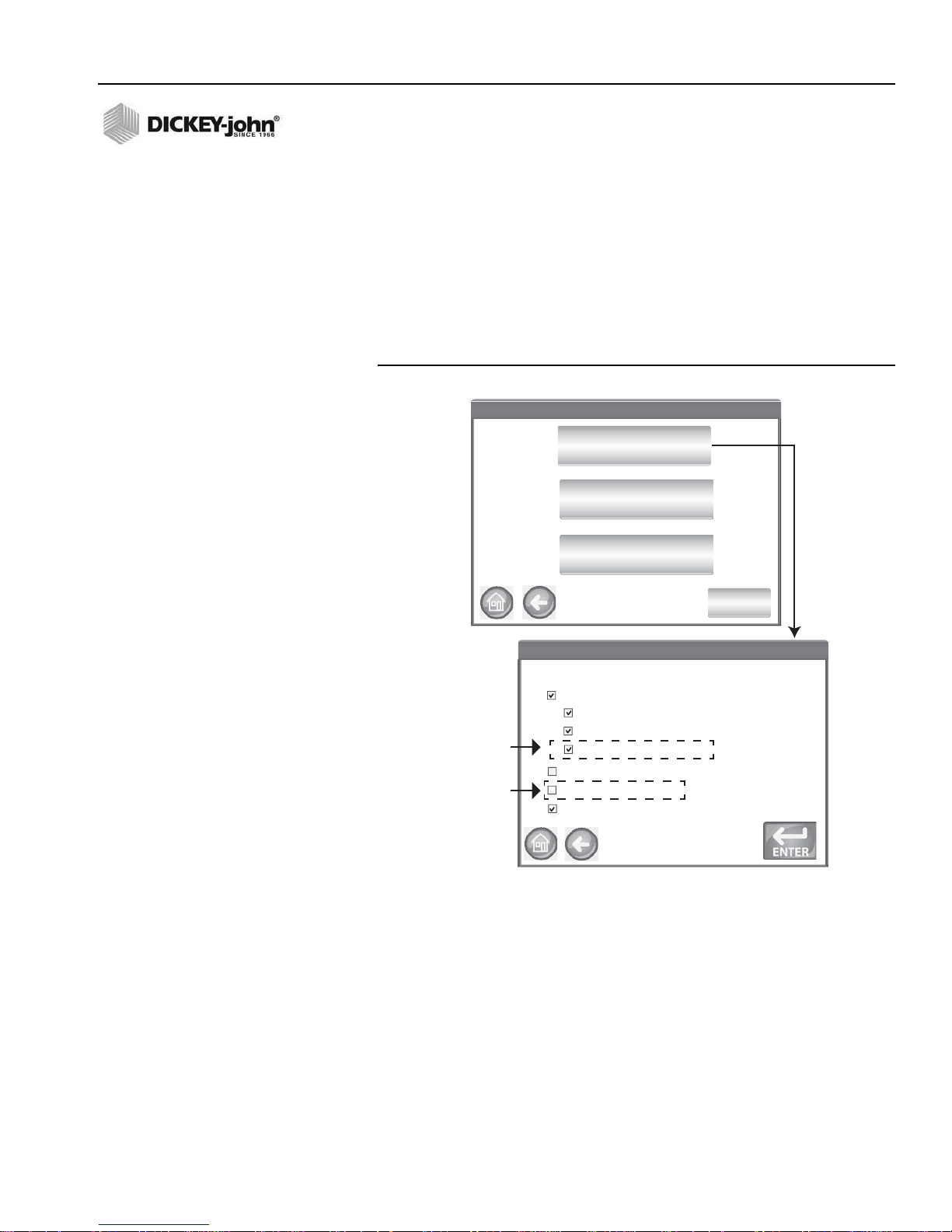
OPERATOR’S MANUAL
System Setup
System Setup
Result Setup
More
Sample Setup
Export Data Format
GAC2500-UGMA
Sampling Setup
When Running Samples:
:
User Login Required
A Sample ID is Required
Auto Sequence Sample ID
A Customer ID is Required
Prompt for Sample ID
Automatically Measure When Hopper is Full
User Login Required
Requires a User
Login at the
Sample ID screen
(Typically used
by federal
agencies)
User Login at
Main Menu
Automatic Measure When Hopper is Full
Instrument automatically proceeds to measure a sample when the hopper is
full eliminating the need to press the Initiate button (green).
– Enable this feature to automate the measuring process. If a Sample
ID or Customer ID is required, analysis automatically starts at the
Sample ID screen. After the ID requirement is met, the
measurement automatically starts.
– Disable this feature to require a manual response at each analysis
screen.
Figure 37
Sample Setup Screen
GAC® 2500 Model (INTL)
11001-1655B-201611
SETUP / 47

OPERATOR’S MANUAL
RESULT SETUP
NOTE: Some functions are not
available when the security
switch is set to Secure mode
due to governmental
regulations and appear in a
gray tone.
After performing a grain analysis, the unit can be set to automatically
advance back to the Sample ID screen from the Analysis Result s scre en or
manually return to this screen with a button press. The unit default is set to
manual return. Grain automatically dumps from the hopper in manual or
automatic advance mode.
To Display the Sample Return Setup screen:
1. At the System Setup screen, press the More button to display and
press the Result Setup button.
2. Select the desired feature to enable.
3. Press the Enter button to save.
Automatic Return
Advances from the Analysis screen to the Sample ID screen within a
specified period of time (4 to 20 seconds) without pressing the Initiate
button.
Manual Return
Advances to the Sample ID screen to perform another test by pressing the
Enter button after each test.
Empty Drawer Requirement
A forced empty of the drawer requires a sample dump before proceeding to
the next analysis.
Bottomless Drawer in Use
Must be enabled when the bottomless drawer style is used with a
flow-through counter to prevent an empty drawer caution from occurring
when running tests.
– Grain can also be tested without the grain drawer secured in the
unit when Bottomless Drawer in Use is enabled; however, a Drawer
Ignored screen appears each time a test is performed and will only
proceed to perform test when the Initiate button is pressed.
48/SETUP
Display Test Weight and Temperature
Displays the test weight and temperature on the Results screen for each
test. Both features are defaulted to enabled.
GAC® 2500 Model (INTL)
11001-1655B-201611

OPERATOR’S MANUAL
Sample Retur n Setup
Sample Retur n Setup
Upon Sample Result::
8
Enter n umber between 4 – 20 seconds
Bottomless Drawer in Use
Seconds before automatic return
Manual Return
Require drawer to be emptied after each sample
Display Test Weight
Display Temperature
System Setup
System Setup
Result Setup
More
Sample Setup
Export Data Format
Figure 38
Result Setup Screen
GAC® 2500 Model (INTL)
11001-1655B-201611
SETUP / 49

OPERATOR’S MANUAL
Saved Data
Saved Data
Save Data Outputs in the Followi ng Format:
CSV Format
Excel Format
GAC2500-UGMA
System Setup
System Setup
Result Setup
More
Sample Setup
Export Data Format
EXPORT DATA FORMAT
Data can be saved for output to a computer in an Excel or CSV format. The
unit default is Excel.
1. At the System Setup screen, press the the More button until the
Export Data Format button appears.
2. Enable the check box of the desired output.
3. Press the Enter button to accept.
IMPORTA NT: A USB memory device less than or equal to 2-4 GB in
size formatted as FAT is recommended for extracting
data from instrument.
Figure 39
Data Format Screen
50/SETUP
GAC® 2500 Model (INTL)
11001-1655B-201611

OPERATOR’S MANUAL
System Setup
System Setup
Time and Date Settings
Time and Date Settings
GAC2500-UGMA
Monday, June 10, 2014
Current Time: 6/10/14/ 6:18:06 PM
More
Units
6
18 06
Time
Owner Data
TIME
NOTE: Some functions are not
available when the security
switch is set to Secure mode
due to governmental
regulations and appear in a
gray tone.
NOTE: The date can be changed to US
or UK format at the Units
screen.
1. At the System Setup screen, press the Time button.
2. To select a date, press the Date drop down arrow to display calendar.
3. Use arrows to change the month.
4. En te r time usin g th e up /d own arrows.
5. Select PM check box, if applicable.
6. Press the Enter button when done.
Figure 40
Time and Date Screen
GAC® 2500 Model (INTL)
11001-1655B-201611
SETUP / 51

OPERATOR’S MANUAL
Units Setup
Units Setup
Date Format:
Temperature:
Radix Point:
Test Weight:
MM/DD/YYYY DD/MM/YYYY
Fahrenheit
Celsius
Period (.) Comma (,)
Lb/bu Kg/hl
Moisture:
X.X X.XX
System Setup
System Setup
More
Owner Data
Units
Time
UNITS
The Units screen allows selection of:
• Date format (US or Euro)
• Temperature (degrees F or C)
• Unit measurement for test weight (lb/bu or kg/hl)
• Radix point (, or .)
• Moisture, test weight, and temperature display resolution (tenths or
hundredths)
Test Weight defaults to display on the Analysis Results screen but can be
removed by disabling at the Sample Setup screen.
NOTE: Instruments with a Region set
to Canada use a Test Weight
reference point based on the
Avery bushel. U.S. instruments
use a Test Weight reference
point based on the Winchester
bushel.
Unit defaults:
Unit defaults are automatically selected based on the instrument’s active
region and will adjust accordingly any time that region is changed.
To Change Units:
1. At the System Setup screen, press the the More button until the Units
button appears.
2. Press the Units button to display the Units Setup screen.
3. Enable the respective check boxes.
4. When selected, press the Enter button to accept.
Figure 41
Units Screen
52/SETUP
GAC® 2500 Model (INTL)
11001-1655B-201611

OPERATOR’S MANUAL
Owner Data
Owner Data
Name:
Address:
DICKEY-john Corp.
Auburn, IL 62615
Phone:
21 7-4 38-3 371
System Setup
System Setup
More
Owner Data
Units
Time
OWNER DATA
Enter name, address, and phone information, if desired. Data entered at
this screen can be used as the header/footer on a print ticket.
This data can also be viewed by pressing the Instrument Information
button found on the Main Menu screen, refer to Printer Setup.
1. At the System Setup screen, press the More button until the Owner
Data button appears.
2. Press the Owner Data button and enter name, address, phone
number by pressing the keypad icon.
3. Press the Enter button when finished.
NOTE: An external keyboard, bar code
scanner, or mouse can be used
to enter data.
Figure 42
Owner Data Screen
GAC® 2500 Model (INTL)
11001-1655B-201611
SETUP / 53

OPERATOR’S MANUAL
System Setup
System Setup
Service Data
Service Data
Service N ote::
Frank from Dj performed inspection
Service D ate:
10 10/ /2015
Res ettabl e Counter::
Total Cycles::
2000
100,000
Clear Database
Check Scale
Service Data
Reset
SERVICE DATA
NOTE: Some functions are not
available when the security
switch is set to Secure mode
due to governmental
regulations and appear in a
gray tone.
NOTE: An external keyboard, bar code
scanner, or mouse can be used
to enter data.
The Service Data screen provides text entry fields for technicians to enter
comments regarding service performed on the unit and service date.
– Resettable Counter resets the number of tests to 0.
– T ot al Cycles indicates the nu mber of tests perform ed over the life of
the unit and is not resettable.
1. At the System Setup screen, press the More button until the Service
button appears.
2. Press the Service Data button to display the Service Data screen.
3. Enter notes and date by pressing the keypad icon.
4. Press Reset button to set counter to 0, if desired.
Figure 43
Service Screen
54/SETUP
GAC® 2500 Model (INTL)
11001-1655B-201611

OPERATOR’S MANUAL
Carefully press and briey hold stylus on the center of the target.
Repeat as the target moves around the screen.
Press the Esc key to cancel.
+
Press Target
with nger
or stylus
New calibration settings have been measured.
Press the Enter key to accept the new settings.
Press the Esc key to keep the old settings.
++
++
Service Data
Service Data
Service Note::
Frank from Dj performed inspection
Service Date:
10 10//2015
Resettable Counter::
Total Cycles::
2000
100,000
Reset
LCD DISPLAY TOUCH SCREEN CALIBRATION
The LCD display touch screen may not respond as it should with a finger
touch or stylus after a period of time or if subjected to extreme temperature
changes. The display can be re-calibrated to improve responsiveness.
1. At th e Ser vice Data screen, pr es s the Display Touch Screen
Calibration button and follow onscreen instructions.
2. Carefully press and hold finger on the center of the target.
3. Repeat as the target moves around the screen.
4. With a keyboard attached, press the Enter button to accept new
settings or the Esc button to keep previous settings. Without an
attached keyboard, press anywhere on the screen to accept.
Figure 44
Display Calibration
GAC® 2500 Model (INTL)
11001-1655B-201611
SETUP / 55

OPERATOR’S MANUAL
Your Response Needed
Your Response Needed
Yes
No
Delete All Results
System Setup
System Setup
Clear Database
Check Scale
Delete Results?
Delete Results?
Delete All Results
2515 Results in Database
Engineering log les present
Delete Engineering Data
Appears if
Engineering
les are present
Service Data
CLEARING A DATABASE
The unit is capable of storing a maximum of 3,000 test results. The
database can be cleared at any time by selecting the Clear Dat abase button
located under the System Setup screen. When stored data has reached
approximately 2,500 records, a warning screen automatically appears when
attempting a grain measurement that indicates memory capacity is getting
low. Analysis can still occur until the maximum allowed records of
approximately 3,000 is reached. Once maximum storage is reached, grain
analysis cannot continue until cleared.
To Delete Records:
1. At the System Setup screen, press the More button until the Clear
Database button displays.
2. Press the Clear Database button to display the Delete Results screen.
3. At the Delete Results screen, press the Delete All Results button.
– A Delete Engineering Data button appears if Engineering log files
are present. This button must be pressed to clear those records.
4. Press Yes to proceed with clearing records.
– Press No to abort record deletion.
NOTE: Instruments with a Region set
to Germany do not delete
records less than 90 days old.
Figure 45
Memory Capacity Low Screen
56/SETUP
GAC® 2500 Model (INTL)
11001-1655B-201611

OPERATOR’S MANUAL
System Setup
System Setup
Service Data
Check Scale
Fill Hopper with Sample
Check Scale
Check Scale
Clear Database
CHECK SCALE
Check Scale performs an instrument scale measurement for a weight
accuracy comparison with an external scale. The readings displayed
onscreen are actual temperature and weight product results.
To Perform a Check Scale:
1. At the System Setup screen, press the More button until the Check
Scale button displays.
2. Press the Check Scale button to display the Check Scale screen.
3. Fill hopper with a sample. When the hopper is full, the next screen
automatically displays.
Figure 46
Performing a Check Scale
GAC® 2500 Model (INTL)
11001-1655B-201611
4. Press the Measure button to start the process.
– This is the last screen that allows returning to the previous screen
or returning to the Home screen.
5. Measurement process automatically begins measuring tare then
loading and weighing the sample.
6. At the Scale Measurement Results screen, dump any excess material
that fell into the drawer during the strike off process. The sample
weight and temperature captured during the measuremen t appears on
this screen.
7. Insert drawer into instrument.
SETUP / 57

OPERATOR’S MANUAL
GAC
Measure Tare.
Check Scale
Check Scale
Loading...
Checking Scale...
Checking Scale...
Weighing.
Checking Scale...
Checking Scale...
Weight = 263.90 g
Temp: 22.72°C
Please Empty Drawer
Scale Measurement Results
Scale Measurement Results
Scale Measurement Results
Scale Measurement Results
Weight = 263.90 g
Temp: 22.72°C
Please Close Drawer
Press Measure to Read Scale
Check Scale
Check Scale
Measure
Figure 47
Performing a Check Scale
58/SETUP
GAC® 2500 Model (INTL)
11001-1655B-201611

OPERATOR’S MANUAL
System Setup
System Setup
Dump Sample
System Setup
System Setup
Retest
Exit
Weight = 263.90 g
Temp: 22.72°C
Weight = 263.90 g
Temp: 22.72°C
8. Press the Dump Sample button to dump sample into drawer.
9. Remove drawer and weigh the grain in the drawer on an external scale
and compare to reading on the display.
10. Press the Retest button to perform another check scale or Exit button
to return to the Setup screen.
Figure 48
Dumping Sample
GAC® 2500 Model (INTL)
11001-1655B-201611
SETUP / 59

OPERATOR’S MANUAL
Network Settings
IP Address: 127.0.0.1 (computer address)
Mac Address: 00-30-20--00-19 (GAC 2500 address)
DHCP Static IP Address
IP Address:
Subnet Mask
Default Gateway
Proxy
192.169.0.1
255.255.255.0
127.0.0.255
System Setup
System Setup
This feature should
only be enabled by
an authorized
service tech
Network Setup
Update Instrument
Test
NETWORK SETUP
Network setup automatically displays the ethernet settings of the instrument
when connected to an ethernet cable and computer.
A Static IP address should only be enabled by an authorized service
technician or by contacting DICKEY-john Tech Support.
Figure 49
Network Setup
60/SETUP
GAC® 2500 Model (INTL)
11001-1655B-201611

OPERATOR’S MANUAL
System Setup
System Setup
Update Instrument
Currently Running Version ENG1117_5_2
Insert Flash Drive
Check USB Drive
Currently Running Version ENG1117_5_2
Update in Progress
Currently Running Version ENG1117_5_2
CAUTION: DO NOT REMOVE USB THUMB DRIVE!
YES
NO
Network Setup
UPDATE INSTRUMENT
NOTE: Some functions are not
available when the security
switch is set to Secure mode
due to governmental
regulations and appear in a
gray tone.
NOTE: An instrument update can also
be performed by connecting to
a computer via an ethernet
cable and using the USB
Customer Updater tool found at
www.dickey-john.com.
Update Instrument allows a software update to the instrument via a USB
memory device. After an update, the instrument pe rforms an automatic
power cycle.
1. At the System Setup screen, press the Update Instrument button.
2. Insert the USB memory device and follow onscreen instructions.
3. Press the Check USB Drive button.
4. Press Yes to proceed with update.
IMPORTA NT: Do not remove USB memory device until update is
complete.
Figure 50
Update Instrument
GAC® 2500 Model (INTL)
11001-1655B-201611
SETUP / 61

OPERATOR’S MANUAL
62/SETUP
GAC® 2500 Model (INTL)
11001-1655B-201611

OPERATOR’S MANUAL
Instrument Information
Model: GAC2500-INTL
S/N: 1807-00005
Software Versions: ENG1031_4_3, 2.4, 2.2
IP Address: 169.254.0.37
Last Service: 1/1/2015
App Sum:
IO Sum:
Region: DE
STARTUP
The GAC® 2500 is powered on by pressing the on/off switch located on the
front panel (Figure 1). A series of Startup screens load after the system is
turned on. A status bar will indicate self checks are occurring and upon
completion, the Instrument Information screen displays before the Main
Menu screen appears.
IMPORTANT: On initial power up of the unit, the system defaults with
open access to all screens. To ensure that the unit’s
settings are protected and accessible by qua lified users,
an administrative level with password should be
created. Refer to the System Setup section for further
information.
Figure 51
Startup Screens
GAC® 2500 Model (INTL)
11001-1655B-201611
STARTUP / 63

OPERATOR’S MANUAL
Shut Down Requested
Shut Down Requested
Yes
No
Do you want to shutdown?
POWER DOWN
The unit can be powered down from any screen by pressing the on/off
switch located on the front panel.
A virtual Power Down button is also available on some top level screens
and powers off the unit in the same manner as the on/off switch.
A Power Down screen must be acknowledged before the unit shuts down.
Figure 52
Power Down Screen
64/STARTUP
GAC® 2500 Model (INTL)
11001-1655B-201611

OPERATOR’S MANUAL
Instrument
Information
User Login
(Optional)
Enabled at
Sample
Setup
User Log O
DICKEY-john Co rpo ration
DICKEY-john Co rpo ration
Analyze
Current User: UserName
SetupResults
Enter User Name
Username
GUEST
Enter User Name
Clear User Name
Power
O
ANALYZING GRAIN
The Main Menu screen appears after all Startup screens have loaded. This
is the “Home” menu through which all other menus are accessed.
At the Main Menu screen, three functions are performed:
1. To analyze grain
2. To access test results
3. To setup/customize the unit
Figure 53
Main Menu (Home) Screen
GAC® 2500 Model (INTL)
11001-1655B-201611
USER LOGIN (OPTIONAL)
A User Login is an optional feature that requires a user to login b efore grain
can be analyzed. The unit default is no user login requ ired. If a user login is
required, a User button appears on the Main Menu screen. The User
cannot proceed to test grain until a login name is entered. The User Login
feature records the user name with a grain test in the unit database and
prints on each grain ticket.
ANALYZING GRAIN / 65

OPERATOR’S MANUAL
Removes
Name
GUEST
USER LOGIN
NOTE: Refer to the System Setup,
Sample Setup section to enable
user login.
1. At the Main Menu screen, press the User button.
2. GUEST appears as the default User Name and must be replaced with
a different user name. Press the keypad icon to enter a new user
name.
Figure 54
User Login Keypad
3. Press the Enter button to accept. The user name will appear as the
current user on the Main Menu screen.
The unit will continue to analyze grain with the active user name until the
user logs off or the power is turned off.
66/ANALYZING GRAIN
USER LOG OFF
1. At the Main Menu screen, press the User button.
2. At the User Login screen, press the Clear User Name button. GUEST
will default as the new user name.
3. Press the Enter button to return to the Main Menu screen.
4. A new user name must be entered before additional grain analysis is
allowed.
GAC® 2500 Model (INTL)
11001-1655B-201611

OPERATOR’S MANUAL
Select Pr oduc t
Select Pr oduc t
Durum Wheat
Corn-2100
Corn
6-Row Barley
2-Row Barley
Product
DOWN
UP
Select Pr oduc t
Select Pr oduc t
More
Initiate button
CORN
SOYBEANS
WHEAT WINTER
WHEAT RED
Select a
dierent
region
SELECTING PRODUCT
NOTE: If User ID is enabled, it must be
entered before analysis can
occur.
NOTE: Change the region setting on
the Select Product screen by
pressing the Region button.
To Select a Grain for Testing:
1. At the Main Menu screen, press the Analyze button.
2. A pre-defined list of 4 grains appear on the Select Product screen.
– Grains are saved in a “last used” order.
– A grain selected on the first Select Product screen proceeds to
Sample ID screen or the Analysis screen.
3. To view additional grains not viewable on the top level Select Product
screen, press the More button.
– Press the Up and Down buttons to view grains.
– Select the desired grain in the product table.
– Once selected, press the Initiate button to accept.
4. Grain is ready for analysis.
IMPORTANT: Instruments with a Region set to Canada use a Test
Weight reference point based on the Avery bushel. U.S.
instruments use a reference point based on the
Winchester bushel.
Figure 55
Select Product
GAC® 2500 Model (INTL)
11001-1655B-201611
ANALYZING GRAIN / 67

OPERATOR’S MANUAL
Region
CA
DE
US
Set Region
X
DOWN
Set Region
Region Updated to CA
OK
REGION CHANGE
The Region on the GAC 2500-INTL can be quickly changed prior to
analysis.
To Change Region:
1. At th e Sele ct Pro d uct scre en , pr es s the Region button.
2. Select the desired region at the Set Region screen.
3. Press the Enter button to accept.
4. Press OK button to acknowledge change.
Figure 56
Region Change on GAC 2500-INTL
NOTE: To eliminate this screen before
68/ANALYZING GRAIN
each analysis, disable at the
Sample Setup screen.
PERFORMING A GRAIN ANALYSIS
Screens that display during analysis will vary based on what configurations
are enabled or disabled at the System Setup/Sample Setup screens:
• Automatic grain measurement when hopper is full
• Sample ID and/or Customer ID screen prompt step
• User Login requirement
• Empty drawer requirement after each test
To Begin Analysis:
1. If enabled, the Enter Sample ID screen appears. The selected product
and Issue ID displays at the top of the screen.
– Change Product button allows selection of a different product.
– Dump button dumps product from the hopper.
GAC® 2500 Model (INTL)
11001-1655B-201611

OPERATOR’S MANUAL
Enter S ample ID
Enter S ample ID
Sample ID
Change Product
View Last Result
Product : Corn
Issue ID: 20160314
Customer ID
Sample ID:
Customer ID:
Customer ID
User ID:
Only appears
if enabled at the
Sample Setup
screen and
Printer Setup
Output Format is
“AU TO ”
2. A Sample ID name can be entered by pressing the keypad located
next to the input box.
– If automatic number sequencing is enabled, the next higher number
is automatically entered with additional tests of the same gra in
(1,2,3, etc). If auto sequence is not selected, the previous tests
sample ID is cleared.
– A Sample ID number must be entered as a positive number (1, 1.1)
or a positive integer (1, 100).
NOTE: Non alphanumeric keys cannot
be used to create an Issue ID,
Product Name, or Sample ID
(examples include: &, *, /, #).
3. A Customer ID can be entered by pressing the keypad located next to
the input box.
4. Enter a User ID, if required. (for federal agencies)
5. Press the Initiate button to proceed.
– If the automatic measure feature is enabled, instrument
automatically proceeds.
6. Pour grain into the hopper heaping grain slightly up to the hopper full
sensors.
Figure 57
Sample ID Screen
GAC® 2500 Model (INTL)
11001-1655B-201611
Do not insert fingers or foreign objects into the opened hopper
doors.
HOPPER LEVEL INDICATOR
IMPORTANT: It is important that ample grain is located in the hopper
to fill the measuring cell. This increases the accuracy of
the instrument. A yellow button indicates that either the
hopper is empty or does not contain enough grain to fill
the hopper. Add more grain.
During analysis, hopper level status is indicated via the Initiate button.
– Yellow indicates hopper is empty and must be filled before
proceeding.
– Green indicates hopper is full and testing can proceed.
ANALYZING GRAIN / 69

OPERATOR’S MANUAL
Attention Required
Attention Required
Please Fill Hopper
Yellow =Hopper empty
Green = Hopper full
Analyzing Corn
Analyzing Corn
Please wait ...
SampleID: “Sample ID”
Figure 58
Hopper Level Indicator
7. Press the Initiate button (green) to begin test. Grain will dump into the
measurement cell from the hopper. A test will only perform when the
Initiate button is green.
– If the automatic measure feature is enabled at the Sample Setup
screen and the hopper is full, instrument automatically proceeds to
measure a sample skipping the Fill Hopper screen and eliminates
pressing the Initiate button.
8. The cell fills and the striker arm swings across the top of the test cell to
wipe away excess grain.
9. During analysis, a testing status bar indicates progress.
Figure 59
Analysis Process
10. An audible alarm indicates when test is complete and automatically
advances to the Analysis Results screen.
70/ANALYZING GRAIN
GAC® 2500 Model (INTL)
11001-1655B-201611

OPERATOR’S MANUAL
NOTE: To automatically return to the
Sample ID screen without
pressing the Initiate button
refer to the System Setup,
Results Setting section for
enabling Automatic Return.
11. The Analysis Results screen displays:
– Product tested
– Sample name
– Moisture content % (* indicates certified and based on region
setting)
– Test Weight lbs/bu or kg/hl (optional) (An asterick (*) may appear
that indicates a certified test weight based on the active selected
region)
– Temperature (optional)
12. Test results are automatically saved to the unit.
13. If the unit is set to manual advance after each analysis, press the
Initiate button to initiate another test.
Grain automatically dumps into the drawer for removal in Manual or
Automatic advance.
– A requirement that grain be dumped after each test can be enabled
at the Result Setup screen.
Drawer capacity holds approximately 3 tests. After 3 tests the drawer must
be emptied before proceeding.
IMPORTANT: When using a bottomless grain drawer with
flow-through counter, the bottomless drawer feature
should be enabled under System Setup, Result Settings
to perform unlimited grain tests to eliminate error
messages.
Grain will not dump out of the cell if drawer is not present or secure.
GAC® 2500 Model (INTL)
11001-1655B-201611
ANALYZING GRAIN / 71

OPERATOR’S MANUAL
Analysis Resu lts
Analysis Resu lts
Product: Corn (Not Official)
Sample Name: Sample ID
Enter Sample ID
Change Product
Not Official and/or
Approx may appear
next to Test Weight
for certain regions
for an unofficial test
weight.
Analysis Resu lts
Analysis Resu lts
Product: Corn
Sample Name: Sample ID
10,9% Moisture
Test Weight Out of Range
(7.8 kg/hl) < 20 kg/hl
26,71 C
Enter Sample ID
Change Product
TW Out of
Range
Analysis Resu lts
Analysis Resu lts
Product: Corn
Sample Name: Sample ID
*10.9% Moisture
*77,.5 kg/hl
26,71 C
Enter Sample ID
Change Product
Certied TW
(An asterick (*)
may appear for
certain regions
next to moisture
and test weight
readings.
10,9% Moisture
77, 5 kg/hl (Approx)
26,71 C
Figure 60
Analysis Screen
Other Actions:
– Print button sends test results to a local printer.
– Home button returns to the Main Menu screen.
– Enter Sample ID button to enter a Sample ID for next analysis.
Does not allow changing the current Sample ID.
– Change Product button allows quick selection of a new product.
72/ANALYZING GRAIN
GAC® 2500 Model (INTL)
11001-1655B-201611

OPERATOR’S MANUAL
The product selected for analysis does not match
the current region. Continue anyway?
Your Response Needed
Yes
No
REGION MISMATCH WARNING
If a calibration is selected that is not in the currently selected region, a
warning screen must be acknowledged to proceed with the analysis. The
calibration will be added to that region’s product list but a warning screen
will always appear and must be acknowledged to proceed with analysis.
Figure 61
Region Mismatch Warning
GAC® 2500 Model (INTL)
11001-1655B-201611
ANALYZING GRAIN / 73

OPERATOR’S MANUAL
10.9%
77,5 kg/hl (Approx).
26,71 C
Product: BCorn
Sample ID: Sample ID1
Moisture
Change Product
Record ID#
View Prod uct Setup
View Prod uct Setup
Delete
Edit
Create
Product: Peas2100
Issue ID: 20101231
Calibration: UGMA
Moisture: Ocial
Test Weight: Certied
Range: 6-46% Moisture
Test Weight Range: 38 - 66 lbs/bu
Temperature Range: -18 - 45°C
File Name: CORN_20130501N.CAL
Region: DE
TW Metric Slope: 1.287
TW Metric Bias: 0
APPROXIMATE CALIBRATION READING
An approximate/not official reading, if set to metric, that displays on the
Analysis screen might be the result of an old calibration installed on a new
instrument; typically a custom calibration.
TIP: If an approximate reading is not expected, go to the Edit Product
screen. If TW Metric Slope and TW Metric Bias do not appear on screen as
a line item then the calibration is old. Or if TW Metric Bias value is 0 the
calibration is old.
NOTE: A certified calibration on all
GAC 2500 models that has
been altered from its original
state and renamed will result in
the test weight appearing as
“approximate” on both lb/bu or
kg/Hl readings.
Contact DICKEY-john Technical Support for assistance on how to update
the calibration.
Figure 62
Custom Calibration Reading
NOTE: Refer to the Error Message
section for probable causes
and corrective actions if errors
occur during analysis.
NOTE: Refer to the Save Results
section and Printing Options
section for output options.
74/ANALYZING GRAIN
GENERAL CLEANING TIP
Some material accumulation around the measuring cell can possibly occur
over time and could possibly affect measurement results.
It is recommended the unit be regularly cleaned to ensure continued and
consistent results. Refer to the Maintenance section for clea n i ng steps.
GAC® 2500 Model (INTL)
11001-1655B-201611

OPERATOR’S MANUAL
Memory is getting low!
Memory is getting low!
Yes
No
The Results Database is Filling Up.
Would you like to delete results now?
Delete Results?
Delete Results?
Delete All Results
2515 Results in Database
Your Response Needed
Your Response Needed
Yes
No
Delete All Results
DATABASE MEMORY MESSAGES
DATABASE MEMORY FULL WARNING
When stored data has reached approximately 2,500 records, a warning
screen automatically appears when performing a grain analysis indicating
memory capacity is getting low. Analysis can still occur until the maximum
allowed records of approximately 3000 is reached.
NOTE: Records cannot be exported to
a USB memory device at this
screen. If a backup is required,
this can be accomplished at the
View Results screen found
under the Results button.
To Clear Database Records:
1. At th e Me m or y Lo w sc re en , pr es s Yes to delete results.
–Select No to return to previous screen and abort deleting records.
2. At the Delete Results screen, the number of records in the database is
indicated. Press the Delete All Results button to confirm record
deletion.
3. Press the Yes button to verify and begin deleting records.
–Select No to return to previous screen and abort record deletion.
Figure 63
Clear Database Screen
GAC® 2500 Model (INTL)
11001-1655B-201611
ANALYZING GRAIN / 75

OPERATOR’S MANUAL
OUT OF MEMORY FOR RESULTS!
OUT OF MEMORY FOR RESULTS!
Yes
No
The Results Database is Out of Space.
You must delete results.
Would you like to delete results now?
GAC2500-UGMA
OUT OF MEMORY FOR RESULTS!
OUT OF MEMORY FOR RESULTS!
Yes
No
The Data Drive is Out of Space.
Please remove data by clearing the results
database and purging the engineering data.
Would you like to delete data now?
OUT OF MEMORY
A Database Full screen displays when performing a grain analysis and the
database has reached maximum storage capacity. Analysis cannot
continue until records are deleted. Follow onscreen instructions to remove
records.
Figure 64
Out of Memory
DATA DRIVE OUT OF MEMORY
A Data Drive Out of Memory screen appears when the data drive is out of
space. An analysis cannot be performed until data is cleared.
Figure 65
Data Drive Out of Memory Warning
76/ANALYZING GRAIN
GAC® 2500 Model (INTL)
11001-1655B-201611

OPERATOR’S MANUAL
DICKEY-john Corpo ration
DICKEY-john Corpo ration
Analyze
Current User: UserName
SetupResults
Results
Results
View Results
Audit Trail
View Products
RESULTS
The Results screen provides access to grain test results, product list, and
audit trail.
To View Test Results:
1. At the Main Menu screen, press the Results button.
2. At the Results screen, press the View Results button.
NOTE: A momentary pause may occur
before test results appear on
screen. Do not press any
buttons during this time.
Figure 66
View Results
GAC® 2500 Model (INTL)
11001-1655B-201611
3. The Results screen default displays all test results with Sample ID, %
Moisture, Weight, Temperature, Product, Issue No., Customer ID, User
ID, Date and Time.
4. Press the Filter button to choose what events display on the test
results record. Refer to Refine Query Options for criteria options.
5. Press the Print button to print results as displayed in the table on the
Results screen.
6. Insert USB memory device and press the USB button to transfer
product results to a computer. All results are transferred to USB
regardless of Filter setting.
RESULTS / 77

OPERATOR’S MANUAL
Refine Que ry
Refine Que ry
Maximum records to return
All Products
Sample ID
User
Product
Query Last Days
Wh
View Results
View Results
Sample ID
Moisture Lb/Bu
˚F
Product
Filter
NSB9SB139.1 11.1 55.1 73.9 Wheat
NSB9SB139.2 6.7 55.1 73.5 Wheat
NSB9SB122.7 10.4 55.1 73.2 Durum Wheat
Results of Wh*
1 of 3
Down
Progress bar indicates loading,
printing, and saving status
Maximum records to print
Queried Title
with *
100
5
1
GUEST
1
REFINE QUERY OPTIONS
Figure 67
Product Like Criteria Example
Results can be filtered to display based on one or all of the following criteria:
MAXIMUM RECORDS TO RETURN
Allows entry of a specified number of records to query so that only a specific
last number of records are returned. When the Query Last option is
checked, the title of what is queried will contain an asterisk to indicate that
all returned results are displayed per the limit of records entered but ther e
could be more older records in the database that meet the same criteria.
MAXIMUM RECORDS TO PRINT
Allows entry of a specified number of records to print starting with the last
sample taken, such as printing the last 5 samples taken.
78/RESULTS
GAC® 2500 Model (INTL)
11001-1655B-201611

OPERATOR’S MANUAL
Unable to Show Results
Unable to Show Results
OK
Abort
Unable to show all results - Out of Memory.
Would you like to automatically reduce the number
of results queried and try again?
NOTE: A status bar indicates progress
of retrieving filtered data.
Results can take several
minutes to load while retrieving
data. Do not press any buttons
during this time.
NOTE: User and Sample ID filter
function works the same as the
Product filter. Refer to
(Figure 67)
ALL PRODUCTS
Displays all sample tests stored on instrument.
PRODUCT
Allows entry of part or all of the product name to perform a product search.
All records that fit criteria entered in the Product Like filter search will
display . Example: Searching for a produ ct like “Wh” searches for all records
with “Wh” in the product name. (Figure 67) displays results for Wheat and
Durum Wheat.
USER
Allows entry of part or all of the User name to perform a search for similar
records within the User field. All records that fit the criteria entered in the
User filter search will display.
SAMPLE ID
Allows entry of part or all of the Sample ID name to perform a search for
similar records within Sample ID. All records that fit the criteria entered in
the Sample ID filter search will display.
QUERY LAST
Displays the last number of days specified. All records that fit the criteria
entered will display.
UNABLE TO SHOW QUERY RESULTS
When the system has reached near memory storage capacity, a query
might not be able to display results per the number of records entered on
the Query screen. In this instance, a screen confirmation will re q uir e the
query be performed at a reduced number than was entered on the Query
screen.
– Press OK to run query at reduced number
– Press Abort to cancel and return to Home screen.
Figure 68
Unable to Show Results Screen
GAC® 2500 Model (INTL)
11001-1655B-201611
RESULTS / 79

OPERATOR’S MANUAL
AUDIT TRAIL
Any changes that relate to system functionality and testing are recorded
and stored. The Audit Trail provides a log of these changes.
To View Audit Trail:
1. At the Results screen, press the Audit Trail button.
2. The Audit Trail screen displays
– Event Counter (EC#) (number assigned to each change)
– Event Type
– Description
– User
3. Press the Filter button to choose what events display on the Audit T rail
record.
– Show only certification events (when selected, all other options are
unchecked)
– Show All Events (when selected, all other options are unchecked)
– Show Calibration Changes
– Show System Changes
–Show Errors
– Print only a certain number of events
4. Press the Print button to print results as displayed on the Audit Trail
screen. If the printer output format is PRN80, PRN81, CSV01, the
output format is CSV. All other formats print in strip.
5. Insert a USB memory device and press the USB button to transfer
Audit Trail results as displayed on the Audit Trail screen to a file for
transfer to a computer.
80/RESULTS
GAC® 2500 Model (INTL)
11001-1655B-201611

OPERATOR’S MANUAL
Audit Trail
Audit Trail
EC#
Event Type
Filter
38 ERROR LOGGED NO_COM
37 PRODUCT DELETE Corn(Issu
36 ERROR LOGGED NO_COM
35 ERROR LOGGED NO_COM
34 ERROR LOGGED EMPTY-C
33 ERROR LOGGED NO-COM
Results
Results
View Results
Audit Trail
View Products
Audit Trail Query Settings
Audit Trail Query Settings
Show calibration changes
Show only certification events
Show system changes
Show errors
Print only last events
Show all events
10
Descriptio
DOWN
Product changes and errors and system changes
1 of 38
Current
Filter
Selected
Print Complete
Print Complete
or File Saved
displays
when done
Figure 69
Audit Trail
GAC® 2500 Model (INTL)
11001-1655B-201611
RESULTS / 81

OPERATOR’S MANUAL
Results
Results
View Results
Audit Trail
View Products
Installed Prod ucts
DOWN
UP
LGR Rice
HRW Wheat
HRS Wheat
CornHM-2100
6-Row Barley
Product
111999
23A345
123321
10342G
123345F
Issue ID
VIEW PRODUCTS
The Installed Products screen provides an alphabetical table of active
products stored on the unit with respective Issue ID. Products can only be
viewed and printed at this screen.
To View Products:
1. At the Results screen, press the View Products button.
2. Press the Print button to print all active products and respective Issue
ID’s.
Figure 70
View Products Screen
82/RESULTS
GAC® 2500 Model (INTL)
11001-1655B-201611

OPERATOR’S MANUAL
GRAIN CALIBRATIONS
Grain calibration files are available for download at the DICKEY-john
website for transfer to the GAC® 2500 via a USB memory device.
www.dickey-john.com/Products/Analytical/Moisture T esting/GAC2500 Grai n
Analysis Computer/Get Support/Downloads
These files are also available through DICKEY-john Technical Support
Group at 1-800-637-3302.
GAC® 2500 Model (INTL)
11001-1655B-201611
GRAIN CALIBRATIONS / 83

OPERATOR’S MANUAL
84/GRAIN CALIBRATIONS
GAC® 2500 Model (INTL)
11001-1655B-201611

OPERATOR’S MANUAL
App Version
DICKEY-john, GAC2500 CELL BOARD, 2.2, 04100024
DICKEY-john, GAC2500 GRAIN HANDLER, 2.8
App Version = 110330961-A, X10330980ENG504, 110330700-D, 1906312-A, 110330823-A
Z= 29.5177681111397-4.60295171402393i
Zm= 29.875
P= 3.20867553564802-0.264329486251958i
Weight: 319.24
LCELL: 11125708
Empty: 10448163 E = 0.1g
DIAGNOSTICS
The Diagnostics screen is typically used by trained service technicians to
perform various functions and for troubleshooting purposes. It is
recommended that the functions on this screen are performed by a
DICKEY-john representative.
To View Diagnostics Screen:
1. Press the Setup button to display the Setup screen.
2. Press the Diagnostics button to view the Diagnostics screen.
Figure 71
Diagnostics Screen
GAC® 2500 Model (INTL)
11001-1655B-201611
DIAGNOSTICS / 85

OPERATOR’S MANUAL
86/DIAGNOSTICS
GAC® 2500 Model (INTL)
11001-1655B-201611

OPERATOR’S MANUAL
Upper grain
hopper sensors
MAINTENANCE
NOTE: For customers that require a
more extensive cleaning
procedure with debris buildup in
the cell, contact and schedule
your instrument for cleaning
with your dealer or authorized
service center.
IMPORT ANT: It is highly recommended the unit be regularly inspected
and cleaned to ensure continued and consistent result s.
For optimum performance, extensive cleaning should be performed
weekly or more often, as needed, based on surrounding
environmental conditions. Factors such as dust, temperature
extremes, grain dust, and external humidity vary from location to
location. If there are any questions about the cleanliness or
instrument performance, contact your local authorized service center.
Note: The following recommendations are provided as a guideline to
maintain a robust and quality operating instrument. It should not be
interpreted as an exhaustive maintenance program. Dust and debris may
periodically accumulate in areas not specified in this manual. The owner is
responsible for ensuring overall equipment cleanliness. If any questions
arise regarding the maintenance or performance of the instrument, contact
your dealer or local authorized service center.
EXTERNAL CLEANING
The LCD display may require periodic cleaning. Use a commercial cleaner
for glass lenses to remove dust.
Do not apply water, organic solvent or chemicals, such as acid
and alkali to the LCD display.
GAC® 2500 Model (INTL)
11001-1655B-201611
The GAC® 2500 surface can be cleaned with any cleaner designed for
plastic and stainless steel surfaces.
Periodically use a rag to wipe the grain hopper and the (2) upper grain
hopper sensors.
Figure 72
Grain Hopper Sensors
MAINTENANCE / 87

OPERATOR’S MANUAL
Instrument Information
Cleaning Cell
Setting Instrument to Cleaning Mode
Please wait ...
Instrument Information
DICKEY-john Co rporation
DICKEY-john Co rporation
Analyze
Current User: GUEST
SetupResults
Model: GAC2500
S/N: 1807-00005
Software Versions: 4.2.0.0, 2.4, 2.2
IP Address: 169.254.0.37
Last Service 1/1/2014
NTEP COC: 10-038
Directive No: 9180.61 05-01-13
INTERNAL CLEANING
Performing continuous tests can result in material accumulation a round th e
critical internal components and adversely affect the measurement.
Two types of cleaning are recommended on an as needed basis:
• Daily clean
• Extensive clean
DAILY CLEAN METHOD
A daily clean method allows cleaning the cell and door using an auto mated
process. During the cleaning sequence, the hopper door automatically
opens. Instruments with version 2.4 grain handler firmware, the trap door
opens automatically also.
To start the cleaning process:
1. At the Main Menu screen, press the Instrument Information button.
2. At the Instrument Information screen, press the Clean button.
– Pressing the Clean button automatically begins the cleaning
sequence and opens the hopper door and the trap door (versio n 2.4
grain handler firmware).
Figure 73
Daily Clean Method
88/MAINTENANCE
GAC® 2500 Model (INTL)
11001-1655B-201611

OPERATOR’S MANUAL
Clean Cell
Ok
Clean Cell and Press Ok when complete
Please wait ...
Cleaning Cell
Returning System to Normal Operation
3. Remove the grain drawer.
Figure 74
Remove Grain Drawer
4. Using the supplied brush, manually remove any loose or stuck grain or
dust from the measuring cell.
5. Press the OK button to return instrument to normal operation.
Hands should be clear from inside the instrument bef ore pre ssing
the OK button.
Figure 75
Cleaning Sequence
GAC® 2500 Model (INTL)
11001-1655B-201611
6. Insert grain drawer.
MAINTENANCE / 89

OPERATOR’S MANUAL
EXTENSIVE CLEANING METHOD
NOTE: For customers that require a
more extensive cleaning
procedure with buildup in the
cell, contact and schedule your
instrument for cleaning with
your dealer or authorized
service center.
The daily cleaning method should be performed first before proceeding to
the extensive cleaning method .
IMPORTANT:
Extensive cleaning should be performed weekly or more often, as
needed, based on surrounding environmental conditions. Factors
such as dust, temperature extremes, grain dust , and external humidity
vary from location to location. If there are any questions about the
cleanliness or instrument performance, contact your local authorized
service center.
Tools required for internal mechanism cleaning:
• Brush p/n 206410003 (included with instrument)
Extensive cleaning of the instrument involves two steps to ensure optimum
instrument performance:
1. Internal mechanism cleaning
2. Temperature sensor probe cleaning
To Clean the Instrument:
1. Power down the instrument.
Figure 76
Power Down
90/MAINTENANCE
2. Unplug power cord.
Figure 77
Unplug Power Cord
GAC® 2500 Model (INTL)
11001-1655B-201611

OPERATOR’S MANUAL
3. Remove other accessory cords (USB and printer).
Figure 78
Remove Accessory Cords
4. Remove grain drawer.
Figure 79
Remove Grain Drawer
GAC® 2500 Model (INTL)
11001-1655B-201611
5. Place the instrument on its back side.
IMPORTANT: Be careful when placing on back to avoid damage to
security switch.
Figure 80
Place Unit on Back Side
MAINTENANCE / 91

OPERATOR’S MANUAL
6. Manually pull down on trap door.
Figure 81
Pull Down on Trap Door
7. Clean surfaces around measurement cell including hinge, trap door,
and edge of cell with the supplied brush.
Figure 82
Clean Surface Area Around Cell, Hinge, Trap Door, Edge of Cell
8. Close the trap door and clean hinge under trap door with brush.
Figure 83
Clean Under Trap Door
9. Proceed to instruction for cleaning the temperature sensor probe.
92/MAINTENANCE
GAC® 2500 Model (INTL)
11001-1655B-201611

OPERATOR’S MANUAL
CLEANING THE TEMPERATURE SENSOR PROBE
IMPORTANT: Any particles in front of the sensor’s optics can affect
measurement performance. Therefore it is crucial to
sufficiently clean the sensor. For excessive dust and/or
foreign material buildup on or around the temperature
sensor, it is recommended the instrument be returned to
DICKEY-john Service or authorized service center.
The temperature sensor may require clea n ing due to du st bu ild up and/o r
foreign material that has collected around the sensor that could potentially
cause temperature error readings during analysis. Temperature sensor
cleaning should be performed weekly or more often, as needed, based on
surrounding environmental conditions. Factors such as dust, temperature
extremes, grain dust, and external humidity vary from location to loca tion. It
is important the temperature sensor is visually inspected and cleaned each
time a regular maintenance check of the instrument is conducted. If there
are any questions about the cleanliness or instrument performance, cont act
your local authorized service center.
Tools required for cleaning the temperature sensor probe:
1. One of the below cotton swabs:
– Standard 6” long cotton swab (i.e. McMaster-Carr p/n 7074T12) for
flush sensor
– 6” long, tapered tip cotton swab (i.e. McMaster-Carr p/n 71035T54)
for embedded sensor
Figure 84
Recommended Cotton Swab for Flush Sensor
Figure 85
Recommended Cotton Swab for Embedded Sensor
2. 99% Isopropyl Alcohol
Figure 86
99% Isopropyl Alcohol
3. 10” flat head screw driver (only for instruments with flush sensor/brush
bracket)
GAC® 2500 Model (INTL)
11001-1655B-201611
MAINTENANCE / 93

OPERATOR’S MANUAL
Enlarged view of
ush sensor
OR
Enlarged view of
embedded sensor
[
Brush and
Bracket Assembly
(ush sensor)
Figure 87
10” Flat Head Screw Driver
TEMPERATURE SENSOR TYPE
The GAC 2500 is equipped with one of two different sensor types. The
cleaning method is similar for both types however the cotton swab for
cleaning varies based on the sensor type.
• older instruments may include an embedded sensor on the circuit
board (recommended cotton swab McMaster-Carr p/n 71035T54)
• newer instruments include a flush sensor on the circuit board and a
brush bracket (recommended cotton swab McMaster-Carr p/n
7074T12 )
TEMPERATURE SENSOR LOCATION
With the instrument placed upside down and looking inside the instrument,
the sensor probe is located in the middle of the instrument toward the top
and front attached to a circuit board.
Figure 88
Sensor Probe Location
94/MAINTENANCE
GAC® 2500 Model (INTL)
11001-1655B-201611

OPERATOR’S MANUAL
To Clean the IR Temperature Sensor:
1. Gently place instrument upside down.
Figure 89
Place Instrument Upside Down
2. Visually inspect the IR temperature sensor to determine the type of
sensor installed.
3. For instruments with the flush sensor and brush bracket, the following
procedure can be utilized to remove particles from the brush. Carefully
place the head of the screw driver (10” length recommended) at the
bristles and use a sweeping side-to-side motion through the entire
length of the bristles no fewer than three times.
Figure 90
Cleaning the Brush Assembly
4. Select the appropriate cotton swab as described. Wet one end of the
cotton swab with 99% Isopropyl alcohol.
GAC® 2500 Model (INTL)
11001-1655B-201611
MAINTENANCE / 95

OPERATOR’S MANUAL
Flush Sensor
Embedded Sensor
Figure 91
Wet Swab with Alcohol
5. Swab method for cleaning sensor:
– For embedded sensors, the sensor is located inside the black tube.
Insert the swab inside the black tube and gently clean the IR
temperature sensor with the wet end of the cotton swab as depicted
in (Figure 92).
– For flush sensors, gently clean the entire IR temperature sensor
surface with the wet end of the cotton swab as depicted in
(Figure 92).
Figure 92
Magnified View of Proper Cleaning with Cotton Swab
96/MAINTENANCE
GAC® 2500 Model (INTL)
11001-1655B-201611
 Loading...