


®
SINCE 1966
GAC® 2100 GRAIN
ANALYSIS COMPUTER
MODELS BLUE, GRAY, AND AGRI
Operator’s Manual

OPERATOR’S MANUAL
Safety Notices ..................................................................................................... 1
Disclaimer ......................................................................................................................... 1
Introduction ......................................................................................................... 3
Accessories ....................................................................................................................... 3
Features ............................................................................................................................ 4
Specifications .................................................................................................................... 4
Access Codes ................................................................................................................... 5
External Communication Connections .............................................................................. 5
Printer ............................................................................................................................... 6
Unpacking the Instrument .................................................................................. 7
Disengage Shipping Brace ............................................................................................... 7
Instrument Placement.........................................................................................................8
Installation ......................................................................................................... 11
Connecting AC Power .................................................. .... ... ............................................ 11
Sample Drawer Bypass .................................................................................................. 12
Navigation .......................................................................................................... 13
Display Screen ................................................................................................................ 13
Adjust Screen Contrast ................................................................................................... 13
Keyboard Layout ............................................................................................................. 13
Alarm ............................................................................................................................... 14
Key Functions ................................................................................................................. 14
Menu Screens .................... .... ... ... ... ... .... ... ... ... ................................................................ 15
Startup Procedure ............................................................................................. 17
Test Samples (Quick Start)...............................................................................................18
Measure Moisture ...............................................................................................19
Basic Method .................................................................................................................. 20
Grain Sample ID Numbers .............................................................................................. 22
Enter Numbers and Alpha Characters ............................................................................ 22
ID Options .................................... ... ... .... ... ... ... .... ............................................................ 23
Factors (Labels) ........................................................................................................ .... .. 23
Next Page View ........................... ... ... .... ... ... ... .... ... ... ...................................................... 24
Grain Selection .................................................................................................. 25
Select Grain Menu .......................................................................................................... 25
Quick Keys ......................................................................................................................26
Calibrate Procedures ................................... ..... .... .... .... .... ..... .... ........ .... ..... .... .. 27
View Calibration Data (1 Key) ......................................................................................... 27
Enter/Change Calibration Values (2 Key) ....................................................................... 28
Print Calibration Grain List (3 Key) ................. ................................................................ 31
Obtain Basic Calibration Data (4 Key) ............................................................................ 32
Print Audit Memory Data (5 Key) ....... .... ... ... ... .... ... ......................................................... 34
Memory Full .............................. ............................................................ ......................................... 36
GAC® 2100 Grain Analysis Computer (Blue, Gray, Agri Models)
11001-1688-201609
/I

OPERATOR’S MANUAL
Instrument Setup ..................... .... .... ..... .... .... .... .... ..... .... .... .... .... ..... .... .... .... .... .. 39
Clear Cycle Counter (1 Key) ........................................................................................... 39
ID Options (2 Key) .......................................................................................................... 40
Configure Output Options (3 Key) .................................................................................. 41
Change The Access Code (4 Key) ................................................................................. 44
Change Date, Time and Date Format (5 Key)..................................................................46
Change Labels (6 Key) ....... ............................................................................................ 48
Set Communications Port Parameters (7 Key) ............................................................... 51
Non-Active (5 Key from Communications Menu) ........................................................... 58
Service Menu (8 Key) ..................................................................................................... 58
Quick Keys Menu ........................................................................................................... 58
Test Weight Bias Adjustment ......................................................................................... 59
Test Weight Slope Adjustment ....................................................................................... 61
Moisture Bias Adjustment ................................................ ... ... .... ... ... ... ... .... ... ... ... .... ... ... .. 62
Moisture Slope Adjustment .......................... .... ... ... ... .... ... ... ... .... ... ... ............................... 64
Test Unit Performance ..................................................................................... 67
Non-Active Keys ............. .... ... ... ... .... .......................................................................... ... .. 67
View COM1 Port (2 Key) ....................................... ... .... ... ............................................... 67
View COM2 Transmit Port (3 Key) ................................................................................. 68
View Display Characters (5 Key) .................................................................................... 69
View Diagnostic Mode (6 Key) ....................................................................................... 70
Test Network Mode (7 Key) ............................................................................................ 72
View/Print Parameters (8 Key) ....................................................................................... 73
Operator Maintenance ..................................................................................... 77
Cell Cleaning - Daily ....................................................................................................... 77
Fuse Replacement ......................................................................................................... 77
Error Codes.........................................................................................................78
Appendix A: Communication Ports ................................................................ 79
COM1 Port options ......................................................................................................... 79
COM1 Pin Assignment Details ....................................................................................... 79
COM2 Pin Assignment Details ....................................................................................... 80
Warranty.............................................................................................................. 83
II /
GAC® 2100 Grain Analysis Computer (Blue, Gray, Agri Models)
11001-1688-201609

OPERATOR’S MANUAL
SAFETY NOTICES
Safety notices are one of the primary ways to call attention to potential
hazards.
This Safety Alert Symbol identifies important safety messages in this
manual. When you see this symbol, carefully read the message that
follows. Be alert to the possibility of personal injury or death.
Use of the word WARNING indicates a potentially hazardous
situation which, if not avoided, could result in death or serious
injury.
Use of the word CAUTION with the Safety Alert Symbol indicates a
potentially hazardous situation which, if not avoid ed, may result in
minor or moderate injury.
Use of the word CAUTION without the safety alert symbol
indicates a potentially hazardous situation which, if not avoided,
may result in equipment damage.
DISCLAIMER
DICKEY-john reserves the right to make engineering refinements or
procedural changes that may not be reflected in this manual. Material
included in this manual is for informational purposes and is subject to
change without notice.
GAC® 2100 Grain Analysis Computer (Blue, Gray, Agri Models)
11001-1688-201609
1

OPERATOR’S MANUAL
2 SAFETY NOTICES
GAC® 2100 Grain Analysis Computer (Blue, Gray, Agri Models)
11001-1688-201609

OPERATOR’S MANUAL
INTRODUCTION
The DICKEY-john Grain Analysis Computer GAC® 2100 quickly tests grain
samples for moisture content and other profile information. T he unit loads a
sample, weighs and checks temperature, runs the test, displays the results,
and unloads the sample.
NOTE: Three models are addressed in
this manual and include the
GAC® 2100 Blue (BIAS9),
®
2100 AGRI (AGZ/AGIA),
GAC
and GAC® 2100 Gray (GZ/
GIA). Differences in models are
indicated.
Test results calculate automatically to display the moisture content. If
enabled, the temperature and approximate test weight (density) of the grain
sample will display. The product name, grain calibration date, and sample
ID numbers display for identification purposes.
An additional screen of information includes readings for conductance (D1),
capacitance (D2), weight (D3), and tempe rature (D4) values along with the
current date and time.
Figure 1
®
GAC
2100 Instrument
GAC® 2100 Grain Analysis Computer (Blue, Gray, Agri Models)
11001-1688-201609
ACCESSORIES
• Drawer p/n 464220420BS1
• Null Modem Adapter DB9 Null Modem Adapter 9 pin p/n 220490001
(computer to unit connection)
• Communication software package to upload calibrations to unit via a
computer (available via email by contacting a DICKEY-john
representative).
INTRODUCTION 3

OPERATOR’S MANUAL
FEATURES
GAC 2100 features include:
• Memory storage for grain calibrations
– 64 grain calibrations (GAC 2100 Blue)
– 8 grain calibrations (GAC 2100 AGRI)
– 16 grain calibrations (GAC 2100 Gray)
• Keyboard entry or computer accessibility for updating grain
calibrations as revisions become necessary.
• Alpha/numeric sample identification numbers with automatic
sequential numbering for record keep in g pu rp os es .
• Automatic ranging by switching to predetermined calibrations when
moisture is above or below normal limits.
• Two RS-232 output ports (DCE and DTE) available for printer and
external computer/modem control.
• Capability to interface with a personal computer either directly or
through a modem (Blue model).
• Self-check mode to ensure proper continual operation.
• Error messages for out-of-limits moisture, grain weight, or grain
temperatures.
• Help screens to address operator issues.
• Quick keys (Blue model)
• Test weight slope and bias adjustment all grains
• Moisture slope and bias adjustment all grains
SPECIFICATIONS
• Supply Voltage and Frequency Limits:
– 85 Vac to 264 Vac 48-440 Hz at 1 Amp Max.
• Operating Temperature Range:
– 2° C (35.6° F) to 45° C (113° F) (Blue model)
o
C (41oF) to 45oC (113oF) (AGRI and Gray models)
–5
– If the instrument exceeds temperature ranges, an error displays.
• Grain Temperature Range:
– 0° C (32° F) to 45° C (113° F) (Blue model)
o
C (32oF) to 50oC (122oF) (AGRI and Gray models)
–0
If the grain temperature range is exceeded, an error message
displays.
• Unit T emperature and Grain Temperature Difference Limit: The
maximum allowable temperature differential between empty cell and
grain under test is 20° C (36° F). If exceeded, an error message
displays.
• Classes/Types of Grain or Seed: Refer to the latest Calibration
Bulletin.
• Weight: 11.8 kg (26 lbs) – Shipping Weight: 15.0 kg (33 lbs)
4 INTRODUCTION
GAC® 2100 Grain Analysis Computer (Blue, Gray, Agri Models)
11001-1688-201609

OPERATOR’S MANUAL
Access
Port
COM1
Port
COM2
Port
ACCESS CODES
An access code is necessary to gain access to certain screens. Whenever
the code is required, a screen appears stating ENTER ACCESS CODE.
The factory preset access code is set to “0”. T o change the access code for
security reasons, refer to “Changing the Access Code” in “Instrument
Setup” section.
EXTERNAL COMMUNICATION CONNECTIONS
GAC 2100 Blue
The GAC 2100 Blue is capable of communicating with a computer via a
direct connection using a null modem cable.
GAC 2100 AGRI and Gray
®
The GAC
(PC) using the COM1 or COM2 ports. The two communication ports are
located on the rear of the unit and are identified as Printer Output Port
(COM1) and Computer Output Port (COM2). Each must be properly
configured to communicate with external devices. Port configuration is
described in the Instrument Setup section.
2100 AGRI and Gray models can output to a personal computer
When using the COM2 port, a null cable or null adapter is required. A
null adapter is available from DICKEY-john.
Figure 2
Communication Ports
GAC® 2100 Grain Analysis Computer (Blue, Gray, Agri Models)
11001-1688-201609
INTRODUCTION 5

OPERATOR’S MANUAL
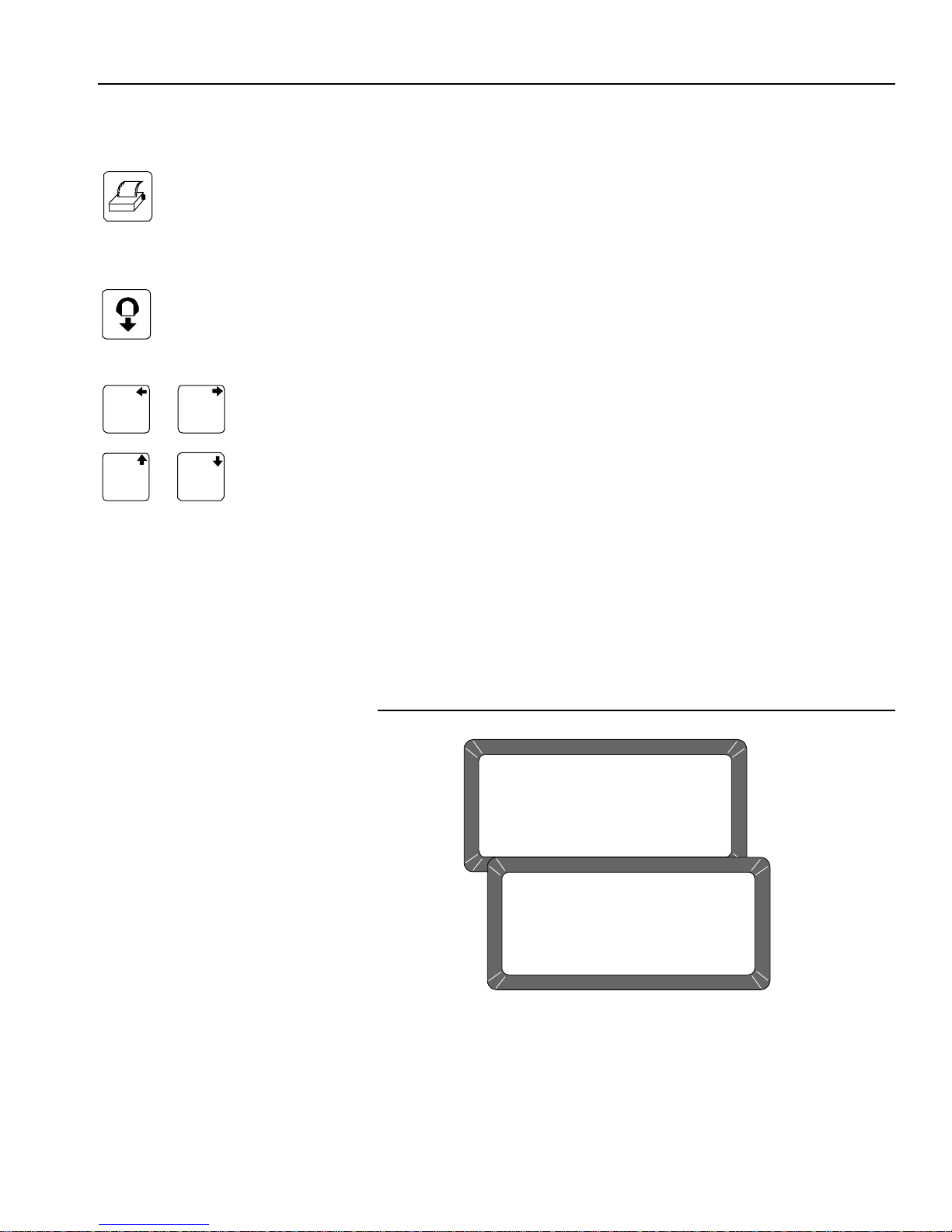
Print Key
PRINTER
An optional printer connected to the instrument can print test data results.
The printout can include:
• Facility name and address
• Current date and time
• Sample ID number
• Product name
• Grain calibration date
• Percent moisture
• Test Weight
• Grain temperature
• Unit serial number
• D1 through D4 values
Data can automatically print at the end of each measurement cycle or
manually initiated by pressing the Print key.
6 INTRODUCTION
GAC® 2100 Grain Analysis Computer (Blue, Gray, Agri Models)
11001-1688-201609

OPERATOR’S MANUAL
Shipping Brace Transport Handle
Operate
position
Transport
position
UNPACKING THE INSTRUMENT
DISENGAGE SHIPPING BRACE
The shipping brace must be moved to the operate position before
applying power . Sinc e the gr ain test c ell cycle s through an unload
sequence during power up, damage may occur with the shipping
brace in the transport position.
The GAC 2100 is shipped with the grain test cell supported by an internal
shipping/transport brace. This brace supports the test cell whenever the unit
is transported. The position of the brace is controlled by a handle lo cated on
the rear panel behind the grain test cell (Figure 5). A small spool is placed
over the handle to prevent possible bumping and release of the handle
during shipment.
To Disengage Shipping Brace:
1. Remove spool and store with shipping materials.
2. Push the handle in to unlock position and rotate counterclockwise to
the locked operate position as indicated on th e ba ck panel.
– The movement of the brace is viewable through the front window of
the unit.
Figure 3
Disengaging Shipping Brace
GAC® 2100 Grain Analysis Computer (Blue, Gray, Agri Models)
11001-1688-201609
UNPACKING THE INSTRUMENT 7

OPERATOR’S MANUAL
37.5 cm
(14.75 in.)
40.6 cm (16.00 in.)
38.7 cm (15.25 in.)
Front View
Top View
Side View
GRAIN ANALYSIS COMPUTER
GAC 2100
Rotate the brace back into supporting position before moving or
shipping the unit. If the cell is not adequat ely supporte d operat ing
performance may be adversely affected due to cell bouncing.
Some effort is required to move the brace back into position. It
may be helpful to reach inside the drawer front and lift up on the
cell while attempting to lock the brace into the transport position.
Place the spool over the handle to prevent the accidental release
of the shipping brace.
INSTRUMENT PLACEMENT
Choose a clean environment that is protected from rapid changes in
ambient temperature. Avoid a hazardous (classified) location as defined in
Article 500 of the NFPA Handbook of the National Electrical Code.
Instrument should be placed in a dry environment/area free to
standing water or dampness to avoid electrical shock.
Figure 4
GAC 2100 Dimensions
8 UNPACKING THE INSTRUMENT
GAC® 2100 Grain Analysis Computer (Blue, Gray, Agri Models)
11001-1688-201609

OPERATOR’S MANUAL
Rubber
Foot Pads
4. After adjustment, retighten nut up against
bottom panel.
1. Use wrench to loosen the upper nut
and then adjust height.
2. Ensure bottom nut is locked down
against rubber foot pad.
3. Use a Phillips screwdriver in center
of pad to change height and to hold
the screw from turning while tightening nuts.
To Level the Instrument:
1. Use the self-contained level on the panel top to position the GAC2100
on a flat level or nearly level surface.
2. Adjust the four rubber foot pads to level and stabilize the unit
(Figure 5). To adjust the foot pad height, unlock the upper nut from the
bottom panel of the selected foot pad and adjust height as required.
– All four leveling foot pads should be set to the lowest level possible
with one pad fully seated against the bottom panel. This ensures
minimum height above the counter top.
– When moving the instrument to a different location, re-leve ling may
be required.
3. After adjusting, use a Phillips screwdriver in the center of the foot pad
to hold the screw from turning and tighten the upper nut against the
bottom panel of the unit.
4. Ensure the lower nut remains tight against the foot pad.
Figure 5
Leveling With Rubber Foot Pads
GAC® 2100 Grain Analysis Computer (Blue, Gray, Agri Models)
11001-1688-201609
UNPACKING THE INSTRUMENT 9

OPERATOR’S MANUAL
10 UNPACKING THE INSTRUMENT
GAC® 2100 Grain Analysis Computer (Blue, Gray, Agri Models)
11001-1688-201609

OPERATOR’S MANUAL
Verify Shipping
Brace Transport
Handle is in
Operate
position
Line
Cord
Connector
On/Off
Switch
Display
Contrast
Control
Fuse
Assembly
INSTALLATION
Before shipping, the GAC 2100 is inspected and tested for mechanical and
electrical defects. After unp acking, visually inspect for possible dam age that
may have occurred during transit. Save all packing materials until the
inspection is complete. If damage is found, immediately file a claim with the
carrier and notify your DICKEY-john representative.
CONNECTING AC POWER
1. Verify that the ON/OFF (I/O) switch is in the OFF (O) position and that
the shipping brace is in the OPERATE position.
2. Plug the line cord into the connector on the rear panel next to the ON/
OFF switch.
3. Plug the male end into an appropriate 3-wire (grounded) outlet.
The grounding pin on the line cord connects directly to the
GAC 2100 frame. When using an adapter with a grounding wire
ensure the grounding wire is connected properly to a good earth
ground to prevent a shock hazard.
Figure 6
Connecting Power
GAC® 2100 Grain Analysis Computer (Blue, Gray, Agri Models)
11001-1688-201609
INSTALLATION 11

OPERATOR’S MANUAL
Tab
Tab
SAMPLE DRAWER BYPASS
Normal use of the sample drawer can be bypassed by removing the drawer
bottom and cutting a hole into the work counter to allow the tested grain
samples to fall through to a larger container below. The size of the hole
must be at least equal to the drawer dimension and located directly be neath
the grain sample drawer.
To Remove Sample Drawer Bottom:
1. To remove the bottom of the grain sample drawer, carefully lift the two
plastic tabs at the front of the drawer (Figure 7).
2. Using a small screwdriver, gently pry up on each tab and slide the
bottom panel out the rear of the drawer.
Use care when prying on tabs to prevent breakage.
3. When finished, slide the grain drawer back into position. This prevents
grain from spilling onto the work surface in front of the unit.
– If replacing the drawer bottom later, slide the bottom toward the
drawer front until it latches under the two plastic tabs.
Figure 7
Removing Drawer Bottom
12 INSTALLATION
GAC® 2100 Grain Analysis Computer (Blue, Gray, Agri Models)
11001-1688-201609

OPERATOR’S MANUAL
7189
4
5
6
2
3
0
.
–
Keys 0, 1, 3, and 5
also function as
arrow keys to navigate
to certain screens.
NAVIGATION
DISPLAY SCREEN
The display screen is a graphics Liquid Crystal Display (LCD) and is
backlighted for low light level viewing.
ADJUST SCREEN CONTRAST
The Display Contrast Control is on the rear panel (Figure 6) immediately
above the COM1 and COM2 ports. The contrast control changes the
contrast between the displayed charact er s an d th e backg ro u nd . Adju st th e
control as necessary for a comfortable contrast level in varying light
conditions.
KEYBOARD LAYOUT
All operator controls, except the Power ON/OFF switch and Contrast
control, are located on the front panel. These two are on the rear panel.
The sealed membrane keyboard contains 20 pressure-sensitive keys
requiring light finger pressure to actuate each key. Valid key closures result
in short tone bursts while invalid keystrokes generate longer tone bursts.
The function of each key or key group is defined as follows and illustrated in
(Figure 8).
GAC® 2100 Grain Analysis Computer (Blue, Gray, Agri Models)
11001-1688-201609
Numbers (0 through 9), Decimal point (.) and Minus (–) keys
All numeric keys perform dual functions, making menu selections, and
entering numeric values. The four numeric keys with small arrows ha ve the
additional function of screen navigation. When making a numeric entry, a
prompt on the display identifies the value entered and a cursor shows the
destination of each entry. The minus (-) sign is accepted at any point in the
entry and displays at the front of the entered str ing .
Figure 8
Keyboard Layout
Each entry immediately displays as the cursor moves to the right in
preparation for the next entry. Only the first entry of the decimal point is
acknowledged.
NAVIGATION 13

OPERATOR’S MANUAL
SELECT GRAIN
1: CORN 5: SOYBEANS
2: CORN HI MOIST 6: FESCUE
3: WHEAT HRW 7: BARLEY
4: OATS 8: RYE
PAGE 1 OF 8 <more>
Indicates
Additional Page
Indicates Number
of Pages
ALARM
An audible alarm is enabled for 0.5 seconds at the end of each grain
analysis or for an error condition. A shorter beep of 0.1 se conds soun ds fo r
each valid key stroke.
KEY FUNCTIONS
BACKSPACE KEY
Moves the cursor to the left to delete the last keystroke or to clear an entire
entry field.
NEXT PAGE KEY
Advances to the next page when the <more> prompt appears in the lower
right corner of the display. The Next Page key sequences the display
forward to additional pages of information. Th e total p age num ber and p age
count appear in the lower left corner of screen (i.e. PAGE 2 OF 8).
Figure 9
Typical Screen Indicating More Pages
14 NAVIGATION
PREVIOUS PAGE KEY
Sequences backward through previously displayed pages. Neither the
Previous Page or Next Page keys roll-over the pages to the beginning or
end.
ENTER KEY
Accepts the character string after an entry is complete.
LOAD KEY
Initiates a grain cell loading sequence to begin a test cycle.
HELP KEY
Provides context-sensitive help screens on the display. If the <more>
message appears at the lower right of the screen, additional pages are
accessible with the Next Page key. T o use th e HELP INDEX when in a Help
screen, select the 0 key and select the desired topic. To resume normal
operation, select the Help key a second time.
GAC® 2100 Grain Analysis Computer (Blue, Gray, Agri Models)
11001-1688-201609
OPERATOR’S MANUAL
1
3
&
5
0
&
MAIN MENU
1: MEASURE MOISTURE 3: CALIBRATION MENU
2: SELECT GRAIN 4: SETUP MENU
5: TESTS MENU
SELECT ITEM NUMBER (NEXT PAGE: STATUS)
STATUS
CYCLE COUNTER: 435
THIS COUNTER INCREMENTS AFTER EACH
SAMPLE MEASUREMENT OR DATA COLLECTION
SEQUENCE IS SUCCESSFULLY COMPLETED
PRINT KEY
Initiates a printout of current information on the screen (e.g., grain moisture
analysis, calibrations data, etc.). If the automatic printout o ption is selected ,
the Print key initiates duplicate copies. Help information does not print.
COM SETUP options allows the Print key to transmit to either the printer
port or the communications/modem port. For example, the system may be
configured to automatically print results through the printer port while the
Print key transfers results to the computer port.
UNLOAD KEY
Dumps the contents from the test cell after a grain test.
LEFT AND RIGHT KEYS
Moves the cursor horizontally during alpha entries and certain functions
during the SETUP mode.
UP AND DOWN KEYS
Moves the cursor vertically during alpha entries and certain functions in the
SETUP mode.
MENU SCREENS
The Main menu displays once the start-up checks are successfully
completed. The Main menu is the “home” screen that all other screens are
accessed. The Main menu displays five major selections or categories.
A number appears next to each Main menu selection. Select the desired
number to access the appropriate menu. Refer to (Figure 11) for a general
configuration of the Menu Tree layout.
Figure 10
Main Menu Selections
GAC® 2100 Grain Analysis Computer (Blue, Gray, Agri Models)
11001-1688-201609
NAVIGATION 15

OPERATOR’S MANUAL
<MORE>
<MORE>
<MORE>
<MORE>
<MORE>
<MORE>
<MORE>
SETUP MENU
MAIN MENU
1: MEASURE MOISTURE
2: SELECT GRAIN
SELECT ITEM NUMBER
(NEXT PAGE: STATUS)
3: CALIBRATION MENU
4: SETUP MENU
5: TESTS MENU
FILL SAMPLE HOPPER, ENTER ID NO. THEN
SETUP MENU
1: CLEAR COUNTER
2: ID OPTIONS
3: OUTPUT OPTIONS
4: EDIT ACCESS CODE
SELECT ITEM NUMBER
5: DATE/TIME MENU
6: LABELS MENU
7: COM MENU
8: SERVICE MENU
TESTS MENU
1: non-active
2: COM1
3: COM2 TRANSMIT
4: non-active
SELECT ITEM NUMBER
(NEXT PAGE: STATUS)
5: DISPLAY
6: DIAGNOSTIC MODE
7: TEST NETWORK MODE
8: PARAMETERS MENU
CALIBRATION MENU
1: VIEW CALIBRATION
2: ENTER/CHANGE CALIBRATION
3: PRINT CALIBRATION LIST
4: OBTAIN CALIBRATION DATA
5: PRINT AUDIT MEMORY DATA
SELECT ITEM NUMBER
(NEXT PAGE: STATUS)
<MORE>
PRESS LOAD TO BEGIN
CORN 91051
ID: 2
PAGE 8 OF 8
PAGE 7 OF 8
PAGE 6 OF 8
PAGE 5 OF 8
PAGE 4 OF 8
PAGE 3 OF 8
PAGE 2 OF 8
PAGE 1 OF 8
SELECT GRAIN
1: CORN
2: CORN HI MOIST
3: AMARANTH
4: BARLEY
5: SOYBEANS
4: DURUM
5: FESCUE
8: MILLET
GAC 2100 Blue
SELECT GRAIN
1: CORN
2: CORN HI MOIST
3. SOYBEANS
4: SORGHUM
5: WHEAT HRW
6: WHEAT HRS
7: WHEAT SRW
8: OATS
GAC 2100 AGRI
<MORE>
PAGE 2 OF 2
PAGE 1 OF 2
SELECT GRAIN
1: CORN
2: CORN HI MOIST
3: SOYBEANS
4: SORGHUM
5: WHEAT HRW
6. WHEAT HRS
7. WHEAT SRW
8: OATS
GAC 2100 Gray
Calibration Menu on the AGRI and Gray
instruments do not have
5. Print Audit Memory Data.
Figure 11
Menu Tree
16 NAVIGATION
GAC® 2100 Grain Analysis Computer (Blue, Gray, Agri Models)
11001-1688-201609

OPERATOR’S MANUAL
1: *ENGLISH US
2: NEDERLANDS
3: FRENCH
4: DEUTSCH
5: ITALIANO
6: PORTUGUES
7: ESPANOL
8: ENGLISH
PLEASE WAIT
PERFORMING STARTUP TESTS
GAC2100 REV: 0798121009
LANG REV: 0798121009
Language Software
Number
Instrument
Software
Number
STARTUP PROCEDURE
Each time the GAC 2100 is powered on, the instrument performs a series of
self checks to determine the status of the following:
• Load/strike-off mechanism
• Unload function
• Empty test cell weight
• Conductance/capacitance measurement circuitry
Self-checks begin when the hopper doors open, the strike-off arm swings
across the cell and back again, and the cell dumps. When the cycle ends
(about 15 seconds), the Main Menu displays.
Before starting the following procedures, ensure the ON/OFF (I/O)
switch is in the OFF (O) position and that the shipping brace is in
the OPERATE position. These are both located on the rear of the
unit.
1. Turn the power switch ON. Initially, a language screen appears
showing eight choices (Figure 12). Two English selections are
available: English US and English.
– English US invokes parameters to display test weight for
NTEP-certified calibrations used in the United St ates and allows the
option of displaying test weight on the Analysis screen.
– English is for non-NTEP users that do not require test weight
parameters.
Figure 12
Start Up Screens
GAC® 2100 Grain Analysis Computer (Blue, Gray, Agri Models)
11001-1688-201609
STARTUP PROCEDURE 17

OPERATOR’S MANUAL
2. Select a language by pressing the respective number on the keypad
next to the desired language.
– This screen only remains available for approximately 8 seconds.
– Once selected, an asterisk appears and remains in front of the
selection until changed again during another startup cycle.
3. Wait for the remaining portion of the cycle to finish. A second screen
displays PLEASE WAIT while the unit is performing self checks. The
bottom two lines of this screen display the software revision numbers
(Figure 12).
4. After the Main Menu displays proceed with general operation.
TEST SAMPLES (QUICK START)
Performing a grain sample analysis consists of six basic steps:
1. Select a grain for testing through keyboard entries.
2. Pour grain sample into the hopper (top of the unit) and enter a sample
ID number (optional).
3. Press the Load key. The sample automatically loads (drops) the grain
into the test cell and a strike-off arm levels and removes the excess.
4. Wait briefly for the test results to process. The moisture reading and
grain temperature display.
5. Print a hard copy of the test results.
– With an optional printer connected, the date and time with sample
identification number and all test information prints.
– By selecting the Print key, additional copies can be printed.
6. Press the Unload key to empty the test cell contents.
– The test cell rotates 180° (inverts) to dump the grain into a sample
drawer or into a larger container below the counter top.
– After the cell returns to the upright position, the instrument is ready
for the next test sample.
18 STARTUP PROCEDURE
GAC® 2100 Grain Analysis Computer (Blue, Gray, Agri Models)
11001-1688-201609

OPERATOR’S MANUAL
MAIN MENU
1: MEASURE MOISTURE 3: CALIBRATION MENU
2: SELECT GRAIN 4: SETUP MENU
5: TESTS MENU
SELECT ITEM NUMBER (NEXT PAGE: STATUS)
SELECT GRAIN
1: CORN 5: SOYBEANS
2: CORN HI MOIST 6: MILO
3: WHEAT HRW 7: BARLEY
4: AMARANTH 8: OATS
PAGE 1 OF 8 <more>
PLEASE WAIT
PERFORMING SELF-CHECKS
WHEAT HRW
ID: 14
960918
Sample ID Number
Selected Grain Type for Testing
MEASURE MOISTURE
The Main Menu appears immediately after all startup checks have
successfully concluded. The Main Menu displays five major selections for
categories.
To Measure Moisture:
1. Choose MEASURE MOISTURE (1 Key) from the Main menu to
display the Select Grain menu.
Figure 13
Moisture Testing Preparation
Next Page Key
Previous Page Key
GAC® 2100 Grain Analysis Computer (Blue, Gray, Agri Models)
11001-1688-201609
2. Locate the grain type for testing and select the corresponding number
to the left.
– After selecting a grain, the unit cycles through self-check tests to
ensure the program memory and calibrations are valid.
– Subsequent moisture measurements default to the previously
selected grain.
– For models with multiple pages on grains, select the Next Page
key.
3. If a different grain is desired, press the Previous Page key to return to
the Main menu.
4. Select the option SELECT GRAIN (2 key) and choose a new grain
(refer to GRAIN SELECTION for additional information).
5. Enter a sample ID number. This number identifies the sample tested
on the paper printout. If the ENTER REQUIRED FOR ID is turned ON
(refer to CHOOSING ID OPTIONS in the ESTABLISHING
P ARAMETERS section), the Enter Sample ID screen displays and an
ID number is required. Other ID numbering options bypass this screen.
Details on how to use ID numbers are described later in this section.
MEASURE MOISTURE 19

OPERATOR’S MANUAL
ENTER SAMPLE ID
WHEAT HRW
ID:
960918
PRESS LOAD TO BEGIN
WHEAT HRW
ID:AD38
960918
FILL SAMPLE HOPPER AND
6. Use the Down Arrow key (0 key) to place the cursor next to the ID and
enter any number.
7. Press the Enter key.
Figure 14
Screen Sequence Using Enter Required For ID
Load Key
Enter Key
BASIC METHOD
After all calibration self-checks for the selected grain are complete
(approximately 10 seconds), the message FILL SAMPLE HOPPER,
ENTER ID NO. THEN…PRESS LOAD TO BEGIN displays (Figure 15).
To Measure Moisture:
1. Pour grain into the sample hopper. Fill the hopper until the grain is at
least 1.25 cm (1/2 inch) above the separation line between the hopper
top and hopper compartment (heap gr ain slightly). The exa ct volume is
unimportant, except enough grain must be present to overfill the cell
(approx 0.5 liter or 2 cups). Excess grain spills over the cell top and
falls into the grain drawer below.
2. If an ID number is not entered, enter a number or skip to step 3.
3. Press the Load key to begin the test cycle.
4. GAC 2100 Blue- If factors (a type of label) are enabled, a screen
displays the message ENTER RESULTS FOR THE FOLLOWING.
– Disregard this screen by entering a number and selecting the Enter
key. Refer to FACTORS for additional information.
5. Press the Load key, the hopper do ors open and drop the grain into th e
test cell. The cell fills and the striker arm swings across the top to
remove excess grain.
20 MEASURE MOISTURE
Do not insert fingers or other foreign objects into the opened
hopper doors.
6. Wait for the moisture test to complete (Figure 15). A screen displays
the message MEASURING - PLEASE WAIT.
GAC® 2100 Grain Analysis Computer (Blue, Gray, Agri Models)
11001-1688-201609

OPERATOR’S MANUAL
PLEASE WAIT
MEASURING
WHEAT HRW
960918
ID: AD38
PRESS LOAD TO BEGIN
FILL SAMPLE HOPPER, ENTER ID NO. THEN
WHEAT HRW
ID:AD1234
960918
MOISTURE
13.4%
WHEAT HRW
TEMP: 30 C
ID: AD38 <more>
960918
Press
the
Load Key
PLEASE WAIT
PERFORMING SELF CHECKS
WHEAT HRW
960918
Press
the
Dump Key
Figure 15
Basic Moisture Measuring Cycle
7. The grain name, moisture, sample ID and grain calibration issue date
Next Page Key
8. The option <more> displays on the lower right corner of the screen.
9. Press the Next Page key to view additional pages. The D1 through D4
10. Blue model-If the <more> prompt continues to display, press the Next
Enter Key
Unload Key
GAC® 2100 Grain Analysis Computer (Blue, Gray, Agri Models)
11001-1688-201609
11. When the measurement is complete, select the Unload key. The test
12. Start a new moisture measurement for the same grain type. The
appears on the display along with the sample temperature and test
weight, if enabled.
values display along with the present date (lower left corner) and time
(lower right corner).
Page key again.
– This page is only available if FACTORS are used. FACTORS are a
type of label that allows entry of data for additional information on
the paper printout. Up to four user-defined factors (or labels) may
display and print as specified on the Setup menu. If this screen
displays, enter numbers as desired and select the Enter key. If no
factor names are specified, the screen will not display.
cell will invert dumping the grain and returning to the upright position.
GAC 2100 remembers the grain type until it is changed or power is
turned OFF. The Select Grain menu does not appear again until it is
selected.
MEASURE MOISTURE 21

OPERATOR’S MANUAL
ABCDEFGHIJKLMNOPQRSTUVQXYZ _ #$%&'( ) *,-.+
ÇOZÄ CÉLLS ÖÜ TLANZECAAES ADD Ë NIITUO ß ONSRUU
Y§R S1 S2 S3 S4 S5 S6 S7 S8 S9 S10
TEXT: -
“
“
´´´´´´´´´´´
ˆˆˆ°
~
±
1
3
&
5
0
&
Next Page Key
Left and Right Arrow Keys
GRAIN SAMPLE ID NUMBERS
Three sample ID options may be selected to number grain samples:
1. Automatic number sequencing (e.g., 1, 2, 3...)
2. Manual entry (numbers may be manually entered or skipped)
3. ENTER REQUIRED FOR ID (produces the Enter Sample ID screen)
which prompts a required entry before proceedin g. The ID field may be
either numeric or alphanumeric. If numeric only, the digits 0-9, the
decimal point, and the minus sign are entered with the keyboard. Other
characters are entered from an alpha screen.
ENTER NUMBERS AND ALPHA CHARACTERS
Entering alpha characters (letters) into certain screens, such as an ENTER
SAMPLE ID number, is accomplished through a special alpha screen.
To Access the Alpha Screen:
1. From the Enter Sample ID screen, press the Next Page key. The Next
Page key only functions if an alpha entry is possible.
To View and/or Use the Alpha Screen:
1. Prepare for a moisture test. When the PRESS LOAD TO BEGIN
message appears, stop and observe the screen. The ID field on the
lower left corner below the grain type appears and a small cursor will
blink. If necessary, use the Down Arrow key to position the cursor
next to the ID field (ID: _ ). Numbers are entere d dir ec tly fro m the
keypad and completed by selecting the Enter key.
2. To ente r letters, select the Next Pa ge key to ac cess the Alpha scr een.
The Alpha screen displays the alphabet, special characters, and a
string of S numbers (S1…S10). On the lower left corner, the word
TEXT displays (Figure 16).
Up and Down Arrow Keys
Enter Key
Backspace Key
22 MEASURE MOISTURE
Figure 16
Alpha Screen
3. Move the vertical pointer (center of screen) to the first letter. The small
vertical pointer identifies the selected character. The pointer is moved
around the screen by using the four arrow keys (Left/Right and Up/
Down).
4. After selecting a letter, press the Enter key. The letter appears next to
the word TEXT: on the lower corner. Repeat the process until the
GAC® 2100 Grain Analysis Computer (Blue, Gray, Agri Models)
11001-1688-201609

OPERATOR’S MANUAL
Previous Page Key
Backspace Key
phrase is complete. If an error is made, select the Backspace key and
re-enter the corrected character.
5. After completing the text string, select the Previous Page key . The text
string becomes part of the ID field on the Press Load To Begin
screen. Additional numbers can be inserted after the text string as
before. Deleting is accomplished by entering the alpha screen again
and using the Backspace key to delete letters.
– GAC 2100 Blue-Using the S1 through S10 character strings is
described in Instrument Setup. Character strings are predete rmined
phrases to insert into an alpha text line when needed (i.e.
BROWN).
ID OPTIONS
ID numbers typically identify grain samples. The numbers can be a simple
number (e.g., 1, 2, 3, etc.), a combination of letters and numbers (i.e.
operator’s initials plus sample number) or the customer’s name (i.e.
BROWN). The ID field can contain up to 16 alpha numeric characters.
The ID option is selected through the Setup menu, ID OPTIONS (refer to
Instrument Setup). ID numbers are added to each tested sample using one
of three methods:
1. Inserted Manually - Any ID field, including none at all, are assigned to
grain samples before each test. This flexibility allows the creation of
individualized numbering schemes.
2. Automatic Sequencing - Numbers can be sequentially assigned
automatically to each moisture test. For example, 1, 2, 3, etc. or
specific letters (i.e. initials) can be placed in front of the numbers (i.e.
JW12). Only the numbers at the end of the field change automatically.
3. Entry Required For ID - An ID field is required before each moisture
test can proceed. This method ensures each sample is properly
identified, typically for printer output. A screen displays before the
moisture test requests the user to ENTER SAMPLE ID. Alpha
characters can be used if desired.
FACTORS (LABELS)
Blue Model
Factors are predetermined labels that appear at the beginning of each
moisture test similar to sample ID numbers. Up to four factors display and
print as specified in the calibration. For each FACTOR specified, an entry
must be made before initiating the moisture measurement. Entries (numeric
only) can be up to six digits long (Figure 17). FACTORS are established on
the Setup menu (refer to Instrument Setup).
GAC® 2100 Grain Analysis Computer (Blue, Gray, Agri Models)
11001-1688-201609
MEASURE MOISTURE 23

OPERATOR’S MANUAL
CUSTOMER ID 54
VEHICLE NUMBER 4
CODE 382
LOAD WEIGHT 19535
WHEAT HRW
ID: AB1234
ENTER RESULTS FOR THE FOLLOWING:
960518
D1: nnnn
D2: nnnn
D3: nnnn
D4: nnnn
TEST WEIGHT OFFSET: +0.4 LB/BU
DATE: 05/18/16
ID: 12
TIME: 16:42:20
Blue model
only
Next Page Key
Figure 17
Example of Factors
NEXT PAGE VIEW
After the grain analysis is complete and the moisture content displays,
<more> appears on the lower right corner of the screen indicating another
page is available.
Press the Next Page key to view the calculated values (D1, D2, D3 and D4)
determined from the grain measurement (Figure 18). These values are
relatively unimportant to the operator but are important to service
personnel. A general definition of each value is as follows:
D1 - Conductance measurement to indicate grain surface moisture.
D2 - Capacitance measurement to indicate inte rnal grain moisture.
D3 - Weight measurement to indicate grain weight.
D4 - Temperature to indicate grain temperature.
Blue model-
Below the D calculations, the TEST WEIGHT OFFSET (as applicable)
appears. This value is programmed on the Setup menu (refer to Instrume nt
Setup). The current date, time, and sample ID also display.
Figure 18
Next Page Typical Calculated D-Values
24 MEASURE MOISTURE
GAC® 2100 Grain Analysis Computer (Blue, Gray, Agri Models)
11001-1688-201609

OPERATOR’S MANUAL
GRAIN SELECTION
The second item on the Main menu is the Select Grain menu to select
specific grain types for testing. The Select Grain menu automatically
displays for the first moisture test each time power is applied. It may also be
selected at any time to test different grain types. After the first test, the
Select Grain menu must be selected manually.
GAC 2100 Blue-One exception is through the use of QUICK KEYS.
However, these are limited to three grai n choices, usually the most common
grains. The use of QUICK KEYS allows a programmed grain to be selected
prior to loading the grain into the test cell (refer to ANALYZING GRAIN).
SELECT GRAIN MENU
Grain Calibration Storage
• GAC 2100 Blue-Stores up to 64 unique grain calibrations. The first 40
are restricted and can only be changed by authorized personnel. The
remaining 24 are less secure and can be changed using the access
code.
• GAC 2100 AGRI-Stores up to 8 different grain calibrations.
• GAC 2100 Gray-Stores up to 16 different grain calibrations.
To Select a Grain for Testing:
Next Page Key
Previous Page Key
1. Choose the Select Grain menu from the Main menu by selecting the 2
key.
– Blue and gray models - The first page of the Select Grain menu
displays the first eight grain calibrations available. The prompts on
each lower corner of the display indicate additional pages are
available (Figure 19).
2. Blue and Gray models - Press the Next Page key to advance to the
next page. The next eight grain calibrations will display. The Next
Page key allows access to all available eight pages. When the last
page displays, the <more> prompt no longer remains visible on the
screen.
– Press the Previous Page key to move backward. The Previous
Page key is the counterpart of the Next Page key.
GAC® 2100 Grain Analysis Computer (Blue, Gray, Agri Models)
11001-1688-201609
GRAIN SELECTION 25

OPERATOR’S MANUAL
PAGE 8 OF 8
PAGE 7 OF 8 <more>
PAGE 6 OF 8 <more>
PAGE 5 OF 8 <more>
PAGE 4 OF 8 <more>
PAGE 3 OF 8 <more>
PAGE 2 OF 8 <more>
SELECT GRAIN
1: CORN 5: SOYBEANS
2: CORN HI MOIST 6: MILO
3: WHEAT HRW 7: BARLEY
4: AMARANTH 8: OATS
PAGE 1 OF 8 <more>
SELECT GRAIN
1: CORN 5: WHEAT HRW
2: CORN HI MOIST 6: WHEAT HRS
3: SOYBEANS
4. SORGHUM
7: WHEAT SRW
8: OATS
SELECT GRAIN
1: CORN
2: CORN HI MOIST
3: SOYBEANS
4: SORGHUM
5: WHEAT HRW
4: WHEAT HRS
5: WHEAT SRW
8: OATS
PAGE 1 OF 2 <MORE>
1: BARLEY SIX ROWED
2: BARLEY TWO ROWED
3: WHEAT DURUM
4: SUNFLOWER OIL
5: MILLET
4: RAPE SEED
5: RYE
8: SAFFLOWER
PAGE 2 OF 2
Blue AGRI
Gray
Figure 19
Select Grain Menus
Load Key
3. Press the number key corresponding to the desired grain. After
selecting the grain, the GAC 2100 automatically enters the MEASURE
MOISTURE mode and retains the grain selection until a new grain is
selected again or the power is turned OFF.
QUICK KEYS
Blue Model
QUICK KEYS makes changing between frequently-used grains easier
during moisture measurements bypassing the Select Grain menu. Up to
three frequently used grains can be programmed for keyboard keys 1, 2,
and 3. The desired key (grain) changes the grain to be tested whenever the
1, 2, or 3 key is pressed on the Press Load to Begin screen.
26 GRAIN SELECTION
GAC® 2100 Grain Analysis Computer (Blue, Gray, Agri Models)
11001-1688-201609

OPERATOR’S MANUAL
CALIBRATION MENU
1: VIEW CALIBRATION
2: ENTER/CHANGE CALIBRATION
3: PRINT CALIBRATION LIST
4: OBTAIN CALIBRATION DATA
5: PRINT AUDIT MEMORY DATA
SELECT ITEM NUMBER (NEXT PAGE: STATUS)
STATUS
CYCLE COUNTER: 435
THIS COUNTER INCREMENTS AFTER EACH
SAMPLE MEASUREMENT OR DATA COLLECTION
SEQUENCE IS SUCCESSFULLY COMPLETED
View and print
selected grain
calibrations only.
Enter new or
edit existing
grain calibrations.
Print a list of
grain calibrations.
Obtain data to
determine
calibration constants
for a specic grain.
Print and/or
clear Audit
trail information
(Blue model)
Represents the total count
of samples processed since
the counter was last reset.
CALIBRATE PROCEDURES
The Calibration menu allows authorized personnel to:
• view calibration constants of selected grains
• enter new or change existing calibrations
• print the entire list of stored grain calibrations
• obtain calibration data necessary to generate new calibrations
• print audit memory data (Blue model)
Choose a function by selecting the number key corresponding to the
desired function (Figure 20).
Figure 20
Calibration Menu With Status Page
Next Page Key
Print Key
GAC® 2100 Grain Analysis Computer (Blue, Gray, Agri Models)
11001-1688-201609
VIEW CALIBRATION DATA (1 KEY)
The View Calibration menu allows for viewing and printing of a selected
grain calibration (Figure 21). Editing cannot be performed in this function.
To View Grain Calibrations:
1. From the Calibration menu, choose View Calibration by selecting the
1 key.
2. Choose a grain calibration to view from the grain list pages and then
select the corresponding number key.
–Use the Next Page key to view additional pages, if applicable.
3. The View Calibration screen displays the grain name, moisture range,
calibration issue date, and the nine calibration K values.
4. If a printer is connected, FACTORS (Blue model) are defined and
AUTO RANGE is specified in the calibration, this information also
prints. The lower right corner of the View Calibration screen indicates
<more> meaning another page is available.
5. Blue model-Press the Next Page key to display the Factors screen.
The Factors screen displays the grain name and up to four defined
factors. If the grain does not have defined factors, the labels are empty.
The <more> prompt also displays on this page.
CALIBRATE PROCEDURES 27

OPERATOR’S MANUAL
CALIBRATION MENU
1: VIEW CALIBRATION
2: ENTER/CHANGE CALIBRATION
3: PRINT CALIBRATION LIST
4: OBTAIN CALIBRATION DATA
5: PRINT AUDIT MEMORY DATA
SELECT ITEM NUMBER (NEXT PAGE: STATUS)
SELECT GRAIN TO VIEW
1: CORN 5: SOYBEANS
2: CORN HI MOIST 6: MILO
3: WHEAT HRW 7: BARLEY
4: AMARANTH 8: OATS
PAGE 1 OF 8 <more>
VIEW CALIBRATION
GRAIN: WHEAT HRW RANGE: 06 -20%
ISSUE: 960701
K1: 0433 K4: 2821 K7: 2006
K2: 3577 K5: 2500 K8: 0564
K3: 1368 K6: 2577 K9: 1044
<more>
VIEW CALIBRATION
GRAIN: WHEAT HRW
FACTOR 1: VEHICLE NUMBER
FACTOR 2:
FACTOR 3:
FACTOR 4:
<more>
VIEW CALIBRATION
AUTO RANGE FOR: WHEAT HRW
IF ABOVE MAX MOIST TRY: WHEAT HI MOIST
IF BELOW MIN MOIST TRY: WHEAT LO MOIST
Blue model
Next Page Key
6. Press the Next Page key to view the Auto Range screen. The Auto
Range screen displays grain name and calibrations automatically used
to extend the moisture range if the normal maximum and minimum
limits are exceeded. Separate grain calibrations or grains may be
referenced for each limit.
Figure 21
View Calibration Menu Showing Wheat HRW
28 CALIBRATE PROCEDURE S
ENTER/CHANGE CALIBRATION VALUES (2 KEY)
Blue model-This function enters or changes grain calibrations. Grains 1
through 40 are restricted to authorized personnel only. Grains 41 through 64
are considered “unofficial calibrations” and can be accessed by using the
Access Code. Changing calibrations is also possible through proper linking
with a computer (refer to the computer manual). The same security code
restrictions exist. After gaining access, changes to calibrations can be
accomplished (Figure 22).
GAC® 2100 Grain Analysis Computer (Blue, Gray, Agri Models)
11001-1688-201609

OPERATOR’S MANUAL
Next Page Key
Previous Page Key
Enter Key
To Enter/Change Calibration Values:
1. From the Calibration menu, press the 2 key to access Enter/Change
Calibration screen.
– (Blue model) PAGE 1 OF 8 of the Select Grain To Enter/Change
menu displays. The remaining pages are accessed by selecting the
Next Page and Previous Page keys.
2. Select the grain to be altered or locate an empty position to enter a
new calibration. Select the appropriate key corresponding to the listing.
A screen displays TO PROCEED, UNSEAL ACCESS PORT ON
REAR P ANEL and PRESS WHITE PUSHBUTTON.
– (Blue model) If the grain selected is on one of the first five grain
pages (5 x 8 = 40) changing the calibration is restricted to
authorized personnel only.
– (Blue model) If the grain selection is on pages 6, 7 or 8, these
calibrations can be altered after responding to the request to
ENTER ACCESS CODE.
– (Blue model) Enter the access code and select the Enter key to
proceed.
IMPORTANT: Unsealing the access port should only be performed by
an authorized user.
GAC® 2100 Grain Analysis Computer (Blue, Gray, Agri Models)
11001-1688-201609
CALIBRATE PROCEDURES 29

OPERATOR’S MANUAL
CALIBRATION MENU
1: VIEW CALIBRATION
2: ENTER/CHANGE CALIBRATION
3: PRINT CALIBRATION LIST
4: OBTAIN CALIBRATION DATA
5: PRINT AUDIT MEMORY DATA
SELECT ITEM NUMBER (NEXT PAGE: STATUS)
SELECT GRAIN TO ENTER/CHANGE
1: CORN 5: SOYBEANS
2: CORN HI MOIST 6: MILO
3: WHEAT HRW 7: BARLEY
4: AMARANTH 8: OATS
PAGE 1 OF 8 <more>
ENTER/CHANGE CALIBRATION
AUTO RANGE FOR: WHEAT HRW
IF ABOVE MAX MOIST TRY: WHEAT HI MOIST
IF BELOW MIN MOIST TRY: WHEAT LO MOIST
TO PROCEED
UNSEAL ACCESS PORT ON REAR PANEL
AND DEPRESS WHITE PUSHBUTTON
ENTER/CHANGE CALIBRATION
ENTER/CHANGE CALIBRATION
GRAIN: WHEAT HRW RANGE: 06 -20%
ISSUE: 960701
K1: 0433 K4: 2821 K7: 2006
K2: 3577 K5: 2500 K8: 0564
K3: 1368 K6: 2577 K9: 1044
Press to EDIT <more>
Press to SELECT GRAIN, 0 to DELETE
(Blue model)
Page #
varies based
on model
Figure 22
Changing Calibrations
Backspace Key
Next Page Key
NOTE: Selecting the Next Page key
instead of the Backspace key
(to change the large flashing
block to the cursor), advances
to the AUTO RANGE function.
30 CALIBRATE PROCEDURE S
3. If selecting an existing calibration, a large flashing block appears on
the grain selection.The screen displays the current K values for that
grain. The large flashing block signifies that alpha characters can be
entered from the alpha screen.
– Press the Backspace key, as prompted on the bottom of the
screen, causes the bottom prompt to disappear and the large
flashing block to change to a cursor (flashing line).
– When the cursor appears, the alpha screen may be accessed by
selecting the Next Page key. If numeric entries are desired, those
values are made directly with the number keys.
4. Use the alpha screen to enter a grain name (up to 16 characters).
– Select the Enter key after each character selection to place the
character on the text line.
– Press the Previous Page key to return to the Enter/Change
Calibration screen. Note that the new grain title is now in place.
5. Press the Enter key to accept the new grain title. The cursor advances
to the next position (Issue Date).
6. Enter the Calibration Issue Date (up to 8 characters) and select the
Enter key . The cursor returns to a flashing blo ck in the ISSUE position.
The block signifies the date may include alpha characters (i.e.
GAC® 2100 Grain Analysis Computer (Blue, Gray, Agri Models)
11001-1688-201609

OPERATOR’S MANUAL
Enter Key
Backspace Key
Print Key
15NOV98) but normally is entered as numbers in a format such as
YYMMDD (i.e. 981115).
– Pressing the Backspace key will cause the flashing block to
disappear allowing the Next Page key to be used for selecting the
alpha screen.
7. Press the Enter key to accept the date. The cursor appears as a line
(flashing) under the first digit of K1 (const ant). The flashing cursor
(line) signifies this entry accepts only numbers.
8. Enter the K1 constant. Notice when entering the first digit the
remaining spaces are blank. All four digits of the constant must be
entered when making a change. If more than four digits ar e enter ed, a
long beep indicates an illegal entry.
9. When finished, press the Enter key to accept the constant and to
advance to the next position. If the screen is accidentally advanced
before finishing, press the Enter key as many times as necessary to
cycle through all menu items.
10. Enter K2 through K9 constants in the same manner as K1.
11. Press the Enter key after entering each constant (4 digits).
12. Press the Print key to print the calibration . The pr esent screen values
print.
13. Press the Next Page key to enter the Auto Range calibration
selection. The Auto Range screen allows entry for grains using higher
or lower moisture levels than the current calibration. These values are
automatically selected if the grain moisture is outside the standard
setting.
14. Press the Backspace key and choose a grain calibration if the sample
moisture is above the upper limit. After selecting a grain, the display
will return to the Auto Range screen. Repeat this procedure again for
the lower limit grain calibration.
15. Press the 0 (zero) key to delete either auto range calibration.
16. Press the Previous Page key to return to the Grain Calibration
screen.
GAC® 2100 Grain Analysis Computer (Blue, Gray, Agri Models)
11001-1688-201609
PRINT CALIBRATION GRAIN LIST (3 KEY)
Grain calibrations stored in memory can be printed by selecting the Print
key (Figure 23).
To Print a Calibration List:
1. Press the 3 key from the Calibration menu. The Print Calibration
List screen appears.
2. Select the Print key. The list of all grain calibrations will print.
CALIBRATE PROCEDURES 31

OPERATOR’S MANUAL
CALIBRATION MENU
1: VIEW CALIBRATION
2: ENTER/CHANGE CALIBRATION
3: PRINT CALIBRATION LIST
4: OBTAIN CALIBRATION DATA
5: PRINT AUDIT MEMORY DATA
SELECT ITEM NUMBER (NEXT PAGE: STATUS)
PRINT CALIBRATION LIST
Press PRINT to LIST CALIBRATIONS
Blue model
Figure 23
Printing Calibration Lists
OBTAIN BASIC CALIBRATION DATA (4 KEY)
This mode allows the user to generate data for developing grain
calibrations. The samples used for calibration should span the desired
moisture range.
Next Page key
Enter Key
Load Key
IMPORTANT : To obtain good calibration data, the samples must be as
evenly distributed throughout the moisture range as
possible. The grain samples should extend at least 2%
past each end of the desired moisture range, should
contain no spoilage or condensation, and be free of
broken pieces or foreign matter. The GAC 2100 readings
obtained can be sent to DlCKEY-john to derive the
calibration constants for the new grain.
To Obtain Accurate Calibration Constants:
1. Turn the power switch ON and allow approximately thirty minutes to
warm up before taking sample readings.
2. Turn the printer ON.
3. Verify the instrument is set up and functioning properly.
4. From the Main menu, choose the Calibration menu by pressing the 3
key.
5. Press the 4 key and select OBTAIN CALIBRATION DATA.
6. Enter a sample identification number so the sample is properly
identified. Key in a sample ID number (use the Next Page key if an
alpha ID is desired).
7. Press the Enter key.
8. Pour the sample into the hopper and press the Load key.
9. After the measurement cycle is complete, the screen displays four D
values (Figure 24). If using a printer, a printout automatically results. If
a printer is not used, record the D-values and sam p le ID.
32 CALIBRATE PROCEDURE S
GAC® 2100 Grain Analysis Computer (Blue, Gray, Agri Models)
11001-1688-201609

OPERATOR’S MANUAL
CALIBRATION MENU
1: VIEW CALIBRATION
2: ENTER/CHANGE CALIBRATION
3: PRINT CALIBRATION LIST
4: OBTAIN CALIBRATION DATA
5: PRINT AUDIT MEMORY DATA
SELECT ITEM NUMBER (NEXT PAGE: STATUS)
PERFORMING SELF CHECKS
PLEASE WAIT
OBTAIN CALIBRATION DATA
ID:
ENTER SAMPLE ID
OBTAIN CALIBRATION DATA
ID: 22
FILL SAMPLE HOPPER AND
PRESS LOAD TO BEGIN
OBTAIN CALIBRATION DATA
ID: 22
MEASURING
PLEASE WAIT
OBTAIN CALIBRATION DATA
ID: 22
D1: 8
D2: 674
D3: 2467
D4: 272
OBTAIN CALIBRATION DATA
DATE: 09/15/13 TIME: 20:10:19
ID: 22
Blue model
Figure 24
Obtaining Calibration Data
NOTE: The facility name and location,
date/time, GAC 2100 serial
number and calibration data
print when the first sample is
run in this mode (Figure 25).
Unload Key
10. Write the grain type under the CALIBRATION DATA. Write the actual
moisture percentage of each sample (obtained by an accurate
approved means) next to STD. MOIST.
11. Run additional samples and record the actual moisture percentage for
each sample.
12. After runnin g each sam ple , pr es s the Unload key.
GAC® 2100 Grain Analysis Computer (Blue, Gray, Agri Models)
11001-1688-201609
CALIBRATE PROCEDURES 33

OPERATOR’S MANUAL
DICKEY-JOHN
CORP_GAC 2100
09/29/16 10:32:28
S/N: 1737-90909
CALIBRATION DATA
===============
ID: 1.1
STD. MOIST:
D1: 0
D2: 672
D3: 2412
D4: 233
===============
Figure 25
Calibration Data Printout
Print Key
PRINT AUDIT MEMORY DATA (5 KEY)
(Blue model)
The audit memory records data changes made to parameters affecting
moisture measurement or the display of the measurement data. The audit
memory stores the following types of data:
• Grain calibration settings
• Output option settings
• Date and time settings
• Moisture bias and slope adjustment settings
Memory contents can be printed at any time. Printing audit memory can be
initiated from either the unit or the computer site (Figure 27). For additional
information concerning printing from the computer, refer to the
Communications Software manual included with the Communication
software.
To Print the Audit Memory Contents:
1. From the Main menu, access the Calibration menu by selecting the 3
key.
– Access PRINT AUDIT MEMORY DATA by selecting the 5 key. A
screen appears displaying PRESS PRINT TO BEGIN.
2. Press the Print key to obtain a printout of the audit memory
(Figure 26). Multiple copies can be produced by selecting the Print key
again when the printer finishes. If only the header, current date, current
time, and GAC 2100 serial number print during this process, the audit
memory is empty.
34 CALIBRATE PROCEDURE S
GAC® 2100 Grain Analysis Computer (Blue, Gray, Agri Models)
11001-1688-201609

OPERATOR’S MANUAL
DICKEY-JOHN
40554
CURRENT DATE/TIME
29/09/16 10:32:28
S/N: 1716-40554
EVENT COUNTER: 1
DATE OF CHANGE:
09/29/16 MM/DD/YY
TIME OF CHANGE:
10.33.25 HH.MM.SS
LOG ON TIME:
00.00.00 HH.MM.SS
CHGCD:
000000
PID: TIME
10.34.00 HH.MM.SS
===============
CALIBRATION MENU
1: VIEW CALIBRATION
2: ENTER/CHANGE CALIBRATION
3: PRINT CALIBRATION LIST
4: OBTAIN CALIBRATION DATA
5: PRINT AUDIT MEMORY DATA
SELECT ITEM NUMBER (NEXT PAGE: STATUS)
PRINT AUDIT MEMORY DATA
Press PRINT to begin
Blue model
Figure 26
Audit Memory Data
Previous Page Key
Figure 27
Printing Audit Memory Data (Blue Model)
3. After printing , press the Previous Page key to return to the
Calibration menu.
GAC® 2100 Grain Analysis Computer (Blue, Gray, Agri Models)
11001-1688-201609
CALIBRATE PROCEDURES 35

OPERATOR’S MANUAL
PID: Denition of Terms
CB* Calibration
USRCD User Code
OO - D&OTW Output Option - Display & Output Test Wright
OO - D & OT Output Option - Display & Output Temperature
OO - DOOLR Output Option - Display & Out-Of-Limits Results
OO - OOOLR Output Option - Output Out- Of-Limits Results
OO - OROAE Output Option - Output Report Of All Errors
OO - MPR Output Option - Moisture Printout Resolution
OO - RP Output Option - Radix Point
OO - TF Output Option - Temperature Format
OO - WF Output Option - Weight Format
TIME Time
DATE Date
DATE FORMAT Date Format
Table 1: Audit Memory Parameter Identication (PID) Codes
AUDIT MEMORY FULL!
OPERATION CANNOT BE PERFORMED
Each event lists the following items:
1. Date of change
2. Time of change
3. Log on time
4. User code (Figure 26).
The user code prints asterisks to maintain user code security. The event (or
change) is identified with a PID (Parameter Identification), a colon and then
a code to indicate the specific type of change (refer to Table 1). The printout
begins with the most recent event and progresses in reverse order to the
oldest event.
MEMORY FULL
(Blue Model)
When the instrument reaches 1000 event s, a memory full message displays
and no additional events can be recorded until a udit memory is cleared. The
unit will not respond to keypad input and must be turned off and on to regain
control and to resume normal grain measurement routines. If any attempt is
made to modify an auditable parameter , the warning reap pears and must be
cleared again. This limitation persists until the memory is cleared.
Figure 28
Audit Memory Full Screen
36 CALIBRATE PROCEDURE S
GAC® 2100 Grain Analysis Computer (Blue, Gray, Agri Models)
11001-1688-201609

OPERATOR’S MANUAL
PRINTING AUDIT MEMORY COMPLETE
1: CLEAR AUDIT MEMORY
2: DO NOT CLEAR AUDIT MEMORY
TO PROCEED
Unseal Access Port on Rear Panel
and Depress White Push Button
Previous Page Key
After Printing Audit Memory:
1. Press the Previous Page key.
2. After printing, select (1 key) to clear audit memory or (2 key) to retain
audit memory.
Figure 29
Printing Complete Screen (Blue Model)
To Clear Audit Memory:
Clearing Audit Memory should only be performed by an authorized user.
1. Press the (1 key) Clear Audit Memory on the display.
2. Locate the access port door located on the back of the instrument and
remove seal, if necessary, from the door.
3. Remove screw to open access port door.
4. Press the white security button located on the bottom of the circuit
board to advance to the next screen.
5. When the white push button is pressed, audit memory is cleared and
the unit returns to the Calibration menu.
GAC® 2100 Grain Analysis Computer (Blue, Gray, Agri Models)
11001-1688-201609
CALIBRATE PROCEDURES 37

OPERATOR’S MANUAL
38 CALIBRATE PROCEDURE S
GAC® 2100 Grain Analysis Computer (Blue, Gray, Agri Models)
11001-1688-201609

OPERATOR’S MANUAL
MAIN MENU
1: MEASURE MOISTURE 3: CALIBRATION MENU
2: SELECT GRAIN 4: SETUP MENU
5: TESTS MENU
SELECT ITEM NUMBER (NEXT PAGE: STATUS)
SETUP MENU
1: CLEAR COUNTER
2: ID OPTIONS
3: OUTPUT OPTIONS
4: EDIT ACCESS CODE
SELECT ITEM NUMBER
<more>
5: DATE/TIME MENU
6: LABELS MENU
7: COM MENU
8: SERVICE MENU
SETUP MENU
1: QUICK KEYS MENU
2: TEST WEIGHT BIAS ADJUSTMENT
3: TEST WEIGHT SLOPE ADJUSTMENT
4: MOISTURE BIAS ADJUSTMENT
5: MOISTURE SLOPE ADJUSTMENT
SELECT ITEM NUMBER
(NEXT PAGE: STATUS)
Resets the accumulated
sample count since
last reset.
Sets Method
of identifying
grain samples.
Congures information
appearing on display
and printout.
Allows changing
the Access Code.
Sets the date, time,
and date format.
Allows for a Bias and
Slope oset value adjustment
to test weight and moisture
values to enhance agreements
Establishes output
parameters for
communications with
printer and computer.
Contains constants
aecting unit accuracy
(used by technical
personnel)
Label setup
for printout.
Blue model-Sets a key
for quick grain selection
when testing moisture
INSTRUMENT SETUP
The Setup menu establishes basic operating parameters for the unit.
These parameters include:
• Resetting the cycle counter
• ID options
• Output options
• Setting the access code
• Setting date and time
• Entering labels
• Configuring communication ports
From the Main menu, the Setup menu is accessed by selecting the 4 key.
From the Setup menu, eight sub-menus will appear. Most functions require
the access code before changes can occur . If the access code has not been
changed, the factory installed temporary code is set for 0 (zero).
Figure 30
Setup Menu Choices
Enter Key
GAC® 2100 Grain Analysis Computer (Blue, Gray, Agri Models)
11001-1688-201609
CLEAR CYCLE COUNTER (1 KEY)
The CYCLE COUNTER increments once each time a moisture
measurement or data collection sequence is successful. The screen
displays the total counts accumulated since the last reset.
To Reset the Cycle Counter:
1. From the Setup menu, press the 1 key (NOTE:). A screen displays
ENTER ACCESS CODE.
2. Enter the current personal access code (or 0) and press the Enter key .
Enter 0 if the code has not been changed from factory settings.
INSTRUMENT SETUP 39

OPERATOR’S MANUAL
SETUP MENU
1: CLEAR COUNTER
2: ID OPTIONS
3: OUTPUT OPTIONS
4: EDIT ACCESS CODE
SELECT ITEM NUMBER
<more>
5: DATE/TIME MENU
6: LABELS MENU
7: COM MENU
8: SERVICE MENU
CYCLE COUNTERS
ENTER ACCESS CODE: __
CYCLE COUNTER: 4358
THIS COUNTRER INCREMENTS AFTER EACH
SAMPLE MEASUREMENT OR DATA COLLECTION
SEQUENCE IS SUCCESSFULLY COMPLETED
PRESS TO CLEAR CYCLE COUNTER
3. Press the Enter key again to reset the number (count) to zero. The
counter returns to zero.
NOTE: The date, time, and cycle
counter values are
automatically sent to the COM1
and COM2 ports each time the
counter is cleared resulting in a
printout of the most recently
cleared counter contents. The
printout should be retained for
records. Com 2 Baud Rate is
115,200, 8 data bits, no parity,
and 1 stop bit.
Figure 31
Clearing The Cycle Counter
Enter Key
40 INSTRUMENT SETUP
ID OPTIONS (2 KEY)
ID OPTIONS determines how each moisture measurement sample is
identified on the output data. ID numbers appear in the lower left corner of
each test result screen. All sample ID numbers can contain up to 16
alphanumeric characters. Three methods of sample identification are
available for display:
• Automatic Sequential ID – Automatically increments once for each
measurement cycle, but resets each time the unit is turned OFF.
• Enter Required for ID – With each measurement, a screen displays
ENTER SAMPLE ID before the grain sample is measured. This option
ensures a grain sample identification number/label is assigned for
each test printout.
• Optional Entry ID – If both of the selections have been checked NO,
the ID number can be added to each measureme nt m an ua lly or not
at all. Manually added ID numbers do not require any specific format
or sequencing.
To Configure the ID Options:
1. From the Setup menu, select the 2 key to access the ID Options
screen (Figure 32). A screen displays ENTER ACCESS CODE.
2. Enter the access code (or 0) and select the Enter key. The ID Option
screen displays only two lines but allows three choices – the
AUTOMATIC SEQUENTIAL ID and ENTER REQUIRED FOR ID
functions cannot both be enabled (YES) at the same time.
GAC® 2100 Grain Analysis Computer (Blue, Gray, Agri Models)
11001-1688-201609

OPERATOR’S MANUAL
5
0
&
1
3
&
SETUP MENU
1: CLEAR COUNTER
2: ID OPTIONS
3: OUTPUT OPTIONS
4: EDIT ACCESS CODE
SELECT ITEM NUMBER
<more>
5: DATE/TIME MENU
6: LABELS MENU
7: COM MENU
8: SERVICE MENU
ID OPTIONS
ENTER ACCESS CODE: __
ID OPTIONS
AUTOMATIC SEQUENTIAL ID: YES
ENTER REQUIRED FOR ID : NO
TO SELECT,
TO CHANGE
Up/Down Arrow Keys
Left/Right Arrow Keys
3. Select the desired function. Use the Up/Down Arrow keys (0 and 5
keys) to select and the Left/Right Arrow keys (1 and 3 key) to set the
desired value. If both selections are set to NO, grain sample ID is
optional for each test.
Figure 32
Selecting ID Options
GAC® 2100 Grain Analysis Computer (Blue, Gray, Agri Models)
11001-1688-201609
CONFIGURE OUTPUT OPTIONS (3 KEY)
OUTPUT OPTIONS configure information appearing on the display/printer
for measured test results (Figure 34). These selections are typically made
once and not changed again, but may be altered as necessary. Selections
are available only to authorized personnel through either the User ID Code
from the computer site or as outlined below.
To Change the Output Options:
1. From the Setup menu, select OUTPUT OPTIONS (3 key). A screen
displays instructions on how to proceed.
Locating the Instrument Security Button:
2. Locate the access port door located on the back of the instrument and
remove seal, if necessary, from the door.
3. Remove screw to open access port door.
4. Press the white security button located on the bottom of the circuit
board to advance to the next screen.
INSTRUMENT SETUP 41

OPERATOR’S MANUAL
Security
Button
5
0
&
1
3
&
Up/Down Arrow Keys
Left/Right Arrow Keys
Figure 33
Security Button Location
5. Verify each option and set as necessary.Three pages must be verified
(Figure 34). Use the Up/Down Arrow keys (0 or 5) to select functions
and the Left/Right Arrow keys (1 or 3) to set each function to the
appropriate setting. Options include:
– DISPLAY AND OUTPUT TEST WEIGHT: Enables/disables (YES/
NO) approximate grain test weight to display and print.
– DISPLAY AND OUTPUT TEMPERATURE: Enables/disables
(YES/NO) grain temperature to display an d pr int .
– DISPLA Y OUT-OF-LIMITS RESULT: Error messages flash on the
display each time tested grain parameters exceed the normal range
of that particular grain. If enabled, three standard parameters
display – moisture, grain temperature, and approximate grain test
weight. Each measured parameter value appears next to its
respective legend on the display. The display out-of-limit options
selected below establish whether or not the enabled values ap pear
on the display . Eight sep arate settings are available for suppre ssing
the enabled grain parameters.
– OUTPUT OUT-OF-LIMITS RESULT: If enabled, three standard
parameters are printed – moisture, grain temperature, and
approximate grain test weight. Each measured parameter value
appears next to its respective legend on the printout. The output
out-of-limit options selected establish whether or not the enabled
values print. These choices are identical to the display out-of-limits
conditions above and are selected in a similar fashion.
SETTINGS:
1. YES - Enabled readings display for all out-of-limit conditions.
2. NO - Enabled readings do not display for any out-of-limit
condition.
3. M - Enabled readings display if moisture is out-of- limits but do
not display if either weight and/or temper at ur e is out-of-limits.
4. W - Enabled readings display if weight is out-of-limits but do
not display if either moisture and/or temperature is
out-of-limits.
5. T - Enabled readings display if temperature is out-of-limits but
42 INSTRUMENT SETUP
GAC® 2100 Grain Analysis Computer (Blue, Gray, Agri Models)
11001-1688-201609

OPERATOR’S MANUAL
do not display if either weight and/or moisture is out-of-limits.
6. MW- Enabled readings display if moisture and/or weight is
out-of-limits but do not display if temperature is out of limits.
This is the current approved setting for NTEP units.
7. MT -Enabled readings display if moisture and/or temperature
is out-of-limits but do not display if weight is out-of-limits.
8. WT - Enabled readings display if weight and/or temperature is
out-of-limits but do not display if moisture is out-of-limits.
– OUTPUT REPORT OF ALL ERRORS: Enables all internal
checked errors to print.
– MOISTURE PRINT RESOLUTION: Selects the resolution to either
one tenth (0.1) percent or one hundredth (0.01) percent for
moisture printout.
– RADIX POINT : Selects a decimal point ( . ) or comma ( , ) to display
and printout.
– TEMPERATURE FORMAT: Selects either degrees C (°C) or
degrees F (°F) to display and print for temperature.
– WEIGHT FORMAT: Selects either pounds per bushel (lb/bu) or
kilograms per hectoliter (kg/hl) to display and print.
GAC® 2100 Grain Analysis Computer (Blue, Gray, Agri Models)
11001-1688-201609
INSTRUMENT SETUP 43

OPERATOR’S MANUAL
OUTPUT OPTIONS
DISPLAY & OUTPUT TEST WEIGHT YES
DISPLAY & OUTPUT TEMPERATURE YES
DISPLAY OUT-OF-LIMITS RESULT YES
OUTPUT OUT-OF-LIMITS RESULT YES
SETUP MENU
1: CLEAR COUNTER
2: ID OPTIONS
3: OUTPUT OPTIONS
4: EDIT ACCESS CODE
SELECT ITEM NUMBER
<more>
5: DATE/TIME MENU
6: LABELS MENU
7: COM MENU
8: SERVICE MENU
OUTPUT OPTIONS
TO PROCEED
UNSEAL ACCESS PORT ON REAR PANEL
AND DEPRESS WHITE PUSHBUTTON
TO SELECT,
TO CHANGE
<more>
OUTPUT OPTIONS
OUTPUT REPORT OF ALL ERRORS YES
MOISTURE PRINTOUT RESOLUTION 0.1
RADIX POINT .
TEMPERATURE FORMAT F
TO SELECT,
TO CHANGE
<more>
OUTPUT OPTIONS
WEIGHT FORMAT : LB/BU
TO SELECT,
TO CHANGE
PRESS WHITE PUSHBUTTON
Figure 34
Setting Output Options
CHANGE THE ACCESS CODE (4 KEY)
The Access Code establishes a security level for nearly all Setup Menu
functions.
Blue Model: The Access code also allows modifying the unprotected grain
calibrations to the instrument. (refer to CALIBRATE PROCEDURES). A
higher security level is reserved for authorized personnel to make official
grain calibration changes and requires breaking the seal on the rear panel
of the unit and pressing the push button inside the access panel.
44 INSTRUMENT SETUP
GAC® 2100 Grain Analysis Computer (Blue, Gray, Agri Models)
11001-1688-201609

OPERATOR’S MANUAL
SETUP MENU
1: CLEAR COUNTER
2: ID OPTIONS
3: OUTPUT OPTIONS
4: EDIT ACCESS CODE
SELECT ITEM NUMBER
<more>
5: DATE/TIME MENU
6: LABELS MENU
7: COM MENU
8: SERVICE MENU
EDIT ACCESS CODE
ENTER ACCESS CODE: __
EDIT ACCESS CODE
ACCESS CODE ___ 10
Enter Key
Previous Page key
The access code is set to 0 when shipped from the factory. After selecting a
different code, record the new number and sto re for safe kee ping. DO NOT
lose the new code. Contact DICKEY-john or your local authorized service
center to recover the access code.
To Chang e th e Ac ce s s Co de :
1. From the Setup menu, select the EDIT ACCESS CODE (4 key). The
screen displays ENTER ACCESS CODE.
2. Enter the present code (or 0 if set at factory code) and press the Enter
key. The Edit Acce ss Code screen displays a blank (to be filled in).
The present access code appears to the right (Figure 35).
3. Enter the new access code. Choose any numeric code of up to
4-digits.
4. Enter the number and press the Enter key. The new nu m be r mu st be
used from this point forward to enter the access code level secured
screens.
5. Press Previous Page to exit.
Figure 35
Changing The Access Code
GAC® 2100 Grain Analysis Computer (Blue, Gray, Agri Models)
11001-1688-201609
INSTRUMENT SETUP 45
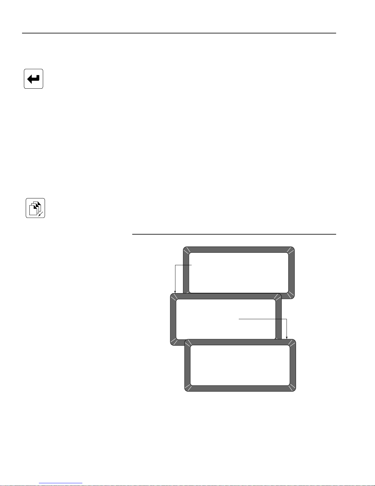
OPERATOR’S MANUAL
DATE/TIME MENU
1: SET TIME
2: SET DATE
3: SET DATE FORMAT
SELECT ITEM NUMBER
(NEXT PAGE: STATUS)
SET TIME
ENTER ACCESS CODE: __
SET TIME
CURRENT TIME IS 02 : 21 : 40
ENTER NEW TIME (HH. MM. SS) :
CHANGE DATE, TIME, AND DATE FORMAT (5
KEY)
Enter Key
Previous Page Key
This function establishes correct date and time for display and print out with
each grain moisture measurement.
To Set the Time:
1. From the Setup menu, select the Date/Time menu (5 key). Three
options are available; (1) SET TIME, (2) SET DATE and (3) SET DATE
FORMAT (Figure 36).
2. From the Date/Time menu, select SET TIME using the 1 key. The Set
Time screen appears and displays ENTER ACCESS CODE.
3. Enter the access code and select the Enter key. The time displays
based upon a 24-hour clock.
4. Change the time by entering new numbers from the keyboard. The
time format is in hours, minutes, seconds (HH.MM.SS). Each unit is
two digits and is separated by a decimal point.
– For example, to enter 3:32:59 P.M., enter 15.32.59. Use decimal
points to separate units. If accuracy is desired, set the time slightly
ahead and wait. At the exact time, press the Enter key to start the
clock.
5. Press Previous Page to exit.
Figure 36
Setting The Time
46 INSTRUMENT SETUP
GAC® 2100 Grain Analysis Computer (Blue, Gray, Agri Models)
11001-1688-201609

OPERATOR’S MANUAL
DATE/TIME MENU
1: SET TIME
2: SET DATE
3: SET DATE FORMAT
SELECT ITEM NUMBER
(NEXT PAGE: STATUS)
SET DATE
ENTER ACCESS CODE: __
SET DATE
CURRENT DATE IS 09 : 21 : 16
ENTER NEW DATE (MM. DD. YY) :
1
3
&
Enter Key
Previous Page Key
To Chang e the Da te :
1. From the Date/Time menu, select the SET DATE (2 key) menu
(Figure 37). The Set Date screen displays ENTER ACCESS CODE.
2. Enter the access code to gain and select the Enter key. Enter numbers
in the format shown at display bottom: month.day.year. Each date
component is two digits in length and separated by a decima l point (i.e.
to enter 9/15/16, enter 09.15.16). The number appears on the left end
of the bottom line.
3. Press the Enter key to accept the co rre ct ed da te.
4. Press the Previous Page key to return.
Figure 37
Setting The Date
Left/Right Arrow Keys
GAC® 2100 Grain Analysis Computer (Blue, Gray, Agri Models)
11001-1688-201609
To Change the Date Format:
1. From the Date/Time menu, select the SET DATE FORMAT (3 key)
menu (Figure 38). The screen displays ENTER ACCESS CODE.
2. Enter the access code and press the Enter key. The date format can
be configured in one of three formats:
– MM/DD/YY
– DD/MM/YY
– YY/MM/DD.
3. Press the Left or Right Arrow keys (1 or 3) to select one of the three
formats.
4. When finished, press the Left or Right Arrow keys to accept the
choice and return to the Date/Time menu.
5. Press the Previous Page key once more to return to the Setup menu.
INSTRUMENT SETUP 47

OPERATOR’S MANUAL
DATE/TIME MENU
1: SET TIME
2: SET DATE
3: SET DATE FORMAT
SELECT ITEM NUMBER
(NEXT PAGE: STATUS)
SET DATE FORMAT
ENTER ACCESS CODE: __
SET DATE FORMAT
DATE FORMAT: MM/DD/YY
to CHANGE
Figure 38
Setting Date Format
CHANGE LABELS (6 KEY)
The Labels menu edits three label types:
– user name
– text strings (Blue model)
– factor names (Blue model)
Each of these labels attach to the grain moisture measurements in some
fashion. Editing of each label type is similar . The basic procedure is outline d
in the following five steps. Specific details and illustrations for each label
follow the basic outline.
• USER NAME – This heading appears on each measurement printout
(not the display) and can be the organization's name. The user name
can be two lines of up to 16 characters each.
• TEXT STRINGS – (Blue model) These are brief, commonly used
words or phrases added to the alpha screen for quick selection (e.g., a
name, company, etc.) when using alpha characters. After
programming, each phrase is selected in the same manner as
choosing a single character . Up to ten text strings can be pr eset. Each
string is identified on the alpha screen by an S number (S1 through
S10).
• FACTOR NAMES – (Blue model) These are entered as identifiers of
specific details for particular grains. When using factors with particular
grains, each factor name must be entered before the test can proceed.
48 INSTRUMENT SETUP
GAC® 2100 Grain Analysis Computer (Blue, Gray, Agri Models)
11001-1688-201609

OPERATOR’S MANUAL
LABELS MENU
1: EDIT USER NAME
2: EDIT TEXT STRINGS
3: EDIT FACTOR NAMES
SELECT ITEM NUMBER
(NEXT PAGE: STATUS)
EDIT USER NAME
ENTER ACCESS CODE: __
EDIT USER NAME
LINE 1: DICKEY-JOHN
LINE 2: GAC2100
Press to EDIT
SETUP MENU
1: CLEAR COUNTER
2: ID OPTIONS
3: OUTPUT OPTIONS
4: EDIT ACCESS CODE
5: DATE/TIME MENU
6: LABELS MENU
7: COM MENU
8: SERVICE MENU
SELECT ITEM NUMBER
<more>
Blue
model
Figure 39
Editing User Name
Enter Key
Backspace Key
GAC® 2100 Grain Analysis Computer (Blue, Gray, Agri Models)
11001-1688-201609
To Create Labels:
1. From the Setup menu, select the Labels menu (6 key). The Labels
menu offers choices:
– edit user name
– edit text strings (Blue model)
– edit factor names (Blue model)
2. Choose the label of interest by selecting the key number next to the
label type. The Enter Access Code screen displays.
3. Enter the access code and then select the Enter key. For the user
name (Figure 39) or the text string (Figure 40) screens, a large flashing
block highlights the first character to edit.
4. Press the Backspace key as directed by the prompt on the bottom
corner of the display. The prompt disappears and is replaced with a
cursor (underline) beneath the first character of the first line.
– (Blue model) FACTORS (e.g., customer id, vehicle no, load weight,
etc.) are assigned to individual grains. For factor names
(Figure 41), the Select Grain To Enter/Change menu ap pears and
requests the selection of a grain name to assign the factor(s) . Up to
INSTRUMENT SETUP 49

OPERATOR’S MANUAL
LABELS MENU
1: EDIT USER NAME
2: EDIT TEXT STRINGS
3: EDIT FACTOR NAMES
SELECT ITEM NUMBER
(NEXT PAGE: STATUS)
EDIT TEXT STRINGS
ENTER ACCESS CODE: __
EDIT TEXT STRINGS
S1 : S6 :
S2 : S7 :
S3 : S8 :
S4 : S9 :
S5 : S10 :
Press to EDIT
Enter Key
Previous Page Key
four factors can be assigned to each grain. After selecting a grain,
the EDIT FACTOR NAMES will appear for entry.
– To delete existing factor names from the grain calibration, begin by
selecting the grain and the factor name to be deleted.
– Select the Backspace key first, then any numeric key.
–Press the Backspace key a second time an d then se lect the Enter
key. The facto r nam e sh ou ld be blan k.
5. Enter the selected characters/numbers to reflect the label. Numbers
and letters can be mixed by using the alpha screen.
6. When completed, press the Previous Page key to return to the Labels
menu.
Figure 40
Edit Text Strings (Blue Model)
50 INSTRUMENT SETUP
GAC® 2100 Grain Analysis Computer (Blue, Gray, Agri Models)
11001-1688-201609

OPERATOR’S MANUAL
LABELS MENU
1: EDIT USER NAME
2: EDIT TEXT STRINGS
3: EDIT FACTOR NAMES
SELECT ITEM NUMBER
(NEXT PAGE: STATUS)
EDIT FACTOR NAMES
ENTER ACCESS CODE: __
SELECT GRAIN TO ENTER/CHANGE
1: CORN 5: SOYBEANS
2: CORN HI MOIST 6: MILO
3: WHEAT HRW 7: BARLEY
4: AMARANTH 8: OATS
PAGE 1 OF 8 <more>
EDIT FACTOR NAMES
GRAIN; CORN HI MOIST
FACTOR 1:
FACTOR 2:
FACTOR 3:
FACTOR 4:
Press to EDIT
PRESS
NEXT
PAGE KEY
PRESS
PREVIOUS
PAGE KEY
ABCDEFGHIJKLMNOPQRSTUVQXYZ _ #$%&'( ) *,-.+
ÇOZ ÄCÉLLS ÖÜ TLANZECAAES ADD Ë NIITUO ß ONSRUU
Y§R S1 S2 S3 S4 S5 S6 S7 S8 S9 S10
TEXT: -
“
“
´´´´´´´´
´
´´
ˆˆˆ
°
~
±
Figure 41
Edit Factor Names (Blue Model)
NOTE: Com 1 does not require a null
modem when communicating
to a printer or computer. Com 2
requires a null modem to
communicate with a computer
or a printer.
SET COMMUNICATIONS PORT PARAMETERS (7
KEY)
The COM (Communications) menu is accessed through the Setup menu
by pressing the 7 key. From this menu, output parameters are selected for
communicating with external devices such as a PC computer and/or a
printer. Two port connectors appear on the rear of the unit directly above the
sealed access cover.
The COM1 (Data Communications Equipment) port connector is located
above the COM2 (Data Terminal Equipment) port connector. The COM
menu contains eight items with number 5 non-active. Se lections 2, 3 , and 4
configure the COM1 port while 6, 7, and 8 configure the COM2 port. Each of
the COM menu items is edited in a similar fashion.
GAC® 2100 Grain Analysis Computer (Blue, Gray, Agri Models)
11001-1688-201609
INSTRUMENT SETUP 51

OPERATOR’S MANUAL
SELECT ITEM NUMBER
(NEXT PAGE: STATUS)
SETUP MENU
1: CLEAR COUNTER
2: ID OPTIONS
3: OUTPUT OPTIONS
4: EDIT ACCESS CODE
5: DATE/TIME MENU
6: LABELS MENU
7: COM MENU
8: SERVICE MENU
COMMUNICATIONS MENU
1: COM PORT SELECT
2: COM1 FORMAT
3: COM1 DATA SETUP
4: COM1 CONTROL
5: non-active
6: COM2 FORMAT
7: COM2 DATA SETUP
8: COM2 CONTROL
SELECT ITEM NUMBER
<more>
1
3
&
5
0
&
Enter key
To Configure the Communications Ports
(Basic entry procedure – Followup to specific subje ct for finish in g de tails):
1. From the Main menu, select the 4 key (Setup menu) and then the 7
key (COM menu).
–The Communications menu appears with seven active choices
and one non-active selection.
2. Choose the desired function by selecting the key number next to the
choice. The Enter Access Code screen appears.
3. Enter the access code and then select the Enter key.
– The selected COM screen appears ready for editing.
4. Proceed with the necessary editing of the selection.
The selections are:
– COM port select
– COM1 or COM2 format
– COM1 or COM2 serial data setup
– COM1 or COM2 control lead setup
Figure 42
Accessing the COM Menu
Left/Right Arrow Keys
Up/Down Arrow Keys
52 INSTRUMENT SETUP
To Configure COM PORT SELECT:
Press the 1 key on the Communications menu:
1. After completing steps 1 through 4 from the basic entry procedure, edit
the configuration.
– Four items appear on the menu for editing and configuring output
information of both ports (COM1 and COM2).
– Each item may be set to NONE, COM1, COM2 or COM1/COM2
(both ports) using the Left/Right Arrow keys to cycle through the
choices.
– The pointer in front of each item can be moved with the Up/Down
Arrow keys.
GAC® 2100 Grain Analysis Computer (Blue, Gray, Agri Models)
11001-1688-201609

OPERATOR’S MANUAL
SELECT ITEM NUMBER
(NEXT PAGE: STATUS)
ENTER ACCESS CODE: __
COMMUNICATIONS PORT SELECTION
AUTOMATIC RESULTS OUTPUT : COM1
MANUAL RESULTS OUTPUT : COM1
ERROR REPORT OUTPUT : COM1
SETUP AND TEST OUTPUT : COM1
TO SELECT,
SETUP MENU
1: CLEAR COUNTER
2: ID OPTIONS
3: OUTPUT OPTIONS
4: EDIT ACCESS CODE
5: DATE/TIME MENU
6: LABELS MENU
7: COM MENU
8: SERVICE MENU
COMMUNICATIONS MENU
COMMUNICATIONS PORT SELECTION
1: COM PORT SELECT
2: COM1 FORMAT
3: COM1 DATA SETUP
4: COM1 CONTROL
5: non-active
6: COM2 FORMAT
7: COM2 DATA SETUP
8: COM2 CONTROL
TO CHANGE
SELECT ITEM NUMBER
<more>
Print key
Previous Page Key
The four outputs are defined as follows (Figure 43):
– AUTOMATIC RESULTS OUTPUT - The configured port produce s
an output to automatically print the moisture results.
– MANUAL RESULTS OUTPUT - Produces a printout for the
configured port of the results by selecting the Print key. Repeatedly
selecting the Print key results in duplicate copies.
– ERROR REPORT OUTPUT - The configured port produces a
printout of errors occurring during internal self checks. Out of limit
errors of measured results do not print.
– SETUP AND TEST OUTPUT - The configured port produces a
printout of setup and test data by selecting the Print key.
2. Once editing is complete, select the Previous Page key to return to
the Communications menu and for the next selection.
Figure 43
Accessing COM Port Select
GAC® 2100 Grain Analysis Computer (Blue, Gray, Agri Models)
11001-1688-201609
INSTRUMENT SETUP 53

OPERATOR’S MANUAL
5
0
&
1
3
&
Up/Down Arrow Keys
Left/Right Arrow Keys
Previous Page Key
To Configure COM1 or COM2 Format:
(2 or 6 key from the Communications menu):
1. After completing steps 1 through 4 from the basic entry procedure, edit
the configuration. Both the COM1 FORMAT and COM2 FORMAT
selections are similar and therefore are described together. The COM
Format Selection menu displays two lines each containing several
choices (Figure 44).
2. Select the OUTPUT FORMAT using the pointer. Place the pointer in
front of the correct line with the Up/Down Arrow keys.
3. Edit the line by using the Left/Right Arrow keys to cycle through six
variations. Select the appropriate format from the follo wing six choices:
– PRN20 - Standard 20 column printer output.
– PRN80 - Standard 80 column printer output.
– TST20 - 20 column test output of printer parameters.
– PRN81 - Standard 80 column printer output (2 lines).
– CSV01 - Comma separated variables.
– PRN21 - Special 20 column printer output. PRN 20 format with the
Grain Calibration Date Code, Instrument Serial Number and
D-values removed.
4. Select the LINE TERMINATOR with the pointer. An RS-232 line of
input data must be terminated with one of the following charac te rs or
character pairs.
– LF (Line Feed) 0A Hex
– CR (Carriage Return) 0D Hex
– LF + CR 0A, 0D Hex
– CR + LF 0D, 0A Hex
5. After editing is complete, select the Previous Page key to return to the
Communications menu for the next selection.
54 INSTRUMENT SETUP
GAC® 2100 Grain Analysis Computer (Blue, Gray, Agri Models)
11001-1688-201609

OPERATOR’S MANUAL
SELECT ITEM NUMBER
(NEXT PAGE: STATUS)
ENTER ACCESS CODE: __
COM1 FORMAT SELECTION
OUTPUT FORMAT : PRN20
LINE TERMINATOR : CR, LF (0D, 0A HEX)
TO SELECT,
SETUP MENU
1: CLEAR COUNTER
2: ID OPTIONS
3: OUTPUT OPTIONS
4: EDIT ACCESS CODE
5: DATE/TIME MENU
6: LABELS MENU
7: COM MENU
8: SERVICE MENU
COMMUNICATIONS MENU
COM1 FORMAT SELECTION
1: COM PORT SELECT
2: COM1 FORMAT
3: COM1 DATA SETUP
4: COM1 CONTROL
5: non-active
6: COM2 FORMAT
7: COM2 DATA SETUP
8: COM2 CONTROL
TO CHANGE
SELECT ITEM NUMBER
<more>
1
3
&
Figure 44
Setting Output Format
Left/Right Arrow Keys
GAC® 2100 Grain Analysis Computer (Blue, Gray, Agri Models)
11001-1688-201609
To Configure COM1 or COM2 SERIAL DATA SETUP:
(3 and 7 keys on the Communications menu)
Both the COM1 and COM2 SERIAL DATA SETUP selections are similar
and therefore described together.
1. After completing Steps 1 th rough 4 from the basic entry pr ocedure, edit
the configuration.
– Either of the COM Serial Data Setup menus display four lines, but
only the top line (Baud rate) can be changed fo r the COM1 SERIAL
DATA SETUP (Figure 45).
2. Select the baud rate line for the COM1 SERIAL DATA SETUP of the
printer. Use the Left/Right Arrow keys (1 or 3 key) to cycle the Baud
Rate through seven choices: 300, 600, 1200, 2400, 4800, 9600, and
19200 bits/second. Choose the one that matches the rate of the
equipment in use.
IMPORTANT: COM2 data baud rate will always remain at 115200, Data
Bits at 8, Parity None , and S top Bit s at 1 even t hough the
options to change are available in the menu. The device
connecting must change to match the instrume nt’s baud
rate.
INSTRUMENT SETUP 55

OPERATOR’S MANUAL
SELECT ITEM NUMBER
(NEXT PAGE: STATUS)
ENTER ACCESS CODE: __
COM1 SERIAL DATA SETUP
BAUD RATE : 1200
DATA BITS : 8
PARITY : NONE
STOP BITS : 1
SETUP MENU
1: CLEAR COUNTER
2: ID OPTIONS
3: OUTPUT OPTIONS
4: EDIT ACCESS CODE
5: DATE/TIME MENU
6: LABELS MENU
7: COM MENU
8: SERVICE MENU
COMMUNICATIONS MENU
COM1 SERIAL DATA SETUP
1: COM PORT SELECT
2: COM1 FORMAT
3: COM1 DATA SETUP
4: COM1 CONTROL
5: non-active
6: COM2 FORMAT
7: COM2 DATA SETUP
8: COM2 CONTROL
TO CHANGE
SELECT ITEM NUMBER
<more>
3. Select the DATA BITS, PARITY and STOP BITS in that order. The
items for the COM1 and COM2 port cannot be changed:
– DATA BITS – Set for 8-bit character lengths.
– PARITY – Set to NONE by using the Left/Right Arrow keys.
– STOP BITS – Set to 1.
4. After editing is complete, select the Previous Page key to return to the
Communications menu for the next selection.
Figure 45
Accessing the COM1 Serial Data Setup Screen
56 INSTRUMENT SETUP
To Configure COM1 or COM2 CONTROL LEAD SETUP:
(4 or 8 Keys from the Communications menu):
Both the COM1 and COM2 CONTROL LEAD SETUP selections are similar
and therefore described together in this procedure (Figure 46). Differences
are noted as applicable.
1. After completing steps 1 through 4 from the basic entry procedure, edit
the configuration of the COM1 Port screen. The COM1 (DCE) Control
Lead Setup menu displays two lines, refer to Accessing COM
Control Lead Setup screens.
The busy line, BUSY (1 1), notifies the GAC 2100 when the buffer in the
printer (computer) is full and cannot accept more data. The polarity of
this line is important and is set to be compatible with the printer. The
GAC® 2100 Grain Analysis Computer (Blue, Gray, Agri Models)
11001-1688-201609

OPERATOR’S MANUAL
SELECT ITEM NUMBER
(NEXT PAGE: STATUS)
ENTER ACCESS CODE: __
COM1 (DCE) CONTROL LEAD SETUP
BUSY (11) : IGNORE
DTR (20) : ACTIVE
TO SELECT,
SETUP MENU
1: CLEAR COUNTER
2: ID OPTIONS
3: OUTPUT OPTIONS
4: EDIT ACCESS CODE
5: DATE/TIME MENU
6: LABELS MENU
7: COM MENU
8: SERVICE MENU
COMMUNICATIONS MENU
COM1 (DCE) CONTROL LEAD SETUP
1: COM PORT SELECT
2: COM1 FORMAT
3: COM1 DATA SETUP
4: COM1 CONTROL
5: non-active
6: COM2 FORMAT
7: COM2 DATA SETUP
8: COM2 CONTROL
TO CHANGE
SELECT ITEM NUMBER
<more>
COM2 (DTE) CONTROL LEAD SETUP
MODE : TRANSMIT ONLY
RTS (4) : ON (+) RLSD (8) : IGNORE
CTS (5) : ACTIVE DTR (20) : ON (+)
DSR (6) : IGNORE RI (22) : IGNORE
TO SELECT,
TO CHANGE
OR
COM1
PORT
SCREEN
COM2
PORT
SCREEN
Previous Page key
control lead busy sense has three polarity choices: IGNORE,
ACTIVE (+), or ACTIVE (-).
The DTR (20) (data terminal ready) line notifies the GAC 2100 that the
printer (computer) is turned ON. The Control Lead DTR Sense has two
states: IGNORE or ACTIVE.
2. Edit the configuration of the COM2 Port screen. Control Lead Setup
menu displays seven items but only three lines can be edited.
– MODE : TRANSMIT ONLY or AUTO ANSWER (Blue model)
– RTS (4): ON (+) or AUTO
– DSR (6): IGNORE or ACTIVE
3. After editing is complete, select the Previous Page key to return to the
Communications menu for the next selection.
Figure 46
Accessing COM Control Lead Setup Screen
GAC® 2100 Grain Analysis Computer (Blue, Gray, Agri Models)
11001-1688-201609
INSTRUMENT SETUP 57

OPERATOR’S MANUAL
BUSY – Line busy DTR – Data Terminal Ready
CTS – Clear To Send RI – Ring Indicator
DCE – Data Communications RLSD – Receive Line Signal
Equipment Detect
DSR – Data Set Ready RTS – Request To Send
DTE – Data Terminal RxD – Receive Data
Equipment TxD – Transmit Data
1
3
&
Figure 47
Definitions Of Common Acronyms
NON-ACTIVE (5 KEY FROM COMMUNICATIONS
MENU)
The non-active selection (Figure 46) has no function and only em its a long
beep when pressed. No other action results.
SERVICE MENU (8 KEY)
The Service menu contains individual unit calibration constants and is
accessed by DICKEY-john trained and equipped service personnel.
QUICK KEYS MENU
Blue Model-
QUICK KEYS makes changing between frequently-used grains easier
during moisture measurements by bypa ssing the Select Grain menu. Up to
three frequently used grains can be programmed for keyboard keys 1, 2,
and 3. The desired key (grain) changes the grain to be tested whenever the
Press Load To Begin screen appears just prior to starting the moisture
measuring cycle.
To Program a Quic k Key:
1. Select the 4 key (Setup menu) from the Main menu and then the Next
Next Page Key
Enter Key
Left/Right Arrow Keys
Previous Page Key
58 INSTRUMENT SETUP
Page key to access PAGE 2 of the Setup menu.
2. Select the 1 key to choose the Quick Keys menu. Three choices are
available (Figure 48).
3. Select 1, 2 or 3 to program as a Quick Key. The Enter Access Code
screen will appear.
4. Enter the access code and select the Enter key. The Program Quick
Key screen will appear.
5. Use the Left/Right Arrow keys to select the desired grain. The grain
name and the number to the right will change with each key stroke.
Keep advancing until the correct grain is located. When the end is
reached, the list wraps around to the beginning and starts again.
6. Press the Previous Page key to accept the selection.
7. Repeat the process to program or change each Quick Key as desired.
GAC® 2100 Grain Analysis Computer (Blue, Gray, Agri Models)
11001-1688-201609

OPERATOR’S MANUAL
SETUP MENU
1: CLEAR COUNTER
2: ID OPTIONS
3: OUTPUT OPTIONS
4: EDIT ACCESS CODE
SELECT ITEM NUMBER
<more>
5: DATE/TIME MENU
6: LABELS MENU
7: COM MENU
8: SERVICE MENU
SETUP MENU
1: QUICK KEYS MENU
2: TEST WEIGHT BIAS ADJUSTMENT
3: TEST WEIGHT SLOPE ADJUSTMENT
4: MOISTURE BIAS ADJUSTMENT
5: MOISTURE SLOPE ADJUSTMENT
SELECT ITEM NUMBER
(NEXT PAGE: STATUS)
QUICK KEY MENU
1: SET QUICK KEY 1
2: SET QUICK KEY 2
3: SET QUICK KEY 3
PROGRAM QUICK KEY
ENTER ACCESS CODE ___
PROGRAM QUICK KEY
QUICK KEY 1
GRAIN SELECTED: OATS 8
/
to CHANGE PAGEUP to set
1
3
&
Figure 48
Programming The Quick Keys
Next Page Key
Enter Key
Left/Right Arrow Keys
GAC® 2100 Grain Analysis Computer (Blue, Gray, Agri Models)
11001-1688-201609
TEST WEIGHT BIAS ADJUSTMENT
Test weight bias adjustment allows entering a correction factor for
differences between the GAC 2100 grain test weight and the official test
weight reference. An offset value can be introduced by authorized
personnel.
IMPORTANT: A bias value should only be changed by an authorized
user.
To Change the Test Weight Bias:
1. Press the 4 key (Setup menu) from the Main menu and then the Next
Page key to access PAGE 2 of the Setup menu.
2. Press the 2 key (Blue model) or press the 1 key (AGRI and Gray
models) to choose TEST WEIGHT BIAS ADJUSTMENT. (Figure 49).
3. Enter the access code and press the Enter key.
4. Use the Left/Right Arrow keys to select the grain type for correction.
The grain name and its number to the right change with each key
INSTRUMENT SETUP 59

OPERATOR’S MANUAL
1
3
&
5
0
&
SETUP MENU
1: CLEAR COUNTER
2: ID OPTIONS
3: OUTPUT OPTIONS
4: EDIT ACCESS CODE
SELECT ITEM NUMBER
<more>
5: DATE/TIME MENU
6: LABELS MENU
7: COM MENU
8: SERVICE MENU
SETUP MENU
1: QUICK KEYS MENU
2: TEST WEIGHT BIAS ADJUSTMENT
3: TEST WEIGHT SLOPE ADJUSTMENT
4: MOISTURE BIAS ADJUSTMENT
5: MOISTURE SLOPE ADJUSTMENT
SELECT ITEM NUMBER
(NEXT PAGE: STATUS)
TEST WEIGHT ADJUSTMENT
TEST WEIGHT ADJUSTMENT
GRAIN SELECTED: CORN
TEST WEIGHT BIAS: 0.00 LB/BU
1
TEST WEIGHT ADJUSTMENT
(9.9 <-->-9.9)
RESOLUTION (LB/BU)
0.01 0.10 1.00
CORN
TEST WEIGHT BIAS: 0.02 *
/
to SELECT to ENTER
/
to SELECT to SET
/
to ADJUST
ENTER ACCESS CODE:
Blue model
Left/Right Arrow Keys
Up/Down Arrow Keys
Previous Page Key
NOTE: When a grain measurement is
taken, an asterisk (*) appears in
front of the test weight value to
indicate a test weight bias is
enabled.
stroke. Advance until the correct grain displays. If the end of the list is
reached, the list wraps to the beginning and sta rts again.
5. When the correct grain is found, press the Enter key. The final screen
appears for editing the TEST WEIGHT BIAS OFFSET value. The
adjustment consists of three settings– the whole number, tenths and
hundredths.
6. Press the Left/Right Arrow keys to select the desired digit to change.
7. Change the selected value with the Up/Down Arrow keys. The value
of the number is monitored on the TEST WEIGHT BIAS
ADJUSTMENT line toward the bottom of the screen.
8. When finished, press the Enter key to accept the final bias value.
– An asterisk appears next to the value to indicate the number is
recorded and a test weight bias has been applied.
9. Press the Previous Page key to return to the Setup menu.
Figure 49
Setting The Test Weight Adjustment
60 INSTRUMENT SETUP
GAC® 2100 Grain Analysis Computer (Blue, Gray, Agri Models)
11001-1688-201609

OPERATOR’S MANUAL
1
3
&
5
0
&
Left and Right Arrow Keys
Enter Key
Up and Down Arrow Keys
Previous Page Key
TEST WEIGHT SLOPE ADJUSTMENT
Test weight slope adjustment allows entering a slope correction factor for
differences between the GAC 2100 grain test weight slope and the official
test weight slope reference. A slope value should only be changed by an
authorized user .
IMPORTANT: A slope value should only be changed by authorized
personnel.
To Change the Test Weight Slope Adjustment:
1. Press the 4 key (Setup menu) from the Main Menu and then the Next
Page key to access PAGE 2 of the Setup menu.
2. Press the 3 key (Blue model) or press the 2 key (AGRI and Gray
models) to choose TEST WEIGHT SLOPE ADJUSTMENT.
3. Enter the Access code and press the Enter key.
4. At the Test W eight Adjustment screen, the selecte d grain and the slope
with the current bias value displays.
5. Use the Left/Right Arrow keys to select the grain type for correction.
The grain name and its number to the right change with each key
stroke. Advance until the correct grain displays. If the end of the list is
reached, the list will wrap around to the beginning and start again.
6. When the correct grain is found, press the Enter key. The Test Weight
Adjustment screen displays the selected grain values. The adjustment
consists of 4 numerical settings consisting of whole number, tens,
hundreds, and thousands values.
7. Press the Left/Right Arrow keys to select the desired digit to change.
8. Change the selected value with the Up/Down Arrow keys. The value
of the number changes on the TEST WEIGHT SLOPE line with each
button press.
9. When finished, press the Enter key to accept the final bias value.
– An asterisk appears next to the value to indicate the number is
recorded and a test weight slope bias is app lie d.
10. Press the Previous Page key to return to the Setup menu.
GAC® 2100 Grain Analysis Computer (Blue, Gray, Agri Models)
11001-1688-201609
INSTRUMENT SETUP 61

OPERATOR’S MANUAL
SETUP MENU
1: CLEAR COUNTER
2: ID OPTIONS
3: OUTPUT OPTIONS
4: EDIT ACCESS CODE
SELECT ITEM NUMBER
<more>
5: DATE/TIME MENU
6: LABELS MENU
7: COM MENU
8: SERVICE MENU
SETUP MENU
1: QUICK KEYS MENU
2: TEST WEIGHT BIAS ADJUSTMENT
3: TEST WEIGHT SLOPE ADJUSTMENT
4: MOISTURE BIAS ADJUSTMENT
5: MOISTURE SLOPE ADJUSTMENT
SELECT ITEM NUMBER
(NEXT PAGE: STATUS)
TEST WEIGHT ADJUSTMENT
ENTER ACCESS CODE:
TEST WEIGHT ADJUSTMENT
GRAIN SELECTED: CORN
TEST WEIGHT SLOPE: 1.000
1
/
to SELECT to ENTER
TEST WEIGHT ADJUSTMENT
(9.9<-->-9.9)
TEST WEIGHT SLOPE
0.001 0.010 0.100 1.000
CORN
TEST WEIGHT SLOPE: 1.000
/
to SELECT to ADJUST to SET
/
Blue
model
Figure 50
Test Weight Slope Adjustment
Next Page Key
62 INSTRUMENT SETUP
MOISTURE BIAS ADJUSTMENT
Moisture bias adjustment allows entry of a correction factor for differences
between the GAC 2100 grain moisture and the official moisture reference.
IMPORTANT: Pressing the security switch located internally on the
circuit board is required to gain access to Moisture Bias
and Moisture Slope Adjustment screens and should be
performed by an authorized user.
To Change the Moisture Bias Adjustment:
1. Press the 4 key (Setup menu) from the Main Menu and then the Next
Page key to access PAGE 2 of the Setup menu.
2. Press the 4 key (Blue) or press the 3 key (AGRI and Gray models) to
select MOISTURE BIAS ADJUSTMENT.
– Proceeding screens are locked until manually pressing the security
button located on the circuit board inside the instrument.
GAC® 2100 Grain Analysis Computer (Blue, Gray, Agri Models)
11001-1688-201609

OPERATOR’S MANUAL
Security
Button
1
3
&
5
0
&
Locating the Instrument Security Button:
3. Locate the access port door located on the back of the instrument and
remove seal, if necessary, from the door.
4. Remove screw to open access port door.
5. Press the white security button to advance to the next Moisture Bias
Adjustment screen.
Figure 51
Locate and Press Security Button
Left and Right Arrow Keys
Enter Key
Up and Down Arrow Keys
Previous Page Key
6. At instru m ent disp la y scre e n, use th e Left/Right Arrow keys to select
the grain type for correction. The grain name and its number to the
right change with each key stroke. Advance until the correct grain
displays. If the end of the list is reached, the list will wrap around to the
beginning and start again.
7. When the correct grain is found, press the Enter key. The adjustment
screen displays the selected grain values. The adjustment consists of
3 numerical settings consisting of whole number, tenths, and
hundredths values.
8. Press the Left/Right Arrow keys to select the desired digit to change.
9. Change the selected value using the Up/Down Arrow keys. The value
of the number changes on the MOISTURE BIAS line with each button
press.
10. When finished, press the Enter key to accept the final bias value.
– When a grain measurement is taken, an asterisk appears in front of
the moisture value and reflects a moisture bias is enabled. All
changes are recorded in the Audit Trail.
11. Press the Previous Page key to return to the Setup menu.
GAC® 2100 Grain Analysis Computer (Blue, Gray, Agri Models)
11001-1688-201609
INSTRUMENT SETUP 63

OPERATOR’S MANUAL
SETUP MENU
1: CLEAR COUNTER
2: ID OPTIONS
3: OUTPUT OPTIONS
4: EDIT ACCESS CODE
SELECT ITEM NUMBER
<more>
5: DATE/TIME MENU
6: LABELS MENU
7: COM MENU
8: SERVICE MENU
SETUP MENU
1: QUICK KEYS MENU
2: TEST WEIGHT BIAS ADJUSTMENT
3: TEST WEIGHT SLOPE ADJUSTMENT
4: MOISTURE BIAS ADJUSTMENT
5: MOISTURE SLOPE ADJUSTMENT
SELECT ITEM NUMBER
(NEXT PAGE: STATUS)
MOISTURE ADJUSTMENT
TO PROCEED
UNSEAL ACCESS PORT ON REAR PANEL
AND DEPRESS WHITE PUSHBUTTON
MOISTURE ADJUSTMENT
GRAIN SELECTED: CORN
MOISTURE BIAS: 0.00
1
MOISTURE ADJUSTMENT
/
to SELECT to ENTER
(9.9<-->-9.9)
RESOLUTION LB/BU
0.01 0.10 1.00
CORN
MOISTURE BIAS: 0.00
/
to SELECT to ADJUST to SET
/
Press white
button via
access port
to advance to
next screen
Blue model
Figure 52
Moisture Bias Adjustment
Next Page Key
64 INSTRUMENT SETUP
MOISTURE SLOPE ADJUSTMENT
Moisture slope adjustment allows entry of a slope correction factor for
differences between the GAC 2100 grain moisture and the official moisture
reference.
IMPORTANT: A slope value should only be changed by an authorized
user.
To Change the Moisture Slope Adjustment:
1. Press the 4 key (Setup menu) from the Main Menu and then the Next
Page key to access PAGE 2 of the Setup menu.
2. Press the 5 key (Blue model) to select MOISTURE SLOPE
ADJUSTMENT or press the 4 key (AGRI and Gray models).
– Proceeding screens are locked until manually pressing the security
button located on the circuit board inside the instrument.
Locating the Instrument Security Button:
3. Locate the access port door located on the back of the instrument and
remove seal, if necessary, from the door.
GAC® 2100 Grain Analysis Computer (Blue, Gray, Agri Models)
11001-1688-201609

OPERATOR’S MANUAL
1
3
&
5
0
&
SETUP MENU
1: CLEAR COUNTER
2: ID OPTIONS
3: OUTPUT OPTIONS
4: EDIT ACCESS CODE
SELECT ITEM NUMBER
<more>
5: DATE/TIME MENU
6: LABELS MENU
7: COM MENU
8: SERVICE MENU
SETUP MENU
1: QUICK KEYS MENU
2: TEST WEIGHT BIAS ADJUSTMENT
3: TEST WEIGHT SLOPE ADJUSTMENT
4: MOISTURE BIAS ADJUSTMENT
5: MOISTURE SLOPE ADJUSTMENT
SELECT ITEM NUMBER
(NEXT PAGE: STATUS)
MOISTURE ADJUSTMENT
GRAIN SELECTED: CORN
MOISTURE SLOPE: 1.000
1
MOISTURE ADJUSTMENT
/
to SELECT to ENTER
(9.9<-->-9.9)
RESOLUTION
0.001 0.010 0.100 1.000
CORN
MOISTURE SLOPE: 1.000
/
to SELECT to ADJUST to SET
/
MOISTURE ADJUSTMENT
TO PROCEED
UNSEAL ACCESS PORT ON REAR PANEL
AND DEPRESS WHITE PUSHBUTTON
Press white
security
button via
access port
to advance to
next screen
Blue model
Left/Right Arrow Keys
Next Page Key
Up/Down Arrow Keys
Previous Page key
4. Remove screw to open access port door.
5. Press the white security button to advance to the next Slope Bias
Adjustment screen.
6. At the display screen, use the Left/Right Arrow keys to select the grain
type for correction. The grain name and its number to the right change with
each key stroke. Advance until the correct grain displays. If the end of the
list is reached, the list will wrap around to the beginning and start again.
7. When the correct grain is found, press the Enter key. The Adjustment
screen displays the selected grain values. The adjustment consists of 4
numerical settings consisting of whole number, tens, hundreds, and
thousands values.
8. Press the Left/Right Arrow keys to select the desired digit to change.
9. Change the selected value with the Up/Down Arrow keys. The value of
the number changes on the MOISTURE SLOPE line with each button
press.
10. When finished, press the Enter key to accept the final bias value. An
asterisk appears next to the value to indicate the number is recorded and a
moisture slope bias is applied.
11. Press the Previous Page key to return to the Setup menu.
Figure 53
Slope Bias Adjustment
GAC® 2100 Grain Analysis Computer (Blue, Gray, Agri Models)
11001-1688-201609
INSTRUMENT SETUP 65

OPERATOR’S MANUAL
66 INSTRUMENT SETUP
GAC® 2100 Grain Analysis Computer (Blue, Gray, Agri Models)
11001-1688-201609

OPERATOR’S MANUAL
MAIN MENU
1: MEASURE MOISTURE 3: CALIBRATION MENU
2: SELECT GRAIN 4: SETUP MENU
5: TESTS MENU
SELECT ITEM NUMBER (NEXT PAGE: STATUS)
TESTS MENU
1: non-active
2: COM1
3: COM2 TRANSMIT
4: non-active
SELECT ITEM NUMBER
(NEXT PAGE: STATUS)
5: DISPLAY
6: DIAGNOSTIC MODE
7: TEST NETWORK MODE
8: PARAMETERS MENU
Performs
no function
Performs
no function
Displays all
available characters
Shows
configuration
of COM1 Port
Shows
configuration
of COM2
TRANSMIT Port
Accesses unit
test information
Used for
troubleshooting
Allows viewing
of system parameters
TEST UNIT PERFORMANCE
The Tests menu displays diagnostic tests and status information for
operating values. The information is useful to technicians in evaluating
overall performance and isolating problems. During norm al operation, these
are not generally referenced. However, problem identification can be
assisted by reviewing certain values occasionally and observing changes.
Most values cannot be edited, but the contents can be printed for record
retention. Also, while viewing the Factory Modes, earlier encountered errors
stored in memory may be printed.
To access the Tests menu, select the 5 Key on the Main menu. The Tests
menu displays eight choices (Figure 54).
NON-ACTIVE KEYS
The 1 and 4 key selections are non-active and have no functions assigned.
Selecting either key will only result in an audible beep.
GAC® 2100 Grain Analysis Computer (Blue, Gray, Agri Models)
11001-1688-201609
Figure 54
Entering The Tests Menu
VIEW COM1 PORT (2 KEY)
The COM1 Test screen displays the configuration of the COM1
(communications) port. Values are set from the SETUP MODE to matc h the
driving device (i.e. printer) of the port.
To Access the COM1 Port:
1. Access the COM1 Menu by selecting the 2 key on the Tests menu
(Figure 55). The COM1 Test screen displays the COM1 serial data
setup status (Baud Rate, Data Bits, Parity, Stop Bits) on the left half of
the screen. The COM1 control lead setup status displays on the right
side showing the Buffer Status. The buffer line indicates either BUSY
or EMPTY.
TEST UNIT PERFORMANCE 67

OPERATOR’S MANUAL
TESTS MENU
1: non-active
2: COM1
3: COM2 TRANSMIT
4: non-active
SELECT ITEM NUMBER
(NEXT PAGE: STATUS)
5: DISPLAY
6: DIAGNOSTIC MODE
7: TEST NETWORK MODE
8: PARAMETERS MENU
COM1 TEST
BAUD RATE : 1200
DATA BITS : 8
PARTY : NONE
STOP BITS : 1
Press PRINT to TRANSMIT CHARACTER SET
BUFFER: EMPTY
BUSY (11): ACTIVE (+)
DTR (20): IGNORE
TESTS MENU
1: non-active
2: COM1
3: COM2 TRANSMIT
4: non-active
SELECT ITEM NUMBER
(NEXT PAGE: STATUS)
5: DISPLAY
6: DIAGNOSTIC MODE
7: TEST NETWORK MODE
8: PARAMETERS MENU
COM2 TRANSMIT TEST
MODE: AUTO-ANSWER
BAUD RATE : 9600
DATA BITS : 8
PARITY : NONE
STOP BITS : 1
Press PRINT to TRANSMIT CHARACTER SET
BUFFER: EMPTY
RTS (4): ON ( + )
DSR (6): ACTIVE
RLSD (8): IGNORE
DTR (20): ON ( + )
RI (22): IGNORE
2. Verify that a printer is connected and select the Print key to print a
sample of the entire TRANSMIT CHARACTER SET. When completed,
select the Previous Page key to return to the Tests menu.
Previous Page Key
Print Key
Previous Page Key
Figure 55
Entering The COM1 Test Menu
VIEW COM2 TRANSMIT PORT (3 KEY)
The COM2 Transmit Test screen displays the configuration of the COM2
TRANSMIT port. Values are set from the SETUP MODE to match the
communicating device (i.e. computer) of the port.
To Configure the COM2 TRANSMIT Port:
1. From the Tests menu, select COM2 TRANSMIT TEST using the 3 key
(NOTE:). The screen displays the COM2 Mode, Serial Data Setup
(Baud Rate, Data Bits, Parity, Stop Bits), Buffer Status and the COM2
Control Lead Setup. If the buffer contains information, the line will
indicate BUSY; otherwise EMPTY is indicated.
– Press the Print key to produce a printout of the character set
through the COM2 port.
– Press the Previous Page key to return to the Tests menu.
NOTE: COM2 data setup protocols are
fixed at Baud Rate 115200,
Data Bits at 8, Parity at None,
and Stop Bits at 1 although the
settings menu may show other
values.
68 TEST UNIT PERFORMANCE
Figure 56
Entering the COM2 Transmit Test Menu
GAC® 2100 Grain Analysis Computer (Blue, Gray, Agri Models)
11001-1688-201609

OPERATOR’S MANUAL
TESTS MENU
1: non-active
2: COM1
3: COM2 TRANSMIT
4: non-active
SELECT ITEM NUMBER
(NEXT PAGE: STATUS)
5: DISPLAY
6: DIAGNOSTIC MODE
7: TEST NETWORK MODE
8: PARAMETERS MENU
! " # % & ' ( ) * + , – . / 0 1 2 3 4 5 6 7 8 9 : ; < = > ?
@ABCDEFGHIJKLMNOPQRSTUVWXYZ [ \ ] ^_
` a b c d e f g h i j k l m n o p q r s t u v w x y z ( : ) ~
425 37258 6 1006
Cycle
Counter
Count
Factory
Security
Number
Audit Event
Memory Count
Audit Event
Total Count
Previous Page Key
VIEW DISPLAY CHARACTERS (5 KEY)
The display screen indicates typical characters the instrument is capable of
producing for operator-generated messages (Figure 57).
To Access Characters:
1. From the Test menu, select the 5 key to choose DISPLAY. The screen
shows characters, symbols, and digits that can display by the unit.
2. After viewing, select the Previous Page key to return to the Tests
Menu.
Figure 57
Display Mode Screen
GAC® 2100 Grain Analysis Computer (Blue, Gray, Agri Models)
11001-1688-201609
TEST UNIT PERFORMANCE 69

OPERATOR’S MANUAL
TESTS MENU
1: non-active
2: COM1
3: COM2 TRANSMIT
4: non-active
SELECT ITEM NUMBER
(NEXT PAGE: STATUS)
5: DISPLAY
6: DIAGNOSTIC MODE
7: TEST NETWORK MODE
8: PARAMETERS MENU
DIAGNOSTIC MODE PAGE 1
1: Vnull 5: SCD1
2: Vtemp 6: SCD2
3: Cwgt 7: Temp
4: Ce/f 8:
SELECT TEST NUMBER <more>
DIAGNOSTIC MODE PAGE 2
5 KHz (D1) 2 MHz (D2)
1: Vc 5: Vc
2: Vc - Vn 6: Vc - Vn
3: Vsc 7: Vsc
4: Vsc - Vn 8: Vsc - Vn
SELECT TEST NUMBER
VIEW DIAGNOSTIC MODE (6 KEY)
The Diagnostic Mode accesses unit operating values. Most of the readout
values relate to the test cell circuitry.
To Access Diagnostic Details:
1. Press the 6 key to enter DIAGNOSTIC MODE (PAGE 1). T wo pages of
information are available (Figure 58).
2. Choose the number key next to each selection, one key at a time.
Each value calculates and is displayed next to the line title. If the
printer is connected, a printout of each result is automatically printed
(Figure 59) for PAGE 1 printout and (Figure 60) for PAGE 2 printout).
The meaning of each line is as follows:
1: Vnull - Null voltage from cell board.
2: Vtemp - Temperature diode voltage from cell board.
3: Cwgt - Counts from weight oscillator.
4: Ce/f - Ratio of empty cell weight oscillator counts to full cell
weight oscillator counts. When the 4 key is selected, item 3
blanks to recalculate. The message PLEASE WAIT followed by
PLACE WEIGHT ON CELL THEN PRESS ENTER displays. A
test weight is placed on top of the test cell and then the Enter
key is selected. After a short wait, the results will display .
5: SCD1 - D1 (conductivity) self-check - 379 ±20. When either the 5
or 6 key is selected, these two items calculate.
6: SCD2 - D2 (capacitance) self-check- 2500 ±20.
7: Temp - Computed cell temperature in degrees C.
Figure 58
Diagnostic Mode Screens
70 TEST UNIT PERFORMANCE
GAC® 2100 Grain Analysis Computer (Blue, Gray, Agri Models)
11001-1688-201609

OPERATOR’S MANUAL
VNULL: 0,0496
VTEMP: 1,1838
CWGT: 38908
CE/F: 1,05377
S/N: 0261-2360
SCD1: 378
SCD2: 2499
NEC: 0,04941
KEC: 1,50218
KSC: 1,22889
MEC: 1,40597
MSC: 0,43373
TEMP: 18,26
5 KHZ VC: 1,5024
5 KHZ VC-VN: 1,4528
5 KHZ VSC: 1,2291
5 KHZ VSC-VN: 1,1795
2 MHZ VC: 1,4943
2 MHZ VC-VN: 1,4446
2 MHZ VSC: 0,4416
2 MHZ VSC-VN: 0,3920
Next Page key
Previous Page Key
3. Press the Ne xt Page key to view PAGE 2 of the DIAGNOSTIC MODE.
The display screen is divided into two columns: 5 kHz and 2 MHz
(Figure 58).
– 5 kHz (D1) – Left half of screen
1: Vc - Voltage of 5 kHz oscillator.
2: Vc-Vn - Volt age of 5 kHz oscillator minus null voltage.
3: Vsc - Voltage of 5 kHz oscillator with on-board test
network engaged.
4: Vsc - Vn - Voltage of 5 kHz oscillator with the on-board test
network engaged minus null voltage.
– 2 MHz (D2) – Right half of screen
5: Vc - Voltage of 2 MHz oscillator.
6: Vc - Vn - Voltage of 2 MHz oscillator minus null voltage.
7: Vsc - Voltage of 2 MHz oscillator with on-board test
network engaged.
8: Vsc - Vn - Voltage of 2 MHz oscillator with on-board test
network engaged minus null voltage.
4. When finished, press the Previous Page key twice to return to the
Tests menu.
Figure 59
Diagnostic Mode Printout of Page 1
Figure 60
Diagnostic Mode Printout of Page 2
GAC® 2100 Grain Analysis Computer (Blue, Gray, Agri Models)
11001-1688-201609
TEST UNIT PERFORMANCE 71
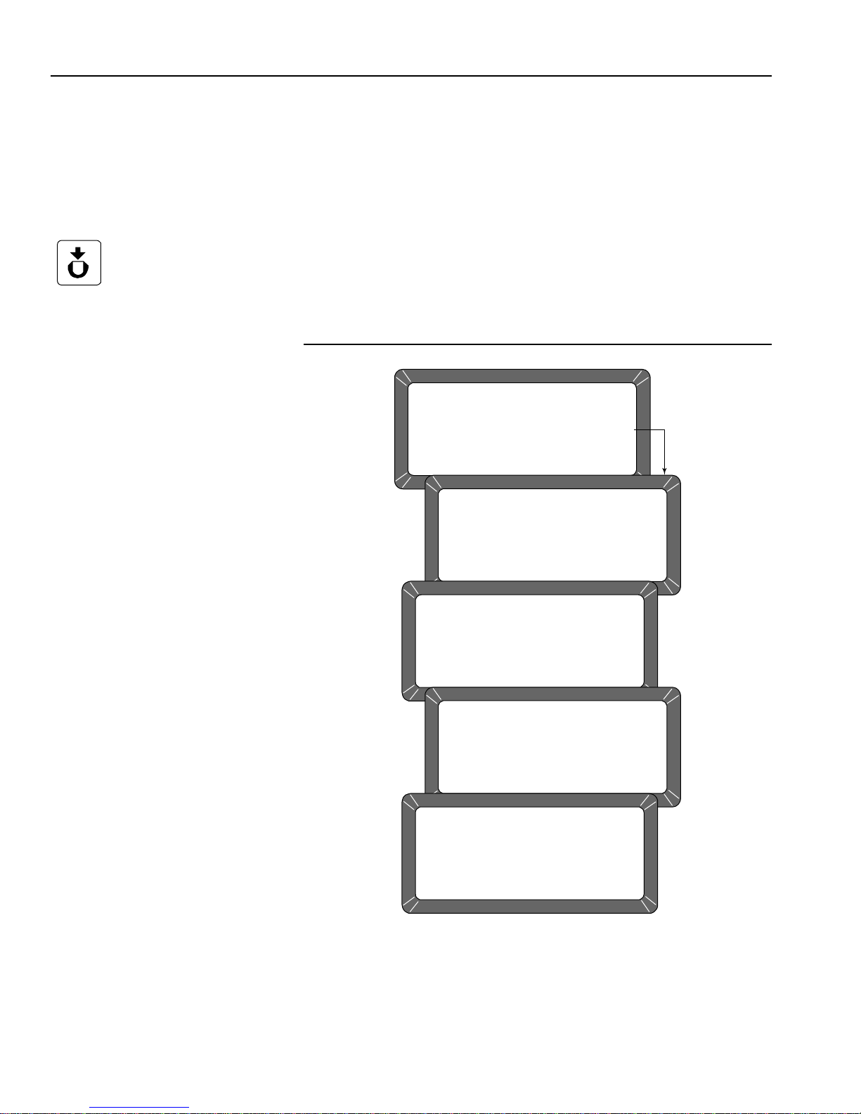
OPERATOR’S MANUAL
TESTS MENU
1: non-active
2: COM1
3: COM2 TRANSMIT
4: non-active
SELECT ITEM NUMBER
(NEXT PAGE: STATUS)
5: DISPLAY
6: DIAGNOSTIC MODE
7: TEST NET WORK MODE
8: PARAMETERS MENU
PERFORMING SELF CHECKS
PLEASE WAIT
TEST NETWORK MODE
ID: __
PRESS LOAD TO BEGIN
TEST NETWORK MODE
ID: __
MEASURING
PLEASE WAIT
TEST NETWORK MODE
ID: __
D1: 0.0
D2: 14.3
D3: 0.0
D4: 222.7
TEST NETWORK MODE
DATE: 09/15/13 TIME 15: 38: 53
ID:
Load Key
TEST NETWORK MODE (7 KEY)
This mode is used by trained, authorized personnel in troubl eshoo ting. Th e
screens and printout are shown for reference only.
To Access the TEST NETWORK:
1. Press the 7 key - TEST NETWORK MODE (Figure 61). The Please
Wait screen appears followed by the Press Load To Begin screen.
2. Press the Load key to start the measuring cycle. When the test is
complete, the results display and print automatically if a printer is
connected (Figure 62).
Figure 61
Displaying Test Network Mode Results
72 TEST UNIT PERFORMANCE
GAC® 2100 Grain Analysis Computer (Blue, Gray, Agri Models)
11001-1688-201609

OPERATOR’S MANUAL
05/18/13 09:18:59
ID:
NF: 490
NE: 490
D1: 0,0
D1CF: 15000
D1CE: 15000
D2: 14,4
D2CF: 14853
D2CE: 14853
D3: 0,0
D4: 204,3
D4TF: 20,43
D4TE: 20,39
SELECT TEST NUMBER
DICKEY-JOHN,
CORP. GAC2100
Figure 62
Test Mode Printout
VIEW/PRINT PARAMETERS (8 KEY)
Print Key
Previous Page Key
GAC® 2100 Grain Analysis Computer (Blue, Gray, Agri Models)
11001-1688-201609
The Parameters menu (8 key) operates similarly to the Service menu
located under the Setup menu. The major difference is the inability to edit
values in these screens. However , the View Factory Mode screen is useful
in viewing the number of currently stored errors in memory.
To View the Parameters Menu:
1. At the Main menu, press the 5 key.
1. Press the 8 key from the T ests menu and pr ess the Parameters menu.
This menu displays the unit parameters.
2. To print the values shown on the screen, select any menu followed by
the Print key. A printout of all the screens results (Figure 64). Item 6
also prints all stored errors.
3. When finished viewing the screens, select the Previous Page key to
return to the Tests menu.
TEST UNIT PERFORMANCE 73

OPERATOR’S MANUAL
TESTS MENU
1: non-active
2: COM1
3: COM2 TRANSMIT
4: non-active
SELECT ITEM NUMBER
(NEXT PAGE: STATUS)
5: DISPLAY
6: DIAGNOSTIC MODE
7: TEST NETWORK MODE
8: PARAMETERS MENU
PARAMETERS MENU
1: VIEW TEMPERATURE CONSTANTS
2: VIEW EMPTY CELL WEIGHT COUNTS
3: VIEW WEIGHT CONSTANTS
4: VIEW CAC/TWCC
5: VIEW SERIAL NUMBER
6: VIEW FACTORY MODES
SELECT TEST NUMBER (NEXT PAGE: STATUS)
VIEW FACTORY MODES
BURN IN MODE : OFF
ERROR STORING : ON
!! ERRORS HAVE BEEN STORED !!
VIEW SERIAL NUMBER
S/N: 1716-23601
VIEW CAC/TWCC
CALIB ADJ CONSTANT: 0.9870
TWCC: 0.9870
VIEW WEIGHT CONSTANTS
POINT WEIGHT RATIO
1 0.000 1.00000
2 61.500 1.02754
3 120.400 1.05453
4 181.800 1.08340
5 240.600 1.11179
6 300.300 1.14108
VIEW EMPTY CELL WEIGHT COUNTS
EMPTY CELL WEIGHT COUNTS: 40399
VIEW TEMPERATURE CONSTANTS
REFERENCE TEMPERATURE: 25.00
REFERENCE VOLTAGE : 1.1560
Blue S/N
AGRI/Gray S/N: 1737-23601
#4. TWCC Blue
Model
#4. TWCC Blue
Model
Figure 63
Viewing Parameters Menu
74 TEST UNIT PERFORMANCE
GAC® 2100 Grain Analysis Computer (Blue, Gray, Agri Models)
11001-1688-201609

OPERATOR’S MANUAL
05/18/16 09:59:59
S/N: 1716-23601
REF TEMP: 25,00
REF VOLT: 1,1560
EC COUNT: 40399
WEIGHT TABLE:
1 0,000 1,00000
2 61,500 1,02754
3 120,400 1,05453
4 181,800 1,08340
5 240,600 1,11179
6 300,300 1,14108
CAC: 1,0000
IC: 1122
BURN IN MODE: OFF
ERROR STORING: ON
CURRENT ERRORS
===================
ERROR 2
05/04/16 18:42:2
05/17/16 16:50:4
5
50134
SELECT TEST NUMBER
Figure 64
Parameters Value Printout
GAC® 2100 Grain Analysis Computer (Blue, Gray, Agri Models)
11001-1688-201609
TEST UNIT PERFORMANCE 75

OPERATOR’S MANUAL
76 TEST UNIT PERFORMANCE
GAC® 2100 Grain Analysis Computer (Blue, Gray, Agri Models)
11001-1688-201609

OPERATOR’S MANUAL
Fuses
Jumper Bar
Fuse Block
Cover
Load Key
Unload Key
Previous Page Key
OPERATOR MAINTENANCE
CELL CLEANING - DAILY
1. From the Main menu, select the 5-key to display the Tests menu. Then
select the 6-key to display the Diagnostics menu.
2. When the Diagnostics menu displays select the Load key. The
hopper doors open and remain open until the Unload key is selected.
3. Use the brush supplied in the accessory kit to clean the inside of the
grain cell.
4. Slide the GAC 2100 to the front of the worktable and remove the grain
drawer. Reach inside and very carefully clean the strike-off arm spring.
Before performing step 5 ensure that all fingers or other foreign
objects are not in cell area.
5. Press the Unload key. The cell will rotate 180 degrees to dump the
residue from the cell cleaning procedure. The hopper doors will close.
6. Press the Previous Page key twice to return to the Main menu.
FUSE REPLACEMENT
1. Disconnect the line cord from the rear of the unit.
2. Use a small-bladed screwdriver or similar tool to remove the cover and
fuse block assembly.
3. Replace the blown fuse with a 1 Amp Slo-Blo fuse (Fuse Size = 5mm
(0.197") dia. x 20 mm (0.787") long.
4. Reinstall fuse block assembly and cover.
Figure 65
Fuse Block Assembly
GAC® 2100 Grain Analysis Computer (Blue, Gray, Agri Models)
11001-1688-201609
OPERATOR MAINTENANCE 77

OPERATOR’S MANUAL
ERROR CODES
The GAC 2100 contains a microprocessor to control the grain sample
measurements and self-checks to determine the integrity of the internal
electronics. If any limit is exceeded or malfunctions occur, an error code
displays.
Error
1 The empty cell self-check reading is out of limits. Dump the cell and verify it is empty.
2 The empty cell weight reading is out of limits. Dump the cell and verify it is empty.
3 The unload mechanism has malfunctioned. Check the cell position and verify it is free to operate.
4 The strike-off mechanism has malfunctioned. Check dra we r and press the Unload key. Verify the cell and
5 An invalid calibration is referenced. Reselect the same grain or select a new grain and retry. If the
6 The moisture reading exceeds the upper limit. Select a new grain and retry.
7 The moisture reading exceeds the lower limit. Select a new grain and retry.
8 The empty cell ambient temperature has
9 The sample temperature exceeds its limit. Allow the sample to either cool down or warm up, then retry.
10 The difference in temperature between empty cell
11 Test weight exceeds stored average bulk density
12 A system memory error occurred. Turn the power OFF for at least 5 seconds; power system ON. If
13 An onboard RAM memory error has occurred. Turn the power OFF for at least 5 seconds; turn power system
14 NOT USED
15 The real-time clock battery is faulty. Contact a DICKEY-john represent ative for assistance.
Probable Cause
exceeded its limit.
ambient and full cell condition exceeds it s limits.
value by more than +20 percent or -30 percent.
Corrective Action
strike-off arm are free to operate.
condition continues to occur, contact a DICKEY-john
representative for assistance.
Allow the GAC 2100 to reach normal operating temperature.
Change the appropriate conditions and retry.
Use a more representative sample.
the condition continues, contact a DICKEY-john representative.
ON. If the condition continues, contact a DICKEY-john
representative for assistance.
78 OPERATOR MAINTENANCE
GAC® 2100 Grain Analysis Computer (Blue, Gray, Agri Models)
11001-1688-201609

OPERATOR’S MANUAL
Table 2. COM1 Programmable Options
Function Option Hex
Output Format PRN 20
PRN 80
TST 20
PRN 81
CSV 01
PRN 21
Line Terminator LF (Line Feed) 0A
CR (Carriage Return 0D
LF + CR 0A, 0D
CR + LF 0D, 0A
Data Setup 300
Baud Rate 600
1200
2400
4800
9600
19200
Control Busy Ignore
Active (+)
Active ( Ð)
Control DTR Ignore
Active
APPENDIX A: COMMUNICATION PORTS
COM1 PORT OPTIONS
NOTE: COM 1 port requires a standard
DTE/DCE RS 232 cable without
a null modem when connecting
to a printer or computer.
The COM1 Port (refer to Table 2) is a serial port conforming to the EIA/TIA
RS-232-E standard and configured as Data Communication Equipment
(DCE). Data out is RS-232-E levels and parity with adjustable Format, Data
Setup and Control.
GAC® 2100 Grain Analysis Computer (Blue, Gray, Agri Models)
11001-1688-201609
COM1 PIN ASSIGNMENT DETAILS
COM1 (refer to Table 3) is configured as Data Communication Equipment
(DCE).
Protective Ground (pin 1) – Electrically connected to frame.
Received Data (pin 3) – Transmitted data from the GAC 2100.
Data Set Ready (pin 6) – ON (positive voltage) whenever the
GAC 2100 is powered.
Signal Ground (pin 7) – Common reference for all other COM1 sig nals.
Received Line Signal Detector (pin 8) – ON (positive voltage)
whenever the GAC 2100 is powered.
Busy (pin 11) – Gates the transmission of dat a from the GAC 2100. The
COM1 Control Lead Setup screen may be configured ACTIVE (+),
ACTIVE (–) or IGNORE. When the line is inactive, up to 2048
characters are buffered. If not co nnected, configure this line as
IGNORE.
APPENDIX A: COMMUNICATION PORTS 79

OPERATOR’S MANUAL
Table 3. COM1 Connector Pins Identification
Pin Number Designation Signal Name Direction
1 AA Protective Ground NA
3 BB (RxD) Received Data To Device
6 CC (DSR) Data Set Ready To Device
7 AB Signal Ground NA
8 CF (RLSD) Received Line To Device
Signal Detector
11 Busy To GAC 2100
20 CD (DTR) Data Terminal Ready To GAC 2100
Table 4. COM2 Programmable Options
Function Option Hex
Output Format PRN 20
PRN 80
TST 20
PRN 81
CSV 01
PRN 21
Line Terminator LF (Line Feed) 0A
CR (Carriage Return 0D
LF + CR 0A, 0D
CR + LF 0D, 0A
Data Setup 300
Baud Rate 600
1200
2400
4800
9600
19200
Data Bits 7 or 8
Parity None, Even or Odd
Stop Bits 1 or 2
Control MODE Transmit Only
Auto Answer
Control RTS On (+)
Auto
Control DSR Ignore
Active
Data Terminal Ready (pin 20) – Indicates the connected device is not
available. The COM1 Control Lead Setup screen configures this line
as ACTIVE or IGNORE. If configured ACTIVE, an OFF condition
(negative or zero voltage) inhibits the transmission of data from the
GAC 2100. Results display but are not buffered for output on COM1. If
not connected, this line should be configured as IGNORE.
NOTE: COM 2 Baud Rate will always
80 APPENDIX A: COMMUNICATION PORTS
remain at 115200, Data Bits at
8, Parity at None, and Stop Bits
at 1 although the option to
change are in the manual.
COM 2 requires an RS 232 null
modem when connecting to a
computer or printer.
COM2 PIN ASSIGNMENT DETAILS
COM2 (refer to Table 5) is configured as Data Terminal Equipment (DTE).
Protective Ground (pin 1) – Electrically connected to frame.
Transmitted Data (pin 2) – Data is transmitted from this pin.
Received Data (pin 3) – Data is received on this pin.
GAC® 2100 Grain Analysis Computer (Blue, Gray, Agri Models)
11001-1688-201609

OPERATOR’S MANUAL
Table 5. COM2 Connector Pins Identification
Pin Number Designation Signal Name Direction
1 AA Protective Ground NA
2 BA (TxD) Transmitted Data To Device
3 BB (RxD) Received Data To GAC 2100
4 CA (RTS) Request To Send To Device
5 CB (CTS) Clear To Send To GAC 2100
6 CC (DSR) Data Set Ready To GAC 2100
7 AB Signal Ground NA
8 CF (RLSD) Received Line to To GAC 2100
Signal Detector
20 CD (DTR) Data Terminal Ready To Device
22 CE (Rl) Ring Indicator To GAC 2100
Request T o Send (pin 4) – Configured ON (positive volt age) whenever
unit is powered or to be ON (positive voltage) only when there is dat a in
the COM2 buffer to be transmitted. Use the COM2 Control Lead Setup
screen to configure this line.
Clear To Send (pin 5) – Gates transmission of data from the
GAC 2100. This line must be ON (positive voltage) to obtain data on
COM2. If an appropriate signal is not available from the connected
device, connect this pin directly to REQUEST TO SEND (pin 4). When
the line is inactive, up to 2048 characters are buffered.
Data Set Ready (pin 6) – Notifies the GAC 2100 that the connected
device is not available. The COM2 Control Lead Setup screen
configures this line as active or ignored. If configured as ACTIVE, an
OFF condition (negative or zero voltage) inhi bits the transmission of
data from the GAC 2100. Results display but are not buffered for output
on COM2. If not connected, this line should be configured as
IGNORED.
Signal Ground (pin 7) – Common ground reference for all oth er COM2
signals.
Received Line Signal Detector (pin 8) – Currently not used.
Data Terminal Ready (pin 20) – ON (positive voltage) whenever the
GAC 2100 is powered.
Ring Indicator (pin 22) – Currently not used.
GAC® 2100 Grain Analysis Computer (Blue, Gray, Agri Models)
11001-1688-201609
APPENDIX A: COMMUNICATION PORTS 81

OPERATOR’S MANUAL
82 APPENDIX A: COMMUNICATION PORTS
GAC® 2100 Grain Analysis Computer (Blue, Gray, Agri Models)
11001-1688-201609

Dealers have the responsibility of calling to the attention of their customers the following
warranty prior to acceptance of an order from their customer for any DICKEY-john product.
DICKEY-john® WARRANTY
DICKEY-john warrants to the original purchaser for use that, if any part of the product
proves to be defective in material or workmanship within one year from date of original
installation, and is returned to DICKEY-john within 30 days after such defect is discovered,
DICKEY-john will (at our option) either replace or repair said part. This warranty does not apply
to damage resulting from misuse, neglect, accident, or improper installation or maintenance; any
expenses or liabilit y for repairs made by outside parties without DICKEY-john’s written consent;
damage to any associated equipment; or lost profits or special damages. Said part will not be
considered defective if it substantially fulfills the performance expectations. THE FOREGOING
WARRANTY IS EXCLUSIVE AND IN LIEU OF ALL OTHER WARRANTIES OF
MERCHANTABILITY, FITNESS FOR PURPOSE, AND OF ANY OTHER TYPE, WHETHER
EXPRESS OR IMPLIED. DICKEY-john neither assumes nor authorizes anyone to assume f or it
any other obligation or liability in connection with said part and will not be liable for
consequential damages. Purchaser accepts these terms and warranty limitations unless the
product is returned within fifteen days for full refund of purchase price.
For DICKEY- john Service Department, call
1-800-637-3302 in either the U.S.A. or Canada
Headquarters:
5200 Dickey-john Road, Auburn, IL USA 62615
TEL: 217 438 3371, FAX: 217 438 6012, WEB: www.dickey-john.com
Europe:
DICKEY-john Europe S.A.S, 165, boulevard de Valmy, 92706 – Colombes – France
TEL: 33 (0) 1 41 19 21 80, FAX: 33 (0) 1 47 86 00 07 WEB: www.dickey-john.com
Copyright 2016 DICKEY-john
Specifications subject to change without notice.

®
2100 GRAIN
ANALYSIS COMPUTER
DICKEY-john Sales
800-637-2952
agsales@dickey-john.com
DICKEY-john Technical Support
800-637-3302
service@dickey-john.com
Europe Sales and Technical Support
+33 1 41 19 21 80
europe@dickey-john.com
Operator’s Manual
®
5200 Dickey-john Road
SINCE 1966
Auburn, IL 62615
www.dickey-john.com
217-438-3371
217-438-6012 fax
©2016 DICKEY-john Corporation
DICKEY-john, the DICKEY-john Logo and GAC are
registered trademarks of DICKEY-john Corporation.
11001-1688-201609
 Loading...