

Page 1
DIAMOND VIEW 2115E
Colour Monitor
21 (53.3 cm) CRT Size
Page 2

Table of Contents
1 Introduction ............................................................................. 1
Unpacking the Package .................................................... 1
Features .............................................................................. 2
Power Management ........................................................... 3
Factory Preset Timings...................................................... 3
2 Installing the Monitor ................................... 4
Connecting the Signal Cable ............................................ 5
3 Adjusting the Picture .................................. 8
Making Adjustments .......................................................... 9
Auto key (Auto Calibration key ) ........................................................... 9
Hot Keys............................................................................................... 9
OSD Operation ................................................................................... 10
Main Menu 1 Display Control ............................................................. 10
Main Menu 2 Color Control................................................................. 14
Main Menu 3 Advanced Display Control .............................................. 15
Timing Setting .................................................................. 20
Pin Assignments .............................................................. 21
D-SUB Connectors.............................................................................. 21
BNC Connectors ................................................................................. 22
4 Troubleshooting.................................................. 2 3
Need More Help?.............................................................. 25
5 Specifications ....................................................... 2 6
Page 3
iii
Copyright
Copyright (c) 2001 by Mitsubishi Electric Australia Pty. Ltd. All rights reserved.
No part of this publication may be reproduced, transmitted, transcribed, stored
in a retrieval system or translated into any language or computer language, in
any form or by any means, electronic, mechanical, magnetic, optical, chemical,
manual or otherwise, without the prior written permission of Mitsubishi Electric
Australia Pty. Ltd.
Disclaimer
Mitsubishi Electric Australia Pty. Ltd. makes no representations or
warranties, either expressed or implied, with respect to the contents hereof
and specifically disclaims any warranties, merchantability or fitness for any
particular purpose. Further, Mitsubishi Electric Australia Pty. Ltd. reserves
the right to revise this publication and to make changes from time to time in
the contents hereof without obligation of Mitsubishi Electric Australia Pty.
Ltd. to notify any person of such revision or changes.
Diamond View is a registered trademark of Mitsubishi Electric Australia Pty.
Ltd. Microsoft and Windows are registered trademarks of Microsoft Corporation.
All other trademarks remain the property of their respective owners.
Reference Information
For future reference, write the following information about your monitor in
the space below. The serial number is on the back of the product or on
the bottom of its stand.
Monitor Information
Product Name: 2115E
Serial Number:
Date of Purchase:
Dealer Information
Dealer:
T elephone Number:
Address:
Page 4

iv
Safety Instructions
◆The AC plug isolates this equipment from the AC supply.
◆ Unplug this product from the wall outlet before cleaning. Do not use liquid
cleaners or aerosol cleaners. Use a damp cloth for cleaning.
◆ Slots and openings in the cabinet and the back or bottom are provided for
ventilation. They must not be blocked or covered. This product should never
be placed near or over a radiator or heat register, or in a built-in installation
unless proper ventilation is provided.
◆ This product should be operated from the type of power indicated on the
marking label. If you are not sure of the type of power available, consult your
dealer or local power company.
◆ This product should be operated with a 3-wire grounding-type plug, a plug
having a third (grounding) pin. This plug will only fit into a grounding-type
power outlet. This is a safety feature. If you are unable to insert the plug into
the outlet, contact your electrician to make the necessary outlet changes.
◆ Never push objects of any kind, or spill liquid of any kind into this product.
◆ Do not attempt to service this product yourself, as opening or removing
covers may expose you to dangerous voltages or other risks. If any above
mentioned misuse or other accident (dropping, mis-operations) occurs, contact qualified service personnel for servicing.
◆ Use only the proper type of power supply cord set (provided in your PC box)
for this unit. It should be a detachable type: UL listed/CSA certified, type
SVT/SJT, VDE approved or its equivalent.
◆ The power supply cord serves as a power disconnect device for pluggable
equipment. The socket outlet shall be installed near the equipment and
shall be easily accessible.
Page 5
v
Maintenance
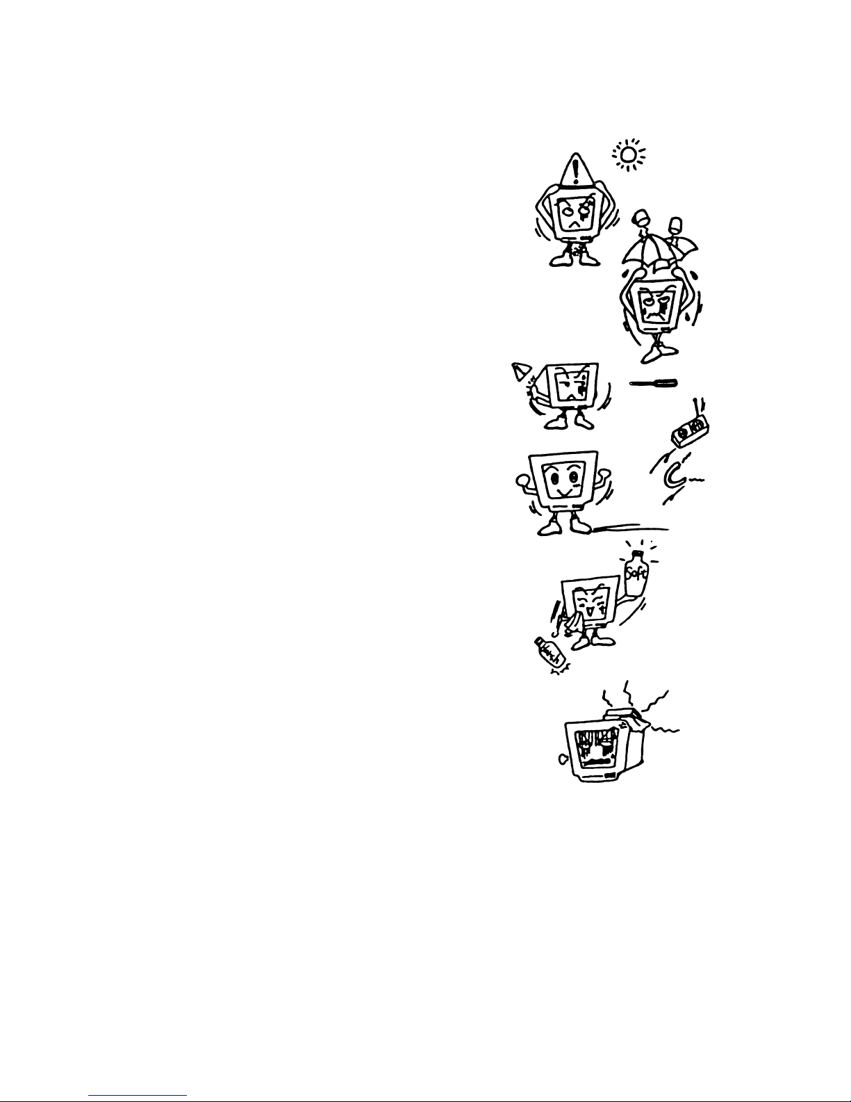
◆ Do not expose the monitor to direct
sunlight or heat.
◆ Do not spill liquid onto the monitor
◆ Do not attempt to open the monitor . You
may be hurt by electric shock. For
service, call your place of purchase.
Opening your monitor may also void
warranty.
◆ Do not use your monitor when magnets
or electronic products are operating
nearby.
◆ Do not use harsh chemicals or strong
cleaning solvents to clean the monitor
screen. Wipe it with clean, soft clothes
applied with mild solution.
◆ Do not place anything on your monitor.
Bad ventilation may elevate temperature
in the monitor
Page 6
1
1 Introduction
Unpacking the Package
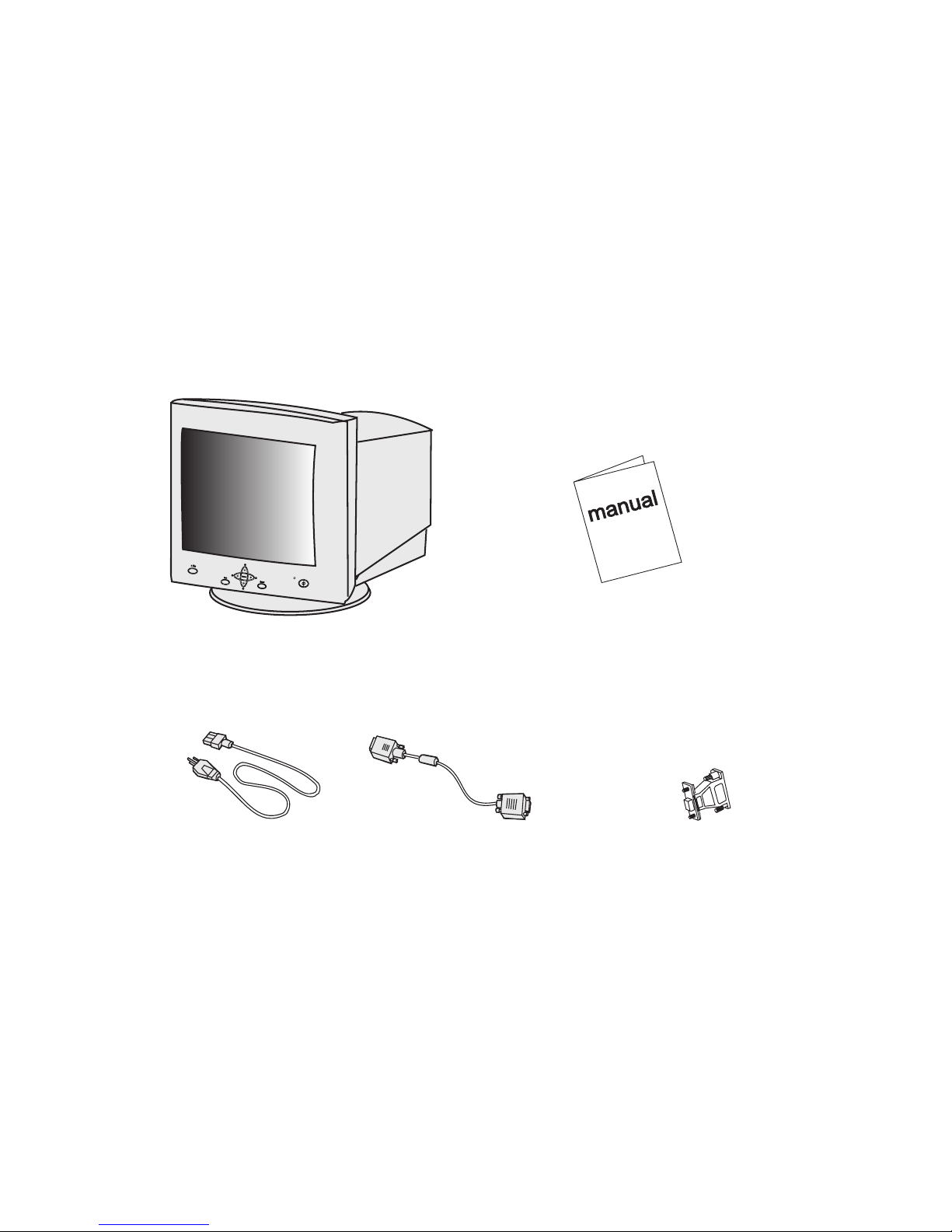
Check following items. If they are missing or damaged, consult your place of
purchase immediately.
Colour monitor User’s ma n u a l
Power cord 15-pin D-SUB Macintosh adaptor
signal cable
? Locate the model name and the serial number labeled on the back
of your monitor. Write down the related information of your
monitor and dealer in the space on page iii for future reference.
Page 7

2
Features
◆
Super-fine Dot PitchSuper-fine Dot Pitch
Super-fine Dot PitchSuper-fine Dot Pitch
Super-fine Dot Pitch
With 0.25 mm dot pitch, the Diamond View 21 15E colour monitor provides strikingly sharp high-resolution images up to 1920 x 1440 pixels.
◆
Wide Auto Scanning RangeWide Auto Scanning Range
Wide Auto Scanning RangeWide Auto Scanning Range
Wide Auto Scanning Range
The horizontal frequency range of 30 to 115 KHz supports 1600 x 1200 pixel
resolution at a flicker-free 85 Hz refresh rate.
◆
Auto keyAuto key
Auto keyAuto key
Auto key
(Automatic picture adjustment)(Automatic picture adjustment)
(Automatic picture adjustment)(Automatic picture adjustment)
(Automatic picture adjustment)
Automatically adjust the image size and position with the press of one button.
◆
Low radiationLow radiation
Low radiationLow radiation
Low radiation
The Diamond View 2115E meets the low radiation requirements of the TCO’99
standard.
◆
Plug’n Play CompatibilityPlug’n Play Compatibility
Plug’n Play CompatibilityPlug’n Play Compatibility
Plug’n Play Compatibility
With support for the VESA DDC-2B standard, the 21 15E is compatible with the
Plug’n Play features of Windows® 95, 98, 2000, ME® and XP.
Page 8

3
Power Management
The Power management of this monitor complies with these VESA
power saving modes:
Mode Power Horizontal Vertical LED
Consumption Sync Sync
On < 150W Max. On On Green
Stand-by < 5 W Off On Amber
Suspend < 5 W On Off Amber
Off < 5 W Off Off Amber
Factory Preset Timings
Resolution V ertical Frequency Horizontal Frequency
(Hz) (KHz)
640 x 400 70 31.47
640 x 480 60 31.47
800 x 600 75 46.88
1024 x 768 75 60.02
1024 x 768 85 68.68
1280 x 1024 75 79.98
1280 x 1024 85 91.15
1600 x 1200 75 93.75
1600 x 1200 85 106.00
1920 x 1440 75 112.50
** All above timings are non-Interlace timings.
Page 9
4
2 Installing the Monitor
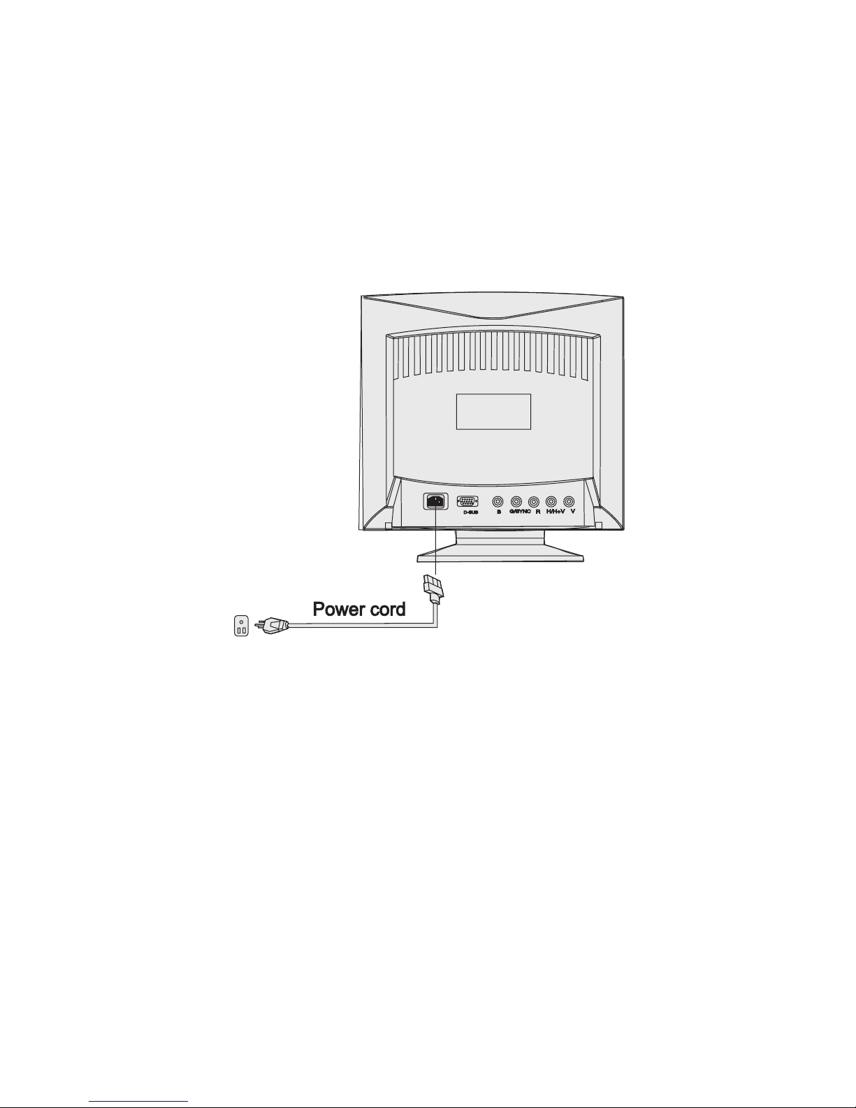
This monitor is equipped with an auto sensing power supply for voltage range of
100~240V AC, 50~60Hz.
To install the monitor:
1) Make sure that the system power is turned off.
2) Connect the power cord to the monitor and attach it to power source.
3) Turn the power switch on at the wall socket.
4) Turn the computer and the monitor on.
Page 10
5
Connecting the Signal Cable
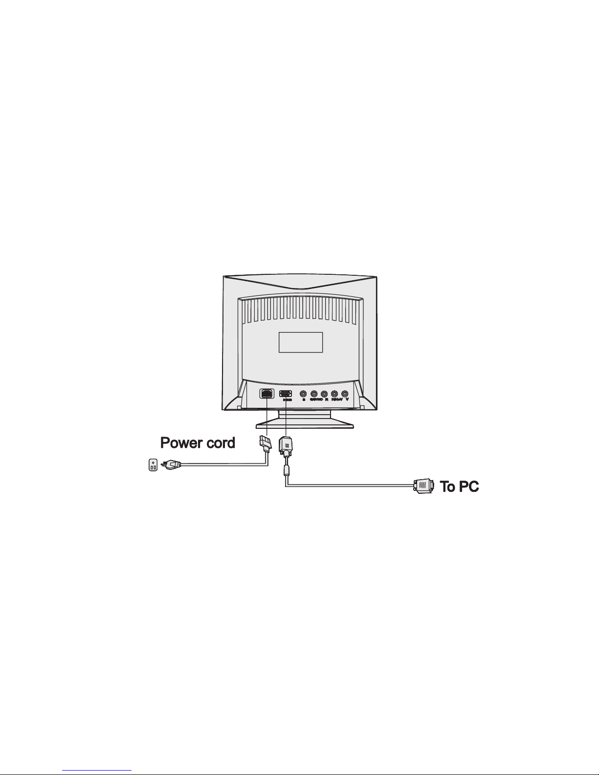
Your 2115E monitor provides both 15 pin VGA type (D-SUB) and BNC signal
connectors. The D-SUB or BNC signals are automatically detected by the monitor.
✏ Connecting through D-SUB signal connector
1) Make sure that the system power is turned off.
2) Connect the computer end of the D-SUB cable to the 15-pin output connector
on the video board of your computer.
3) Connect the monitor end of the BNC signal cable to the BNC plugs at the
back of the monitor. Make sure that you connect each plug to the correct
socket.
Page 11
6
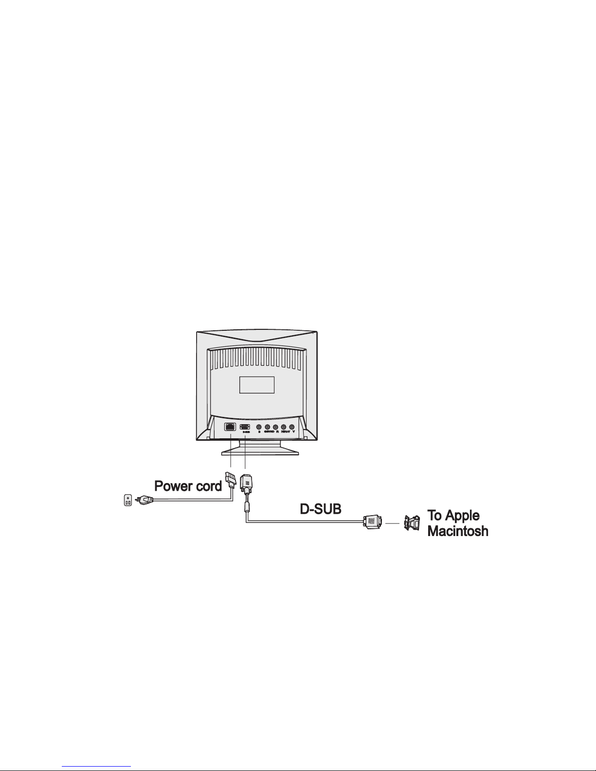
✏ Connecting to An Apple
If you need to connect the monitor to an older-style Apple Macintosh computer,
you will need to use the Macintosh adaptor included with your monitor. Before
connecting the adaptor please refer to the user's guide of the adaptor to set its
option switches. Plug the adaptor into the video signal port of your computer and
then connect the signal cable between the adaptor and the monitor.
Page 12
7
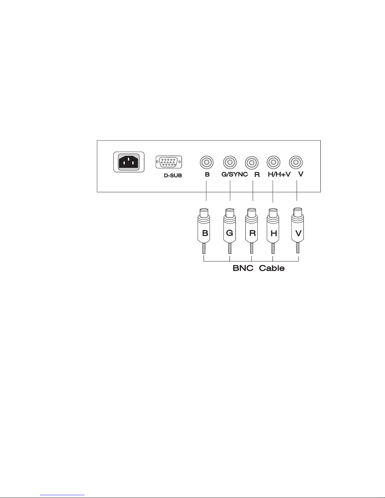
✏ Connecting through BNC Signal Connector
1) Make sure that the system power is turned off.
2) Connect the computer end of the BNC cable to the output connector on the
video board of your computer.
3) Connect the monitor end of the BNC cable to the BNC receptacle on the back
of the monitor.
Page 13
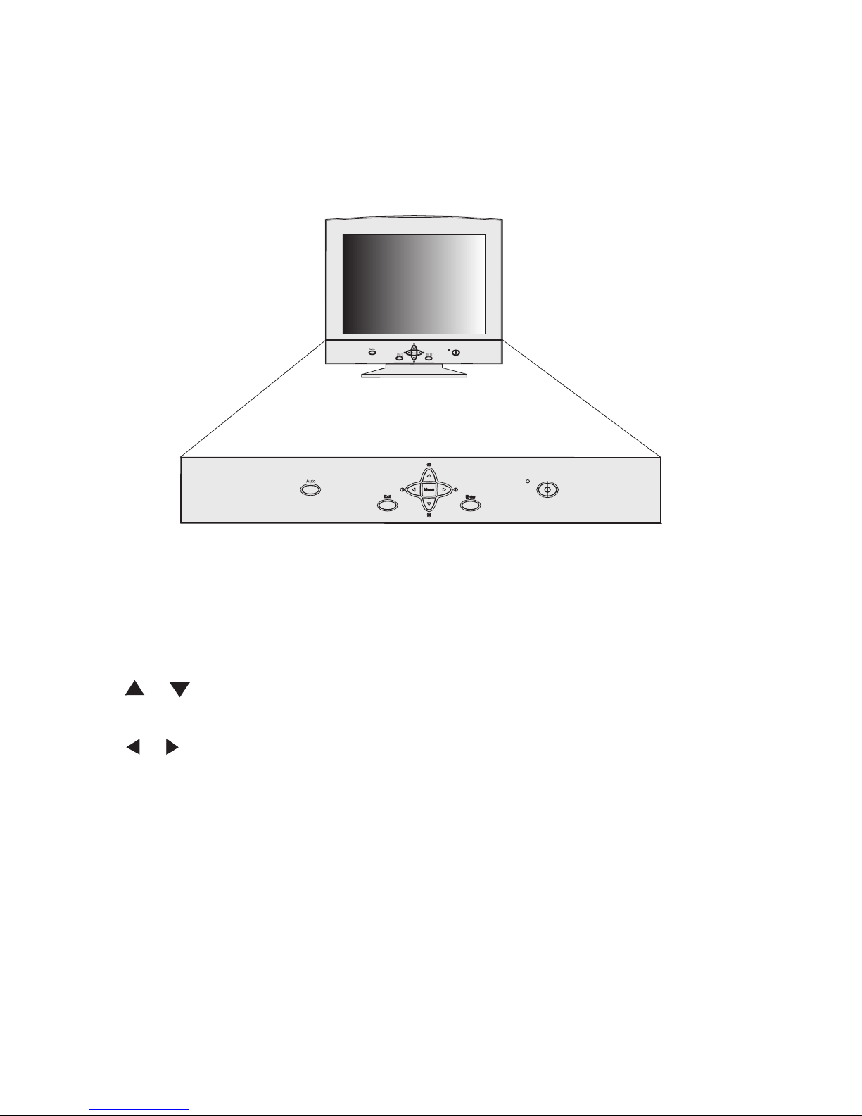
8
◆ Menu key : enters or changes Main menus. There are three main menus.
◆ Enter key : enters sub-menus or selects items.
◆ Exit key : goes back to main menus (auto save), or leaves OSD.
◆ & key : scrolls the light coloured bar up or down and represents
HOT KEY for brightness adjustment.
◆ & key : scrolls the light coloured bar left or right and represents
HOT KEY for contrast adjustment.
◆ Auto: performs automatic image adjustment.
3 Adjusting the Picture
Page 14
9
Making Adjustments
Auto key (Auto Calibration key )
Just push the Auto key to automatically optimise the display’s size and position.
No re-configuration or adjustment is needed when the display mode is changed.
Please note that the Auto function is not the same as "Reset" function. The
"Reset" function only works if the graphics signal is the same as the monitor’s
factory preset signal timings (please see page 3). The Auto function will work
with any graphics signal that the 2115E can display.
Hot Keys
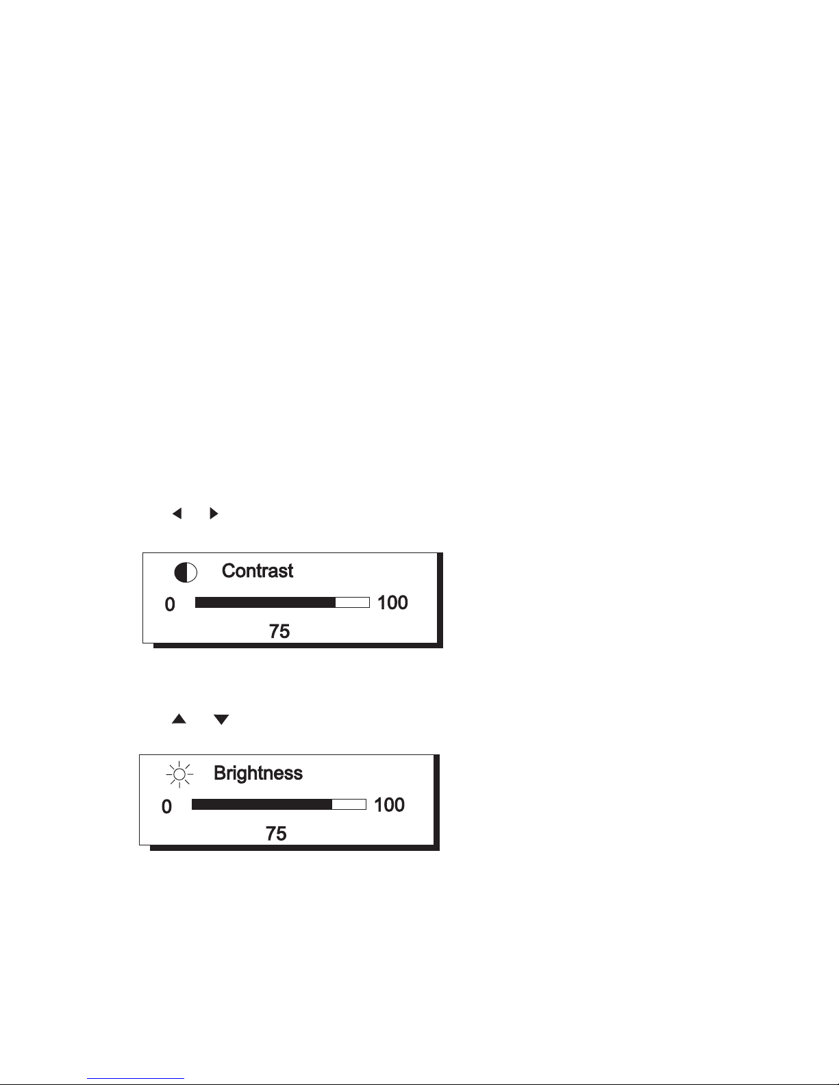
Press or to adjust contrast directly.
Press or to adjust brightness directly.
Page 15
10
OSD Operation
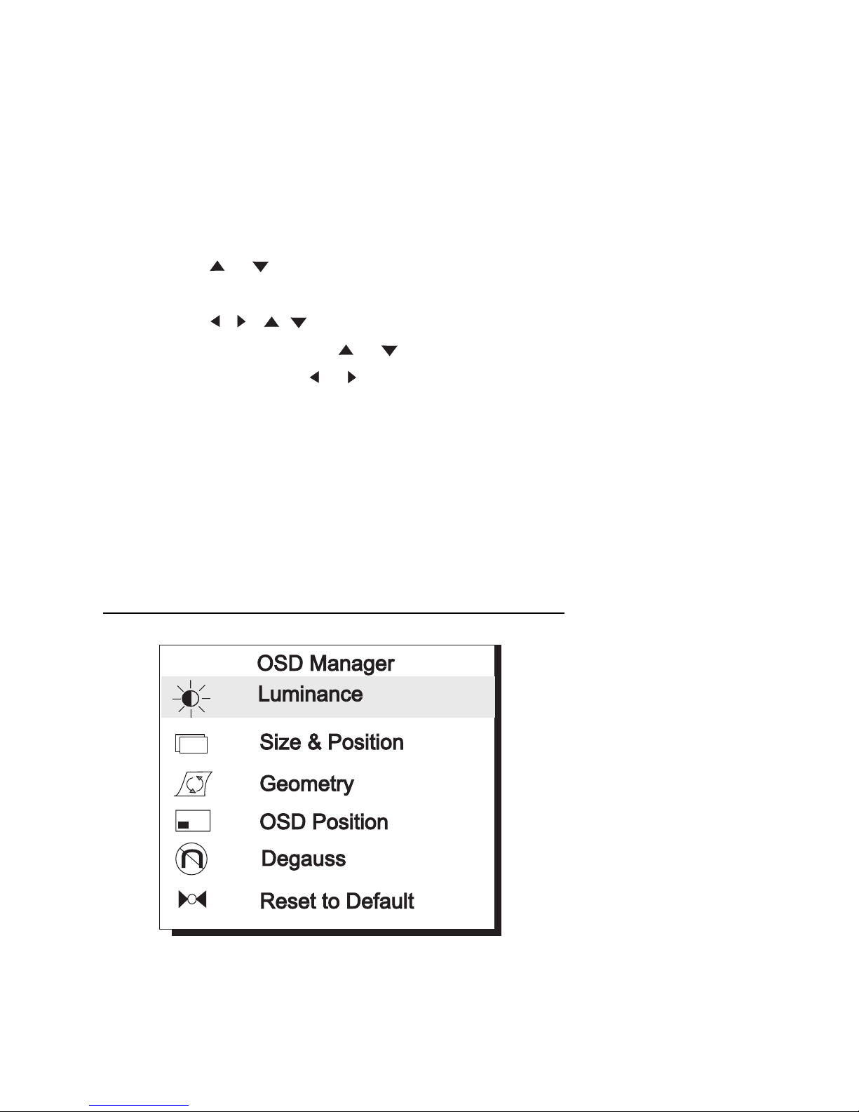
1 ) Press Menu to enter or change Main menus (there are three main
menus)
2) Press or to scroll light coloured bar to desired items.
3 ) Press Enter to enter sub-menus.
4) Press , ( , ) to do the adjustments. If the sub-menu contains
multiple items. Press or to scroll light coloured bar to desired
items. Then press or to adjust as required.
5) Press Exit to save and return to main menus.
6) Press Exit to save and leave OSD
? To reset the monitor to the factory default settings, please see page
15.
Main Menu 1 Display Control
Main menu 1 includes six items. Scroll the light coloured bar to the desired item
and press Enter to go to one of the sub-menus.
Page 16
11
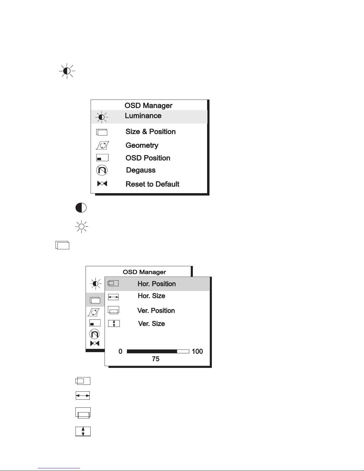
Contrast adjusts the difference between the light and dark areas.
Brightness adjusts the brightness of the display.
Size & Position
Display size and position adjustment
Hor. Position adjusts the horizontal position of the d isplay.
Hor. Size adjusts the width of the display.
Ver. Position adjusts the vertical position of the display .
Ver. S iz e adjusts the vertical height of the display.
Luminance
Contrast and Brightness adjustments
Page 17
12
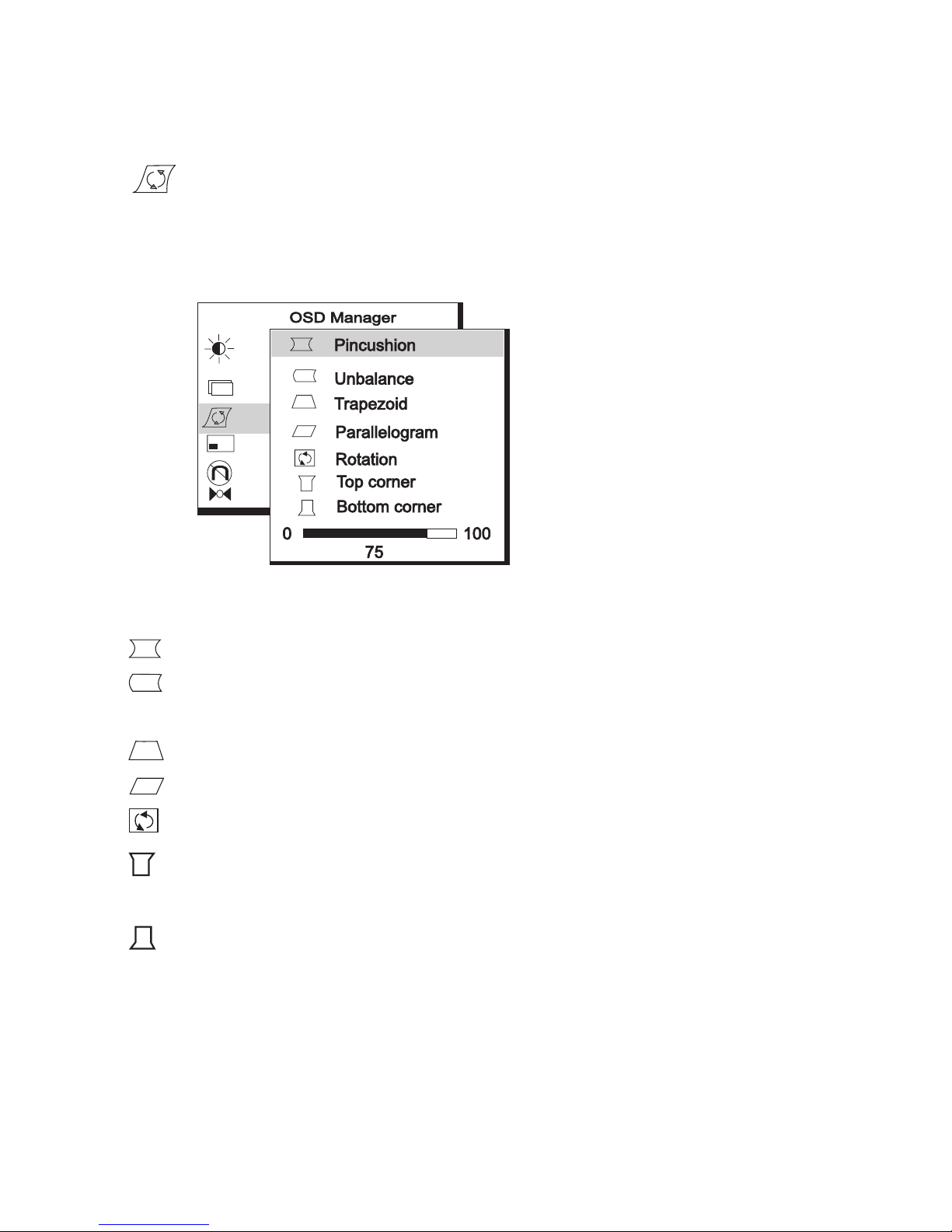
Geometry
Advanced geometry adjustments
Pincushion controls the straightness of the vertical edges of the display.
Unbalance adjusts balance when the sides of display are bowed
towards left or right
Trapezoid makes the vertical edges of the display parallel.
Parallelogram corrects image leaning left or right.
Rotation corrects screen tilt.
Top Corner adjusts the straightness of the vertical edges at the top
corners of the image.
Bottom Corner adjusts the straightness of the vertical edges at the
bottom corners of the image.
Page 18
13
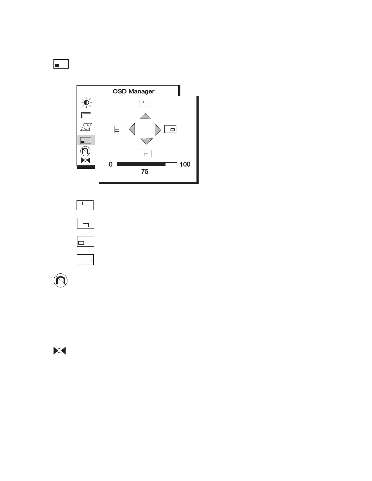
OSD Position
OSD position adjustments
moves the OSD menu position up.
moves the OSD menu position down.
moves the OSD menu position left.
moves the OSD menu position right.
Degauss
Manual Degauss. To eliminate color shading or impurity induced by re-
sidual magnetism. Press Enter to activate the manual Degauss function. Note
that the monitor automatically deguasses every time that it is turned on.
Reset to Default
Reset the monitor to the default factory settings including H/V position,
H/V size, Pincushion, Unbalance, Trapezoid, Parallelogram, Rotation, Corner,
H/V Convergence, H/V Moire. In order to reset the monitor to the factory default,
press Enter. You must be displaying one of the monitor’s factory preset graphics signal for this function to work (see page 3). Please see page 15 for details
about resetting the colour temperature and balance .
Page 19
14
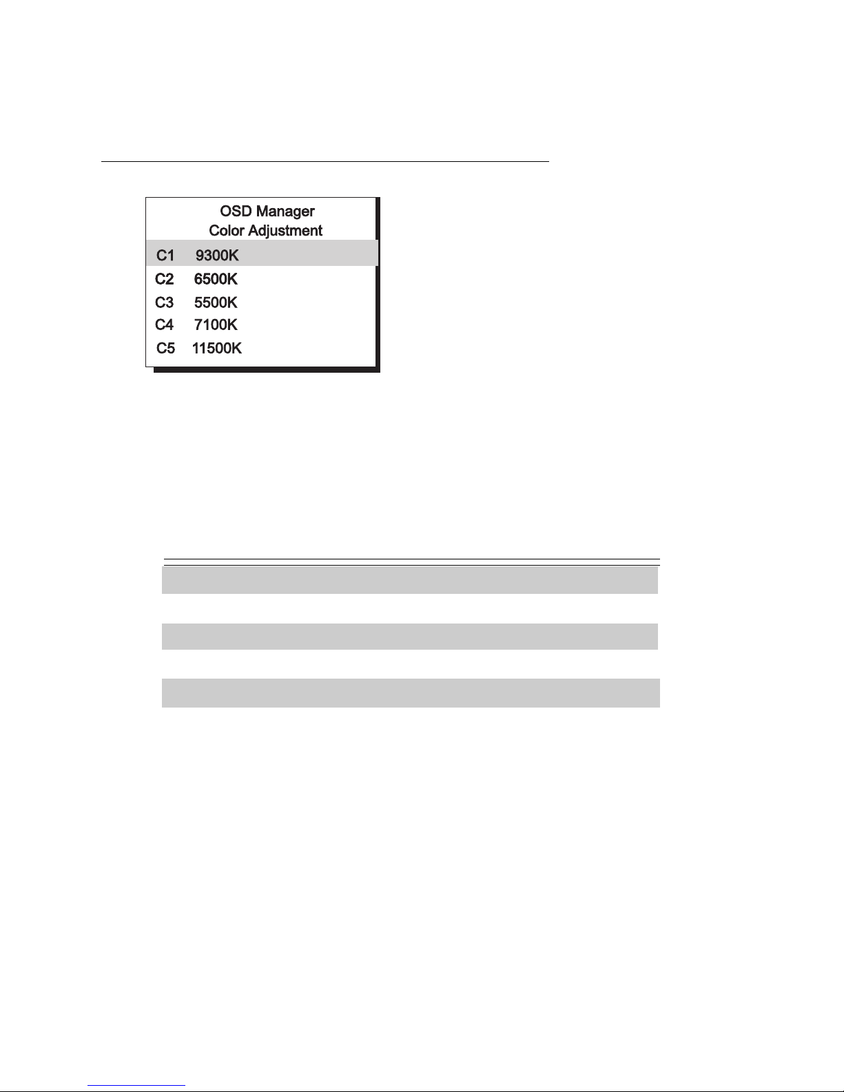
Main Menu 2 Color Control
This main menu is used to set the monitor’s colour balance. C1 ~ C5 are preset
colour temperatures that can be used to set the white point for different applications.
Factory Default Color Temperature
C1 9300K
C2 6500K
C3 5500K
C4 7100K
C5 11500K
Use the up and down arrows to select the desired coloured temperature. Press
Exit to save the setting and leave the OSD. Press the Enter key to adjust the
Red, Green and Blue colour balance.
Page 20
15
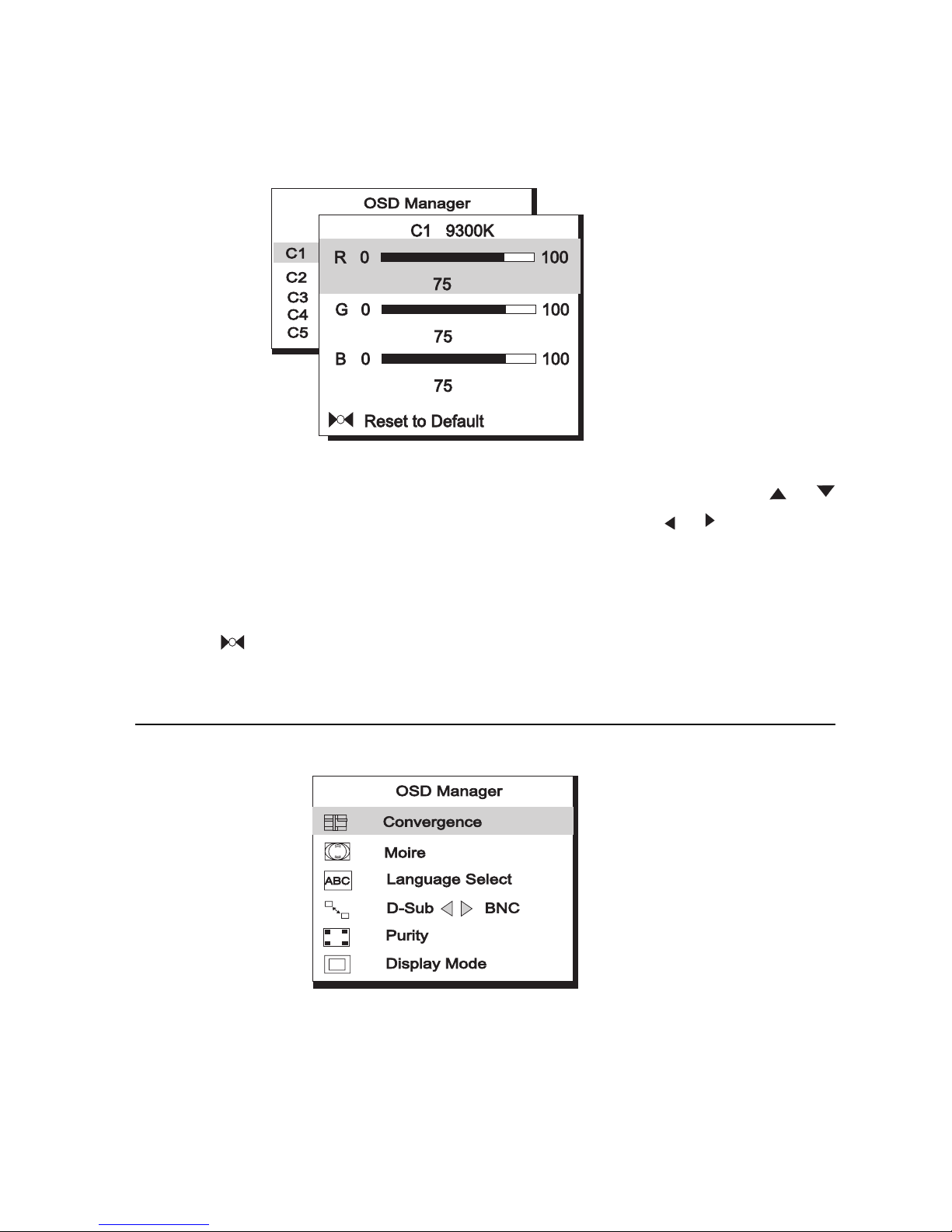
This sub-menu adjusts RGB (Red, Green, Blue) color balance. Press or
keys to scroll light coloured bar to desired items then press or key to do the
adjustments.
? To reset to factory default values, scroll light coloured bar to item
“
Reset to Default”.
Main Menu 3 Advanced Display Control
This main menu includes six items. Use the coloured bar to select desired item.
Press the Enter key to make an adjustment.
Page 21
16
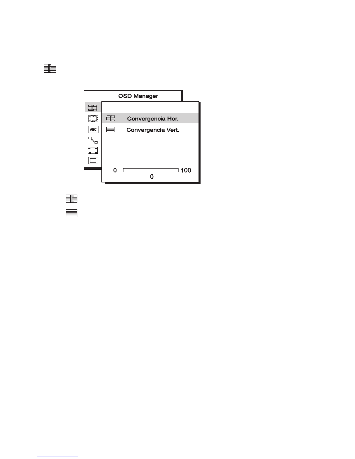
Convergence
Horizontal & Vertical Convergence adjustment
Hor. Convergence: adjusts Horizontal Convergence
V er. Convergence: adjusts V ertical Convergen ce
Convergence is the monitor's ability to precisely illuminate specific phosphors
and line them up properly in order to produce pure color. Displayed characters
and images may appear fuzzy or have tinges of red , green, or blue if the el ectron
beams do not converg e correctly.
The 2115E monit or provi des a converg ence adjustm ent. To proper ly adjust
convergence, it is best to ha ve an image that makes it easy t o see any convergence error. A black background with white letters or lines is recommended.
When adjusting convergenc e, look at t he adjustment across the whole screen.
When adjusting horizontal convergence, look at the left and right edges of vertical lines or characters. When adjusting vertical convergence, look at the top and
bottom edges of horizontal lines or characters. The monitor is properly adjusted
when the eff ects of red and bl ue ti nges are minim ized.
? The convergence adjustment adjusts the entire screen. It is not
possible to limit adjustment to specific screen areas.
Page 22
17
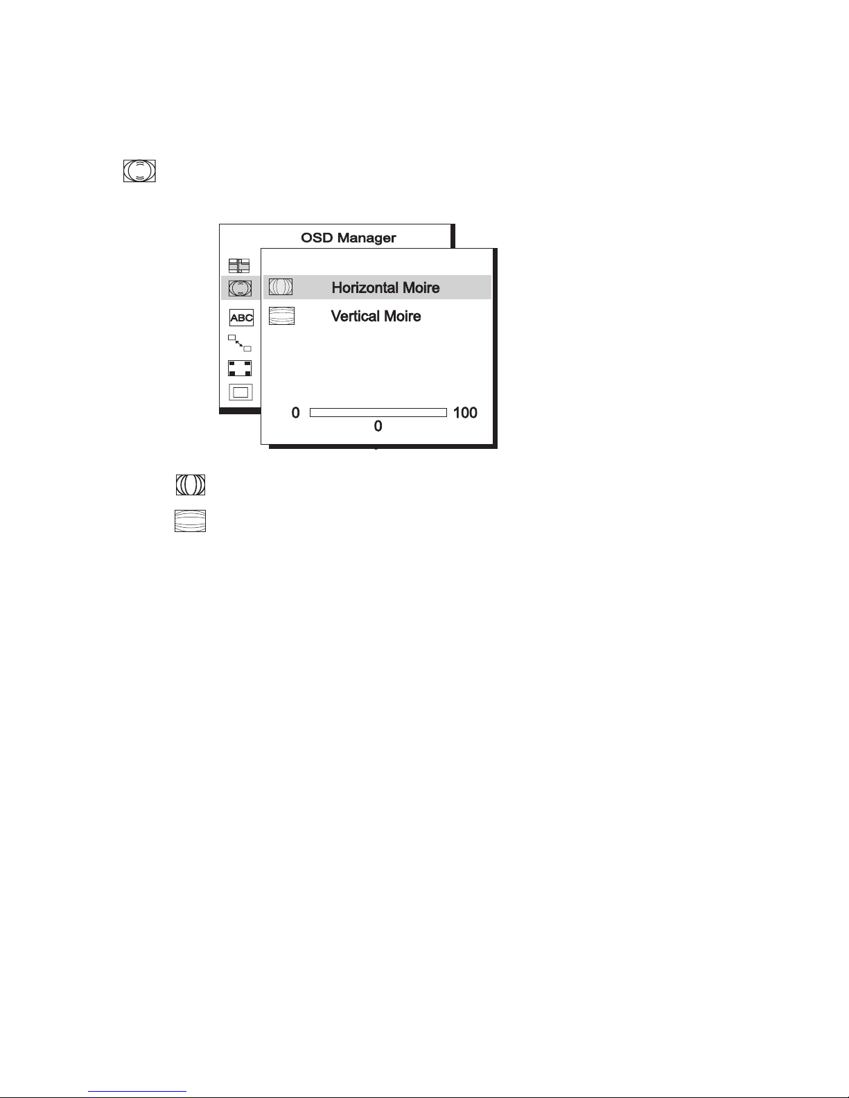
Moire
Horizontal & V ertical Moire adjustment
Horizontal Moire: adjusts horizontal Moire
V ertical Moire: adjusts vertical Moire
Moire refers to an i nterference pa ttern of dark w avy lines on the scree n. It is an
interference phenomenon caused by the relationship between the phosphor layout and the imaging signal. I n fact, it is often considered an indication of good
focus level .
? It is especially noticeable when using a light-gray or every-other-
dot pattern. Moire cannot be elimina t ed. Howeve r, it ca n be re-
duced with the moire reductio n feature.
Moire can be reduced by using the moire reduction function. Prior to adjustment,
display a full white pattern so that any moire will be visible. Display a different
screen background to check the effect after making the adjustment.
? If t he pict ure is unsta ble when you adjust the moir e reduction
setting, over-adjustment has occured. Please lower the moire re-
duction setting level. (Factory default setting value : 0).
Page 23
18
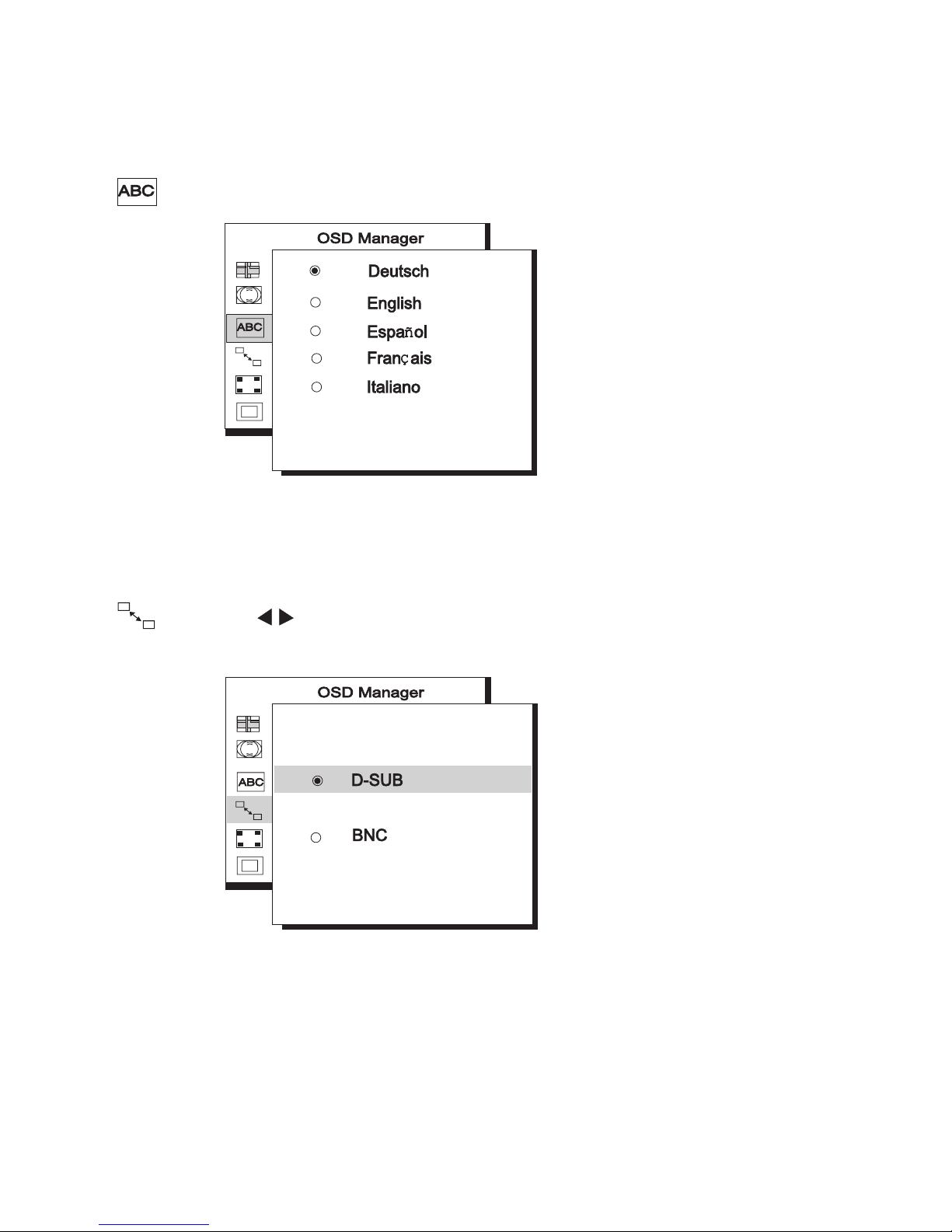
Language Select
The sub-menu is defined as language selection and there are five lan-
guages to choose from.
D-Sub BNC
Input connector select.
The Diamond View 21 15E monitor has two types of signal input connector , BNC
connector and VGA-type (15 pin D-Sub). The 2115E monitor will auto matically
detect the type of connector that a signal is connected to. If the two connectors
are connected simultaneously, use this adjustment to select the signal that is
to be displayed.
Page 24
19
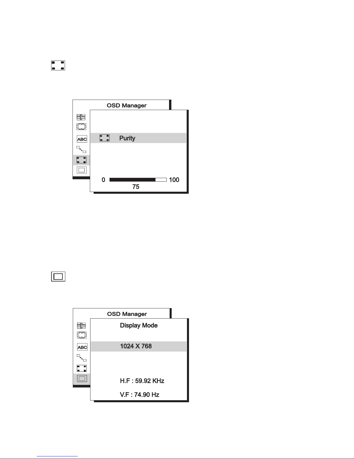
Purity
Colour purity adjustment
The purity adjustment is provided to correct for changes in the colour
displayed on the monitor that can be caused by the earth's magnetic field or
local magnetic fields. For best results, display a white image covering the entire
display when changing the purity setting.
Display Mode
Current resolution, horizontal and vertical frequency status presentation.
Page 25

20
Most computers allow you to make adjustments to the graphics adaptor settings that set the resolution, signal timing and refresh rate. The Diamond View
21 15E can accept a graphics signal that has a vertical frequency (refresh rate)
between 50 Hz and 160 Hz and an horizontal frequency between 30 KHz to 1 15
KHz. To avoid possible damage to the monitor , it is important that the graphics
singal that is displayed does not exceed the vertical refresh rates shown in the
table below.
Resolution Recommended Maximum Vertical
Refresh Rate(Hz)
640 x 480 160
800 x 600 160
1024 x 768 143
1280 x 1024 108
1600 x 1200 92
1920 x 1440 77
? To set the timing and the refresh rate, please see the user's guide of
your video card.
Timing Setting
Page 26
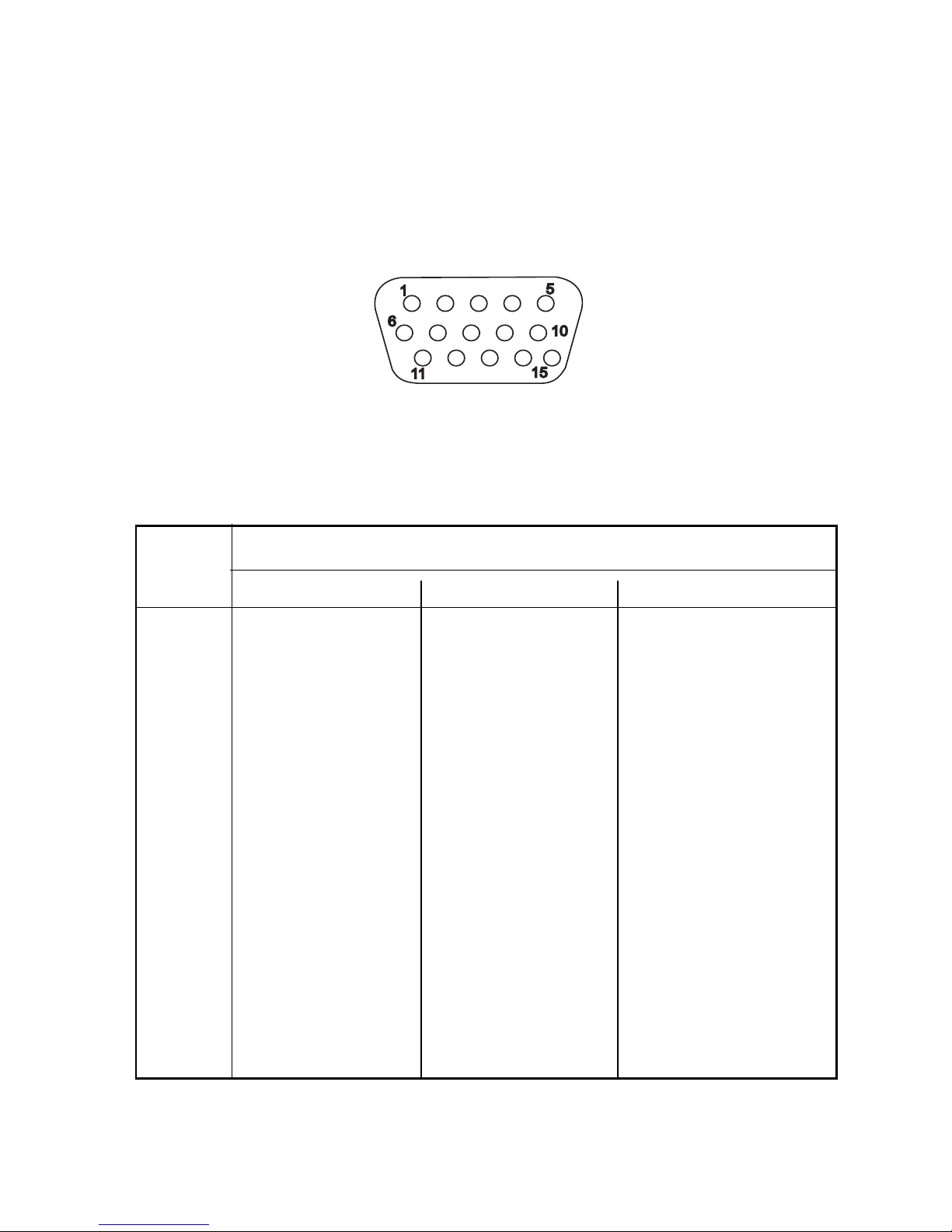
21
Signal
Pin No Separate Composite Sync-on-green
1 Red Red Red
2 Green Green Green + SYNC
3 Blue Blue Blue
4 NC NC NC
5 GND GND GND
6 R-GND R-GND R-GND
7 G-GND G-GND G-GND
8 B-GND B-GND B-GND
9 PC5V(For DDC) PC5V(For DDC) PC5V(For DDC)
1 0 GND-SYNC GND-SYNC GND-SYNC
11 GND GND GND
12 DDC Data DDC Data DDC Data
13 H-SYNC H/V-SYNC Not Used
14 V-SYNC Not Used Not Used
15 DDC Clock DDC Clock DDC Clock
Pin Assignments
D-SUB Connectors
Page 27
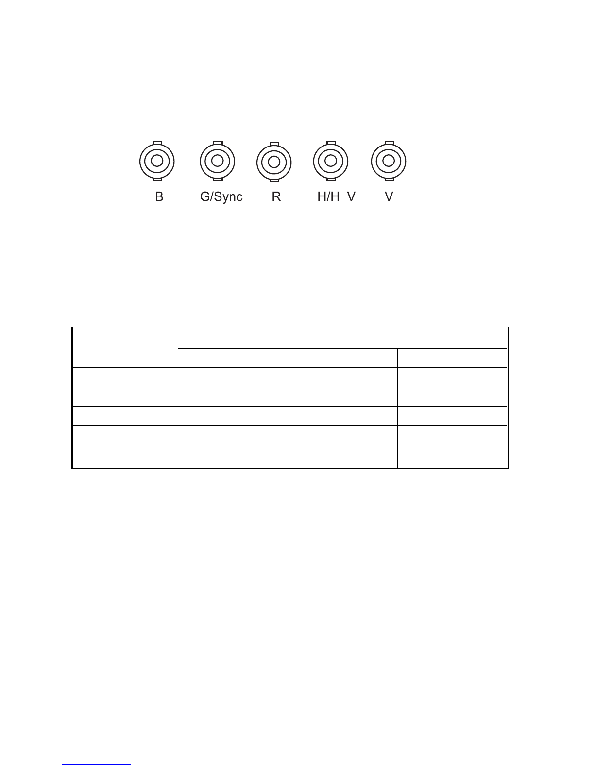
22
Pin Signal
Assignment separate composite sync-on-green
B Blue Blue Blue
G/SYNC Green Green Green + SYNC
R Red Red Red
H/H+V H-SYNC H/V-SYNC NC
V V-SYNC NC NC
BNC Connectors
Page 28

23
4 Troubleshooting
If you encounter any trouble in using this product, please make sure that
your monitor is properly installed and that the signal and power cables are securely connected. See Chapter 2, Installing the Monitor. If the problems
persist, check this chapter for possible solutions. Windows drivers for the Diamond View 2115E monitor are available from the File Downloads section at
Mitsubishi Electric Australia’s web site: www.mitsubishi-electric.com.au.
§ There is no picture on the screen.
Check:
❑ Video sync signal. The video sync signal from the graphics card must be
as specified for the monitor.
❑ Power saving mode. Press any key and move the mouse to deactivate
the mode.
❑ Signal cable connector pins. If there are bent or missing pins, consult
your place of purchase.
§ The picture is scrolling or unstable.
Check:
❑ Signal cable connectors and pins. Replace the signal cable if it is damaged.
❑ Graphics card. See if the settings are correct and within the monitor’s
specifications.
❑ Scanning frequencies. Change the settings of your graphics card to val-
ues within the monitor’s range .
❑ Remove any magnetic objects that are near the monitor. These include
speakers and power supplies ( AC Adaptors ).
Page 29

24
§ Characters look dark; the picture is too small or too large, not centered, etc.
❑ Adjust related settings. See Chapter 3, Adjusting the Monitor.
§ Colours are impure.
❑ Check the signal cable and connector pins. If there are bent or missing
pins, consult your place of purchase.
❑ Adjust related settings. See Chapter 3, Adjusting the Monitor.
Page 30

25
Need More Help?
If your problems remain after checking this manual, please contact your place of
purchase or contact:
Australia
Visit the Mitsubishi Electric Australia web site at
www.mitsubishi-electric.com.au
Or contact the Service Department for your state:
Victoria and Tasmania
4 / 303 Burwood Hwy
East Burwood, 3151
Tel: (03)9262-9899
Fax: (03)9262-9850
New South Wales and Australian
Capital Territory
348 Victoria Road
Rydalmere, 21 16
Tel: (02)9684-7669
Fax: (02)9684-7684
Queensland
1 / 104 Newmarket Road
Windsor, 4030
Tel: (07)3357-8877
Fax: (07)3357-8488
Western Australia
5 / 329 Collier Road
Bassendean, 6054
Tel: (08)9377-341 1
Fax: (08)9377-3499
South Australia and Northern
Territory
77 Port Road
Hindmarsh, 5007
Tel: (08)8340-0444
Fax: (08)8340-0555
New Zealand
Contact Melco New Zealand Ltd.
1 Parliament St.
Lower Hutt
Tel: (04)560-9100
Fax: (04)560-9140
Web site: www.melco.co.nz
Page 31
26
Picture
Size 21” (53.34 cm) diagonal
Dot Pitch 0.25 mm dot pitch
Surface/Transmission AR, AS/semi-tinted
Maximum Viewable Size 20” (51 cm) diagonal
Video Input 15-pin, mini D-SUB Connector/ BNC Connector
Bandwidth 297 MHz
Display Area 390 mm (H) x 295 mm (V) (Preset)
408 mm (H) x 306 mm (V) (Full Scan)
Power Supply(Universal)
Input voltage 100~240 VAC, 50~60 Hz
(Universal compatible)
Power consumption 150 Watts max.
External Controls Power switch, Auto-calibration, Contrast,
Brightness, Horizontal Position,
Horizontal Size, Vertical Position,
Vertical Size, Pincushion, Unbalance,
Trapezoid, Parallelogram, Rotation,
Top Corner, Bottom Corner,Color Weight,
Degaussing, Horizontal Convergence,
Vertical Convergence, Horizontal Moire,
Vertical Moire, BNC and DB-15 Selection,
Reset, Language Select, Purity
5 Specifications
Page 32
27
Max. Resolution 1920 x 1440 pixels
Horizontal Frequency 30-115 KHz
Vertical Frequency 50-160 Hz
Dimensions (with stand) 508 mm (W) x 515 mm (H) x 512 mm (D)
Weight 30 Kg
Ambient Temperature
Operating +5 °C ~ +40 °C
Storage -20 °C ~ +60 °C
Humidity
Operating 20% ~ 90%
Storage 10% ~ 90%
X-Radiation DHHS, PTB
Regulatory Compliance AS/ NZS 60950, EN 60950, UL, TÜV-GS,
AS/NZS 3548 (C-Tick), TÜV-Ergo, MPR II
 Loading...