

Diamond Power Products GNSF35Z01, GNSF18Z01, GXSF39B, GXSF27B User Manual

GNSF18Z01
GNSF35Z01
GXSF27B
GXSF39B
GE Appliances
215C1044P014 49-50049 04–00 JR 7220986
www.geappliances.com
Water Softening
system
Safety Instructions
Proper installation . . . . . . . . . . . .3
Installation Instructions
Drain connections . . . . . . . . . .7, 8
Important recommedations . . . .4
Installation instructions . . . . . .4-6
Planning and location . . . . . . . . .5
Programming the control . . . . . .9
Sanitizing . . . . . . . . . . . . . . . . . .10
Specifications and
dimensions . . . . . . . . . . . . . . . . .11
Step-by-step instructions . . .7–11
Tools and materials required . .5
Unpacking and inspection . . . . .4
Operating Instructions, Tips
Breaking a salt bridge . . . . . . . .13
Cleaning the nozzle and
venturi assembly . . . . . . . . . . . .14
Control displays . . . . . . . . . . . . .15
Electronic diagnostics . . . . . . . .17
Features . . . . . . . . . . . . . . . .15, 16
Regenerating the system . . . . .18
Service . . . . . . . . . . . . . . . . . . . . .12
Water softener system . . . . .12-18
Care and Cleaning
Salt storage level and
refilling . . . . . . . . . . . . . . . . . . . .19
Cleaning out iron . . . . . . . . . . .19
Troubleshooting Tips . . .20–22
Consumer Services
Appliance registration . . . .25, 26
Important phone
numbers . . . . . . . . . . .Back Cover
Parts list/catalog . . . . . . . . .27–30
Warranty . . . . . . . . . . . . . . . . . . .31
Owner’s Manual &
Installation Instructions
GE & You, A Service Partnership.
2
FOR YOUR RECORDS
Write the model and serial numbers here:
#
#
You can find them on the back of the control head.
Staple sales slip or cancelled check here.
Proof of the original purchase date is needed to obtain service under the warranty.
Inside you will find many helpful hints on how to use and maintain your water system properly. Just a little
preventive care on your part can save you a great deal of time and money over the life of your system.
READ THIS MANUAL
IF YOU NEED SERVICE
You’ll find many answers to common problems in the
Before You Call For Service
section. If you review our chart of
Troubleshooting Tips
first, you may not need to call for service at all.
If you do need service, you can relax knowing help is only a phone call away. A list of toll-free customer service
numbers is included in the back section of this manual. Or, you can always call the GE Answer Center® at
800.626.2000, 24 hours a day, 7 days a week.
OR
Visit our Website at:
geappliances.com
IMPORTANT!
Fill out the Consumer Product Registration Card.
Two easy ways to register your appliance!
■ Through the internet at www.geappliances.com
■ Complete and mail the enclosed Product Registration Card

3
IMPORTANT SAFETY INFORMATION.
READ ALL INSTRUCTIONS BEFORE USING.
WARNING!
For your safety, the information in this manual must be followed to minimize the risk of
electric shock, property damage or personal injury.
SAFETY PRECAUTIONS
■ Check and comply with your state and local codes.
You must follow these guidelines.
■Use care when handling the water softening system.
Do not turn upside down, drop, drag, or set on sharp
protrusions.
■Water softening systems using sodium chloride (salt)
for regeneration add sodium to the water.
Persons on
sodium restricted diets should consider the added sodium
as part of their overall intake. Potassium chloride can be
used as an alternative to sodium chloride.
■
The water softening system works on 24 volt-60 Hz
electrical power only.
Be sure to use only the included
transformer.
■Keep the salt hole cover in place on the softener
unless servicing the unit or refilling with salt.
WARNING:
Do not
use with water that is
microbiologically unsafe or of unknown quality
without adequate disinfection before or after the
system.
READ AND FOLLOW THIS SAFETY INFORMATION CAREFULLY.
SAVE THESE INSTRUCTIONS
PROPER INSTALLATION
■Install or store where it will not be exposed to
temperatures below freezing or exposed to any type
of weather. Water freezing in the system will break it.
Do not attempt to treat water over 100°F.
■
Do not
install in direct sunlight. Excessive sun
heat may cause distortion or other damage to
non-metallic parts.
■Properly ground to conform with all governing
codes and ordinances.
■Use only
lead-free solder and flux
for all sweat-solder
connections, as required by state and federal codes.
■
The water softening system requires a minimum water
flow of three gallons per minute at the inlet. Maximum
allowable inlet water pressure is 125 psi. If daytime
pressure is over 80 psi, nighttime pressure may exceed
the maximum. Use a pressure reducing valve to reduce
the flow if necessary.
■
Softener resins may degrade in the presence of
chlorine above 1 ppm. If you have chlorine in excess
of this amount, you may experience less life of the
resin. In these conditions, you may wish to consider
purchasing a GE point-of-entry household filtration
system with a chlorine reducing filter. Contact the
GE Answer Center at 1-800-626-2000 for more
information.
WARNING:
Discard all unused parts and packaging
material after installation. Small parts remaining
after the installation could be a choke hazard.
This water softening system must be properly installed and located in accordance with the Installation
Instructions before it is used.

Read entire manual. Failure to follow all guidelines and rules could cause personal injury or property damage.
• Before you begin installation, read these Installation Instructions completely. Then, obtain all the materials
and tools you will need to make the installation. Failure to properly install the softener voids the warranty.
• Check local codes. The installation must conform to them.
• In the Commonwealth of Massachusetts, Plumbing Code 248 CMR shall be adhered to. Consult with your
licensed plumber.
• Use only lead-free solder and flux for all sweat-solder connections, as required by state and federal codes.
• Connect the softener to the main water supply pipe
before
or
ahead of the
water heater.
DO NOT RUN
HOT WATER THROUGH THE SOFTENER.
Temperature of water passing through the softener must be less
than 120° F.
• Use care when handling the softener. Do not turn upside down, drop, drag, or set on sharp protrusions.
• Maximum allowable inlet water pressure is 125 psi. If daytime pressure is over 80 psi, nighttime pressure may
exceed the maximum. Use a pressure reducing valve if necessary. (Adding a pressure reducing valve may
reduce the flow.)
• The softener works on 24 volt-60 Hz electrical power only. Be sure to use the included transformer. Be sure
the electric outlet and transformer are in an inside location to protect from wet weather.
• See
Where to Install the Softener
section for more details.
WARNING:
Do not use with water that is microbiologically unsafe or of unknown quality without
adequate disinfection before or after the system. The water should be tested periodically to verify that the
system is performing satisfactorily.
Small parts remaining after the installation could be a choke hazard. Discard safely.
4
Installation instructions.
CAUTION:
Certain plumbing skills are needed for installation. If you are unsure about any part of the
installation of this product, consult a professional plumber.
Unpacking and Inspection
Be sure to check the entire softener for any shipping damage or parts loss. Also note damage to the
shipping cartons. Contact the transportation company for all damage and loss claims. The manufacturer is not
responsible for damages in transit.
Small parts, needed to install the softener, are on a skin-packed cardboard piece. To avoid loss of the small
parts, keep them on the skin-pack until you are ready to use them.
Important Installation Recommendations

5
• Place the softener as close as possible to a sewer drain, or other acceptable drain point or standpipe.
• It is recommended to keep outside faucets on hard water to save soft water and salt.
• Do not install the softener in a place where it could freeze.
Freeze damage is not covered by the warranty.
• Do not install the softener where it would block access to the water heater or access to the main water shutoff.
• Put the softener in a place where water damage is least likely to occur if a leak develops. The manufacturer
will not repair or pay for water damage.
• A 120 volt electric outlet is needed to plug in the included transformer. The softener has a 10 foot power
cable. If the outlet is remote (up to 100 feet), use 18 gauge wire to connect.
Be sure the electric outlet and
transformer are in an inside location, to protect from wet weather.
Be sure the outlet
is unswitched to prevent accidental shutoff.
• If installing in an outside location, you must take the steps necessary to assure the softener, installation
plumbing, wiring, etc., are as well protected from the elements (sunlight, rain, wind, heat, cold),
contamination, vandalism, etc., as when installed indoors.
•
Keep the softener out of direct sunlight.
The sun’s heat may distort non-metallic parts and may damage the
electronics.
Where to Install the Softener
• In and out fittings included with the softener are
3
⁄4″(nominal) copper sweat tubes. To maintain full valve
flow, 1″pipes to and from the softener fittings are recommended. You should maintain the same, or larger,
pipe size as the water supply pipe, up to the softener inlet and outlet.
• Use the included bypass valve to install the softener. The bypass valve allows you to turn off water to the
softener for servicing, but still have water in the house pipes. The in and out fittings referred to above connect
to the bypass valve with the included nuts and washers.
• Use copper, brass or galvanized pipe and fittings. Some codes may also allow CPVC plastic pipes.
• If additional drain hose is needed for valve and salt tank drains, it can be ordered from GE Parts at
800.626.2002.
• If a rigid valve drain is needed to comply with plumbing codes, you can buy the parts needed to connect a
1/2″copper tubing or plastic pipe drain.
• Clean nugget or pellet water softener salt is needed to fill the brine tank, see
Step 8
in the
Step-by-Step
Installation Instructions.
Tools and Materials Required for Installation
You must first decide how to run in and out pipes to the softener. Look at the house main water pipe at the
point where you will connect the softener. Is the pipe soldered copper, glued plastic, or threaded galvanized?
What is the pipe size?
WARNING:
Use only lead-free solder and flux to prevent lead poisoning.
See
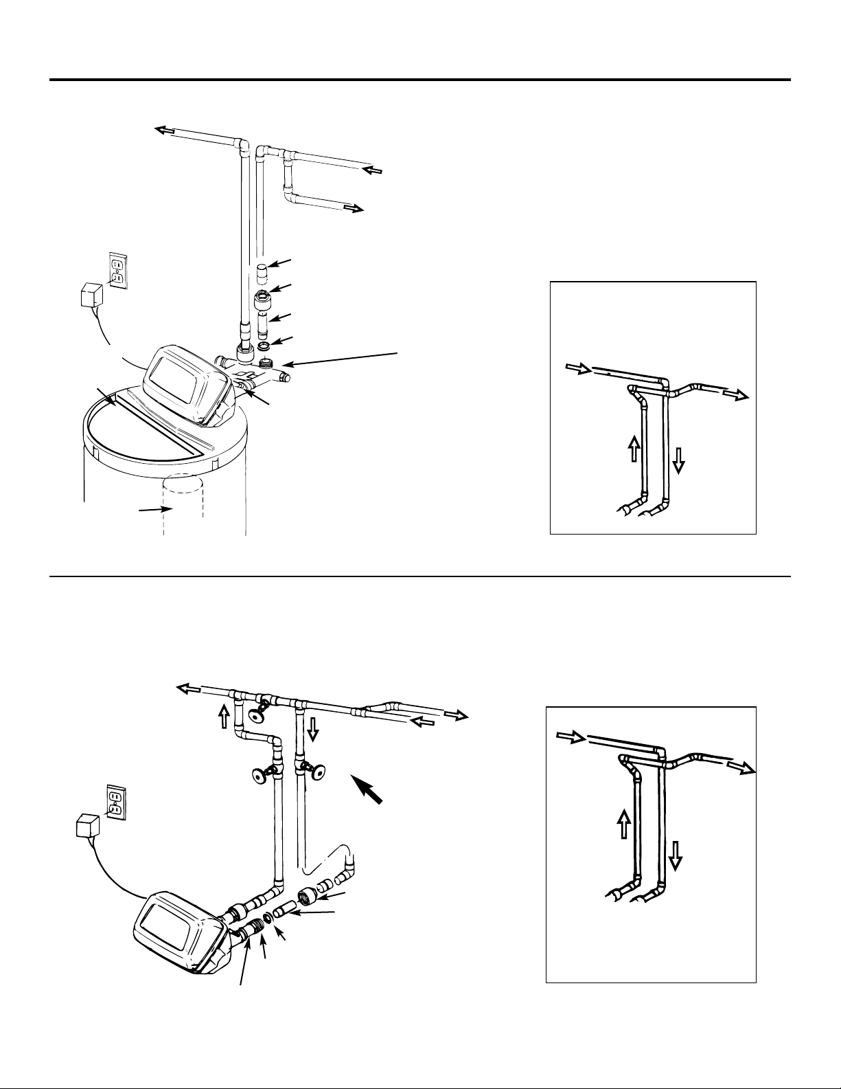
Typical Installation Illustration,
Fig.1. Use this as a guide when planning your particular installation.
Be sure to
direct the incoming hard water supply to the softener valve inlet fitting.
The valve is marked INand
OUT.
See below
to help you prepare.
Plan How You Will Install the Softener
Installation instructions.
Typical Installation Illustration
Optional 3-Valve Bypass Installation Illustration
6
Soft water
Hard water to
outside faucets
MAIN WATER PIPE
Hard water
NOTE:
See
Drain Hose
Connections
section.
24V transformer
120-volt outlet
Hard water
Soft water
From softener
outlet
To softener
inlet
Hard water
Soft water
From softener
outlet
To softener
inlet
CROSS-OVER
Use if water supply flows from the left.
Include single or 3-valve bypass.
MAIN WATER PIPE
Soft water
Hard water
24V transformer
120-volt outlet
Bypass valve
Hard water to
outside faucets
Inlet valve
Outlet valve
3-valve bypass system
For soft water service:
• Open the inlet and outlet
valves
• Close the bypass valve
For bypass hard water:
• Close the inlet and outlet
valves
• Open the bypass valve
Salt hole
cover
removed
SALT
GOES HERE
Brinewell
INLET
Washer (2)
Copper tube, 3/4″ (2)
Installation nut (2)
Bypass Valve
• Pull out for service
• Push in for bypass
NOTE:
Threads on the bypass
valve are 1″male pipe. If 1″
pipes are needed, do not use
the copper tubes and nuts
included. Buy 1″pipe thread
female adapter, and plumb
directly to 1″threads.
Adapters for this installation are not supplied with the softener.
To order these adapters, call GE Parts 800-626-2000. (Ask for Part # WS60X10006.)
Nut (2)
Copper
tube,
3/4″(2)
Washer (2)
Installation adapter (2) (see above)
INLET
NOTE:
Threads on the installation adapters are 1″
male pipe. If 1″pipes are needed, do not use the
copper tubes and nuts included. Buy 1″ pipe thread
female adapter and plumb directly to 1″ threads on
installation adapters.
CROSS-OVER
Use if water supply flows from
the left. Include single or
3-valve bypass.
Fig. 1
Fig. 2
Union (not supplied) (2)
Step-by-step installation instructions.
• Turn off the gas or electric supply to the water heater, in the possibility that the
water heater may be drained while draining pipes.
• Turn off the water supply to pipes to be cut and drain the house water pipes.
• Open both hot and cold faucets.
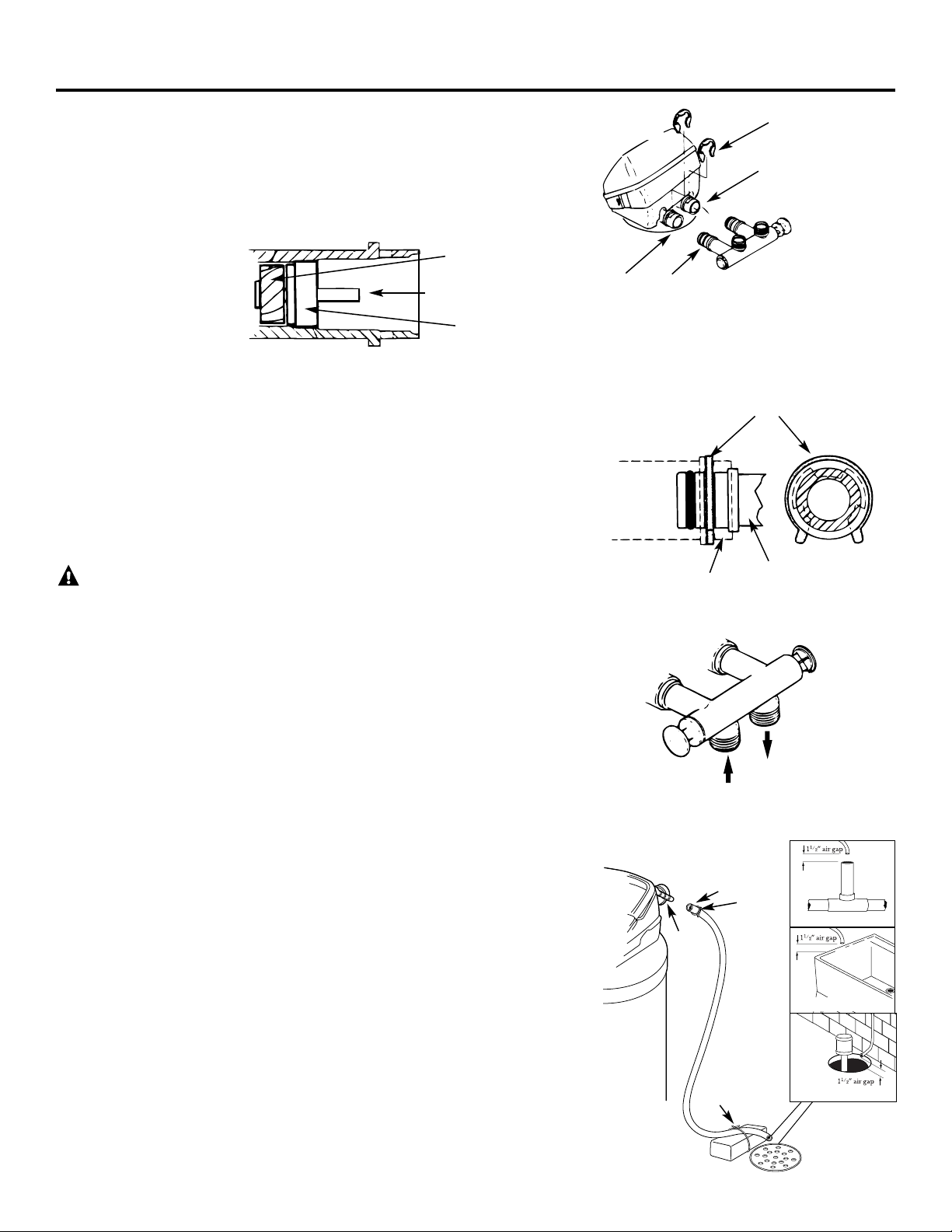
1. INSTALL BYPASS VALVE
• Remove plastic shipping plug and wire from valve outlet.
• Push the bypass valve (lubricate o-ring seals with silicone grease) into both ports
of the valve as shown in Fig. 3A.
• Snap the 2 large plastic clips in place, from the top, down as shown in Figures 3A
and 3B. Be sure they snap into place. Pull on the bypass valve to make sure it is
held securely in place.
2. MOVE THE SOFTENER ASSEMBLY INTO INSTALLATION POSITION:
• Be sure the installation surface is level and smooth. Sharp objects under the tank
may puncture it. If needed, place the tank on a section of 3/4″thick (minimum)
plywood. Then, place shims under the plywood as needed to level the softener.
3. PLUMB IN AND OUT PIPES TO AND FROM SOFTENER:
CAUTION: Observe all of the following cautions as you connect inlet and
outlet plumbing. See Fig. 1 or 2.
• BE SURE INCOMING HARD WATER SUPPLY IS DIRECTED TO THE
SOFTENER VALVE INLET PORT. If house water flow is from the left, use a
plumbing cross-over as shown in Fig. 1.
• If making a soldered copper installation, do all sweat soldering before connecting
pipes to the bypass valve. Torch heat will damage plastic parts.
• When turning threaded pipe fittings onto plastic fittings, use care not to
cross-thread.
• Use pipe joint compound on all external pipe threads.
• Support inlet and outlet plumbing in some manner (use pipe hangers) to keep
the weight off of the valve fittings.
4. CONNECT AND RUN THE VALVE DRAIN HOSE:
• Use the provided drain hose (20′length included) to attach to the valve drain
fitting. To keep water pressure from blowing the hose off, use a hose clamp to
secure in place.
• Locate the other end of the hose at a suitable drain point (floor drain, sump,
laundry tub, etc.) that terminates at the sewer. Check and comply with local codes.
IMPORTANT: If more drain hose is needed, it should be ordered from GE Parts
at 800.626.2002. The water softener will not work if water cannot exit this hose
during regenerations.
• Tie or wire the hose in place at the drain point. High water pressure will cause it to
whip during the back-wash and fast rinse cycles of regeneration. Also provide an
air gap of at least 1–1/2″between the end of the hose and the drain point. An air
gap prevents possible siphoning of sewer water into the softener, if the sewer
should “back-up.”
• If raising the drain hose overhead is required to get to the drain point, do not
raise higher than 8′above the floor. Elevating the hose may cause a back-pressure
that could reduce brine draw during regenerations.
Fig. 3A
Fig. 3B
Fig. 3C
Fig. 4
NOTE: Be sure the turbine
and support are firmly in
place in the valve outlet.
Blow into the valve port
and observe the turbine
for free rotation.
Drain
fitting
on
valve
Valve
drain
hose
FLOOR DRAIN
Turbine
Valve outlet
Turbine shaft
and support
IN
OUT
Turn bypass valve
upside down to
connect to floor
level plumbing
Valve body inlet or
outlet
Bypass valve
(push all the way in)
Clip
END
VIEW
Clip
Outlet
Inlet
O-ring seal goes into
the outer groove only.
The clip snaps into the
inner groove (see
below).
Bypass valve
NOTE:
Threads on the
bypass valve are 1″male
pipe. If 1″pipes are needed,
do not use the copper tubes
and nuts included. Buy 1″
pipe thread female adapter,
and plumb directly to 1″
threads.
SIDE
VIEW
Tie or wire hose
in place
1
1
⁄2″air gap
STANDPIPE
LAUNDRY TUB
SUMP
7
Clamp
Step-by-step installation instructions.
8
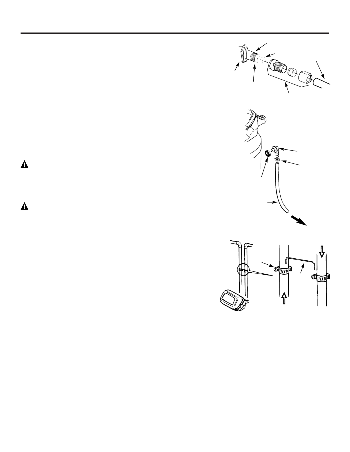
4A. CONNECTING A RIGID VALVE DRAIN TUBE
• To adapt a copper drain tube to the softener, use a hacksaw to cut the barbed end
from the drain fitting as shown in Fig. 4A. Rotate the drain fitting so the cutting
blade clears the valve housing to prevent damage to valve. Buy a compression fitting
(1/4″female pipe thread x 1/2″O.D. tube) and needed tubing from your local
hardware store.
5. INSTALL THE BRINE TANK OVERFLOW FITTINGS AND HOSE
• Insert the rubber grommet into the 3/4″ diameter hole in the brine tank sidewall
as shown in Fig. 5.
• Push the end of the hose adapter elbow into the grommet as shown in Fig. 5.
• Attach a length of hose (use remaining hose from Step 4) to the hose adapter
elbow.Use a hose clamp to hold it in place.
• Locate the other end of the hose at the drain point. DO NOT ELEVATE this hose
higher than the elbow on the brine tank.
IMPORTANT: DO NOT TEE OVERFLOW HOSE TO VALVE DRAIN HOSE.
NOTE: This drain is for safety only. If the cabinet (brine tank) should over-fill with
water, the excess is carried to the drain.
6. INSTALL GROUNDING CLAMPS AND WIRE
DANGER: Failure to properly attach ground wire could result in electrical shock.
• If plumbing is metal, to maintain electrical ground continuity in the house cold
water piping, install the included ground clamps as shown in Fig. 6. Be sure the
pipes are clean under the clamps to assure good contact.
7. FLUSH PIPES, EXPEL AIR FROM SOFTENER, AND TEST YOUR
INSTALLATION FOR WATER LEAKS:
CAUTION: To avoid water or air pressure damage to softener inner parts,
be sure to do the following steps in exact order.
A. Fully open 2 cold soft water faucets nearby the softener.
B. Place bypass valve in “bypass” position by pushing the stem inward.
C. Fully open the house main water pipe shutoff valve. Observe a steady flow from
both faucets opened in step A, above.
D. Place bypass valve in the “service” position EXACTLY as follows. KEEP SOFT
WATER FAUCETS OPEN.
SLOWLY pull or slide the valve stem (out) toward “service,” pausing several times
to allow the softener to pressurize slowly.
E. After about 3 minutes, open a HOT water faucet for 1 minute, or until all air
is expelled, then close. NOTE: If water appears cloudy or has salty taste, allow to
run for several more minutes, or until clear.
F. Close all water faucets.
G. Check your plumbing work for leaks and fix right away if any are found.
Be sure to observe previous caution notes.
H. Turn on the gas or electric supply to the water heater. Light the pilot, if applicable.
Fig. 4A
Fig. 5
Fig. 6
Clamp (2)
Ground
wire
From valve outlet
To valve inlet
To sewer
drain
Overflow drain hose
Hose clamp
Grommet
Clip
1/4″NPT threads
Barbs
1/2″O.D.
copper tube (not
furnished)
Cut barbs
from drain
fitting
Compression fitting, 1/4″
NPT X 1/2″O.D. tube (not
furnished)
Do not connect to valve
drain hose.
8. ADD WATER AND SALT TO THE BRINE TANK:
• Lift the cabinet (brine tank) cover. Add about 3 gallons of water into the tank. Do not add into the brinewell.
• Fill tank with NUGGET, PELLET or coarse SOLAR water softener salt with a purity of 99.5% or higher. Do not use rock, block,
granulated, and ice cream-making salts, or salt with iron-removing additives (except for Diamond Crystal® Red•Out® brand salt).
Salt storage capacity is approximately 140 lbs. for model GNSF18 and 200 lbs. for the other models. Keep the salt hole cover in
place on the softener unless servicing the unit or refilling with salt.
NOTE: If the softener is installed in a humid basement or other damp area, it is better to fill the tank with less salt, more frequently.
Eighty to 100 lbs. of salt will last for several months, depending on water hardness, family size and water softening system model.
9. CONNECT TO ELECTRICAL POWER:
• If transformer wiring is not visible at the back of the control head, remove control cover. DO NOT PULL ON OR DISCONNECT
WIRING. Locate the long wire with “U” shaped connectors on one end. Route this wire through the rear of the control housing.
Replace the control cover.
• Fasten the 2 power cable lugs (“U” shaped connectors) to the 2 screws on the transformer, and tighten the screws. Then, plug the
transformer into the electrical outlet.
• The softener works on 24 volt-60Hz electric power. The included transformer changes standard 120 volt AC house power to
24 volts. Plug the transformer into a 120 volt outlet only. Be sure the outlet is always live so it can not be switched off by mistake.
10. PROGRAM THE CONTROL:
• See Programming the Control section.
Hose adapter
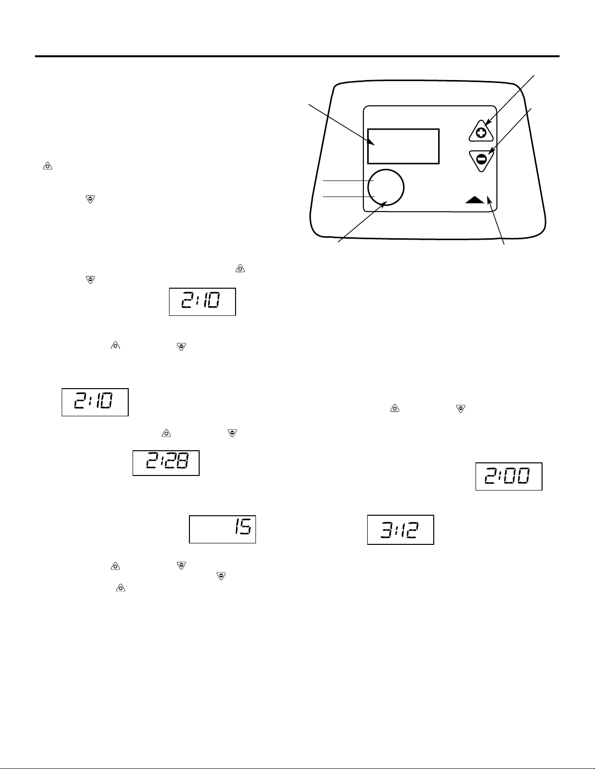
SET REGENERATION (STARTING) TIME
NOTE: RECHARGE TIME and a flashing 2:00 AM
(factory default) should show in the display. This is a good
time for regeneration to start (over in about 2 hours) in most
households because water is not in use. HARD WATER is
bypassed to house faucets during regeneration.
If no change is needed, go to step 2. To change the
regeneration starting time, follow step 1.
1. Press the UP
(+)
or DOWN (-) button to set the
desired regeneration start time.
NOTE: Each press of the buttons changes the time by 1 hour.
Holding the buttons in changes the time twice each second.
2. Press the SELECT button once more.
Be sure to observe the AM or PM, as
you did when setting the time of day.
The display shows the present time of day and RECHARGE
TONIGHT.
9
CONTROL SETTINGS REQUIRED upon installation and
after an extended power outage.
NOTES:
•
WHEN THE TRANSFORMER IS PLUGGED INTO THE
ELECTRICAL OUTLET (see step 9), 12:00 AM (flashing),
and PRESENT TIME show in the display area. Program the
control as instructed below. If SR - - is flashing, use the UP (+)
button to set the correct SR code as follows: SR18 for
GNSF18,
SR35 for GNSF35, SR31 for GXSF39, or SR22 for
GXSF27. If
you pass by the correct code number, use the
DOWN (-) button. Then press the SELECT button and
program the control.
•
A “beep” sounds while pressing buttons for control programming.
One beep signals a change in the control display. Repeated beeps
mean the control will not accept a change from the button you
have pressed, and you should use another button.
• To program the control, you will use the UP (+) ,
DOWN (-) and SELECT buttons.
SmartWater Softener System
TOUCH
or
HOLD
SELECT
TIME
HARDNESS
RECHARGE NOW
RECHARGE TONIGHT
Display
TOUCH or HOLD button
SELECT button
DOWN (-)
button
UP (+)
button
PRESENT TIME
PM
SET PRESENT TIME OF DAY
NOTE: If the words PRESENT TIME do not show in the display,
press the SELECT button until they do.
1. Press the UP (+) or DOWN (-) button to set. The UP
button moves the display ahead; the DOWN button moves the
time backward.
If the present time is between noon and midnight, be sure PM
shows .
NOTE: Each press of an UP (+) or DOWN (-) button changes
the time by one minute. Holding the button in changes the time
32 minutes each second .
2. When the present time shows, press SELECT to set. If the present
time is between midnight and noon, be sure AM shows.
SET WATER HARDNESS NUMBER
NOTE: If 15 (factory default) and
HARDNESS do not show in the
display, press SELECT until they do.
1. Press the UP (+) or DOWN (-) button to set your water
hardness number in the display. DOWN (-) moves the display
down to 1. UP (+) moves the maximum setting.
NOTE: Each press of a button changes the display by 1 between 1
and 25. Above 25, the display changes 5 at a time (25, 30, 35, etc.).
Holding a button in changes the numbers twice each second.
2. When your water hardness number shows, press SELECT to set.
NOTE: If there is clear water iron in your water supply, you will
need to increase the hardness setting by 5 for each 1 ppm of clear
water iron in your water supply.
You can get the grains per gallon (gpg) hardness of your water
supply from a water analysis laboratory, or call and ask your local
water department, if you are on a municipal supply, or call GE
Answer Center®to request a water hardness test kit. If your report
shows hardness in parts per million (ppm) simply divide by 17.1 to
get the equivalent number of grains per gallon.
HARDNESS
PRESENT TIME
AM
PRESENT TIME
PM
Programming the Control
RECHARGE
AM
TIME
PM
RECHARGE TONIGHT
Step-by-step installation instructions.
10
Sanitizing Procedures
To complete the installation, do the following sanitizing procedures.
Care is taken at the factory to keep your water softener clean and sanitary. Materials used to make the softener
will not infect or contaminate your water supply and will not cause bacteria to form or grow. However, during
shipping, storage, installing and operating, bacteria could get into the softener. For this reason, sanitizing as
follows is suggested when installing.
NOTE: Sanitizing is recommended by the Water Quality Association for disinfecting.
Be sure to complete all installation steps, including timer programming.
Pour about 3/4 oz. of common 5.25% household bleach (Clorox, Linco, Bo Peep, White Sail, Eagle, etc.)
into the
brinewell
. Refer to illustration on page 6.
IMPORTANT:
Press and hold for 3 seconds the faceplate
TOUCH/HOLD
button to start an immediate
regeneration.
Recharge Now
begins to flash in the display. The bleach is drawn into and through the
water softener
.
If after sanitization water from house faucet tastes salty or has a slight color, this is a preservative from the
resin tank. Turn on the cold soft water faucets and drain for a few minutes or until clear.
4
3
2
1
NOTE:
When the above sanitizing regeneration is over, your house
COLD
water supply is fully soft immediately.
However, your water heater is filled with hard water and as hot water is used, it will refill with soft water. When
all the hard water is replaced in the water heater, hot only and mixed hot and cold water will be fully soft. If you
want totally soft water immediately, after the above regeneration, drain the water heater until the water runs
cold.
WARNING:
If you do drain the water heater, use extreme care as the hot water could cause burns. Turn
the water heater off prior to draining.
 Loading...