

Page 1

Micronics C400
Pentium II
System Board Manual
Document Number: 06-00351-01, Rev. B01
August 1998
2880 Junction Avenue, San Jose, CA. 95134-19228
Page 2

Micronics C400 System Board Manual
2
Copyright Notices
Copyright 1998 Diamond Multimedia Systems Inc. The informa-
tion contained in the Micronics C400 PCI/ISA/AGP Pentium II system
board manual has been carefully checked and is believed to be accurate.
Diamond assumes no responsibility for any inaccuracies that may be
contained in this document. Diamond makes no commitments to
update or to keep the information in this manual at a current level when
changes are made to the product.
Diamond reserves the right to make changes to this document and/or
product at any time and without notice. All Rights Reserved. No part
of this document may be photocopied, reproduced, translated, or
reduced to any medium or machine form without prior, written
consent from Diamond Multimedia Systems Inc.
Portions of the Manual
Portions of this manual were copied (with permission) from Award
Software, Inc. All rights reserved.
Trademarks
IBM is a registered trademark of International Business Machines.
Microsoft and Windows are registered trademarks of Microsoft Corporation. Intel, PCI and AGP are registered trademarks of Intel
Corporation. All other product names mentioned herein are used for
identification purposes only and may be the trademarks of their
respective companies.
Page 3

Micronics C400 System Board Manual
1
Table of Contents
Introduction 5
Features 6
Software Compatibility 7
Contents Listing 7
Before You Begin 8
Chapter 1 - Quick Installation 9
Installing the Micronics C400 9
Chapter 2 - Configuring the Micronics C400 11
Static Electricity 11
Environment Considerations 11
Micronics C400 System Board 12
Jumper and Connector Settings 13
Chapter 3 - Installing the Micronics C400 17
Introduction 17
System Memory Support 17
Installing the Micronics C400 18
Tools Required 18
Equipment Required 18
System Memory 19
Adding Memory 19
Memory Configurations 20
CPU Installation 22
Installing the CPU Retention Mechanism 22
Installing a CPU 23
CPU Installation Overview 25
CPU Installation (Box version) 26
Installing DIMMs 27
Page 4

Micronics C400 System Board Manual
Removing DIMMs 27
Installing a PCI Peripheral Card 28
Installing an ISA Peripheral Card 29
Installing an AGP Peripheral Card 30
Chapter 4 - The BIOS Setup Utility 31
Configuration 31
Initial Bootup 31
Setup 31
Running the Setup Program 33
Standard CMOS Setup 34
BIOS Features Setup 36
Chipset Features Setup 40
Power Management Setup 43
PnP/PCI Configuration Setup 47
Load BIOS Defaults 49
Load Setup Defaults 49
Integrated Peripherals 50
Supervisor Password 53
User Password 53
IDE HDD Auto Detection 54
HDD Low Level Format 55
Save and Exit Setup 56
Exit Without Saving 56
Chapter 5 - Special Features 57
Intel’s 440BX AGPset 57
Accelerated Graphics Port (AGP) 57
SDRAM (Synchronous DRAM) 58
Wake On LAN 58
Ultra DMA/33 IDE 59
Universal Serial Bus (USB) 59
2
Page 5

Micronics C400 System Board Manual
Appendix A - Technical Information 61
Specifications 61
Environmental Specifications 63
Temperature Range 63
Relative Humidity 63
Battery Disposal 64
Support and Information Services 65
Technical Support 65
Appendix B - POST Codes 67
Appendix C - POST Messages 71
Appendix D - Updating the System BIOS 73
Appendix E - Warranties and Notices 75
Limited Warranty 75
Non-Warranty Service 76
FCC Statement 77
Glossary 78
Index 82
3
Page 6

Micronics C400 System Board Manual
4
List of Figures
Figure 1.1: Power-Up Screen 10
Figure 2.1: Micronics C400 System Board 12
Figure 2.2: Back Panel Connections 12
Figure 3.1: Installing a 168-Pin DIMM 27
Figure 3.2: Installing a PCI Peripheral Card 28
Figure 3.3: Installing an ISA Peripheral Card 29
Figure 3.4: Installing an AGP Peripheral Card 30
Figure 4.1: Power-Up Screen 32
Figure 4.2: Main CMOS Setup Screen 33
Figure 4.3: Standard CMOS Setup Screen 34
Figure 4.4: BIOS Features Setup Screen 36
Figure 4.5: Chipset Features Setup Screen 40
Figure 4.6: Power Management Screen 43
Figure 4.7: PnP/PCI Configuration Screen 47
Figure 4.8: Integrated Peripherals Screen 50
Figure 4.9: IDE HDD Auto Detection Screen 54
Figure 4.10: HDD Low Level Format Screen 55
List of Tables
Table 2.1: CPU Speed Selection 13
Table 2.2: Clear Password/Keylock/Power LED Settings 13
Table 2.3: Connector & Peripheral Connections 14
Table 3.1: Memory Configurations 20
Table A.1: Support and Information Services 66
Page 7

Micronics C400 System Board Manual
Introduction
Thank you for choosing the Micronics C400 system
board. The Micronics C400 is an advanced single processor solution for high-performance desktops and workstations.
Based on the highly acclaimed Intel 440BX AGPset,
Micronics C400 supports the next generation of the
Pentium II, which offers flexibility and the highest level
of performance. It features support for 100MHz Front
Side Bus (FSB) speeds and accepts PCI, ISA and AGP
expansion cards.
Rich with features, Micronics C400 provides Ultra DMA/
33 IDE hard drive protocol (up to 33MBytes/sec transfer
rate), PC-100 SDRAM memory support and optional microprocessor system hardware management support.
Diamond builds all products to exacting standards, using
the highest quality components available. We are proud
to provide this system board and believe you will be
pleased with your purchase.
5
Introduction
Page 8

Micronics C400 System Board Manual
6
Features
The Micronics C400 includes the following features:
▲ Single Intel Slot 1
for: -
Intel Celeron 233-333MHz (66MHz FSB)
Intel Pentium II 350-450MHz (100MHz FSB)
▲ Intel 440BX AGPset
Intel PIIX4e
▲ One AGP slot
Four 32-bit PCI slots
One shared PCI/ISA slot
One 16-bit ISA slot
▲ Bus Speed - 66 and 100MHz
▲ Three 3.3V unbuffered 64/72-bit 168-pin DIMM sockets
Maximum memory - 768MB for SDRAM (PC-100Mhz
supported)
ECC support via chipset
▲ Hardware Management - microprocessor system hardware
monitor w/ CPU and chassis fan temperature sensors
▲ Ultra DMA/33 IDE support
▲ Mini ATX form factor
Introduction
Page 9

Micronics C400 System Board Manual
7
Software Compatibility
The Micronics C400 system board has been thoroughly tested
for compatibility with a variety of operating systems and
environments, including:
▲ Microsoft -
DOS 6.2x
Windows 95
Windows 98
Windows NT 3.5x
Windows NT 4.0
▲ IBM -
OS/2 Warp 4.0
▲ SCO -
UNIXWare 2.1.1
Open Server 5.04
▲ Novell -
NetWare 3.12
NetWare 4.11 (IntranetWare)
Contents Listing
The standard package should contain the following items.
Check to make sure that all the items are included.
▲ Micronics C400 System Board
▲ Micronics C400 CD (includes this manual in Adobe
Acrobat format)
▲ Two device 34-pin floppy disk drive ribbon cable
▲ Two device 40-pin hard disk drive ribbon cable
▲ Pentium II CPU retention post set
Introduction
Page 10
Micronics C400 System Board Manual
8
Before You Begin
This manual will familiarize you with the features, installation and use of your Micronics C400. There are several
symbols and conventions used throughout this manual to
help draw your attention to a feature or to focus on important
information:
When you see the Magnifying Glass, it refers
to something you should take a closer look at
before proceeding further.
When you see the Exclamation Mark, it gives
important information on avoiding damage.
Common Names
AGP Accelerated Graphics Port
DIMM Dual Inline Memory Module
DRAM Dynamic Random Access Memory
ECC Error Checking and Correction
EDO Extended Data Out
IDE Integrated Drive Electronics
PCI Peripheral Component Interconnect
SDRAM Synchronous DRAM
SPD Serial Presence Detect
USB Universal Serial Bus
Introduction
Page 11

Micronics C400 System Board Manual
Chapter 1: Quick Installation
9
1
Chapter
Quick Installation
We know that many experienced people prefer to read as
little of the documentation as possible. If this sounds like
you, here’s the short form to get up and running quickly.
Installing the Micronics C400
1. Make backup copies of your installation and configuration diskettes.
2. Ground yourself to prevent damaging static discharge by using an anti-static wrist or ankle strap, or
touch a safely grounded metal object.
3. Remove the Micronics C400 from its packaging.
4. Configure and verify the system board’s jumper settings (refer to Jumper Settings in Chapter 2).
5. Install the CPU and the system memory. Be sure to
attach the Retention Mechanism as described in
Chapter 3.
6. Install the system board in the chassis and make all
necessary case connections.
7. Install any ISA, PCI and/or AGP add-on peripherals
(refer to Chapter 2 for the location of the slots).
8. Connect any optional devices.
9. Turn the computer on and press the <DEL> key
when you see the screen shown in Figure 1.1.
STATIC!
Before
handling the
Micronics
C400, be
properly
grounded
by using a
special wrist
or ankle
strap, or
touch a
safely
grounded
object.
Page 12
Micronics C400 System Board Manual
10
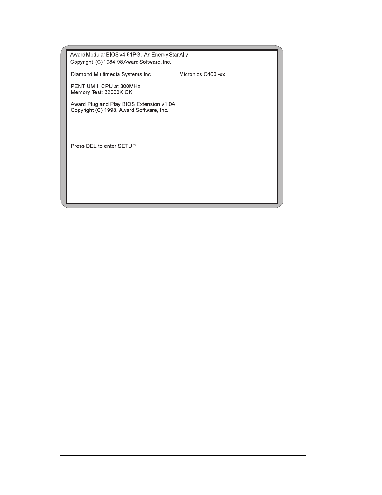
Figure 1.1: Power-Up Screen
Chapter 1: Quick Installation
10. The main CMOS Setup Utility screen (Figure 4-2)
appears. Note that the Setup program can only be
activated during the boot sequence.
11. Set the time and date. Adjust the BIOS settings to
match your configuration. If installing an IDE drive,
select the IDE device you wish to configure. Press
ENTER with Autotype Fixed Disk selected and the
BIOS will automatically configure the drive for you
(refer to Chapter 4).
12. After you have configured the Standard CMOS Setup
settings, make any desired setting configurations in
the other available menus. When finished, go to the
exit screen, select “Save and Exit Setup” and you are
finished with the BIOS configuration (see Chapter 4).
Page 13

Micronics C400 System Board Manual
Configuring the Micronic
s C400
Although the Micronics C400 system board is packaged
in materials that are designed to protect it from physical
damage and static electricity, it is important to use care
while unpacking the board and setting it up.
Static Electricity
The Micronics C400 is shipped from the factory in an
anti-static bag. To reduce the possibility of damage from
static discharge, it is important to neutralize any static
charges your body may have accumulated before handling the board.
The best way to do this is to ground yourself using a
special anti-static wrist or ankle strap. If you do not have
an anti-static strap available, touch both of your hands
to a safely grounded object, such as the power supply or
chassis of a computer that is connected to the power
socket. After you have grounded yourself, ground the
Micronics C400 board via one of the solder pads that
surround its mounting holes. When you remove the
Micronics C400 from its packaging, place it on top of the
anti-static bag, and carefully inspect the board for damage which might have occurred during shipment.
Environment Considerations
Make sure the finished computer system is in an area
with good ventilation. The system should not be in direct
sunlight, near heaters, or exposed to moisture, dust, or
dirt.
11
Chapter 2: Configuring the Micronics C400
2
Chapter
Page 14
Micronics C400 System Board Manual
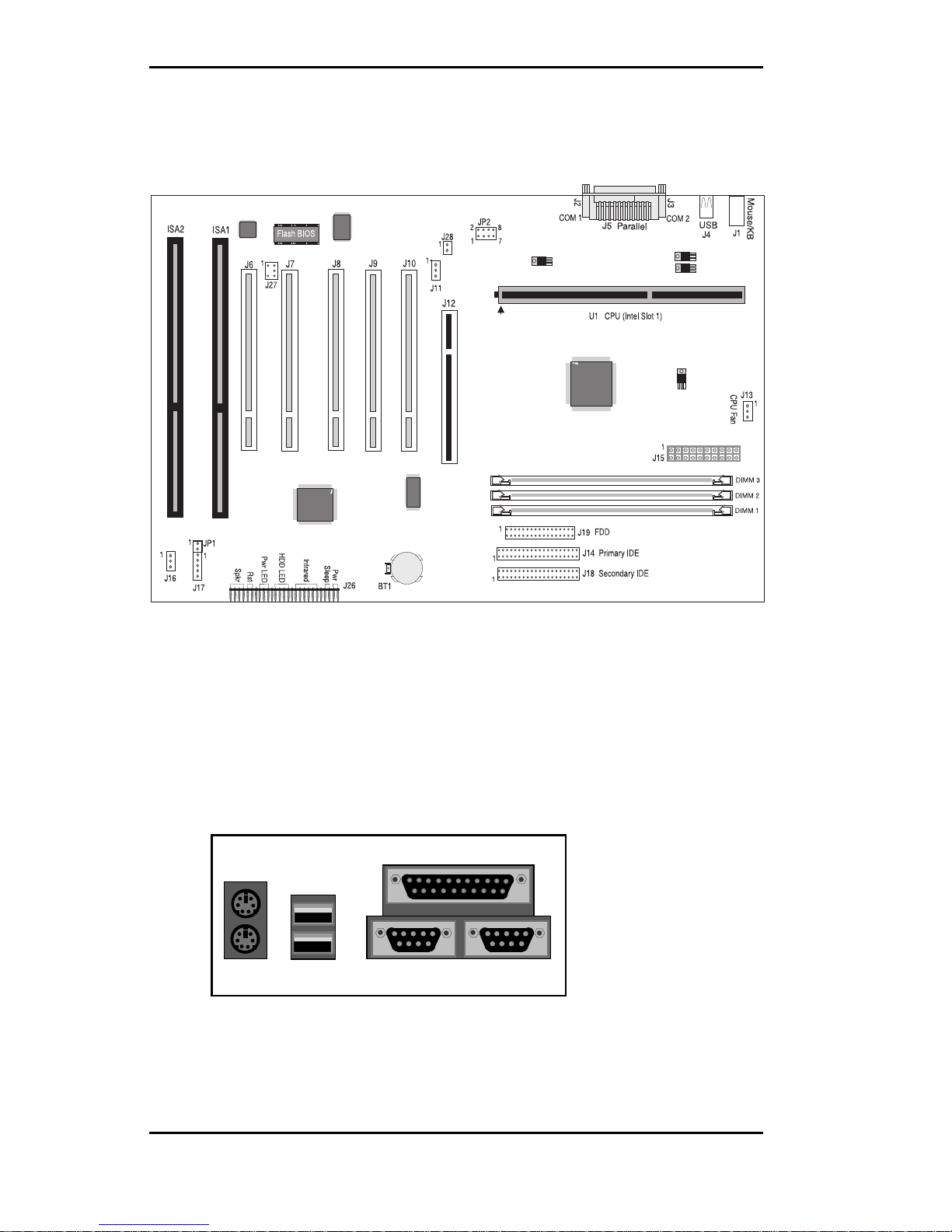
Micronics C400 System Board
Back Panel Connections
Chapter 2: Configuring the Micronics C400
12
Figure 2-1: Micronics C400 System Board Diagram
Figure 2-2: Back Panel Connections
(Intel Venus I/O Shield Compatible)
Parallel Port (Printer)
USB 1
USB 2
COM 1
COM 2
PS/2
Mouse
PS/2
Keyboard
Page 15
Micronics C400 System Board Manual
Chapter 2: Configuring the Micronics C400
13
Jumper and Connector Settings
This section provides jumper and connector settings for the Micronics
C400 system board that may or may not need to be changed. Other
configurations can be changed through the BIOS Setup.
Table 2-1 lists the jumper settings to select the CPU bus speed frequency.
Table 2-2 lists the settings for clearing a password, locking your case and
the power LED. To clear a password set in the BIOS, place a jumper on JP1.
The Power LED is the same as the Power LED in the Front Panel
connectors.
T ab le 2-1: CPU Speed Selection
2PJrepmuJ
metsyS
deepS
suB
deepS
2-14-36-58-7
332
zHM
zHM66nepO
esolC
nepOesolC
662
zHM
zHM66
esolC
nepO
esolC
esolC
03
zHM0
zHM66
esolC
nepOnepOesolC
333
zHM
zHM66nepOnepOesolCesolC
003
zHM
zHM001nepOesolCesolCesolC
53
zHM0
zHM001nepOesolCnepOesolC
004
zHM
zHM001
esolCnepO
esolCesolC
54
zHM0
zHM001esolCnepOnepOesolC
2
1
JP2
8
7
T ab le 2-2: Clear P ass word/Ke y Lock/P ower LED Settings
Clear
Password
LED -
N/A
LED +
Ground
Keylock
Keylock
Power
LED
JP1
J17
Page 16

Micronics C400 System Board Manual
Chapter 2: Configuring the Micronics C400
14
Table 2-3 lists the connector settings and their functions.
Table 2-3: Connector and Per ipheral Connections
rotcennoCnoitcnuFsetoN
3-1MMIDMMIDnip-861(MARD
)stekcoS
MARDSdnaODEdereffubnu,tlov3.3
sMMID
2-1ASIstolSnoisnapxEsuBASI
1JrotcennoCdraobyeK2/SP
rotcennoCesuoM2/SP
leveLrewoL
leveLreppU
3J,2JstroPlaireS2MOC&1MOC
4JrotcennoCBSU1troPBSU:leveLrewoL
2troPBSU:leveLreppU
5JrotcennoCtroPlellaraPleveLreppU
01J-6JstolSnoisnapxEsuBICP
11JrotcennoCNALnOekaW-2;tuptuOrewoPybdnatSV5+-1
tupnIlangiSpuekaWNAL-3;dnuorG
21JtolSnoisnapxEsuBPGArotcennocnip-2x26
31JnaFgnilooC)1U(UPC
rotcennoC
;rewoPV21+-2;dnuorG-1
rotinoMdeepSnaF-3
81J,41JEDIyradnoceSdnayramirP
srotcennoCtroP
secivedEDIowtotputroppushtoB
51JrotcennoCrewoPXTAnip-02
61JnaFgnilooCsissahC;rewoPV21+-2;dnuorG-1
dnuorG-3
71JDELrewoPdnakcolyeK;dnuorG-2;kcolyeK-1
-DEL-5;A/N-4;+DEL-3
91JrotcennoCevirDyppolFsevirdyppolfowtotpustroppuS
Page 17

Micronics C400 System Board Manual
Chapter 2: Configuring the Micronics C400
15
Table 2-3a: Connector and Peripheral Connections
rotcennoCnoitcnuFsetoN
62J-02JrotcennoCO/IlenaPtnorF
"rekaepSCPlanretxEdraobnO;)nruterlangis(CDV5+-02J
dnuorGcigoL;langiSrekaepSCP
"hctiwSteseRmetsySteseR;dnuorG-12J
"DELnO-rewoP-DEL;+DEL-22J
"DELDDH+DEL;-DEL;+DEL-32J
")RI(derarfnIroetomeRRI;timsnarTXT-RI-42J
ccV;evieceRXR-RI;dnuorG;RItsaF
"peelSDIL;dnuorG-52J
"ffO/nOrewoPmetsySdnuorG;nOrewoP-62J
72JlanretnI.rotcennoCkniL-BS
stroppustahtredaehoidua
retsalBdnuoSycageleht
ICPehtotoiduaelbitapmoc
.suB
-3;dnuorG-2;tnarGAMDICP/CP-1
;tseuqeRAMDICP/CP-4;tcennoCoN
s'QRIlaireSICP-6;dnuorG-5
82JrotcennoCgniRmedoMrotacidnIgniR-2;dnuorG-1
1UUPCIImuitnePyramirP
Page 18

Micronics C400 System Board Manual
Chapter 2: Configuring the Micronics C400
16
Page 19

Micronics C400 System Board Manual
Chapter 3: Installing the Micronics C400
3
Chapter
Installing the Micronic
s C400
Introduction
This chapter explains how to install the Micronics C400
system board, memory, CPU and peripherals.
WARNING: Before installing or removing any peripherals
or components, make sure you have a clear work space and
that you adhere to all anti-static precautions described in
Chapter 1. Diamond recommends that only trained technicians install and configure the system board.
Damage which occurs to the board while adding or removing
peripherals or components may void the warranty. If problems arise while installing peripherals, contact the computer
dealer where you purchased the peripheral or Diamond’s Technical Support Department.
System Memory Support
The flexibility of the Micronics C400 is augmented by its
support for EDO and SDRAM memory. The Micronics
C400 supports ECC (with 72-bit DIMMs) via the chipset.
SDRAM speed and synchronous operation have enabled
the breakthrough in memory-systems design needed to
meet the demands of fast high-performance processors.
SDRAM improves bandwidth to main memory because
all address, data and control signals are synchronized with
the system clock. With all operations synchronized,
system wait states are reduced, thus providing increased
performance over conventional DRAM.
The new PC-100 SDRAM memory has the same technology as standard SDRAM, but is faster due to its ability to
support the new Intel BX chipset and system boards that
support the 100MHz Front Side Bus speeds.
17
Page 20

Micronics C400 System Board Manual
Installing the Micronic
s C400
Installation of the Micronics C400 system board depends on
the type of case you use. The Micronics C400 is designed for
the Mini ATX form factor and may be installed into most
cases. Install the system board into the chassis using the tools
and equipment required and make all necessary case connections.
NOTE: If you are unfamiliar with installing a system board,
Diamond highly recommends that you read the computer user’s
manual or contact your dealer’s technical support department.
Tools Required
Diamond recommends using the following tools to install the
Micronics C400:
❏ Small Phillips screwdriver
❏ Tweezers or a pair of needle-nose pliers
❏ Tray (to hold loose screws)
Equipment Required
Diamond recommends using the following equipment with
the Micronics C400 for a typical configuration:
❏ ATX chassis with standard hardware.
❏ A high-quality ATX power supply capable of providing
continuous power within a 3 volt range. A power filter
may be used with a noisy AC power source.
❏ PS/2 mouse and compatible keyboard.
❏ Eight ohm speaker.
❏ Standard ribbon cables for internal connections.
❏ Standard power cord (grounded).
Chapter 3: Installing the Micronics C400
18
Page 21

Micronics C400 System Board Manual
Chapter 3: Installing the Micronic
s C400
19
System Memory
System memory is necessary to operate the Micronics C400
system board. The Micronics C400 has three 3.3V unbuffered 64/72-bit, 168-pin DIMM sockets for a maximum of
768MB of SDRAM memory. Support is provided for standard SDRAM (66MHz) and PC-100MHz SDRAM. This
section list the rules for adding memory to the Micronics
C400, give some examples of common memory configurations and show how to physically install the memory.
Adding Memory
The following is a list of rules to follow when installing
DIMMs. If you follow these rules, your upgrade should be
trouble-free:
❏ Use 8ns or faster PC-100 SDRAM DIMMs when using
a 100MHz bus speed processor.
❏ Use 10ns or faster SDRAM DIMMs when using a
66MHz bus speed processor. NOTE: PC-100 memory is
backwards compatible to run at the 66MHz bus speed.
❏ Use only PC-100MHz DIMM modules for the 100MHz
Front Side Bus speeds (350-450). Due to the strict
timing issues involved when operating at 100MHz, your
system will not boot if non-compliant PC-100 DIMM
modules are used.
For long
term
reliability,
Diamond
recommends
using
DIMMs with
gold-plated
contacts.
The use of
tin-plated
contacts
may conflict
with the
gold alloy
on the
DIMM
socket.
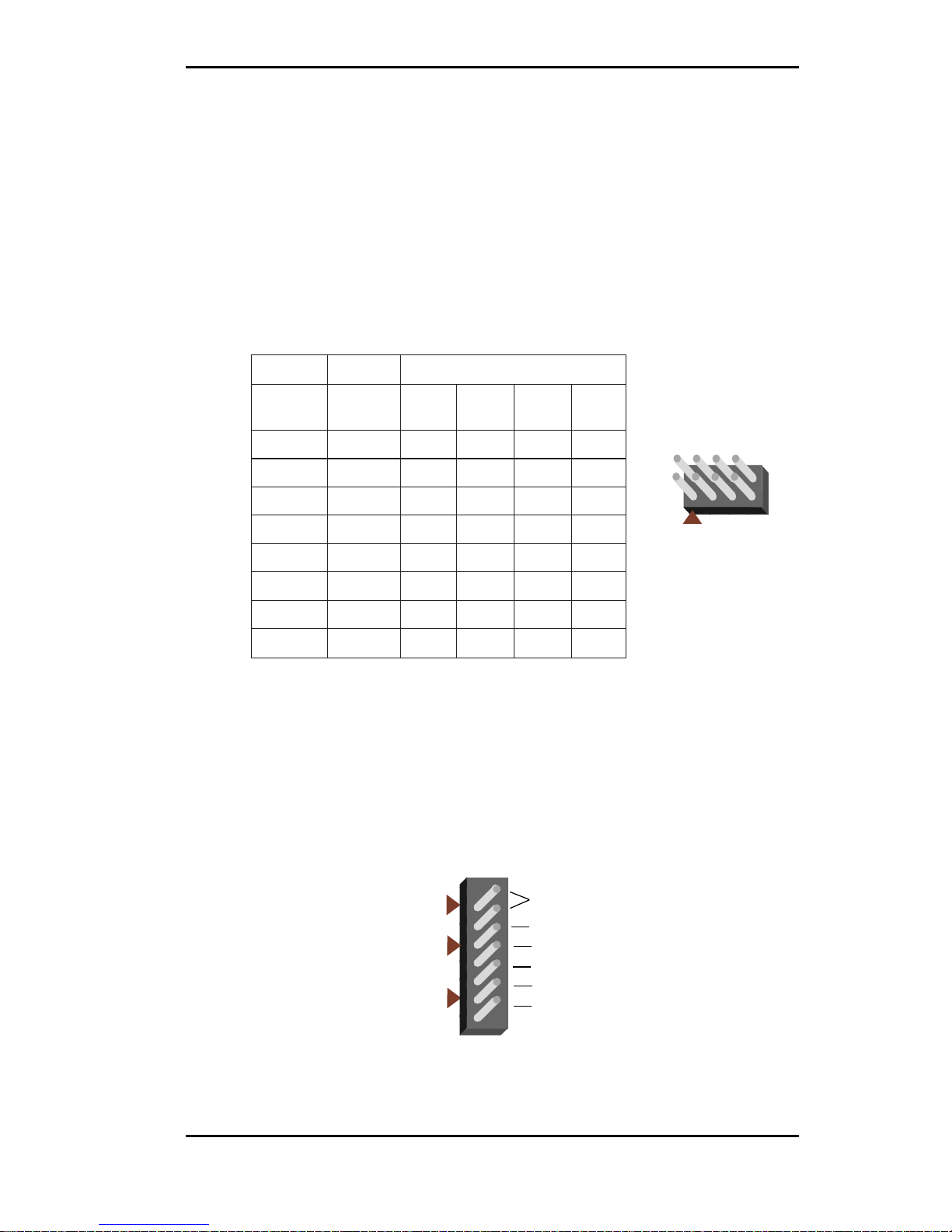
168-Pin DIMM
one
bank
Page 22

Micronics C400 System Board Manual
Chapter 3: Installing the Micronics C400
20
Memory Configurations
DIMM memory configuration is auto-banking and therefore does not need to be installed in any particular order.
The following tables list the most common memory configurations.
T ab le 3-1: Memory Configurations
yromeM1MMID2MMID3MMID
BM846xM1
BM6146xM2
BM6146xM146xM1
BM4246xM246xM1
BM4246xM146xM146xM1
BM2346xM246xM2
BM2346xM4
BM0446xM246xM246xM1
BM0446xM446xM1
BM8446xM246xM246xM2
BM8446xM446xM146xM1
BM8446xM446xM2
BM6546xM446xM246xM1
BM4646xM446xM4
BM4646xM8
BM0846xM846xM2
BM0846xM846xM146xM1
Page 23

Micronics C400 System Board Manual
Chapter 3: Installing the Micronics C400
21
Table 3-1a: Memory Configurations
yromeM1MMID2MMID3MMID
BM6946xM446xM446xM4
BM21146xM846xM446xM2
BM82146xM61
BM82146xM846xM446xM4
BM82146xM846xM8
BM06146xM6146xM4
BM06146xM6146xM246xM2
BM29146xM846xM846xM8
BM29146xM6146xM446xM4
BM29146xM6146xM8
BM42246xM6146xM846xM4
BM65246xM6146xM61
BM65246xM6146xM846xM8
BM02346xM6146xM6146xM8
BM48346xM6146xM6146xM61
BM48346xM2346xM61
BM48346xM2346xM846xM8
Page 24
Micronics C400 System Board Manual
Chapter 3: Installing the Micronics C400
22
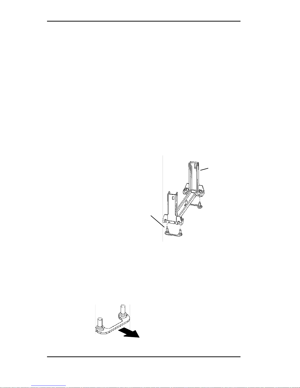
Support Br idge
with Studs
Retention
Base
CPU Installation
The Micronics C400 is designed to support single Pentium
II processors. The Pentium II processor comes installed
in a Single Edge Contact (SEC) cartridge that connects
into "Slot 1" on the system board.
A Retention Mechanism is supplied to anchor the processor to the system board. Attach the Retention Mechanism before inserting the processor.
Installing the CPU Retention Mechanism
Before you begin, verify that your Retention Mechanism
Kit contains the following items:
❏ Retention Base (black plastic module)
❏ Support Bridges with Studs (plastic
mounts).
Follow the steps below to install the kit:
1. Locate the four Retention Base holes (near each end
of the Slot 1 socket). Insert the two Support Bridges
with studs (plastic mounts) from the bottom side of
the Micronics C400 toward the component side
until they snap into place.
(Orient the loops toward
the outer edges of the
system board)
Page 25
Micronics C400 System Board Manual
Chapter 3: Installing the Micronics C400
23
2. Place the Retention Base over the Slot 1 connector
and insert it down into the Support Bridges with
studs. Note the “Keyed” location of both Slot 1 and
the Retention Base.
3. Using a screwdriver, tighten all four
sides of the Retention Base.
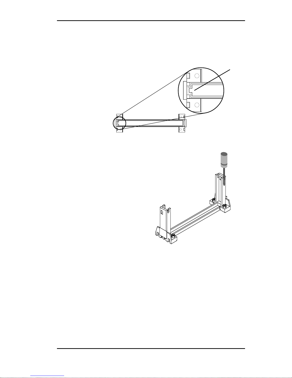
Installing a CPU
Follow the steps below to install the Pentium II processor:
1. Locate the Slot 1 connector (refer to Figure 2-1).
2. If you are installing the boxed version of the Pentium
II processor, follow the instructions in the section
“CPU Installation (Boxed version).”
3. If you are installing the optional Heat Sink Support,
continue to step 4; if not, go to step 5.
Retention Base
Keyed
Page 26

Micronics C400 System Board Manual
4. The Heatsink components consist of a top bar, base
and two pins. Gently insert the Heatsink base into
the holes next to the Slot 1 socket. Push down until
the base snaps into place.
5. Gently insert the processor cartridge down into the
Retention Module, making sure the connector on
the processor cartridge and the Slot 1 connector are
aligned (refer to the keyed location on the previous
page).
6. Push the processor cartridge down until it snaps into
place.
7. Lock the processor cartridge into place by pushing
outward on the tabs located on both sides of the
processor cartridge. The processor cartridge is locked
when the tabs snap into the holes on the side of the
Retention Mechanism.
8. After the processor cartridge is locked into place,
connect the Heatsink’s top bar to the base.
9. Lock the base into place by inserting a pin down into
the base on both sides.
10. Make sure the CPU speed is set correctly (refer to
Chapter 2: Jumper and Connector Settings).
Chapter 3: Installing the Micronics C400
24
Top Bar
Pin
Base
Pin
Page 27

Micronics C400 System Board Manual
Chapter 3: Installing the Micronics C400
25
CPU Installation
Overview
1. Mount the Retention
Mechanism for the
CPU.
2. Mount the (optional)
heatsink support base
onto the system board.
3. Slide the CPU into the
Retention Mechanism.
4. Lock the CPU into the
Retention mechanism
using the tabs.
5. Slide in the Heat Sink
Top Bar, then insert
the pins to lock it in
place.
CPU Installation Overview
Figure 3-1: Installing a CPU
5
1
2
3
4
Page 28

Micronics C400 System Board Manual
Chapter 3: Installing the Micronics C400
26
Figure 3-2: Installing a CPU (Boxed version)
1
2
3
4
3
Install to
system board
CPU Installation (Boxed version)
A boxed version of the CPU is offered through Intel. This
packaging uses an active cooling fan. The mounting
hardware is described below. For detailed instructions,
please refer to the documentation that is supplied with
your CPU.
NOTE: Make sure the CPU speed is set correctly (refer to
Chapter 2: Jumper and Connector Settings).
Page 29

Micronics C400 System Board Manual
Chapter 3: Installing the Micronics C400
27
Installing DIMMs
To install the DIMMs, locate the memory banks on the
system board and perform the following steps:
1. Hold the DIMM so that the notched edge is aligned
with the notch on the DIMM socket (Figure 3-1).
2. Insert the DIMM at a 90 degree angle.
3. Gently push the DIMM straight down until it locks
into place (past the release tabs).
Figure 3-3: Installing a 168-Pin DIMM
Removing DIMMs
To remove DIMMs, follow the steps below:
1. With both thumbs (or fingers), press the release tabs
away from the socket.
2. With the DIMM free from the release tabs, lift the
module up and place in an anti-static bag or package.
Page 30

Micronics C400 System Board Manual
Chapter 3: Installing the Micronics C400
28
Installing a PCI Peripheral Card
The Micronics C400 PCI slots accommodate all PCI peripherals that meet the PCI 2.1 specifications. Follow the
steps below to install a PCI card:
1. Turn the computer system off and remove its cover.
2. Choose an unused PCI slot and remove the slot cover.
3. Insert the card with the bottom edge level to the slot.
Never insert the card at an angle.
4. Carefully push the card straight down, making sure
the card is fully inserted.
5. Replace the screw which holds the card in place.
6. Replace the computer cover.
7. Refer to the PCI card’s documentation additional
instructions regarding installation and software drivers.
Figure 3-4: Installing a PCI Card
Page 31

Micronics C400 System Board Manual
Installing an ISA Peripheral Card
The Micronics C400 ISA slots accommodate all standard
ISA peripherals. Follow the steps below to install an ISA
card:
1. Turn the computer system off and remove its cover.
2. Choose an unused ISA slot and remove the slot cover.
3. Insert the card with the bottom edge level to the slot.
Never insert the card at an angle.
4. Carefully push the card straight down, making sure
the card is fully inserted.
5. Replace the screw that holds the card in place.
6. Replace the computer cover.
7. Refer to the ISA card’s documentation for additional instructions regarding installation and software drivers.
Chapter 3: Installing the Micronics C400
29
Figure 3-5: Installing an ISA Peripheral Card
Page 32

Micronics C400 System Board Manual
Chapter 3: Installing the Micronics C400
30
Installing an AGP Peripheral Card
The Micronics C400 AGP slot can accommodate all AGP
peripherals that meet the Intel AGP bus specifications.
Follow the steps below to install an AGP card:
1. Turn the computer system off and remove its cover.
2. Locate the AGP slot (J12) and remove the slot cover.
3. Insert the card with the bottom edge level to the slot.
Never insert the card at an angle.
4. Carefully push the card straight down, making sure
the card is fully inserted.
5. Replace the screw which holds the card in place.
6. Replace the computer cover.
7. Refer to the AGP card’s documentation for additional instructions regarding installation and software drivers.
Figure 3-6: Installing an AGP Peripheral Card
Page 33

Micronics C400 System Board Manual
31
The BIOS Setup Utility
Configuration
After the Micronics C400 system board and all hardware
is installed, the system is ready for configuration. Before
turning on the computer, make sure all cables are correctly connected and all jumpers are correctly set.
We recommend that you keep the computer cover off the
first time you boot the system. This makes it faster and
easier to correct any difficulties that might arise.
Initial Boot Up
Power up the Micronics C400. If the system does not
properly boot, check all your cables and peripherals for
bad connections. You may also get POST codes or error
messages. If this occurs, consult Appendix B and C for a
guide to possible solutions.
After the system properly boots, it is ready to be configured. The following information explains the proper
procedures for BIOS configuration.
Setup
The Setup program is used to configure the computer’s
BIOS (Basic Input/Output System). The computer’s
BIOS is responsible for configuring the system board and
providing hardware information to the operating system.
In order for the computer to run properly, run the Setup
procedure after first installing the system board and
whenever you make a hardware change to the system.
Chapter 4: The BIOS Setup Utility
4
Chapter
Page 34

Micronics C400 System Board Manual
32
When the system is turned on, it performs a memory test,
and a BIOS identification and system information screen
is displayed on your monitor, as shown in Figure 4-1.
Figure 4-1: P ower-Up Screen
When “Press DEL to enter Setup” appears at the bottom
of the screen, press the <DEL> key to start the Setup
program. The main CMOS Setup utility screen (Figure
4-2) appears. Note that the Setup program can only be
activated during the boot sequence.
Chapter 4: The BIOS Setup Utility
Page 35

Micronics C400 System Board Manual
Chapter 4: The BIOS Setup Utility
33
Running the Setup Program
The Micronics C400 system board has six primary CMOS
configuration screens: main setup menu, Standard CMOS
Setup, BIOS Features Setup, Chipset Features Setup, PNP/
PCI Configuration and Integrated Peripherals screen.
In addition, there are four screens containing options that
do not have to be set unless you want to: the Power
Management Setup screen, the Supervisor Password, the
User Password and the IDE HDD Auto Detection screen.
The main menu screen also contains the following options:
Load BIOS Defaults, Load Setup Defaults, HDD Low Level
Format, Save & Exit Setup and the Exit Without Saving.
To select any of these screens or options, use the arrow keys
(<↑←↓→>) to move the highlight to the desired item and
press <ENTER>. NOTE: A brief description of each high-
lighted selection appears at the bottom of the screen.
Figure 4-2: CMOS Main Screen
Page 36

Micronics C400 System Board Manual
Chapter 4: The BIOS Setup Utility
34
Standard CMOS Setup
The STANDARD CMOS SETUP allows checking or modification of general configuration information. To access
the STANDARD CMOS SETUP screen, highlight this
option on the main menu screen and press <ENTER>.
Figure 4-3. Standard CMOS Setup Screen
Date and Time
To set the date, use <→/←↑/↓> arrow keys to highlight
the date and follow the same procedure to set the time.
Hard Disks Setup
The BIOS supports up to four IDE drives. You can specify
the physical and electronic properties of the disk drives
installed. Relevant specifications include the type, number of cylinders (CYLS), heads (HEAD), write precompensation time (PRECOMP), read/write head landing zone (LANDZ), number of sectors per track (SEC-
Page 37

Micronics C400 System Board Manual
Chapter 4: The BIOS Setup Utility
35
TOR), and HDD mode (MODE). NOTE: We recommend
that you select type Auto for all drives.
Diskette A or B
To configure a floppy drive added to or removed from
your computer, use <→/←↑/↓> arrow keys to select the
desired drive. Use the <PU/PD/+/-> arrow keys to
change the setting until it matches the floppy drive you
installed. The BIOS supports 2.88MB, 1.44MB, 1.2MB,
720KB and 360KB floppy drives.
Video
Select the type of video card installed into your system.
The default setting is EGA/VGA.
Halt On
During the Power-On Self-Test (POST), the system
stops if the BIOS detects a hardware error. The default
setting is All Errors.
Base/Extended/Other Memory
A small section in the lower right corner of the screen
displays important information about your system that
includes the base, extended and other memory sizes. They
are updated automatically by the Setup program according
to the status detected by the BIOS self-test.
Page 38

Micronics C400 System Board Manual
Chapter 4: The BIOS Setup Utility
BIOS Features Setup
This feature allows you to set the Award enhanced BIOS
options of your choice. To access the BIOS FEATURES
SETUP screen, highlight this option on the main menu
screen and press <ENTER>.
Figure 4-4: BIOS Features Setup Screen
Virus Warning
When enabled, the system BIOS will report a warning
message if a program attempts to write to the boot sector
or partition table of the hard disk drive.
CPU L2 Cache ECC Checking
This selection enables the internal CPU L2 Cache ECC
checking function. The default setting is Enabled.
External Cache
The External Cache selection enables or disables the
external (L2) cache and the onboard secondary cache.
The default setting is Enabled.
36
Page 39

Micronics C400 System Board Manual
Chapter 4: The BIOS Setup Utility
37
Quick Power-On Self-Test
When enabled, this selection will reduce the amount of
time required to run the Power-On Self-Test (POST). A
quick POST skips certain steps. We recommend that you
disable quick POST. The default setting is Enabled.
Boot Sequence
Boot Sequence selects the order in which the system
searches for a boot disk. The default setting is C, A, SCSI.
Swap Floppy Drive
This selection can be set to remap the floppy drives. When
set to Enabled, drive A: becomes drive B: and drive B:
becomes drive A:.
Boot Up Floppy Seek
When set to Enabled (default), the BIOS tests (seeks)
floppy drives to determine whether they have 40 or 80
tracks. Drives with 720KB, 1.2MB and 1.44MB capacity
all have 80 tracks.
Boot Up Numlock Status
Toggle between On and Off to control the state of the
NumLock key when the system boots. When toggled On,
the numeric keypad generates numbers instead of controlling cursor operations. The default setting is On.
Boot Up System Speed
Select the system boot up speed. The default setting is
High.
Page 40

Micronics C400 System Board Manual
Chapter 4: The BIOS Setup Utility
38
Gate A20 Option
Gate A20 refers to the way the system addresses memory
above 1MB (extended memory). When set to Fast
(default), the system chipset controls Gate A20. When
set to Normal, a pin in the keyboard controller controls
Gate A20. Setting Gate A20 to Fast improves system
speed, particularly with OS/2 and Windows.
Typematic Rate Setting
This selection enables or disables the Type Rate and
Typematic Delay options that control the speed at which
a keystroke is repeated.
Typematic Rate/Typematic Delay
Typematic Rate selects the typematic rate at which
characters repeat when a key is held down. The default
setting is 6 (Chars/Sec). Typematic Delay controls the
gap between key compression and appearance of the
characters on the screen. The default setting is 250
(Msec).
Security Option
This selection determines whether the password will be
asked for in every system boot or only when entering into
the Setup (default) program.
PCI/VGA Palette Snoop
Alters the VGA palette setting while graphic signals pass
through the feature connector of the VGA card and are
processed by the MPEG card. Enable this option only if
you have MPEG connections through the VGA feature
connector; this means you can adjust PCI/VGA palettes.
The default setting is Disabled.
Page 41

Micronics C400 System Board Manual
OS Select for DRAM>64MB
This selection allows you to select the amount of memory
installed for your operating system. The default setting is
Non-OS2. Select OS2 only when running OS/2 operating systems with greater than 64MB of system memory.
Video BIOS Shadow
Enabling this selection allows you to shadow the BIOS on
the video card for faster video performance. Some video
cards do not support video BIOS shadowing. Disable this
option if problems occur.
Chapter 4: The BIOS Setup Utility
39
Page 42

Micronics C400 System Board Manual
Chapter 4: The BIOS Setup Utility
40
Chipset Features Setup
The Chipset Features Setup allows you to program the Intel
440BX AGP chipset features. To access the CHIPSET
FEATURES SETUP screen, highlight this option on the
main menu screen and press <ENTER>.
Figure 4-5: Chipset Features Setup Screen
SDRAM CAS Latency Time
When synchronous DRAM is installed, the number of
clock cycles of CAS latency depends on the DRAM timing.
Do not reset this field from the default value specified.
DRAM Data Integrity Mode
Select Parity or ECC (error-correcting code), according to
the type of installed DRAM.
System BIOS Cacheable
Selecting Enabled allows caching of the system BIOS ROM
at F0000h-FFFFFh, resulting in better system performance.
Page 43

Micronics C400 System Board Manual
Chapter 4: The BIOS Setup Utility
41
However, if any program writes to this memory area, a
system error may result.
Video BIOS Cacheable
Selecting Enabled allows caching of the video BIOS ROM
at C0000h to C7FFFh, resulting in better video performance. However, if any program writes to this memory
area, a system error may result.
8-Bit/16-Bit I/O Recovery Time
The I/O recovery mechanism adds bus clock cycles between PCI-originated I/O cycles to the ISA bus. This delay
takes place because the PCI bus is so much faster than the
ISA bus. These two fields let you add recovery time (in bus
clock cycles) for 16-bit and 8-bit I/O.
Video RAM Cacheable
Enable or disable the caching of the video RAM. The
default settings is Disabled.
Memory Hole at 15M-16M
You can reserve this area of system memory for the ISA
adapter ROM. When this area is reserved, it cannot be
cached.
Passive Release
When enabled, CPU to PCI bus accesses are allowed
during passive release. Otherwise, the arbiter only accepts
another PCI master access to local DRAM.
Delayed Transaction
The chipset has an embedded 32-bit posted write buffer to
support delay transaction cycles. Select Enabled to support compliance with PCI specification version 2.1.
Page 44

Micronics C400 System Board Manual
Chapter 4: The BIOS Setup Utility
42
AGP Aperture Size (MB)
Select the size of the Accelerated Graphics Port (AGP)
aperture. The aperture is a portion of the PCI memory
address range dedicated for graphics memory address space.
Host cycles that hit the aperture range are forwarded to the
AGP without any translation.
Power-Up State
Specifies how the computer responds following a power
failure. Stay Off keeps power off until the power button is
pressed. Last State restores previous power state before a
power failure. Power On restores power without restoring
previous power state.
Current System Temperature
Displays the current system temperature if your computer
contains a monitoring system.
Current CPUFAN 1/2 Speed
Displays the current speed of up to three CPU fans if your
computer contains a monitoring system.
Page 45

Micronics C400 System Board Manual
Chapter 4: The BIOS Setup Utility
43
Power Management Setup
The Power Management Setup option controls the power
management functions of the system. To access the
POWER MANAGEMENT SETUP screen, highlight this
option on the main menu screen and press <ENTER>.
Figure 4-6: P ower Management Screen
ACPI Aware O/S
Advanced Configuration and Power Interface (ACPI)
enables your PC to automatically turn on and off. ACPI
facilitates the transmission of commands from peripherals
such as CD-ROMs, hard disk drives and modems to
activate the PC when it is in a low-power sleep mode.
NOTE: This selection should be set to Yes when using
Windows 98.
Page 46

Micronics C400 System Board Manual
SYNC+Blank System turns off vertical and horizontal
synchronization ports and writes blanks to the
video buffer.
DPMS Support Select this option if your monitor supports the
Display Power Management Signaling
(DPMS) standard of the Video Electronics
Standards Association (VESA). Use the
software supplied for your video subsystem to
select video power management values.
Blank Screen System only writes blanks to the video buffer.
Power Management
This selection allows you to select the type (or degree) of
power saving for Sleep, Standby and Suspend modes. The
options are: Maximum Power Savings, User Defined and
Minimum Power Savings.
PM Control By APM
When enabled, power management is controlled by the
Advanced Power Management (APM) feature, which
gives better power savings. The default setting is YES.
Video OFF Method
This selection defines the video off method in standby
mode. The following table describes each option:
Video OFF After
Select the mode in which you want the monitor to blank.
The default setting is Standby.
Chapter 4: The BIOS Setup Utility
44
Max Saving Maximum power savings. Inactivity period is
1 minute in each mode.
User Define Set each mode individually. Select time-out
periods in the PM Timers section.
Min Saving Minimum power savings. Inactivity period is
1 hour in each mode (except the hard drive).
Page 47

Micronics C400 System Board Manual
Modem Use IRQ
Select an IRQ setting to be used by the modem if Resume
by Ring is enabled.
Doze Mode
After the selected period of system inactivity (1 minute to
1 hour), the CPU clock runs at slower speed while all other
devices still operate at full speed.
Standby Mode
After the selected period of system inactivity (1 minute to
1 hour), the fixed disk drive and the video shut off while all
other devices still operate at full speed.
Suspend Mode
After the selected period of system inactivity (1 minute to
1 hour), all devices except the CPU shut off.
HDD Power Down
After the selected period of drive inactivity (1 to 15
minutes), the hard disk drive powers down while all other
devices remain active.
Throttle Duty Cycle
This option allows you to select the percentage of time that
the CPU clock runs when the system enters Doze Mode.
VGA Active Monitor
Select whether or not video activity restarts the global
timer for Standby Mode.
Chapter 4: The BIOS Setup Utility
45
Page 48

Micronics C400 System Board Manual
46
Soft Off By PWR-BTTN
This selection allows you to set your system’s power button
to Delay 4 Sec or Instant Off. When set to Delay 4 Sec and
the power button is pushed within 4 seconds, the system
will go into suspend mode. When the power button is
pushed over 4 seconds, the system will power off.
CPUFAN Off In Suspend
When enabled, this selection turns off the CPUFAN in
Suspend mode.
Resume By Ring
When this feature is turned on, the system will wake up
when an incoming call is detected on your modem. You
must set up the Mode Use IRQ selection.
Wake On LAN
This selection specifies whether the computer responds to
an incoming call or not. Wake On LAN requires a PCI
add-in network interface card with remote wakeup capabilities and an ATX power supply that can handle the
power requirement for 5V standby.
IRQ 8 Break Suspend
Sets the monitoring of IRQ8 (Real Time Clock) so that it
does not awaken the system from Suspend mode.
Reload Global Timer Events
You can disable monitoring of common interrupt requests
so they do not awaken the system from, or reset activity
timers for Standby mode.
Chapter 4: The BIOS Setup Utility
Page 49

Micronics C400 System Board Manual
Chapter 4: The BIOS Setup Utility
PnP/PCI Configuration Setup
The PnP/PCI Configuration Setup option sets the various
system functions and internal addresses of PnP and PCI
devices and onboard PCI IDE controller. To access the
PnP/PCI CONFIGURATION SETUP screen, highlight
this option on the main menu screen and press <ENTER>.
Figure 4-7: PnP/PCI Configuration Screen
PnP OS Installed
When set to Yes, this selection allows the system to work
with a Plug and Play (PnP) operating system such as
Windows 95. The PnP BIOS will configure only PCI and
ISA Plug and Play cards needed to boot the system, and
allow the operating system or device drivers to configure
the remaining cards. The default setting is No.
Resources Controlled By
The Micronics C400’s Plug and Play BIOS can automatically configure all the boot and Plug and Play-compatible
47
Page 50

Micronics C400 System Board Manual
Chapter 4: The BIOS Setup Utility
48
devices. If you select Auto all the interrupt request (IRQ)
and DMA assignment fields disappear, as the BIOS automatically assigns them.
Reset Configuration Data
Select Enabled to reset Extended System Configuration
Data (ESCD) when you exit Setup. This selection allows
the PnP BIOS to detect your PCI and ISA PnP devices
and reallocate resources to them. The default setting is
Disabled.
IRQ n Assigned To
When resources are controlled manually, assign each
system interrupt as one of the following types, depending
on the type of device using the interrupt:
Legacy ISA Devices compliant with the original PC
AT bus specification, requiring a specific
interrupt (such as IRQ4 for COM 1) or
older ISA cards that use jumpers to adjust
resources.
PCI/ISA PnP Devices compliant with the Plug and Play
standard, whether designed for PCI or
ISA bus architecture.
DMA n Assigned To
When resources are controlled manually, assign each system DMA channel as one of the following types, depending
on the type of device using the interrupt:
Legacy ISA Devices compliant with the original PC AT
bus specification, requiring a specific DMA
channel or older ISA cards that use jumpers to adjust resources.
PCI/ISA PnP Devices compliant with the Plug and Play
standard, whether designed for PCI or ISA
bus architecture.
Page 51

Micronics C400 System Board Manual
Used Memory Base Address
Select a base address for the memory area used by any
peripheral that requires high memory.
Used Memory Length
Select a length of memory area specified by any peripheral
that requires high memory. NOTE: This option is available
only if Used Memory Base Address is not set at N/A.
Load BIOS Defaults
This selection loads the BIOS default values that would
allow safe booting of the system in the event of a BIOS
configuration memory loss. To select LOAD BIOS
DEFAULTS, highlight this option on the main menu screen
and press <ENTER>. Press <Y> or <N> when the
program prompts you with the Load BIOS Defaults question.
Load Setup Defaults
This selection allows automatic configuration of all the
options in the Standard CMOS Setup, BIOS Features
Setup and Chipset Features Setup with the setup defaults.
If problems are encountered after loading the setup defaults, reboot the system and load the BIOS defaults. To
select LOAD SETUP DEFAULTS, highlight this option on
the main menu screen and press <ENTER>. Press <Y>
or <N> when the program prompts you with the Load
Setup Defaults question.
Chapter 4: The BIOS Setup Utility
49
Page 52

Micronics C400 System Board Manual
Chapter 4: The BIOS Setup Utility
50
Integrated Peripherals
This option sets the addresses of I/O subsystems that
depend on the integrated peripherals controller in your
system. To access the INTEGRATED PERIPHERALS
screen, highlight this option on the main menu screen and
press <ENTER>.
Figure 4-8: Integr ated P eripherals Configuration Screen
IDE HDD Block Mode
Block mode is also called block transfer, multiple commands, or multiple sector read/write. If your IDE hard
drive supports block mode (most new drives do), select
Enabled (default) for automatic detection of the optimal
number of block read/writes per sector the drive can
support.
IDE Primary/Secondary Master/Slave PIO
The four IDE PIO (Programmed Input/Output) fields allow you to set a PIO mode (0-4) for each of the four IDE
Page 53

Micronics C400 System Board Manual
Chapter 4: The BIOS Setup Utility
51
devices that the onboard IDE interface supports. Modes 0
through 4 provide successively increased performance. In
Auto (default) mode, the system automatically determines
the best mode for each device.
IDE Primary/Secondary Master/Slave UDMA
Set the UDMA (Ultra DMA/33) mode for the specified
onboard IDE interface. Ultra DMA/33 is a hard drive
interface protocol that increases the burst data transfer
rate to 33MBytes per second. NOTE: Your hard drive and
operating environment must both support the UDMA
mode.
On-Chip Primary/Secondary PCI IDE
The integrated peripheral controller contains an IDE interface with support for two IDE channels. Select Enabled to
activate each channel separately.
USB Keyboard Support
Select Enabled if your system contains a Universal Serial
Bus (USB) controller and you have USB keyboard.
Onboard FDC Controller
Select Enabled (default) to use the floppy disk controller
installed on the system board. If you install an add-in
controller or the system has no floppy drive, select Disabled.
Onboard Serial Port 1/2
Select a logical COM port name and matching address for
the first and second serial ports.
Page 54

Micronics C400 System Board Manual
52
UART2 Mode
The second serial port offers the following Infrared interface modes: Standard, HPSIR: IrDA-compliant serial infrared port, and ASK-IR: Amplitude shift keyed infrared
port. Standard mode is the default.
Onboard Parallel Port
Select an address and interrupt for the physical parallel
(printer) port.
Onboard Parallel Mode
Select an operating mode for the onboard parallel (printer)
port. Select SPP (default) unless your hardware and software require one of the other modes offered in this field.
ECP Mode Use DMA
Select a DMA channel for the port. The default setting is
channel 3.
Chapter 4: The BIOS Setup Utility
Page 55

Micronics C400 System Board Manual
53
Supervisor Password
The Supervisor Password utility allows you to setup, change
or disable the password stored in the BIOS. The Supervisor
Password allows access to the system Setup. To setup or
change a password, highlight the SUPERVISOR PASSWORD option on the main menu screen and press <ENTER>.
The password can be no more than eight characters long.
The program will prompt you to confirm the new password
before exiting and enabling the utility. To disable the
password, press <ENTER> when the program prompts
you to enter the new password.
WARNING: If you forget the Supervisor Password, it cannot be
disabled without resetting the CMOS.
User Password
The User Password utility allows you to setup, change or
disable the password stored in the BIOS. Follow the same
procedure used to setup the Supervisor Password. The
User Password allows power-on access to the system, but
will not allow you to modify the CMOS settings.
NOTE: The User Password can only be set after setting the
Supervisor password.
Chapter 4: The BIOS Setup Utility
Page 56

Micronics C400 System Board Manual
54
IDE HDD Auto Detection
The IDE HDD Auto Detection option provides auto
configuration of the hard drive installed in your system. To
access the IDE HDD Auto Detection screen, highlight
this option on the main menu screen and press <ENTER>.
Figure 4-9: IDE HDD Auto Detection Screen
The IDE HDD Auto Detection option provides auto
configuration of the hard drive installed in your system. It
supports LBA, Large and Normal modes.
If your hard disk drive’s capacity is under 528MB, select
Normal mode. NOTE: It is recommended that you select
Normal mode for your hard disk drive if you will be using
UNIX. If the system’s hard disk drive has a capacity of over
528MB and supports LBA functions, you may enable either
the LBA mode or the Large Mode.
Chapter 4: The BIOS Setup Utility
Page 57

Micronics C400 System Board Manual
55
HDD Low Level Format
Diamond recommends that only trained technicians use this
utility. This selection allows you to perform a low level
format of your hard disk drive. To select the HDD LOW
LEVEL FORMAT option, highlight this option on the main
menu screen and press <ENTER>.
Figure 4:10: HDD Low Level Format Screen
The selections available are: Low Level Format Utility,
Select Drive Bad Track List and Preformat.
WARNING: This utility should not be run on an IDE or EIDE
hard drive unless the manufacturer of the hard drive instructs
you to do so.
Chapter 4: The BIOS Setup Utility
Page 58

Micronics C400 System Board Manual
Save and Exit Setup
This selection saves the changes you have made in the
setup program, then exits and reboots the system. After
making all modifications in the setup program, exit to the
main menu screen. Highlight the SAVE AND EXIT SETUP
option and press <ENTER>. Press <Y> to confirm the
changes made and <N> or <ESC> if additional modifications are needed before exiting the setup program.
Exit Without Saving
This selection abandons all previous settings, then exits
and reboots the system. From the main menu screen
highlight the EXIT WITHOUT SAVING option and press
<ENTER>. Press <Y> and the system will exit the setup
program, then reboot without saving any of the changes
made.
Chapter 4: The BIOS Setup Utility
56
Page 59

Micronics C400 System Board Manual
Chapter 5: Special Features
57
Chapter
5
Special Features
The Micronics C400 achieves high reliability, performance
and scalability with numerous features.
Intel’s 440BX AGPset
In the competitive world of system board chipsets, Intel’s
new 440BX places at the top with its support for the
100MHz Front Side Bus (FSB) technology. The 440BX is the infrastructure
behind the 100MHz FSB technology.
Along with PC-100 memory and Intel’s
new versions of the Pentium II processor
family, the 440BX AGPset adds a new
data highway that should post a substantial increase in bus and memory access. The flexibility of
the 440BX allows for support of the first generation Pentium
II processors at 66MHz FSB speeds.
Accelerated Graphics Port (AGP)
With the introduction of the Pentium II and the 440LX
AGPset, graphics took the next step onto the AGP freeway. The AGP bus is
faster than the current
33MHz PCI bus. It provides a direct connection
between the graphics
subsystem and system
memory. AGP, with dual
528MB/s data path, surpasses PCI’s 132MB
bottleneck.
Page 60

Micronics C400 System Board Manual
Chapter 5: Special Features
58
SDRAM (Synchronous DRAM)
SDRAM is memory that can synchronize itself with the
computer’s clock. This synchronization reduces time
delays and allows for fast consecutive read and write
capability.
SDRAM can
add as much as
10% to the
overall system performance.
Intel’s release of the 440BX AGPset allows SDRAM to
operate up to a new standard at 100MHz. At these speeds,
a new standard of SDRAM or PC-100 SDRAM is
required. PC-100 MHz memory is backwards compatible
to run at 66MHz, however, a non PC-100 SDRAM may not
be used on a 100MHz FSB system.
Wake On LAN
This feature offers you a way to access a local-area or wide-
area network or modem to turn on desktop PCs remotely.
The wake-up control located on the Micronics C400
system board collects input from a Wake On LAN enabled
adapter and the PC's power switch. It then routes its
output to the power-supply activation circuitry. You can
power up your PC or multiple PCs from a remote location
and manage networks more efficiently.
Wake On LAN, along with system management tools such
as Intel LANDesk Client Manager, can work together to
cut computing costs by allowing time-consuming PC management tasks to be done when network bandwidth is less
demanding.
Page 61

Micronics C400 System Board Manual
Chapter 5: Special Features
59
Ultra DMA/33 IDE
A hard drive interface protocol that
increases the burst data transfer rate
to 33MBytes per second. Prior to this
protocol, Mode-4 protocol has been
the fastest at 16.6MB per second. This new protocol is
supported by Intel’s 440LX and 440BX AGPsets.
Universal Serial Bus (USB)
The simple and flexible way to connect devices to your
desktop or notebook PC. USB allows virtually unlimited PC
expansion
with no more
hassles over
add-in cards,
dip switches,
jumper cables,
software drivers, IRQ settings, DMA channels and I/O addresses. With
USB, you can attach and detach peripherals without opening the computer or even shutting it down.
Page 62

Micronics C400 System Board Manual
Chapter 5: Special Features
60
Page 63

Micronics C400 System Board Manual
Appendix A: Technical Information
61
A
Appendix
Specifications
Part Number: 09-00351-xx
Processor: Single Intel Slot 1 for
Intel Celeron 233-333MHz
(66MHz FSB).
Intel Pentium II 350-450MHz
(100MHz FSB).
CPU Clock Select: Support for 66/100MHz CPU bus
Chipset: Intel 440BX AGPset
Intel PIIX4e
Form Factor: Mini ATX footprint (7.5” x 12”)
20-pin ATX power connector
Expansion: One AGP slot
Four 32-bit PCI slots
One shared PCI/ISA slot
One 16-bit ISA slot
BIOS: Award BIOS on 1MB Flash
APM 1.2
PCI auto configuration
Auto detection of memory size
Auto detection and display of EDO
and SDRAM memory.
Auto detection of IDE hard disk types
Soft Power Down (for ATX power
supply)
Instant On and Quick Boot
Multi-boot II
DMI 2.0/SMI/ACPI
Page 64

Micronics C400 System Board Manual
Appendix A: Technical Information
Keyboard/Mouse: PS/2 style keyboard and mouse connector
Memory Capacity: Three 3.3V unbuffered 64-bit DIMM sockets
Maximum memory - 768MB for SDRAM
(PC-100MHz SDRAM memory supported)
Supports EDO and SDRAM
ECC supported via chipset when using parity
Hardware Microprocessor System Hardware Monitor
Management: CPU Fan Speed Monitoring (3-pin header)
Chassis Fan Speed Monitoring (3-pin header)
I/O Ports: Two high speed serial ports (16550 compatible)
One 25-pin Parallel Port (ECP and EPP)
IrDA compliant IR header
Two USB connectors
SB-LINK header to support legacy Sound Blaster
compatible PCI audio card.
Floppy Port: Supports 360K - 2.88MB formats
Auto detection of add-in floppy controllers
PCI IDE Ports: Ultra DMA/33 IDE
Two 40-pin IDE connectors
(Primary and Secondary IDE).
Multiple sector transfer support
Auto detection of add-in IDE board
Supports all ATAPI devices
Wake On LAN: Wake On LAN ready for remote monitoring
(3-pin header). NOTE: You must use a Wake On
LAN supported Ethernet adapter and an ATX power
supply that can handle the power requirement for 5V
standby.
62
Page 65

Micronics C400 System Board Manual
Appendix A: Technical Information
63
Environmental Specifications
The environment in which the Micronics C400 is located is
critical. Diamond recommends the following environmental specifications:
Temperature Range
Operating: 50 to 104 degrees Fahrenheit (10 to 40 degrees Celsius).
Non -Operating: 50 to 140 degrees Fahrenheit (10 to 60 degrees
Celsius).
Shipping: -22 to 140 degrees Fahrenheit (-30 to 60 degrees
Celsius).
Relative Humidity
Operating: 20% to 80%.
Non-Operating: 5% to 90%.
Page 66

Micronics C400 System Board Manual
Appendix A: Technical Information
64
Battery Disposal
WARNING:
Please do not open battery, dispose of in fire, recharge, put in
backwards or mix with used or other battery types. The battery
may explode or leak and cause personal injury.
Page 67

Micronics C400 System Board Manual
Appendix A: Technical Information
65
Support and Information Services
Diamond offers a variety of support and information services to help you get the most from your product. The
following services are available:
▲ Technical Support
▲ Electronic Bulletin Board Service (BBS)
▲ Return Materials Authorization (RMA)
▲ Fax-On-Demand
▲ World Wide Web
▲ Customer Service
Refer to Table A-1 for details on these services.
Technical Support
If you need technical assistance, our Technical Support
Engineers will be glad to help you. You can contact us via
telephone, fax or BBS. Before calling Technical Support
please have the following information ready:
❏ The model name part number and serial number of your
Diamond product, which is silk screened on the back of
the Micronics C400 system board.
❏ Your computer information such as CPU type, operating
system, amount of installed memory and other peripherals installed in your computer.
❏ Try to call from the location of your computer.
NOTE: For Return Material Authorization purposes, please
keep a copy of your product receipt.
Page 68

Micronics C400 System Board Manual
Appendix A: Technical Information
66
Table A-1: Support and Information Services
ecivreSyrtnuoCrebmuNenohpeleT
plehenohpeviL-troppuSlacinhceT
sreenignEtroppuSlacinhceTmorf
ASU
KU
ynamreG
ecnarF
cificaP-aisA
5(
14
)
0542-769
5(14)
1042-769
)xaF(
)liam-E(moc.mmdnomaid@tpushcet
44+
444-444-9811-
44+
544-444-9811-
)xaF(
033-662-1518-94+
616183551)0(33+
3613-452-56+
)xaF(7043-452-56+
ecivreSdraoBnitelluBcinortcelE
erawtfosnonoitamrofnI-)SBB(
rehtodnasesaelerwen,sedargpu
noitamrofnilufpleh
ASU
KU
ynamreG
)145(
4442-769
44+
)sbpK8.82(514-444-9811-
xelf65K)spbK65(213-144-9811-44+
)dradnats
)sbpK8.82(333-662-1518-94+
)NDSIoruE)spbK65(433-662-1518-94+
xelf65K)spbK65(653-662-1518-94+
)dradnats
)noitazirohtuAslairetaMnruteR(AMR
riaperrofstcudorpnruteR-
ASU
(
008
)
6485-864
(
804
)
8047-523
)xaF(
metsysdetamotuA-dnameD-nO-xaF
lacinhcet,erutaretiltcudorprof
noitamrofnilufplehrehtodnasnitellub
ASU
ynamreG
(
008
)
0300-083
233-662-1518-94+
tcudorP-beWediWdlroW
sserp,troppuslacinhcet,noitamrofni
lufplehrehtodnasesaeler
noitamrofni
ASU
KU
ynamreG
www//:ptth
moc.mmdnomaid
www//:ptth
ku.oc.mmdnomaid
www//:ptth
ed.mmdnomaid
redrO-ecivreSremotsuC
dnomaiD
stcudorp
ASU
KU
ynamreG
cificaP-aisA
)008(
6485-864
(
804
)xaF(8047-523)
)liam-E(moc.mmdnomaid@ecivresremotsuc
44+
444-444-9811-
44+
544-444-9811-
)xaF(
033-662-1518-94+
3613-452-56+
)xaF(7043-452-56+
Page 69

Micronics C400 System Board Manual
Appendix B: POST Codes
67
Appendix
B
POST Codes
The following tables list the Power On Self Test (POST)
codes, names and solutions. EISA POST codes are typically
output to port address 300h. ISA POST codes are output
to port address 80h.
Code
(hex)
Name Description
C0 Turn Off Chipset Cache OEM Specific-Cache control
1 Processor Test 1 Verification Processor Stat us (1FLAGS) Tests the following
processor status flags: carry, zero, sign, overflow, The
BIOS sets each flag, verifies they are set, then turns
each flag off and v e rifies it is off .
2 Processor Test 2 Read/Write/Verify all CPU registers except SS, SP, and
BP with data pattern FF and 00.
3 Initialize Chips Disable NMI, PIE, AIE, UEI, SQWV Disable video,
parity checking, DMA. Reset math coprocessor. Clear
all page registers, CMOS shutdown byte. Initialize timer
0, 1, and 2, including set EISA timer to a known state.
Initialize DMA controllers 0 and 1 Initialize interrupt
controllers 0 and 1 Initialize EISA ext ended registers.
4 Test Memory Refresh Toggle RAM must be periodically refreshed to keep the
memory from decaying. This function ensures that the
memory refresh function is working prop erly.
5 Blank video, Initialize keyboard Keyboard controller initialization.
6Reserved
7 Test CMOS Interface and Battery
Status
Verifies CMOS is working correctly,
BE Chipset Default Initialization Program chipset registers with power on BIOS defaults.
C1 Memory presence Test OEM Specific-Test to size on-board memory
C5 Early Shadow OEM Specific-Early Shadow enable for fast boot.
C6 Cache presence test External cache si ze detection
8 Setup low memory Early chip set initialization. Memory presence test.
OEM chip set routines. Clear low 64K of memory. Test
first 64K memory.
9 Early Cache Initialization Cyrix CPU initialization Cache initialization
A Setup Interrupt Vector Table Initialize first 120 interrupt vectors with
SPURIOUS_INT_HDLR and initialize INT 00h-1Fh
according to INT_TBL
B Test CMOS RAM Checksum Test CMOS RAM Checksum, if bad, or insert key
pressed, load def aults.
C Initialize Keyboard Detect type of keyboard controller (optional)x Set
NUM_LOCK status.
D Initialize Video Interface Detect CPU clock. Read CMOS location 14h to find out
type of video in use. Detect and Initialize Video
Adapter.
E Test Video Memory Test video memory, w rite sign-on message to screen.
Setup shadow RAM - Enable shadow according to
Setup.
F Test DMA BIOS checksum test. Controller 0 Keyboard detect and
Page 70

Micronics C400 System Board Manual
Appendix B: POST Codes
68
Code
(hex)
Description
10 Test DMA Controller 1
11 Test DMA Page Registers Test DMA Page Registers.
12-13 Reserved
14 Test Timer Counter 2 Test 8254 Timer 0 Counter 2.
15 Test 8259-1 Mask Bits Verify 8259 Channel 1 masked ts interrupts by
alternately turning off and on the interrupt lines.
16 Test 8259-2 Mask Bits Verify 8259 Channel 2 masked interrupts by alternately
turning off and on the interrupt lines.
17 Test Stuck 8259's Interrupt Bits Turn off interrupts then verify interrupt mask register is
on.
18 Test 8259 Interrupt Functionality Force an interrupt and verify the interrupt occurred.
19 Test Stuck NMI Bits (Parity/IO
Check)
Verify NMI can be cleared.
1A Display CPU clock
1B-1E Reserved
1F Set EISA Mode If EISA non-volatile memory checksum is good,
execute EISA initialization. If not, execute ISA tests an
clear EISA mode flag.Test EISA Configuration Memory
Integrity (checksum & communication interface).
20 Enable Slot 0 Initialize slot 0 (System Board).
21-2F Enable Slots Initialize slots 1 through 15.
1-15
30 Size Base and Size base memory from 256K to 640K Extended
Memory and extended memory above 1MB.
31 Test Base and Test base memory from 256K to 640K Extended
Memory and extended memory above 1MB using
various patterns. NOTE: This test is skipped in EISA
mode and can be skipped with ESC key in ISA mode.x
32 Test EISA If EISA Mode flag is set then test Extended Memory
EISA memory found in slots initialization.x NOTE:
This test is skipped in ISA mode and can be skipped
with ESC keyin EISA mode.
33-3B Reserved
3C Setup Enabled
3D Initialize & Install Mouse Detect if mouse is present, initialize m ouse, install
interrupt vectors.
3E Setup Cache Controller Initialize cache controller.
3F Reserved
BF Chipset Initialization Program chipset registers with Setup values
40 Display virus protect disable or
enable
Page 71

Micronics C400 System Board Manual
Appendix B: POST Codes
69
Code
(hex)
Descriptio n
41 Initialize Floppy Drive & Controller Initialize floppy disk drive controller and any drives.
42 Initialize Hard Drive & Controller Initialize hard drive controller and any drives.
43 Detect & In itialize Se ria l/Parallel
Ports
Initialize any serial and parallel ports (also game port).
44 Reserved
45 Detect & Initialize Math Coprocessor Initialize math coprocessor.
46 Reserved
47 Reserved
48-4D Reserved
4E Manufacturing POST Loop or
Display Messages
Reboot if Manufacturing POST Loop pin is set.
Otherwise display any messages (i.e., any non-fatal
errors that were detected during POST) and enter
Setup.
4F Security Check Ask password security (optional).
50 Write CMOS Write all CMOS values back to RAM and clear screen.
51 Pre-boot Enable Enable parity checker. Enable NMI, Enable cache
before boot.
52 Initialize Option ROMs Initialize any option ROMs present from C8000h to
EFFFFh. NOTE: When FSCAN option is enabled,
ROMs initialize from C8000h to F7FFFh.
53 Initialize Time Value Initialize time value in 40h: BIOS area.
60 Setup Virus Protect Setup virus protect according to Setup
61 Set Boot Speed Set system speed for boot
62 Setup NumLock Setup NumLock status according to Setup
63 Boot Attempt Set low stack Boot via INT 19h.
B0 Spurious If interrupt occurs in protected mode.
B1 Unclaimed NMI If unmasked NMI occurs, display Press F1 to disable
NMI, F2 reboot.
E1-EF Setup Pages E1- Page 1, E2 - Page 2, etc.
FF Boot
Page 72

Micronics C400 System Board Manual
Appendix B: POST Codes
70
Page 73

Micronics C400 System Board Manual
Appendix C: POST Messages
71
POST Messages
During the Power-On Self Test (POST), the BIOS either
sounds a beep code or displays a message when it detects
a correctable error. The following tables list POST messages for the ISA BIOS kernel.
Appendix
C
Message Solution
Beep Currently the only beep code indicates that a video error has
occurred and the BIOS cannot initialize the video screen to
display any additional information. This beep code consists of
a single long beep followed by two short beeps. Any other
beeps are probably a RAM problem.
BIOS ROM checksum error System halted
The checksum of the BIOS code in the BIOS chip is incorrect;
indicating the BIOS code may have become corrupt. Contact
your system dealer to replace the BIOS.
CMOS battery failed CMOS battery is no longer functional. Contact your system
dealer for a replacement battery.
CMOS checksum error - Defaults
loaded
Checksum of CMOS is incorrect, so the system loads th e
default equipment configuration. A checksum error may
indicate that CMOS has become corrupt. A weak battery may
have caused this error. Check the battery and replace if
necessary.
CPU at nnnn Displays the running speed of the CPU.
Display switch is set incorrectly. The display switch on the moth er board can be set to either
monochrome or color. This message indicates the switch is set
to a different setting than indicated in Setup. Determine which
setting is correct, and then either turn off the system and
change the jumper, or enter Setup and change the VIDEO
selection.
Press ESC to skip memory test The user may press Esc t o skip the full memory test.
Floppy disk(s) fail Cannot find or initialize t he floppy drive controller or the drive.
Make sure the controller is installed correctly. If no floppy
drives are installed, be sure the Diskette Drive selection in
Setup is set to NONE or AUTO.
HARD DISK initializing Please wait a moment... Some hard drives require extra time
to initialize.
HARD DISK INSTALL FAILURE Cannot find or initialize the hard drive controller or the drive.
Make sure the controller is installed correctly. If no hard drives
are installed, be sure the Hard Drive selection in Setup is set
to NONE.
Page 74

Micronics C400 System Board Manual
Appendix C: POST Messages
72
Message Solution
Hard disk(s) diagnosis fail The system may run specific disk diagnostic routines. This
message appears if one or more hard disks return an error
when the diagnostics run.
Keyboard error or no keyboard
present
Cannot initialize th e keyboard. Make sure the keyboard is
attached correctly and no keys are pressed during POST. To
purposely configure the system without a keyboard, set the
error halt condition in Setup to HALT ON ALL, BUT
KEYBOARD. The BIOS then ignores the missing keyboard
during POST.
Keyboard is locked out - Unlock
the key
This message usually indicates that one or more keys have
been pressed during the keyboard tests. Be sure no objects
are rest ing on the keyboard.
Memory Test : This message displays during a full memory test, counting
down the memory areas being tested.
Memory test fail If POST detects an error during memory testing, additional
information appears giving specifics about the type and
location of the memory error.
Override enabled - Defaults
loaded
If the system cannot boot using the current CMOS
configuration, the BIOS can override the current configuration
is a set of BIOS defaults designed for the most stable,
minima l-performance system operations.
Press TAB to show POST screen System OEMs may replace the Award Software BIOS POST
display with their own proprietary display. Including this
message in the OEM display permits the operator to switch
between the OE M display and the default POST display.
Primary master hard disk fail POST detects an error in the primary master IDE hard drive.
Primary slave hard disk fail POST detects an error in the secondary master IDE hard
drive.
Resuming from disk, Press TAB
to show POST screen
Award Software offers a save-to-disk feature for notebook
computers. This message may appear when the operator re-
starts the system after a save-to-disk shutdown. See the Press
TAB ... message above for a description of this feature.
Secondary master hard disk fail POST detects an error in the primary slave IDE hard drive.
Secondary slave hard disk fail POST detects an error in the secondary slave IDE hard drive.
Page 75

Micronics C400 System Board Manual
Appendix D: Updating the System BIOS
73
Updating the System BIOS
The Diamond system boards are designed so that the
BIOS can be reprogrammed using a BIOS file. You can
easily FLASH a BIOS by following the steps below:
1. After downloading the appropriate BIOS file from
our BBS or Website, extract it to a bootable MSDOS 6.X diskette.
2. Reboot your system with the MS-DOS 6.X diskette
in the A: drive. To make sure a clean DOS environment is loaded, press the F5 key while “Starting MSDOS” is displayed. After the system has rebooted,
the cursor will appear at the A:> prompt.
3. Now you can run the FLASH utility from the bootable
floppy disk. Refer to the README.TXT file included with the BIOS update for detailed instructions.
4. After the update process has completed and the
system reboots, verify that the new BIOS version
appears on-screen. If you have problems during this
process, or if you have questions about the procedure, please call Technical Support.
NOTE: If you prefer to send your system board in for the
upgrade, the RMA department offers this service free of
charge if your system board is under warranty.
D
Appendix
If you
encounter
any
problems
during this
process, or
if you have
questions
about the
procedure,
please call
Technical
Support.
Page 76

Micronics C400 System Board Manual
Appendix D: Updating the System BIOS
74
Page 77

Micronics C400 System Board Manual
Appendix E: Warranties and Notices
75
Limited Warranty
Except as described below, Diamond warrants the products
to be free from defects in material and workmanship in
normal use for a period of one (1) year from date of purchase. Should any product fail to perform according to this
warranty at any time during the warranty period, except as
provided below, Diamond or its authorized service centers
will, at Diamond’s option, repair or replace the product at
no additional charge.
The warranty does not cover loss or damage which occurs
in shipment or which is due to: (1) improper installation
or maintenance, misuse, neglect or any cause other than
ordinary commercial application, including without limitation, accidents or acts of God; (2) adjustment, repair, or
modification by other than a Diamond authorized service
center; (3) improper environment, excessive or inadequate heating or air conditioning, or electrical power
failures, surges or other irregularities; (4) any statement
about the product other than those set forth in this
warranty; or (5) nonconformity to models or samples
shown to the purchaser. Any models or samples were for
the sole purpose of suggesting the character of the product
and are not intended to form the basis of the bargain.
A receipt or copy of the invoice with the date of purchase
from a Diamond reseller is required before any warranty
service can be rendered. Service can be obtained by
calling Diamond for a Return Merchandise Authorization
(RMA) Number.
The RMA Number should be prominently displayed on the
outside of the shipping carton of the returned product.
Returned product should be shipped prepaid or hand
carried to Diamond. The purchaser assumes risk of loss or
damage in transit, and unless otherwise agreed to in
writing by Diamond, will pay inbound shipping charges.
The exclusive remedy of the purchaser under this warranty
above will be repair or replace at Diamond’s option, but if for
E
Appendix
Page 78

Micronics C400 System Board Manual
Appendix E: Warranties and Notices
76
any reason that remedy should fail of its essential purpose,
the exclusive remedy of the purchaser shall then be actual
damages up to amounts paid for the defective product by the
purchaser. This limited warranty shall be deemed to “fail of
its essential purpose” if, after repeated efforts, Diamond is
unable to make the product operate as warranted. Diamond’s
liability for damages to the purchaser for any cause whatsoever; regardless of the form of action and whether in contract or in tort, shall be limited to the purchase price in effect
when the cause of action arose for the product that is the
basis of the claim.
Diamond will not be liable for any lost profits or any indirect,
special incidental or consequential damages in connection
with the product, even if Diamond has been advised of the
possibility of such damages.
Diamond makes no warranties or representations as to
performance of products or as to service to distributor or
to any person, except as set forth in Diamond; limited
warranty accompanying delivery of product.
Diamond disclaims all other warranties whether oral, written, expressed, or implied, including without limitation, the
warranties of design, merchantability, or fitness for a particular purpose, if applicable, or arising from a course of
dealing, usage or trade practice.
Non-Warranty Service
After the one year warranty service is no longer in effect,
repair service is still available for Diamond products. For
more information, contact Diamond’s RMA department at
(800) 468-5846.
Page 79

Micronics C400 System Board Manual
Appendix E: Warranties and Notices
77
FCC Statement
This equipment has been tested and found to comply within
the limits for a Class B digital device, pursuant to Part 15 of
the FCC Rules. These limits are designed to provide reasonable protection against harmful interference in a residential
installation. This equipment generates, uses and can radiate radio frequency energy and, if not used in accordance
with the instructions, may cause harmful interference to
radio communications. Interference to radio or television
reception can be determined by turning the equipment off
and on. You are encouraged to try to correct the interference by one or more of the following measures:
▲ Reorient the receiving antenna.
▲ Increase the separation between the equipment and
the receiver.
▲ Connect the equipment into an outlet on a circuit
different from that to which the receiver is connected.
▲ Consult your dealer or an experienced radio/TV
technician for help.
To meet FCC requirements, shielded cables are required.
NOTE: Changes or modifications not expressly approved by
Diamond could void your authority to operate the equipment.
Page 80

Micronics C400 System Board Manual
16550 UART - A high speed chip for
controlling serial ports. Although unnecessary for a mouse, it is required for
modems that are 14,400 baud or faster.
AGP - Accelerated Graphics Port. A
faster bus than the current 33MHz PCI
bus, which will connect the graphics
controller to system memory through
the chipset.
Asynchronous - Operations that do
not require the clocks of communicating devices to be coordinated. See Synchronous.
Baby AT - A system board size measuring approximately 10.8” x 8.6”.
Bidirectional Parallel Port - A type of
parallel port that can send and receive
information.
BIOS - An Acronym for Basic Input/
Output System. Configures the system
board and provides hardware information to the operating system.
Bit - A contraction of Binary digit.
The smallest unit of information in a
binary number system. A bit represents a choice between either zero or
one.
Boot - To start up the computer and
load the operating system software. See
cold boot and warm boot.
Buffered DIMMs - The 168-pin buffered DIMM modules use buffer logic
chips on their control lines to reduce
loading on the system board. This buffering action increases the maximum
Glossary
Glossary
78
number of modules on the same system
board. The buffered DIMMs come with
standard DRAM chips for either 5V or
3.3V operation.
Bus - A group of electronic paths used
to send data between parts of the system. On a system board, the bus connects the peripheral cards with the
microprocessor via the expansion slots.
Bus Mastering - The ability of a
peripheral card to control the bus without requiring intervention of the CPU.
Byte - A group of adjacent bits treated
as a unit. Eight bits are typically considered one byte. Also called a character.
Cache - A process where information
is copied from the slower memory
(DRAM) to the faster memory
(SRAM). Information that is likely to
be read or edited is stored in the cache
providing significant performance increases.
Cache Hit - The percentage of request
for data from memory that can be
served from the cache.
Cache Miss - A memory access which
cannot be supplied from cache.
Cold Boot - Starting the computer by
turning on the power or pressing the
RESET button. A cold boot makes the
processor execute all of the diagnostics.
See boot and warm boot.
Page 81

Micronics C400 System Board Manual
CPU - An acronym for Central Processing Unit. A CPU performs arithmetic calculations, makes logical
decisions, and directs the operation of
the computer in conjunction with the
operating system.
DIMM - An acronym for Dual Inline
Memory Module. A small printed circuit board containing memory chips.
Disk Drive - A hardware device which
provides for the storage of data on diskettes or hard metal disks that have a
magnetic coating. A disk drive functions by spinning at high speed while
moving a device called the read/write
head across the disk’s surface in order
to read or write data in magnetic code.
DRAM - An acronym for Dynamic
Random Access Memory. A type of
memory chip that only keeps its
memory if supplied with regular clock
pulses and a chance to regularly refresh
its data. It is slower and more cost effective than SRAM. See SRAM.
ECC - An acronym for Error Checking and Correction. ECC is logic designed to correct memory errors. The
number of errors that can be corrected
depends upon the algorithms used, and
the number of error correction bits
(non-data bits) present.
ECP - An acronym for Expanded
Capabilities Port. A standard set by
Hewlett Packard and Microsoft Corporation to expand the capabilities of the
parallel port.
EDO Memory - An acronym for Extended Data Out. A DRAM performance feature that permits multiple bit
of data in a single row to be accessed
quickly.
EPP - An acronym for Enhanced Parallel Port. A standard which increases
the capabilities of the parallel port.
EPROM - Acronym for Erasable Programmable Read Only Memory. A
type of ROM chip that can be programmed with relatively simple tools
that will retain its data until erased. It
can only be erased by exposing the circuitry in the chip to ultraviolet light.
See also Flash ROM.
Flash ROM - A type of ROM chip that
will retain its data until erased. It can
be erased or reprogrammed by supplying it with +12V of voltage. See ROM
and EPROM.
Gigabyte - A disk storage capacity measurement. Approximately one thousand
megabytes or 1,073,741,824 bytes.
IDE - An acronym for Integrated
Device Electronics. A standard for
communicating between a hard drive
and a computer.
Internal Cache - Cache which is built
into the CPU. See Cache.
ISA - An acronym for Industry Standard Architecture. A well-established
bus standard that originated with the
IBM AT. See PCI and VESA Local Bus.
Glossary
79
Page 82

Micronics C400 System Board Manual
LM78 - The LM78 is a highly integrated Data Acquisition system for hardware monitoring of servers, personal
computers or virtually any microprocessor based system. In a PC, the LM78
can be used to monitor temperatures,
power supply voltages and fan speeds.
NS - An acronym for Nanosecond. One
billionth of a second. Measure of the
access time of RAM.
Parallel - A form of data transmission
in which the data is sent one byte at a
time over several wires that each carry
one byte. In parallel transmission, all
the bytes arrive simultaneously, as opposed to serial transmission in which
bits arrive one by one.
Parallel Port - A connection for a
printer or similar peripheral. Generally,
parallel ports are output only. See Bidirectional Parallel Port and ECP.
Parity - Logic that detects the presence
of an error in memory. Generally, a
single parity bit is used for each byte
(8 bits) of data. The most commonly
used forms of parity are even parity, odd
parity and checksums.
PCI - An acronym for Peripheral Component Interconnect. A high performance 32-bit or 64-bit bus developed
by Intel Corporation. PCI is
designed to be independent of the hardware architecture to ensure compatibility with future computer systems. See
VESA Local Bus and ISA.
Pentium - A high performance 64-bit
CISC processor designed and manufactured by Intel Corporation.
Pipeline - In DRAMs and SRAMs, a
method for increasing the performance
using multistage circuitry to stack or
save data while new data is being accessed.
Plug and Play - A standard developed
to ensure easy installation of peripherals. Theoretically, a newly installed card
will automatically configure itself and
work properly without requiring jumper
configuration or device drivers.
POST - An acronym for Power On Self
Test. A diagnostic program that is run
whenever the system is cold booted.
RAM - An acronym for Random
Access Memory. A type of memory that
is used as the “working memory” of a
computer system. See DRAM and
SRAM.
ROM - An acronym for Read Only
Memory. A type of memory that retains
its data without requiring power. Once
written, it cannot be modified. See
EPROM and Flash ROM.
Serial Port - A communications port
used to connect peripherals such as
modems and mice.
Serial Presence Detect - Some
SDRAM modules have an onboard
EEPROM which contains critical configuration information about the module. This feature, known as Serial Pres-
Glossary
80
Page 83

Micronics C400 System Board Manual
ence Detect (SPD), allows the platform's
chipset and BIOS to quickly determine
the type of memory installed in the system, resulting in optimal system performance.
Setup - A program that allows you to
make changes to the system configuration.
Shadow RAM - A technique used to
load a duplicate copy of BIOS from
slower ROM into faster RAM. This
enhances system performance because
it provides higher access speed to the
BIOS.
SIMM - An acronym for Standard
Inline Memory Module. A small printed
circuit board containing memory chips.
SDRAM - An acronym for Synchronous Dynamic Random Access
Memory or Synchronous DRAM. A
DRAM designed to deliver bursts of
data at very high speed using automatic
addressing, multiple page interleaving
and a synchronous (or clocked) interface.
Synchronous Cache - A type of cache
that uses a clock signal to latch the inputs and the data output. This structure spreads the cache access across two
or three cycles while maintaining a
bandwidth of one access per cycle.
Improves performance by 5-10%.
Unbuffered DIMMs - The unbuffered
DIMM modules do not use any buffer
logic chips, thus achieving faster operation due to the elimination of the
propagation delay of the logic buffer.
This increase in speed comes at the cost
of reducing the maximum number of
modules on the same system board.
USB - An acronym for Universal Serial Bus. The simple and flexible way
to connect devices to your desktop or
notebook PC. USB allows virtually unlimited PC expansion with no more
hassles over add-in cards, dip switches,
jumper cables, software drivers, IRQ
settings, DMA channels and I/O addresses. With USB, you can attach and
detach peripherals without opening the
computer or even shutting it down.
VESA - An acronym for Video Electronics and Standards Association.
VESA Local Bus (VL-Bus) - A high
performance bus designed by VESA. A
32-bit version of the ISA bus which operates at the speed of the computer’s
CPU. See PCI and ISA.
Warm Boot - Restarting the system by
simultaneously pressing the <Ctrl>,
<Alt> and <Delete> keys.
Write-Back Cache - Upon a cache hit,
the cache is updated and the main
memory is not affected. Upon a cache
miss, only the main memory is updated.
Glossary
81
Page 84

Micronics C400 System Board Manual
Index
B
Battery Disposal - 64
POST Messages - 71
BIOS
Configuration - 31
Setup - 31
Bulletin Board System (BBS) - 65
C
Configuring the Micronics C400- 11
CPU
Box Version - 26
Installation - 22
Overview 25
Retention Mechanism - 22
D
Diagram (Micronics C400) - 12
E
Extended Data Out (EDO) Memory - 17, 19
Environmental Specifications - 63
Error Checking (ECC) - 17, 19
H
Help
Bulletin Board System (BBS) - 65
Telephone Numbers - 65
Troubleshooting - 67, 71
Index
82
Page 85

Micronics C400 System Board Manual
I
Installation
CPU - 24
Installing the Micronics C400 - 17
AGP Peripheral Card - 30
ISA Peripheral Card - 29
PCI Peripheral Card - 28
Quick Installation - 9
J
Jumper Settings - 13
M
Micronics C400 System Board Diagram - 12
Memory
Configurations - 20
Installing - 27
Removing - 27
Supported - 17, 19
O
Online Services - 65
P
PC-100 SDRAM - 17, 19
POST Codes - 67
POST Messages - 71
S
Specifications - 61
System BIOS - 31, 73
Index
83
Page 86

Micronics C400 System Board Manual
T
Technical Specifications - 61
Technical Support - 65
Troubleshooting - 67, 71
U
Updating the System BIOS - 73
Utility Programs - 33
BIOS Features Setup - 36
Chipset Features Setup - 40
Exit Without Saving - 56
HDD Low Level Format - 55
IDE HDD Auto Detection - 54
Integrated Peripherals - 50
Load BIOS Defaults - 49
Load Setup Defaults - 49
PnP/PCI Configuration Setup - 47
Power Management Setup - 43
Running the Setup Program- 33
Save and Exit Setup - 56
Standard CMOS Setup - 34
Supervisor Password - 53
User Password - 53
W
World Wide Web - 65
Index
84
 Loading...