

Page 1
Diamond Dust CW Kit
_________________ ASSEMBLY MANUAL ________________
Specifications
Wingspan: ……………… 29.75 in (755.65mm)
Length: .…………………. 24.50 in (622.30mm)
Wing Area: ……….……. 468 sq in (30.19 sq dm)
Weight: ………………… 2.25 – 3.0lbs (1020g–1360g)
Engine size: ………………… .25 - .40 2 cycle
Wing Loading …………………… 12oz/SF
Radio: ………………… 4-channel w/3 servos
Page 2

Table of Contents
Introduction . . . . . . . . . . . . . . . . . . . . . . . . . . . . . . . . . . . . . . . . . . . . . . . . . . . . . . . . . .
Warranty Information . . . . . . . . . . . . . . . . . . . . . . . . . . . . . . . . . . . . . . . . . . . . . . . . . .
Contents of Kit . . . . . . . . . . . . . . . . . . . . . . . . . . . . . . . . . . . . . . . . . . . . . . . . . . . . . . . .
Required Radio and Engine. . . . . . . . . . . . . . . . . . . . . . . . . . . . . . . . . . . . . . . . . . . . . .
Additional Required Tools and Adhesives. . . . . . . . . . . . . . . . . . . . . . . . . . . . . . . . . . .
Section 1: Framing of the Airframe . . . . . . . . . . . . . . . . . . . . . . . . . . . . . . . . . . . . . . . .
Section 2: Elevon Construction . . . . . . . . . . . . . . . . . . . . . . . . . . . . . . . . . . . . . . . . . . .
Section 3: Vertical Fin Assembly . . . . . . . . . . . . . . . . . . . . . . . . . . . . . . . . . . . . . . . . . .
Section 4: Installing the Control Horns and Elevon Linkage. . . . . . . . . . . . . . . . . . . . . .
Section 5: Equipment Placement and Pre-Balancing. . . . . . . . . . . . . . . . . . . . . . . . . . .
Section 6: Covering the Aircraft. . . . . . . . . . . . . . . . . . . . . . . . . . . . . . . . . . . . . . . . . . .
3
4
5
6
7
8
33
37
40
44
45
Section 7: Fuel Tank Installation . . . . . . . . . . . . . . . . . . . . . . . . . . . . . . . . . . . . . . . . . .
Section 8: Final Equipment Installation. . . . . . . . . . . . . . . . . . . . . . . . . . . . . . . . . . . . . .
Section 9: Final Inspection / Control Throws. . . . . . . . . . . . . . . . . . . . . . . . . . . . . . . . . .
Section 10: Balancing the Diamond Dust. . . . . . . . . . . . . . . . . . . . . . . . . . . . . . . . . . . .
Section 11: Pre-Flight & At the Flying Field . . . . . . . . . . . . . . . . . . . . . . . . . . . . . . . . . .
50
51
54
55
56
2
Page 3

Introduction
Thank you for purchasing the Diamond Dust Clipped Wing Kit high performance delta wing
aircraft. Backed by Diamond Dust’s high quality reputation, the Diamond Dust CW will
provide you with the superior performance and features you are looking for in a high speed
high performance aircraft. The Diamond Dust CW features lightweight balsa, composite
tubes, and light-ply construction. This lightly loaded delta wing design makes it ideal for
extremely aggressive maneuvers as well as excellent low speed maneuverability.
Before Starting Assembly
Before beginning the assembly of your Diamond Dust CW, remove each part from the box
and the parts bag for inspection. Closely inspect the wood pieces and parts bag for damage.
If you find any damaged or missing parts, contact the place of purchase.
Using the Manual
This manual is divided into sections to help make assembly easier to understand and to
provide breaks between each major section. Remember to take your time, and follow the
directions closely. You can also check on the Diamond Dust RC website for any updates to
this manual at www.diamonddustrc.com.
Also there are a number of steps in the assembly of the Diamond Dust and Diamond Dust
Clipped Wing version that are identical. For practicality and efficiency reasons, some pictures
in this manual may show the Stock Diamond Dust in the illustrations. This should not be a
problem since the majority of the steps are identical for both aircraft. If you have any
questions, please don’t hesitate to contact our tech support line at (352-871-7301)
Monday through Friday, between the hours of 8am to 6pm EST.
3
Page 4

Warranty Information
Tetracam, Inc. and Diamond Dust RC, guarantees this kit to be free from defects in both
material and workmanship at the date of purchase. This warranty does not cover any
component parts damaged by use or modification. In no case shall the liability to Tetracam,
Inc. exceed the original cost of the purchased kit. Further, Tetracam, Inc. reserves the right
to change or modify this warranty without notice.
In that Tetracam, Inc. and Diamond Dust RC have no control over the final assembly or
materials used for the final assembly, no liability shall be assumed nor accepted for any
damage resulting from the
use of the final assembled product . By the act of using the assembled product, the user
accepts all resulting liability. Please note that once assembly of the model has been
started, you must contact Tetracam, Inc. directly regarding any warranty questions. Please
do not contact your local hobby shop regarding warranty issues, even if that is where you
purchased it. This will enable Tetracam, Inc. to better answer your questions and service you
in the event that you may need any assistance. If the buyer is not prepared to accept the
liability associated with the use of this product, the buyer is advised to return this
kit immediately in new and unused condition to the place of purchase.
Warning
An RC aircraft is not a toy! If misused, it can cause serious bodily harm and damage to
property. Fly only in open areas, perferably at AMA (Academy of Model Aeronautics)
approved flying sites, following all instructions included with your radio and equipment.
Tetracam, Inc
Devonshire St.
Suite 310
4
Chatsworth, CA 91311
Sales - (818) 718 -2119
Tech Support – (352) 871-7301
www.tetracam.com
Page 5
Contents of Kit – Diamond Dust CW
Main Box
Qty Description
1 Assembly manual
1 Blueprint / Plan
2 14 ¼” Main wing spars (Front &
Rear)
2 Rear main spar extenders Tubes
(.300” x 6-3/4)
2 Approximately 23” Leading Edge
tubes (.300” O.D.)
2 Root ribs (#1 Ribs)
2 Mid wing ribs (#2 Ribs)
2 Tip ribs (#3 Ribs)
1 1/16” Balsa partial rib
1 1/8” Plywood engine mount
1 1/8” Plywood engine mount doubler
1 1/8” x 3-7/8” x 1-3/4” Plywood switch
plate
2 Balsa Wing tips (Precut 1/4”x1-1/2”
elevon stock)
2 Elevon stock (1 ½” x 3/8” )
6 ½” x 1/16” x 36” Balsa cap strips
8 4” x 4-5/8” x 1/16” Balsa sheets
1 4/ x 4-5/8” x 1/16” Balsa sheet with
precut slots.
2 1/8” precut vertical fin (front half)
2 1/8” precut vertical fin (rear half)
1 ¼” x 3/8” Balsa trailing edge
stock
3 ¼” x ¼” x 36” Balsa triangle stock
1 1/16” x 1-3/4” x 4” Balsa fuel tank
compartment rear bulkhead
1 3/16” Antenna tube 36”
1 1/32” antenna pull tube 36”
1 Diamond Dust CW decal
2 4-40 Pushrods
1 2-56 Pushrod
2 Composite pushrod stiffener tubes
Qty Description
2 1/8” x 1/8” Bass wood coving stock
(For Leading Edge)
1 6oz Fuel tank with hardware
2 .005” Carbon fiber Strip (1/4”x34”)
Hardware Bag
Qty Description
1 1/8” x ¾” x 3-7/8” Plywood firewall
2 ¼” x ¼” x 4-3/8” Hardwood servo rails
2 ¼” x ¼” x 7/8” Hardwood servo rails
4 1/8” x 1/8” x 4” balsa fin offset spacer/
Fin cap strip.
4 1/8” x ¼” x ½” Plywood spar end / rib
locking tabs
4 1/8”thick 1 ¼” x 1 ¼” Triangle gusset
1 Spool Kevlar thread
10 CA Hinges
11 #19 Rubber bands
2 HD Control horns with base plate
2 4-40 Ball links
2 #4 Ball Link bushing
1 2-56 Nylon clevis
1 1” wide x 15’ roll of Solartex
8 4-40 x 1” Socket head cap screw
2 4-40 x 5/8” Socket head cap screw
2 4-40 Nylon insert locknut
1 Velcro strip
5
Page 6

Required Radio and Engine
Radio Equipment
• 4-channel radio system (minimum)
• 2 High torque digital servos (JR9411
recommended or equivalent)
• 1 HS 85MG or equivalent mini servo
Engine / Power System
Any .25 to .40 two stroke RC engine
(Recommended Items)
SERVOS
Throttle:
JR: 331Micro or 3121 Mini
Hitec: HS-85MG Mini servo
Elevon .28 and under:
JR: DS537
Hitec: HS475
Elevon .30and above:
JR: DS9411 or DS8611A
Hitec: HS-7985MG
NOTE: Since there are so many servo choices
available, please compare and match as
closely as possible, the specifications of the
above mentioned servos with the servos you
intend to use
6
Page 7

Additional Required Tools and Adhesives
Tools
• Drill
• Drill bits: 1/
16”
• Hobby Knife
• Razor saw or hacksaw
• #2 Phillips Screwdriver
• 120 or 240 grit sandpaper
• Sanding Block or Permagrit File
• Scissors
• 3/32” hex driver or Allen wrench
• Pliers
• Ruler or measuring tape
• Speed square or small square
• Soldering Iron
• Heat Gun
, 3/
32”,
7
/
1/8”
64”,
Adhesives
• Thin CA Glue (Cyanoacrylate)
• Thick CA Glue (Cyanoacrylate)
• CA Accelerator
• CA Remover / Debonder
• Stix-It Covering Adhesive
Other Required Items
• Wax paper or Parchment paper
• Foam pad or rubber pad for fuel tank
• Epoxy Brushes
• Covering Iron
• Pencil
7
Page 8
Section 1: Framing of the Airframe
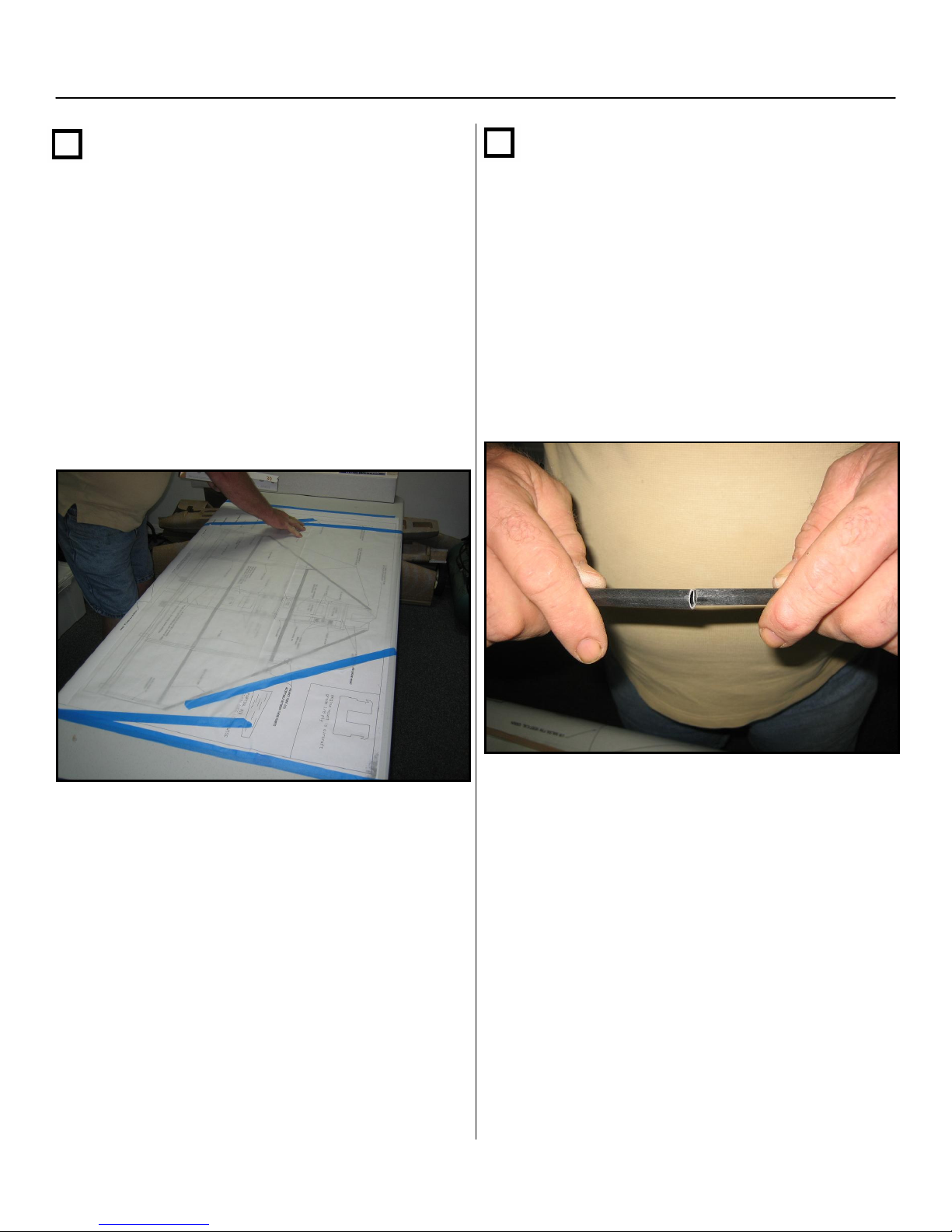
Step 1
Locate all parts listed in materials list, and
take inventory of all parts. This will help you
familiarize yourself with the various
components.
Lay your print out on large flat surface ( the
larger and flatter the better). Cover your
plans with either parchment paper or wax
paper and tape them down to secure to your
work surface.
Step 2
Assemble the rear spar by locating the tubes
labeled “Rear Spar” and “Spar extenders”.
Insert the spar extenders into each end of the
rear spar. You may have to lightly sand the
spar extenders so that they go into the rear
spar with a moderate amount of force, but
first try the opposite end of the spar extender
tube to see which end fits the best.
8
Page 9
Section 1: Framing of the Airframe – Cont.
Step 3
Lay the assembled spar on the print to see
how far the tubes should fit into one another.
Adjust both sides so the center main spar is
centered on the print and the end tubes
extend to the correct length shown on the
print (be as precise as possible when
matching the print through all the steps).
Step 4
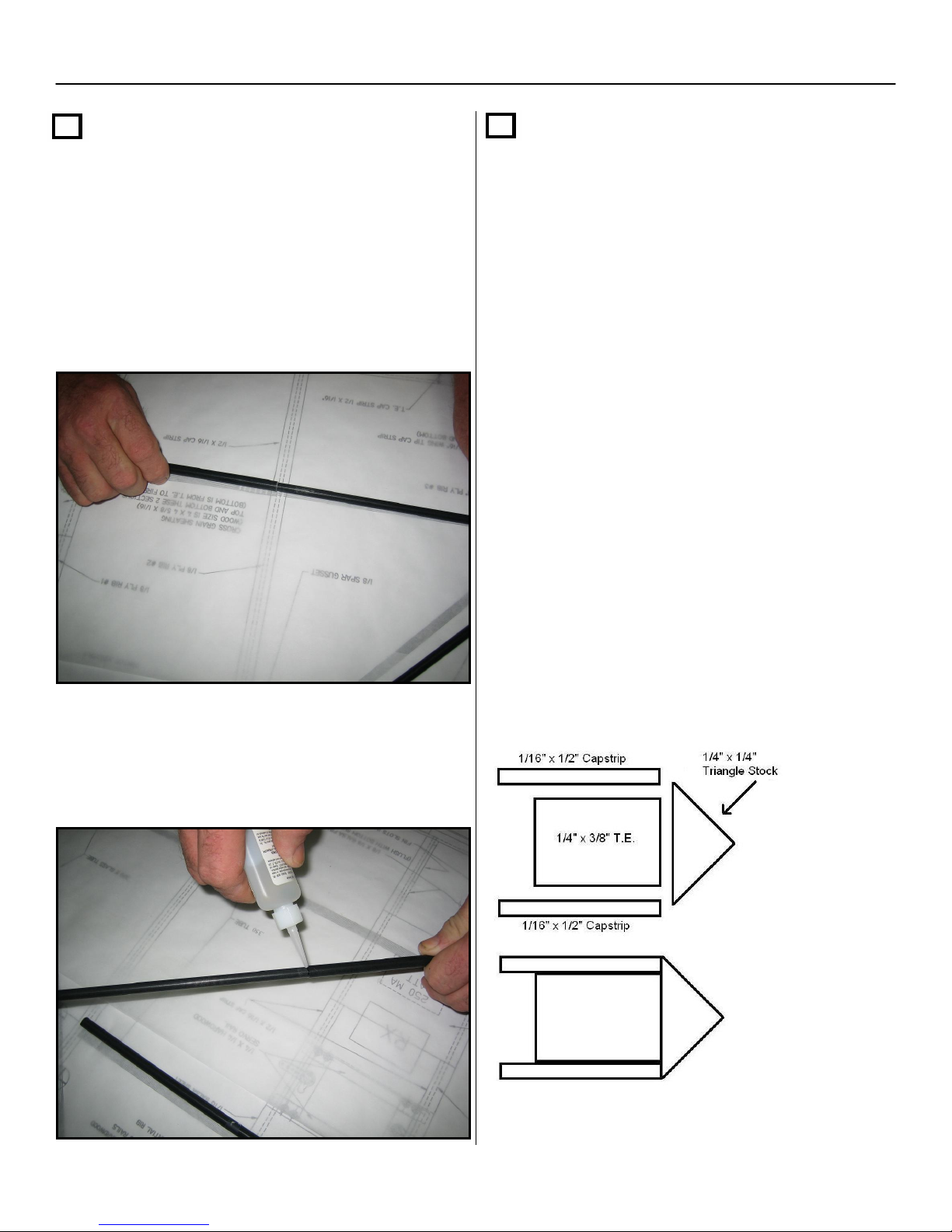
Find the ¼” x 3/8” x 36” balsa stick trailing
edge (T.E) and cut it the same length as
shown on the plan.
Find one of the ¼” x ¼” x 36” triangle stock,
and also cut it to match the trailing edge you
just cut. Center the triangle stock on the ¼”
side of the ¼” x 3/8” T.E. Glue the triangle
stock to the ¼” side with thick CA.
Next, find two 1/16” x ½” cap strips that seem
to be the stiffest from the wood supplied with
the kit. Cut them to match the length shown
on the plans.
When the rear spar matches the print (tube
engagement and overall length), apply a drop
of thin C.A. on each joint.
NOTE: Do not glue the T.E. cap strips
beyond the #2 ribs until the wing tips are
installed in step #16.
Examine the drawing below to ensure proper
assembly of the T.E assembly.
When you are done assembling the T.E.,
set it aside until step 10.
9
Page 10
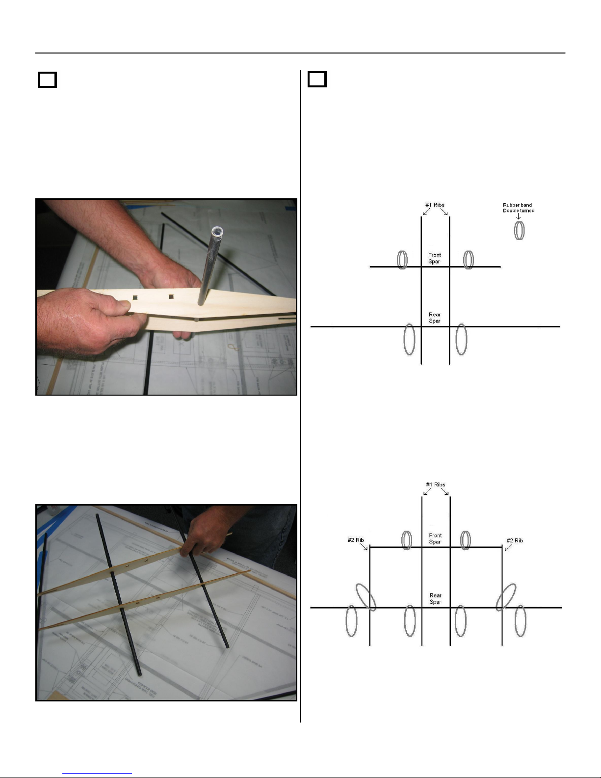
Section 1: Framing of the Airframe – Cont.
Step 5
Take the two center ribs (rib #1) and locate
the square 1/4 x 1/4 servo rail holes. Note:
the square holes are closest to the top
side of the airfoil.
Step 6
Install one #19 rubber band (included) over
each rear spar half and one rubber band
over each forward spar half, as shown
below. Note: you will need to double turn
the rubber bands that go over the forward
spar halves.
Next, hand slide the front and rear spars
onto the center ribs (#1 ribs). Align the ribs
and position them as shown on the print.
Do not glue anything yet!!!
Next, slide the #2 ribs over the rear spar.
Add one more rubber band to each side of
the rear spar and one diagonally around the
rear spar and rib #2, as shown below.
Section 1: Framing of the Airframe – Cont.
10
Page 11
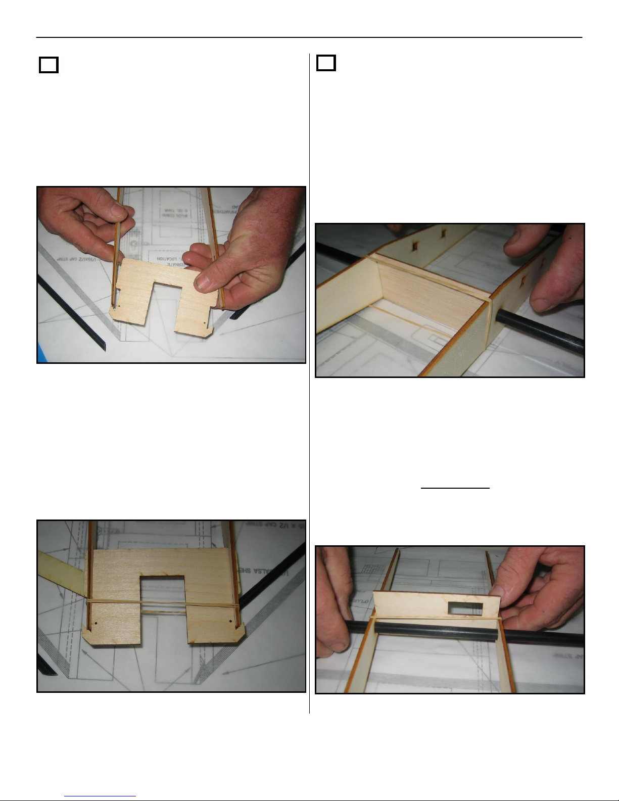
Step 7
Place the engine mount in between the two
#1 ribs. You will first have to insert the front
part of the #1 ribs into the front part of the
mount in order to clear the leading edge
locking tabs.
Step 8
Take the 1/16” x 1-3/4” x 4” balsa fuel tank
c
ompartment rear bulkhead
vertically against the front of the front spar
between the #1 ribs. Place a #19 rubber
band around the ribs to secure the bulkhead
as a spacer. You may have to double the
turns on the rubber band in order to achieve
a strong hold. Do not glue yet!!!
and lay it
Next, temporarily secure the mount into
position by using one #19 rubber band
around it and the #1 ribs. You will have to
double the turns on the rubber band in order
to achieve a strong hold
Next take the 1/8” x 3-7/8” x 1-3/4” plywood
switch plate and place it vertically on the
rear spar between the #1 ribs. Place a large
rubber band around the ribs to secure the
switch plate as a temporary spacer.
NOTE: Do not glue this plate to the ribs
or rear spar !!!
11
Page 12
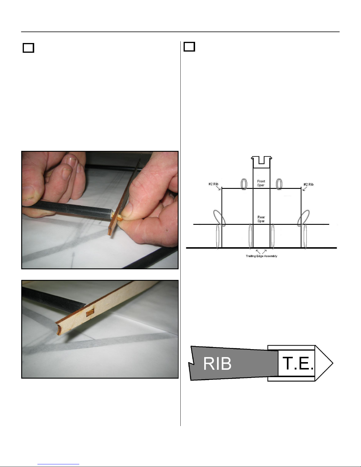
Section 1: Framing of the Airframe – Cont.
Step 9
Center the forward spar with the alignment
hole in the #2 rib (centered top and bottom),
and insert one of the 1/8” x ¼” x ½”
plywood spar end / rib locking tabs through
the rib and into the spar. Put a few drops of
thin CA where it is connected. Repeat on
the opposite side.
Step 10
Take the trailing edge assembly from step 4
of this section and slide it through the four
#19 rubber bands that are on the rear spar.
Place the rubber bands so they are
alongside the #1 ribs and on both sides of
the #2 ribs, as shown below. Line up all
spars and ribs to match the print as
precisely as possible.
When in place, put a drop of thin CA at
each rib to tack in place.
Note: the trailing edge of the ribs should
self center in between the 1/16” cap strips
on the T.E assembly.
12
Page 13
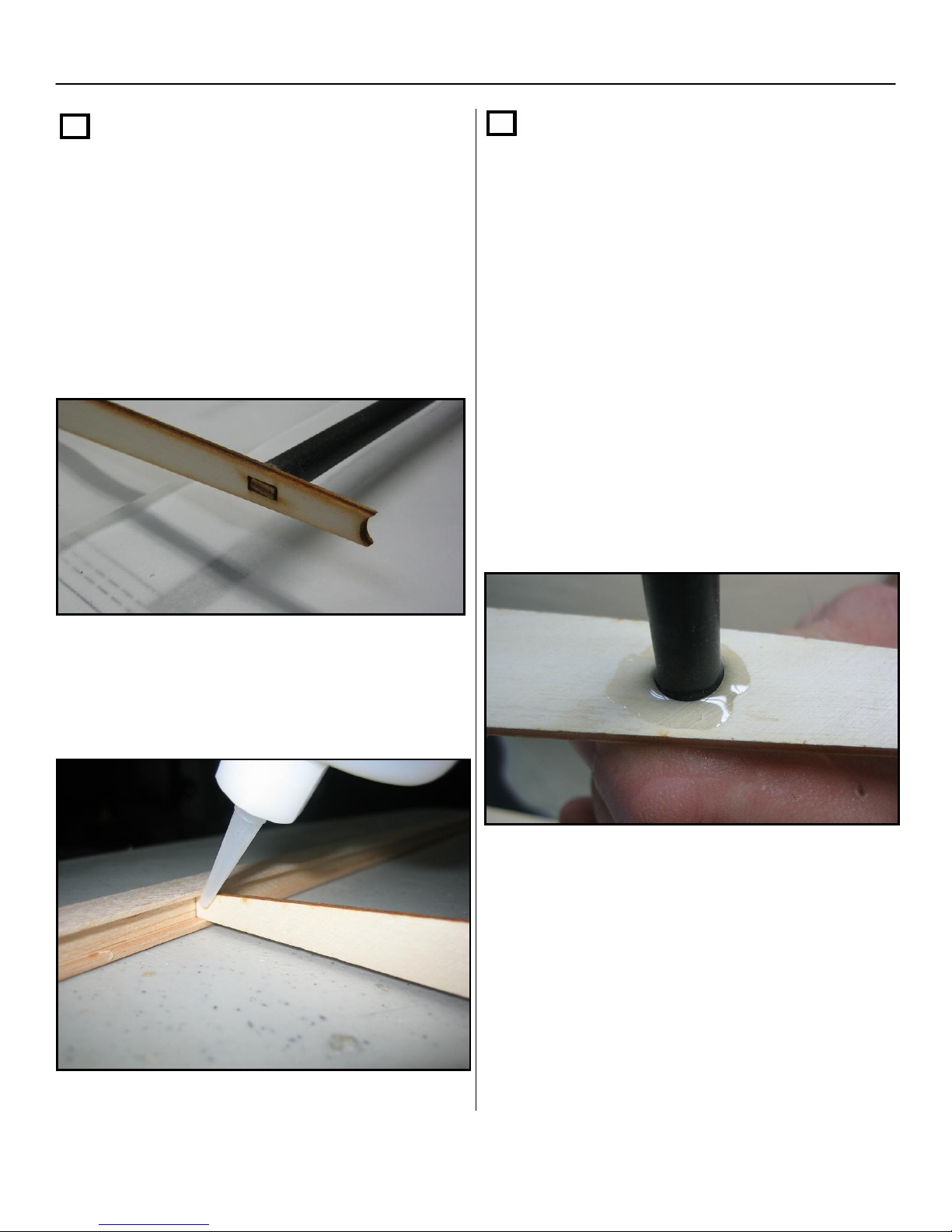
Section 1: Framing of the Airframe – Cont.
Step 11
Square up and center the #3 rib on the T.E
and the rear spar extender. Next, insert the
wood tab through the #3 rib into the rear
spar extender. When everything is aligned
and square, first glue with thin CA and then
with thick CA. Repeat this step for the
opposite side.
Step 12
NOTE: be careful not to glue the
temporary spacers at the spars or the
rubber bands.
Make sure the fuel tank compartment rear
bulkhead is square and then first glue with
thin CA then with thick CA.
Next, glue the main ribs to both the forward
and rear spars first using thin CA, then fill in
around the spars with thick CA.
Make sure that everything lines up on the
print and finish gluing all ribs to the trailing
edge.
You can now cut the four rubber bands that
hold the T.E. assembly. Keep the remaining
rubber bands on the airframe, since you will
need these to install the leading edges of the
aircraft.
13
Page 14
Section 1: Framing of the Airframe – Cont.
Step 13
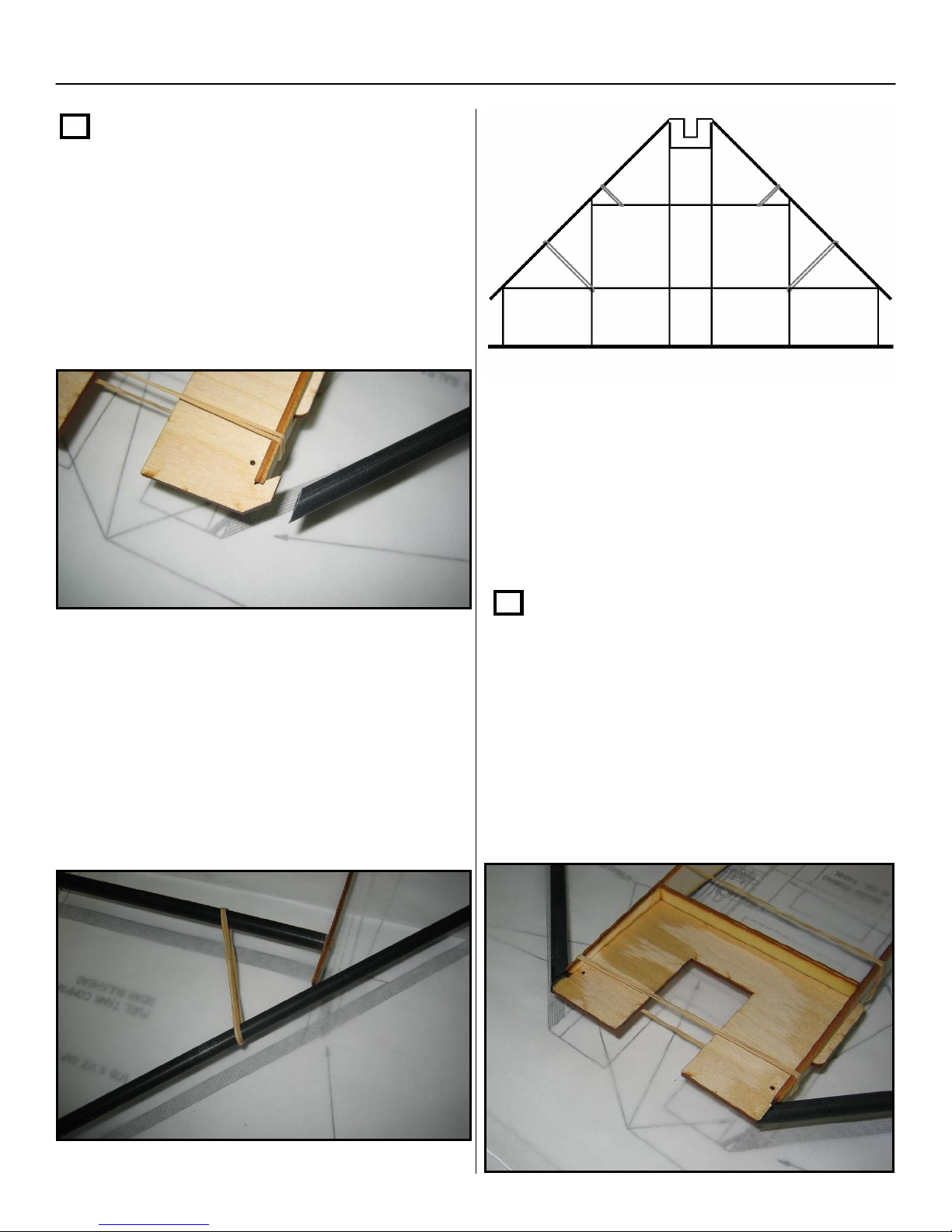
Next you will be installing the leading edges
on the airframe. Find the two tubes labeled
“L.E. Tubes” and slide each one through the
double rubber bands attached to the forward
spar halves. Make sure the 45 degree cuts
are facing the motor mount.
Once you have both leading edges aligned
and sitting on both the #2 and #3 ribs, place
a drop of thick CA on both sides of the #2
and #3 ribs at the leading edge. The square
end of the L.E. tube will extend beyond the
wing tips. Leave this extra length for now.
Insert the L.E. tube into the angled motor
mount tabs and rest the tube on both the #2
and #3 ribs.
Note you may have to slide the rubber band
back in order to increase the tension
between the L.E. and the front spar.
Step 14
Next, Locate the
plywood firewall and center it between the
#1 ribs and the motor mount plate. Apply
glue
on both sides, where the firewall
intersects the #1 ribs and where it touches
the motor mount, with both thin and then
thick CA. Then, cut the rubber bands holding
the motor mount.
1/8” x ¾” x 3-7/8”
14
Page 15
Section 1: Framing of the Airframe – Cont.
Step 15
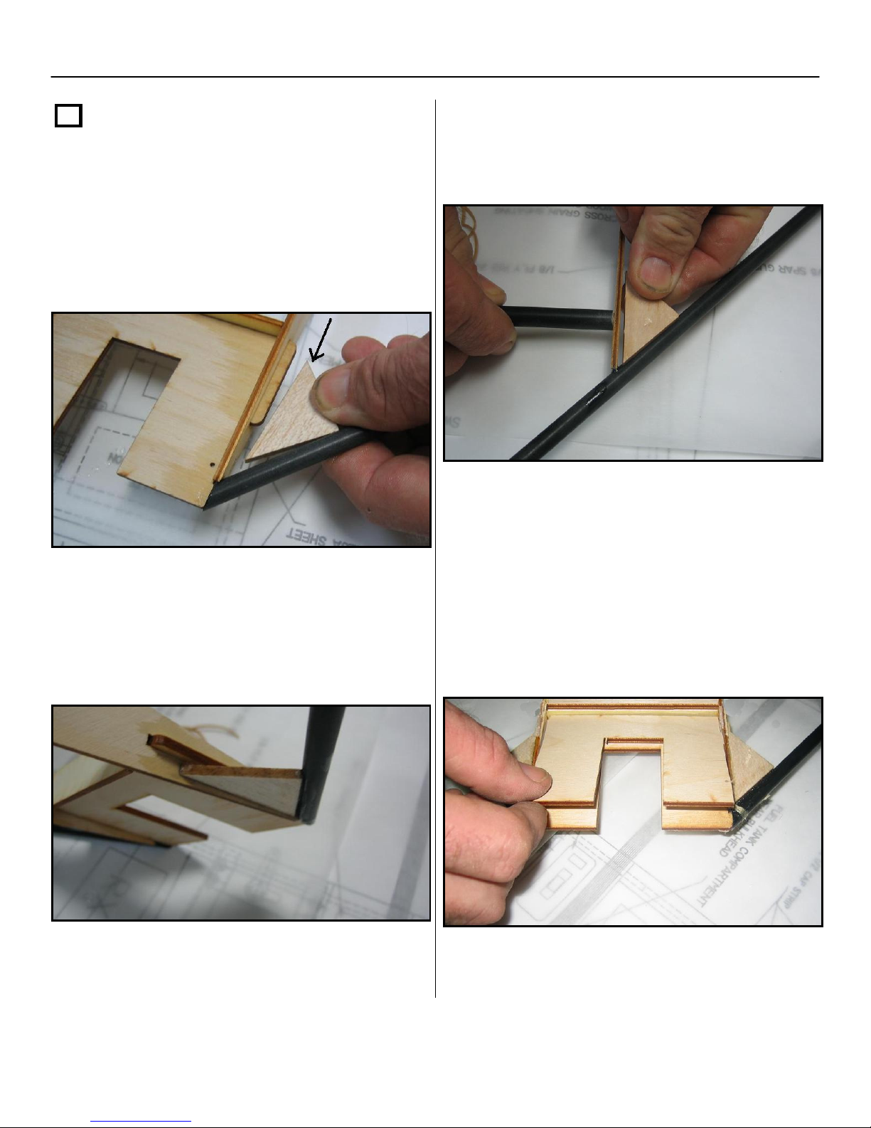
Locate the triangle gussets from the parts
bag. The first ones are installed behind the
leading edge at the motor mount. Glue
them in with thick CA in the location shown
on the plans.
Next glue the triangle gussets, that are
positioned behind the L.E. and on the outside
of the #2 ribs, with thick CA.
NOTE: make sure you glue both the top
and bottom sides of gussets where they
Note: the forward gusset should be
installed underneath the protruding tab from
the motor mount while the airframe is in the
upright position.
connect to the leading edge and ribs.
Now add the motor mount doubler plate to
the bottom of the motor mount. Glue in using
thick CA all around the bottom of the motor
mount and clamp tight until the glue dries.
15
Page 16
Section 1: Framing of the Airframe – Cont.
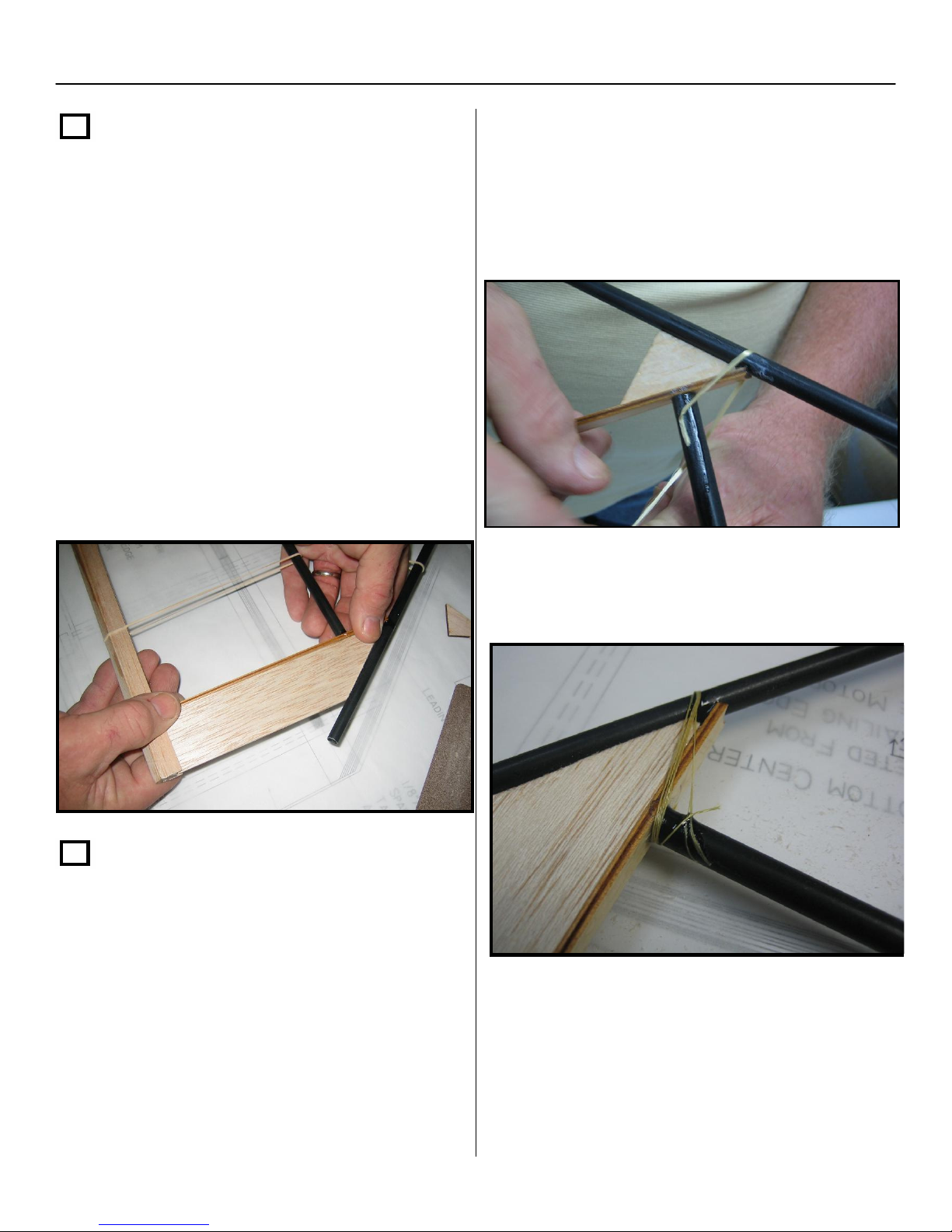
1/2” elevon
Step 16
Locate the two p
stock / balsa wing tips, with
recut 1/4”x1-
the 38 degree
angle on one end, and place the square end
between the TE cap strips with the 38
degree angle cupped into the rear side of
the leading edge on the outside of rib #3.
Glue in place first with thin CA and then add
thick CA where the balsa meets the
backside of the L.E. Repeat this step for
both sides. NOTE: Do not glue the 1/16 x
½ “cap strips on the trailing edge
assembly yet!
Place a drop of thin CA on the spar tube and
lay the tip of the Kevlar thread in the glue
drop and allow it to dry. This will hold the
Kevlar in place while you wrap the thread
around the ribs and L.E. and spar.
Next, wrap 5 to 6 turns around the rib, L.E.
Step 17
Locate the Kevlar thread in the parts bag.
Following the illustrations on the print, first
wrap the #2 and # 3 ribs where they
intersect the L.E. Make sure you reference
the print first before starting, to ensure that
you will be installing the Kevlar at the proper
angles.
and spar, while holding the Kevlar thread
tight.
Once wrapped, soak the entire Kevlar thread
with thin CA. Repeat this step for all four
points where the ribs and L.E. intersect, as
shown on the print. NOTE: You can now
cut the four rubber bands that hold the
leading edge tubes.
16
Page 17
Section 1: Framing of the Airframe – Cont.
Step 17 – Cont.
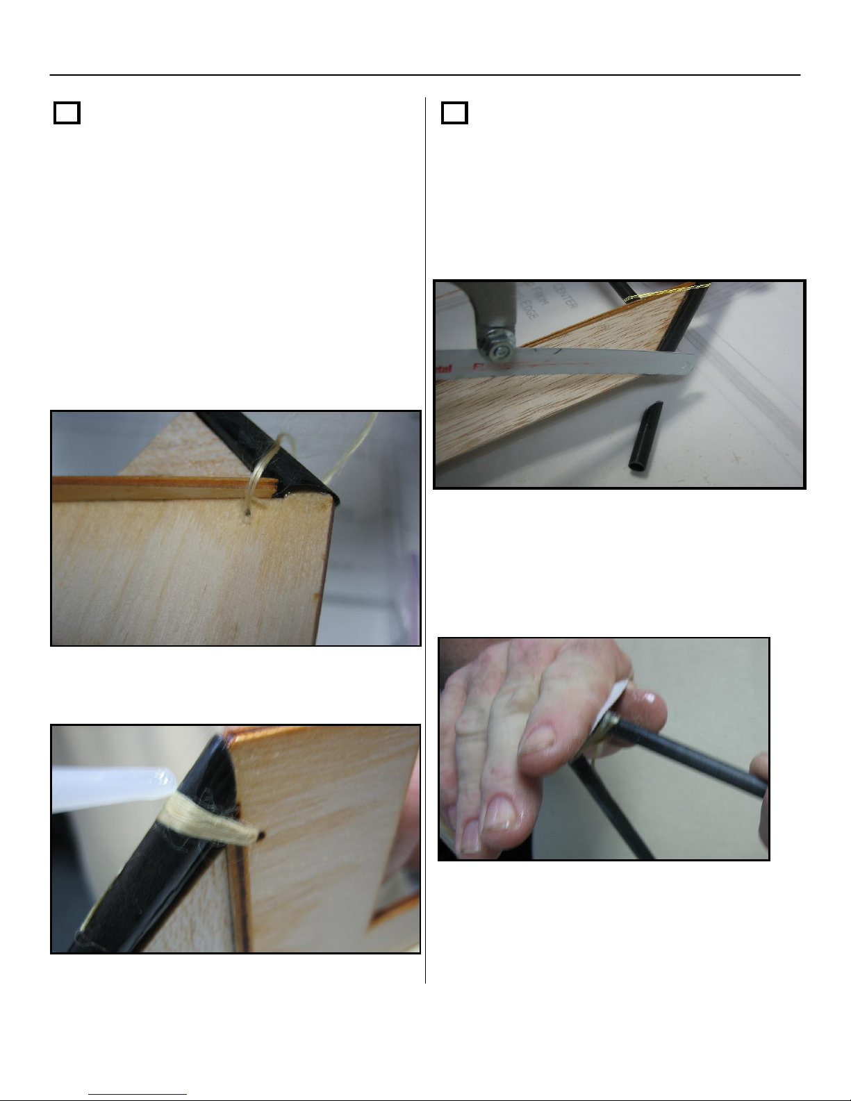
Next, thread the Kevlar through one of the
small laser cut holes found on the motor
mount and wrap it around the leading edge
and motor mount 5 or 6 times while
reinserting it through the laser cut hole. Glue
it in with thin CA.
NOTE: you may have to re-drill the holes
since the laser cut hole may have been filled
in with glue from step 15
Step 18
Trim the .300 E glass tube flush with the
wing tip (Hack saw, razor saw,9+ or band
saw works well for this; a fine file will also do
the job).
Repeat this for both sides of the motor
mount.
After cutting off the extra tubing from both
L.E. tubes, sand the ends down flush to the
1/4”x1-1/2” elevon stock / balsa wing
tips.
17
Page 18
Section 1: Framing of the Airframe – Cont.
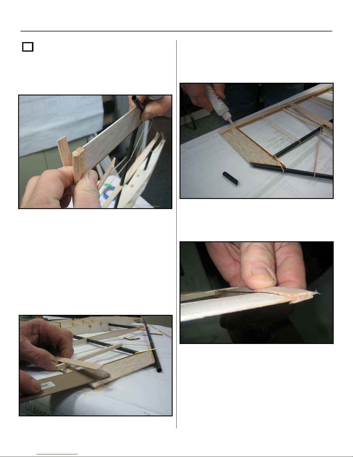
Step 19
Now separate the unglued portions of the
cap strips at the ends of the T.E. assembly.
When you have finished shaping both sides
of the T.E., glue the cap strips down to the
tapered T.E assembly on both sides of the
airframe.
Next, place a small piece of balsa stock or a
pencil in between the cap strip and the ¼” x
3/8” T.E. stock to keep the cap strip
elevated. Sand the trailing edge to match
the taper of the wing tip balsa stock. Repeat
the sanding and shaping of the T.E. for both
top and bottom of the T.E assembly on both
sides of the airframe.
Your cap strips and trailing edge should look
like the photo below when completed.
18
Page 19
Section 1: Framing of the Airframe – Cont.
Step 20
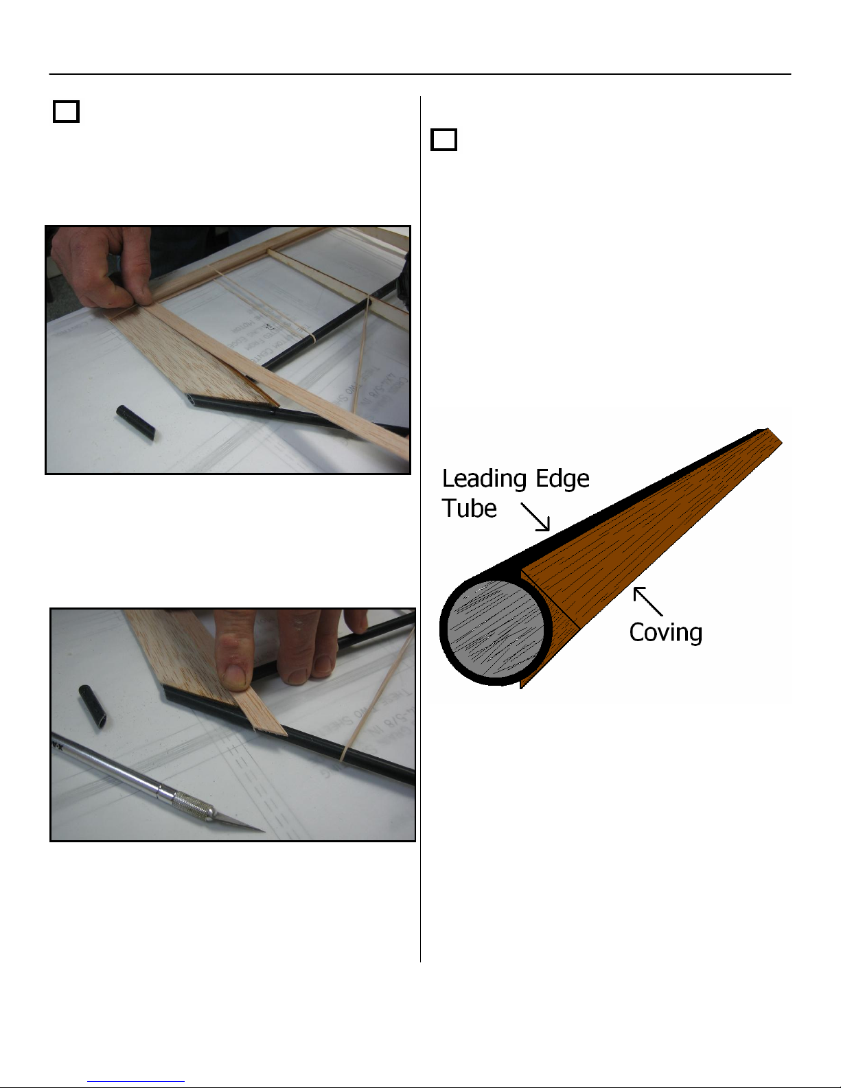
Apply cap strips to both top and bottom of the
#3 ribs on both sides of the airframe.
Step 21
Next, locate the leading edge hardwood
coving stock and apply one piece to each of
leading edge tubes with thick CA. Start at
the motor mount and apply rearward. Make
sure to leave a little at the motor mount so
you can cut and sand to shape later.
Note: Take care to apply the coving as strait
as you can on the L.E. tubes.
Trim the cap strip with a hobby knife or
scissors to match the angle of the L.E. tube.
19
Page 20
Section 1: Framing of the Airframe – Cont.
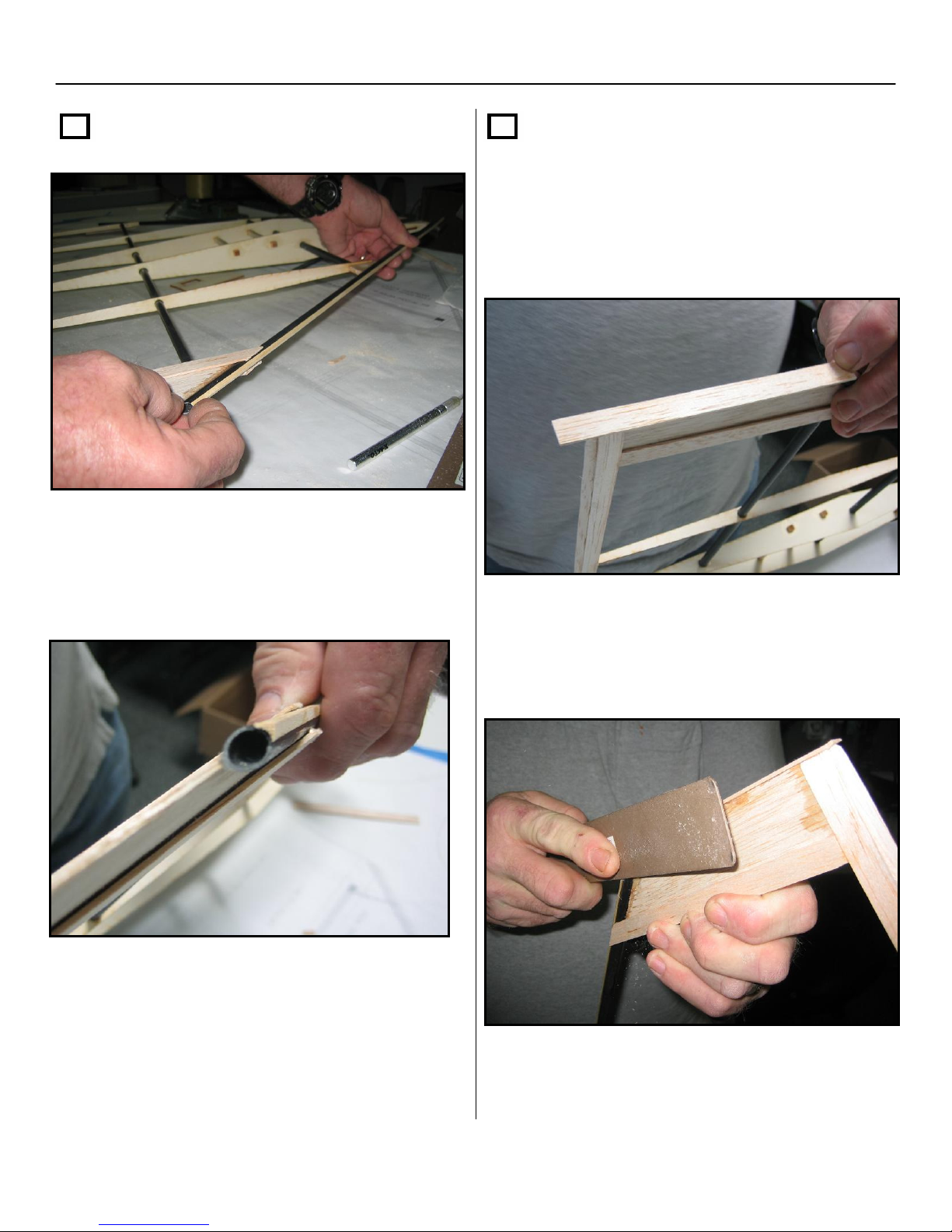
Step 21 – Cont.
Cut each piece of coving stock flush with the
tip of the L.E. tubes and the motor mount,
then sand lightly.
Step 22
Now cap strip the outer edge of both the
balsa wing tips from the L.E tubes back to
the T.E. Leave a little extra at both ends
for shaping.
When dry, sand down the end cap strip so it
tapers from the L.E. tube back to the T.E
assembly.
20
Page 21
Section 1: Framing of the Airframe – Cont.
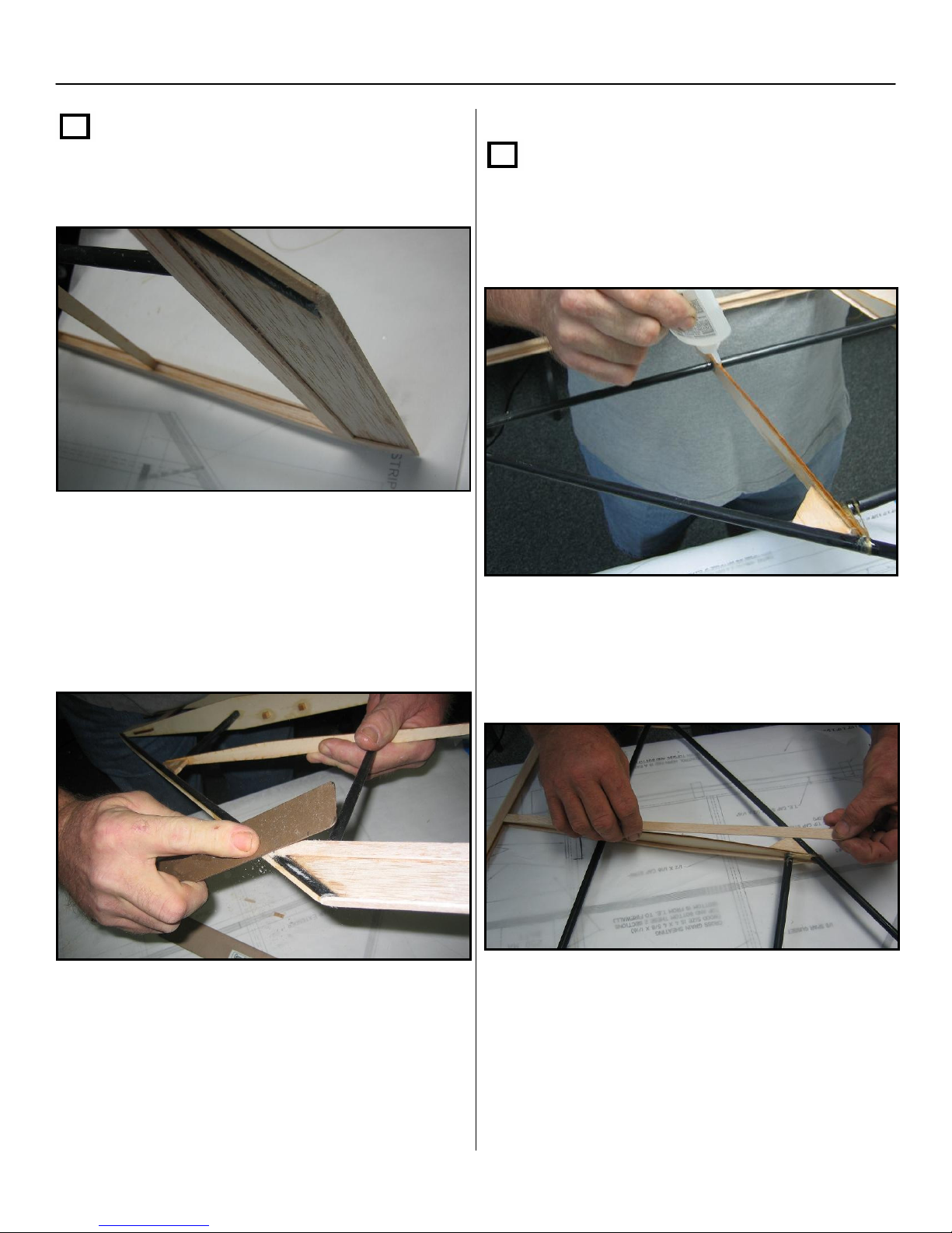
Step 22 – Cont.
The taper should be strait and consistent
towards the T.E.
Next, sand the cap strip over the #3 rib so it
flares around the L.E tube assembly. NOTE:
Step 23
Install a 1/16” x ½” cap strip to the top and
bottom of the #2 ribs using thick CA.
be careful to not sand through the Kevlar
thread that is wrapped around the L.E and
the #3 rib.
When sanding is complete, fill any gaps with
thick CA.
When you have both the top and bottom cap
strips installed on the #2 ribs, cut the cap
strip at the same angle, but a little longer
than the L.E tubes.
Then, sand and fill the gaps at the L.E. the
same way as shown for the #3 ribs in step
22.
21
Page 22
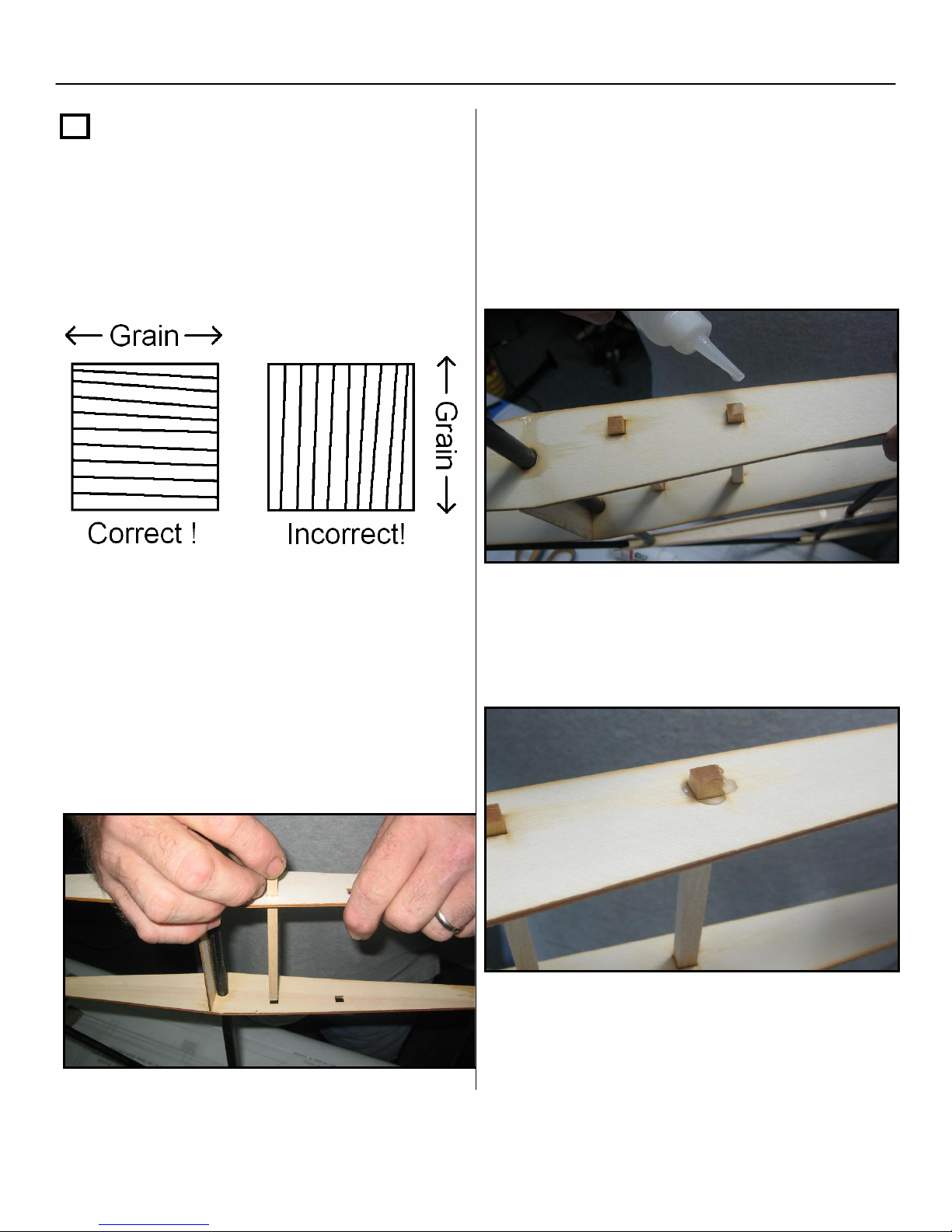
Section 1: Framing of the Airframe – Cont.
Step 24
NOTE: when installing the hardwood rails,
pay close attention to the direction of the
grain by looking at the end of the rails before
inserting them into the ribs. The grain should
go fore and aft and NOT up and down.
At this point, install your servo rails.
Take the
servo rails
square holes. Check to make sure your
servos fit. If your servos do not fit, make an
¼” x ¼” x 4-3/8” hardwood
and slide them through the
Glue the servo rails in first using a drop of
thin CA between each servo rail and each #1
rib. Note: Center the rails so you leave
approximately ¼” sticking out on the outside
of both ribs.
When you have finished applying the thin
CA, apply a bead of thick CA around the
rails on both sides of each rib.
adjustment on the rear hole at this point.
The output shafts of the servos should be
completely above the ribs and sheeting.
22
Page 23
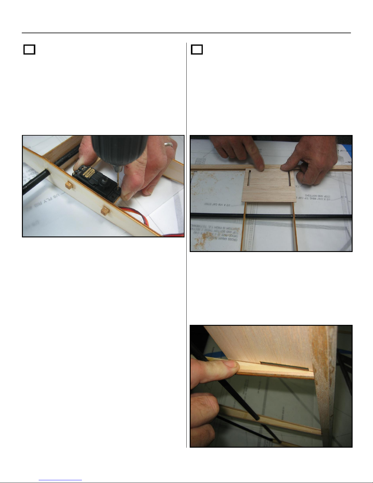
Section 1: Framing of the Airframe – Cont.
Step 24 – cont.
Once you have both servo rails glued in, you
will need to pre-drill your servo mounting
holes. Note: Position the servos so you leave
approximately 1/16” between the #1 rib and
the side of the servo.
Step 25
Next find the
sheet with precut slots and glue it at the
trailing edge of the aircraft on the topside
of the airframe using thick CA.
NOTE: Make sure the slots are at the
T.E and NOT facing the front of the
airframe when installing.
4” x 4-5/8” x 1/16” Balsa
Once you are done with pre-drilling the
servo mounting holes, remove the servos
and set them aside. You will not need them
until section 7.
Next, turn the airframe over (bottom side up)
and locate two of the
fin offset spacers. Align the spacers so
they butt up to the T.E. and are aligned to
the bottom edge on the inside of the #1
ribs. Repeat this step for both spacers.
1/8” x 1/8” x 4” balsa
23
Page 24
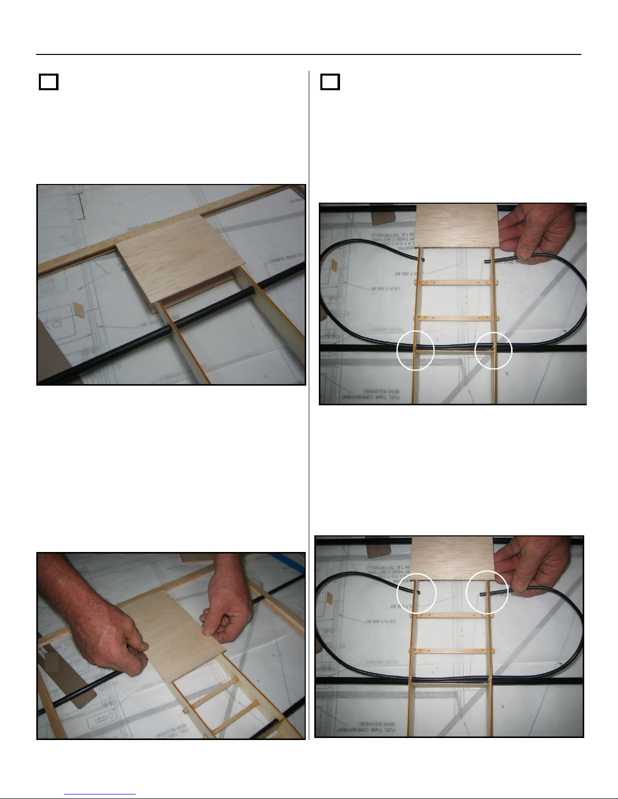
Section 1: Framing of the Airframe – Cont.
Step 25 – cont.
With the airframe bottom side up,
install the
sheeting, beginning at the TE and going
towards the nose, using thick CA.
4” x 4-5/8” x 1/16” balsa
center
Step 26
The antenna tube will be inserted in
the four precut 3/32” holes found on both of
the main ribs. You will need to feed the
antenna tubing through the front holes first.
As shown below.
After applying the second cross grain sheet,
you will need to determine if you will be
using a standard radio receiver or a spread
spectrum receiver.
If you will be using a spread spectrum
receiver you may skip the rest of step 23
and proceed to step 24.
After centering the tubing through the front
holes, insert the remaining portion of tubing
In the rear holes.
Remember: the airframe should still be
upside down.
24
Page 25
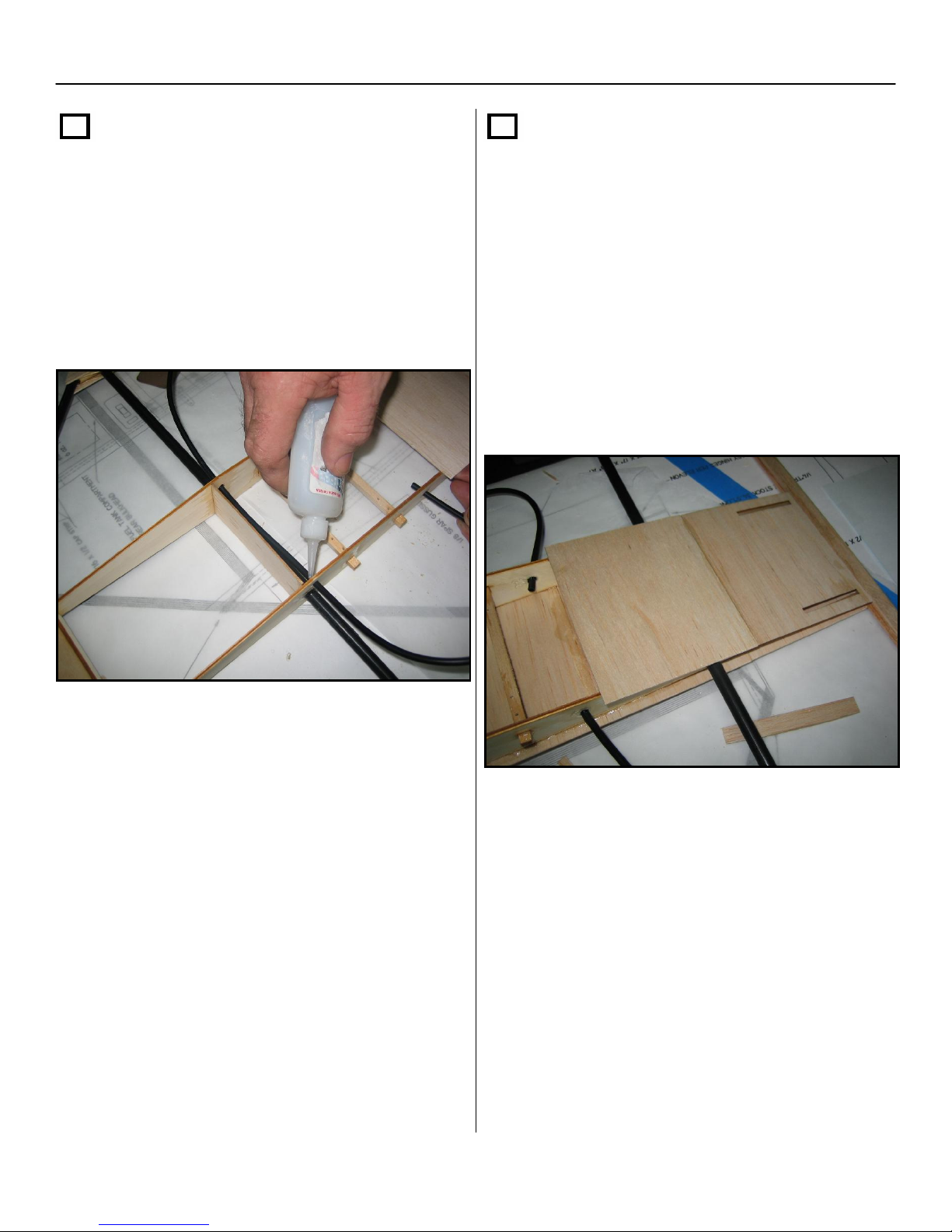
Section 1: Framing of the Airframe – Cont.
Step 26 – cont.
Leave approximately ¼” to ½” of the tubing
protruding through the #1 ribs. Next, glue the
tubing in with thin CA then thick CA, on both
sides of every hole the tubing intersects.
Step 27
Continue to apply the rest of the cross grain
sheeting on the bottom of the airframe. The
last piece should stop at the firewall (it will
have to be trimmed).
Then, turn the airframe over and apply one
more cross grain sheet to the topside of the
airframe, in front of the fin cross grain sheet,
for a total of 8” of sheeting in front of the
trailing edge of the aircraft.
25
Page 26
Section 1: Framing of the Airframe – Cont.
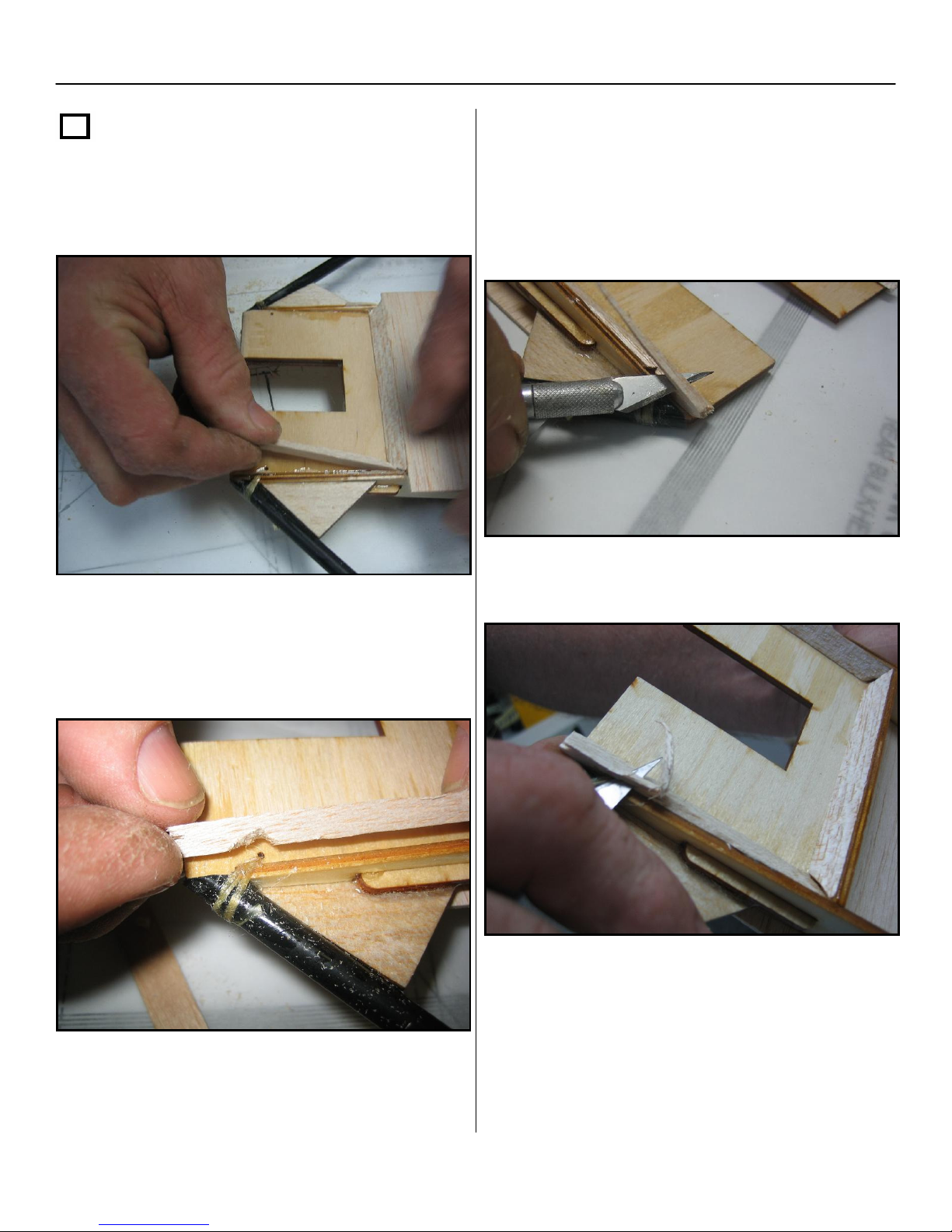
Step 28
Next you will cut pieces of ¼” x ¼” triangle
stock to fit on the inside area of the motor
mount plate.
With a hobby knife, trim the triangle stock to
match the #1 rib profile.
Miter your corners at 45 deg. angles for best
fit. You may have to notch the triangle stock
to clear the Kevlar thread that is wrapped
around the motor mount plate and the L.E.
When you are done trimming the triangle
stock for both the top and bottom of the
Repeat this procedure for both the top and
bottom of the motor mount plate.
26
motor mount, lightly sand the triangle stock
to match the ribs and firewall.
Page 27
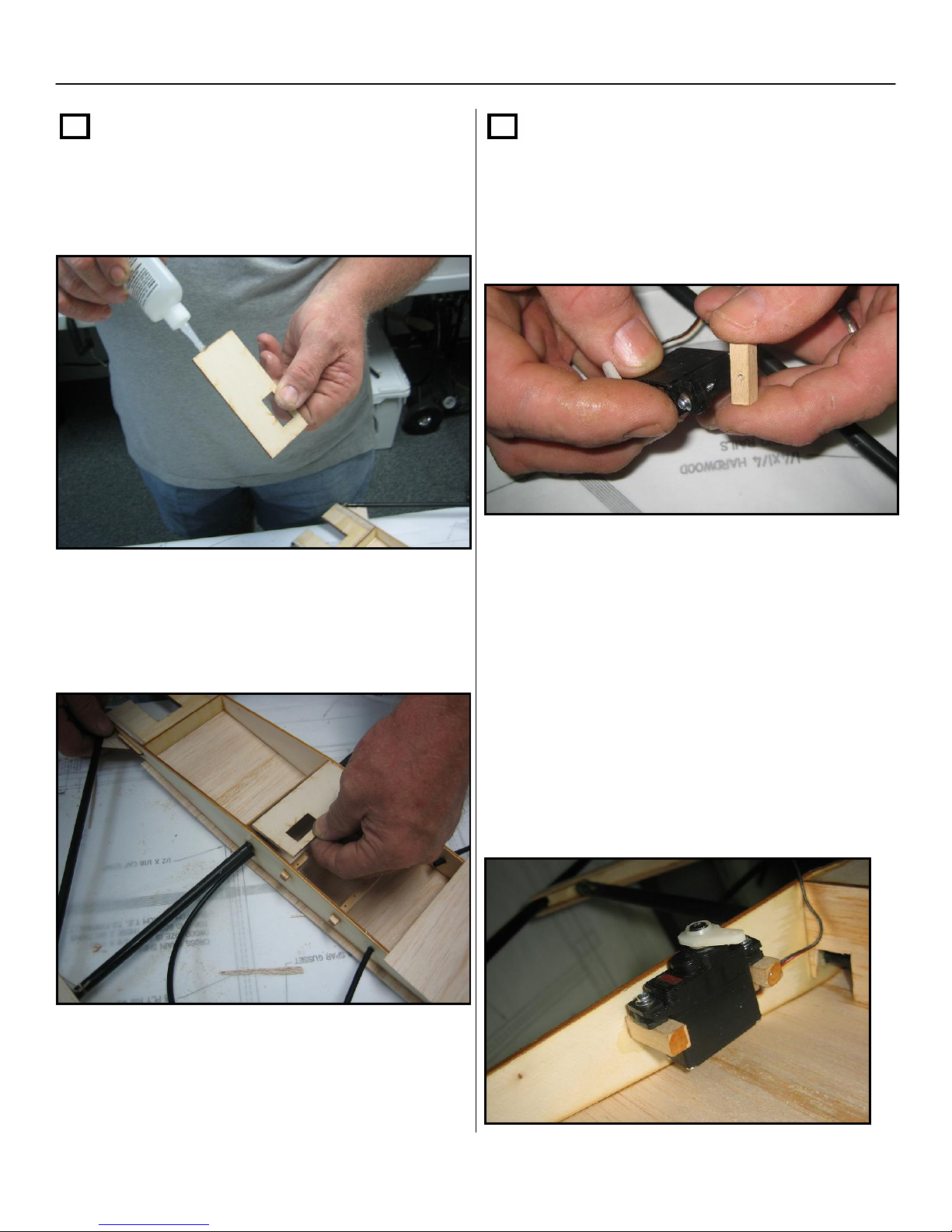
Section 1: Framing of the Airframe – Cont.
Step 29
Locate the 1/8” x 3-7/8” x 1-3/4” plywood
switch plate and apply thick CA to the sides
and front part of the switch plate.
Refer to plans for proper orientation and glue
the switch plate so it is even with the side of
the ribs.
Step 30
Locate the two ¼” x ¼” x 7/8”
hardwood throttle servo rails. Pre-mount the
throttle servo to the short servo rails (this will
be used to set the spacing between the #1 rib
and the partial rib).
Next, determine which side of the fuel tank
compartment your throttle servo will need to
be positioned by which side of your motor the
carburetor linkage is located.
Place a drop of thick CA on each end of the
hardwood servo mount rails and install the
throttle servo as far forward as possible.
There should be enough room for the servo
arm to clear the top of the ribs and future cap
strips.
27
Page 28
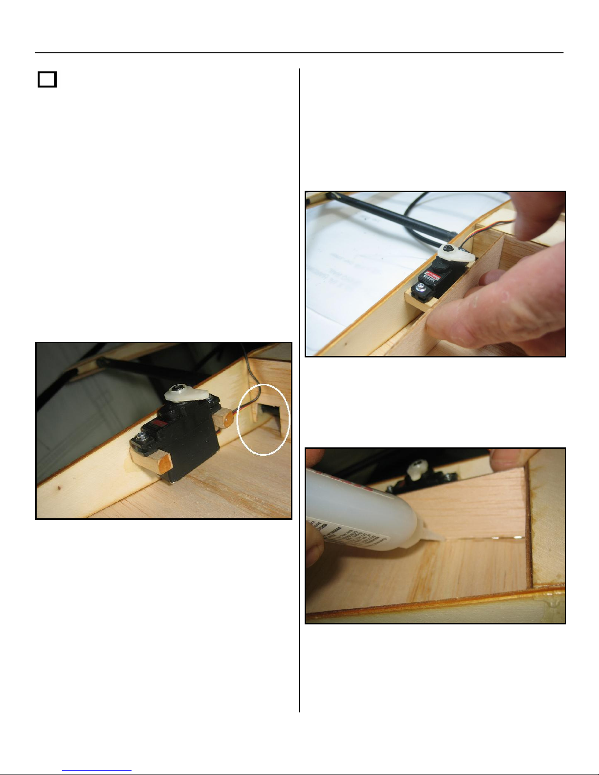
Section 1: Framing of the Airframe – Cont.
Step 30 – cont.
Locate the
it between the firewall and the fuel tank rear
Once you have determined which side the
bulk head, while pressing it up against the
throttle servo will be mounted, cut a small ¼”
throttle servo and hardwood servo mount
x ¼” hole in the 1/16” bulkhead to allow for
rails that have thick CA on them.
your throttle servo lead to be passed
rearward into the radio / elevon servo
compartment.
NOTE: Make sure your hole does not
reach over more than 7/8” from the rib.
Place a drop of thick CA on the end of each
hardwood servo mount rail.
1/16” balsa partial rib and i
nsert
Finish gluing the partial rib in, using thick
CA.
28
When the glue is dry, remove the throttle
servo and set it aside until Section 5.
Page 29
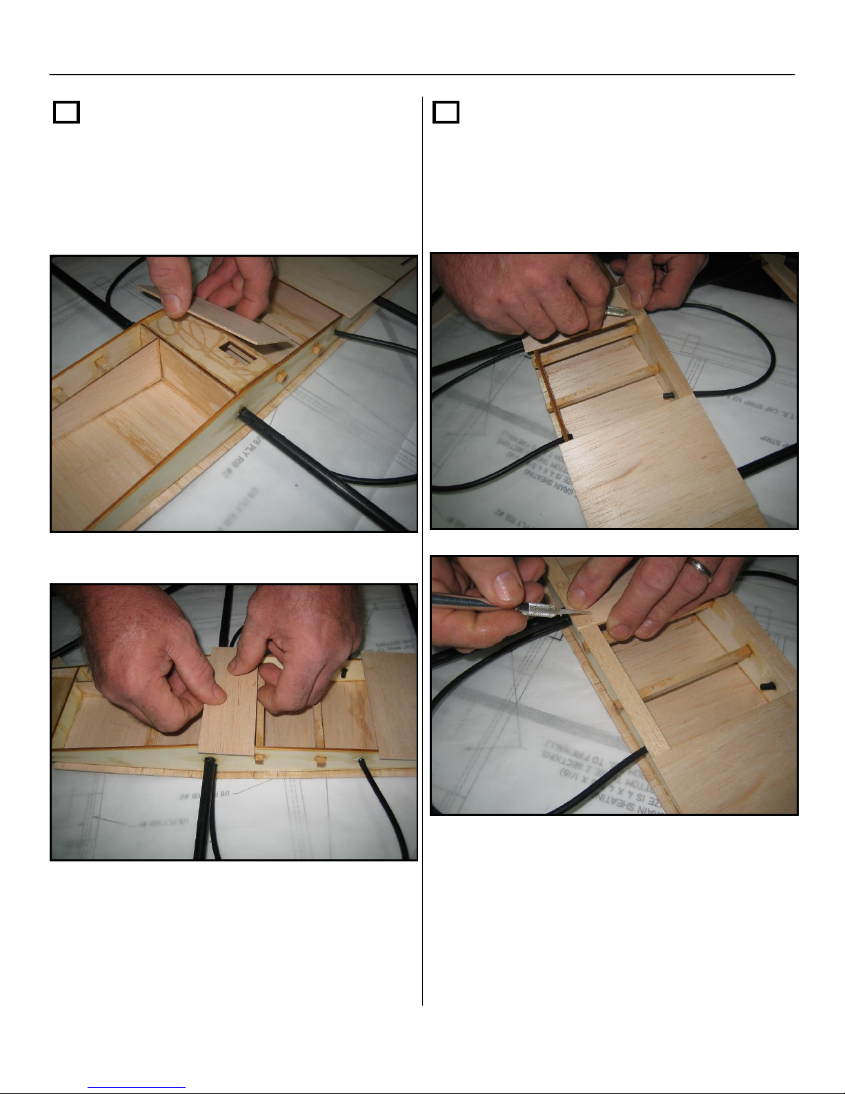
Section 1: Framing of the Airframe – Cont.
Step 31
Locate a piece of
cross grain sheeting and cut it to match the
plywood switch plate. Then glue it in using
thick CA.
4” x 4-5/8” x 1/16” balsa
Step 32
Cut-to-fit two 1/16” x ½” cap strips to fit
over both #1 ribs, between the newly
covered switch plate and the cross grain
sheet where the elevon servos are mounted.
29
Page 30
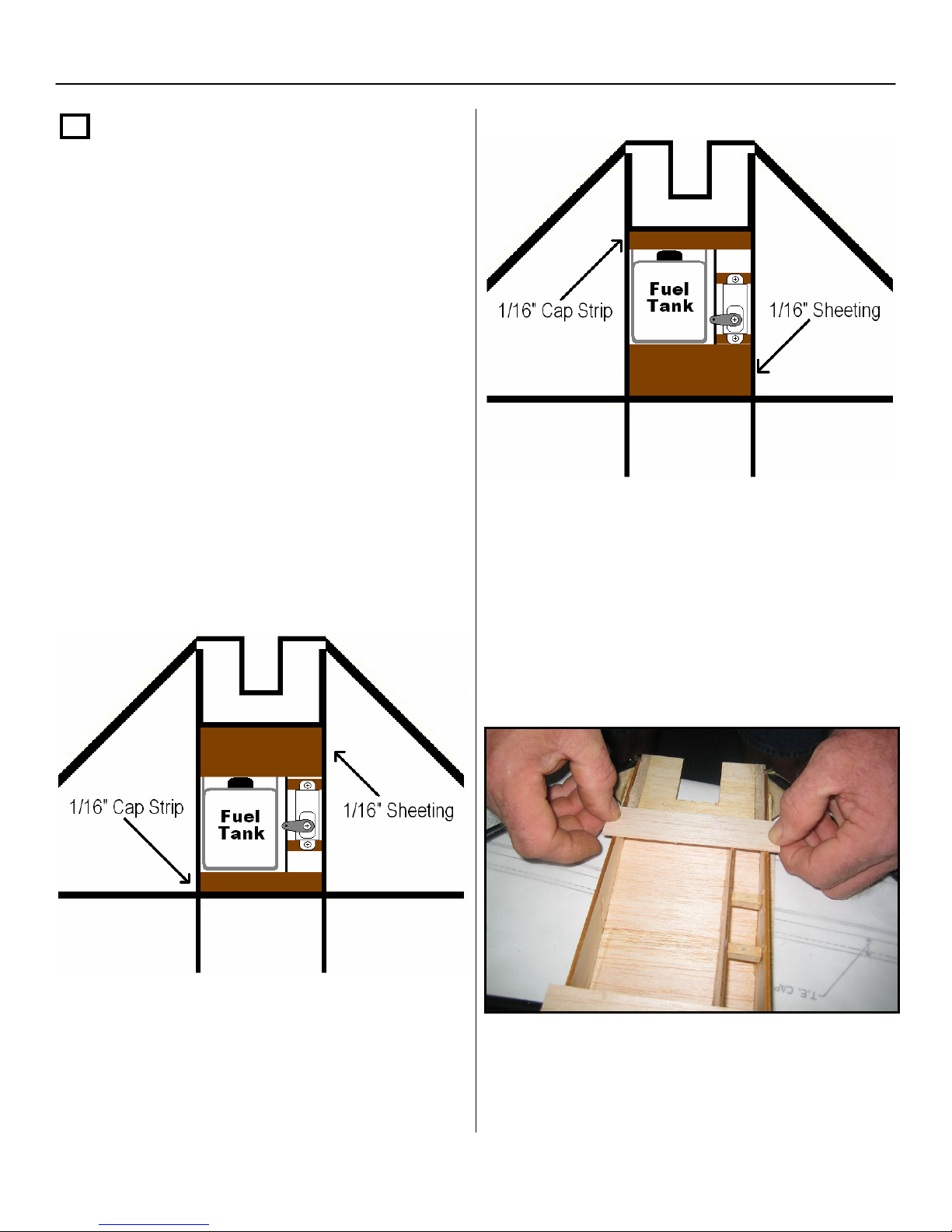
Section 1: Framing of the Airframe – Cont.
Step 32 – cont.
NOTE:!!!
The next step is determined by what size
engine you will be using. If your engine is
a .28 or smaller you will place the fuel
tank against the rear bulkhead of the fuel
compartment. If your engine is a .30 or
larger you will position the fuel tank up
against the plywood fire wall. This
assembly manual and the plans show the
assembly for a .30 or larger engine.
If you are installing a .28 or smaller, you
will reverse the 1/16” x ½” x 4-5/8”cap
strip and the 1/16” x 2” x 4-5/8” sheeting
as shown below.
.30 C.I. or Larger Engine
Install the 1/16” cap strip across the main
ribs, at the plywood firewall, with thick CA.
.28 C.I. or Smaller Engine
This cap strip will also help lock in the fuel
tank when the fuel tank is installed.
30
Page 31
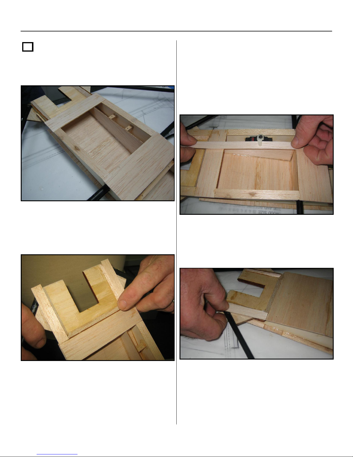
Section 1: Framing of the Airframe – Cont.
Step 32 – cont.
Next apply 1/16” cap strips to both #1 ribs
between the switch plate and firewall.
Add another piece of 1/16” cap strip to the
partial rib in the fuel tank compartment.
Remember to apply all cap strips with thick
CA.
Make sure to check that you have clearance
for the throttle servo arm.
Apply two more cap strip pieces to the #1
ribs in front of the firewall leading up to the
front of the motor mount.
Cut the scrap 1/16” x 4-5/8” to fit the throttle
servo and fuel tank area.
Turn the airframe over and apply the 1/16”
cap strips to the front of the #1 ribs at the
motor mount plate.
31
Page 32
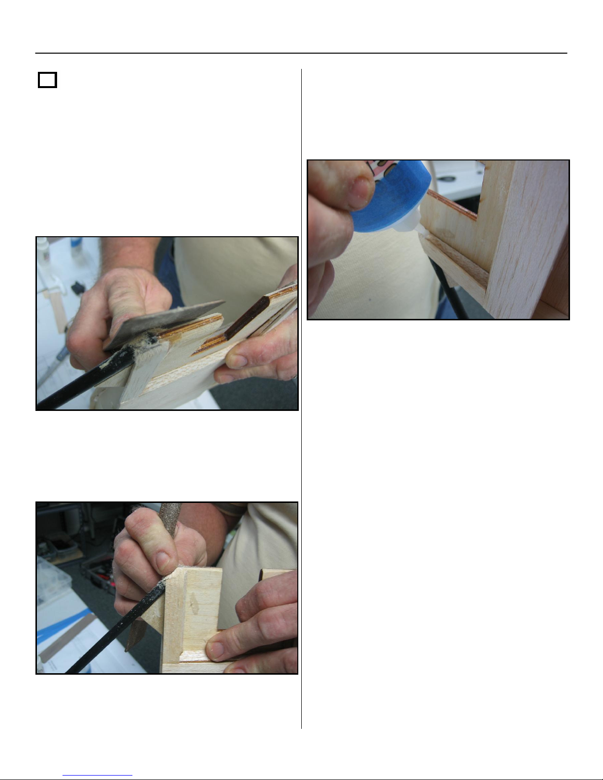
Section 1: Framing of the Airframe – Cont.
Step 32 – cont.
Sand all the cap strips at the LE, and any
rough edges, being careful not to sand
through the Kevlar thread.
NOTE: you can also at this time, taper the
motor mount and doubler by sanding them
to a taper at the L.E of the motor mount.
Also, don’t forget to seal any spaces found
around the cap strip and the motor mount/
firewall area.
Also, fill any holes or pockets around the
engine mount and LE with thick CA or
sawdust and CA.
Lightly sand all wood surfaces and wipe the
airframe clean. Set the airframe aside and
proceed to Section 2.
32
Page 33
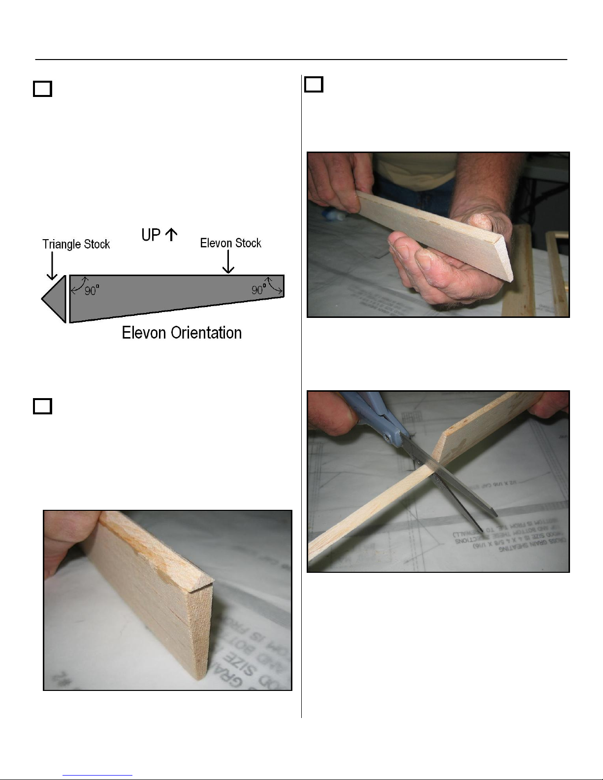
Section 2: Elevon Construction
Note: you can trim the triangle stock easily
Step 1
Locate the two precut balsa elevons
from the box. Please take note that the
elevon stock is NOT symmetrical.
Make sure to orient both elevons with the 90
deg. corners in the up position as shown
below.
Step 2 – cont.
Glue the triangle stock, first using thick CA
and then applying thin CA
with a pair of scissors or hobby knife.
Step 2
Next, locate a full length of ¼” x ¼” triangle
stock and cut two pieces slightly longer than
each elevon, making sure to leave
approximately 1/8” extra on both ends of the
elevons for later sanding.
33
Page 34
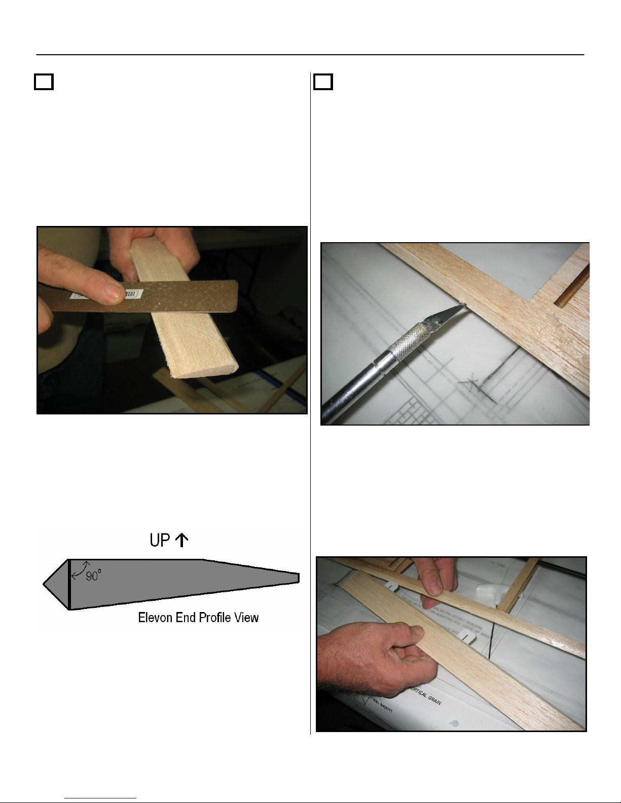
Section 2: Elevon Construction – Cont.
Step 3
Next, sand both ends of the elevon
triangle stock flush with the ends of the
elevon stock. You will also need to taper
the trailing edges of the elevons for
cleaner airflow
Step 4
With the airframe and elevons on the print,
mark all hinge locations on both the elevons
and airframe with a pencil, as indicated on
the plans.
Use your hobby knife or hinge slot tool and
cut the six hinge slots on the trailing edge of
the airframe as well as the six matching
slots on the leading edges of both elevons.
Your end profile of the elevons should
look like the diagram below.
Once hinged, insert the CA hinges on the
slots on the elevons and install both
elevons to the trailing edge of the aircraft.
Make sure to align the outside edges of the
elevons to be flush with the outside wing
tip.
34
Page 35
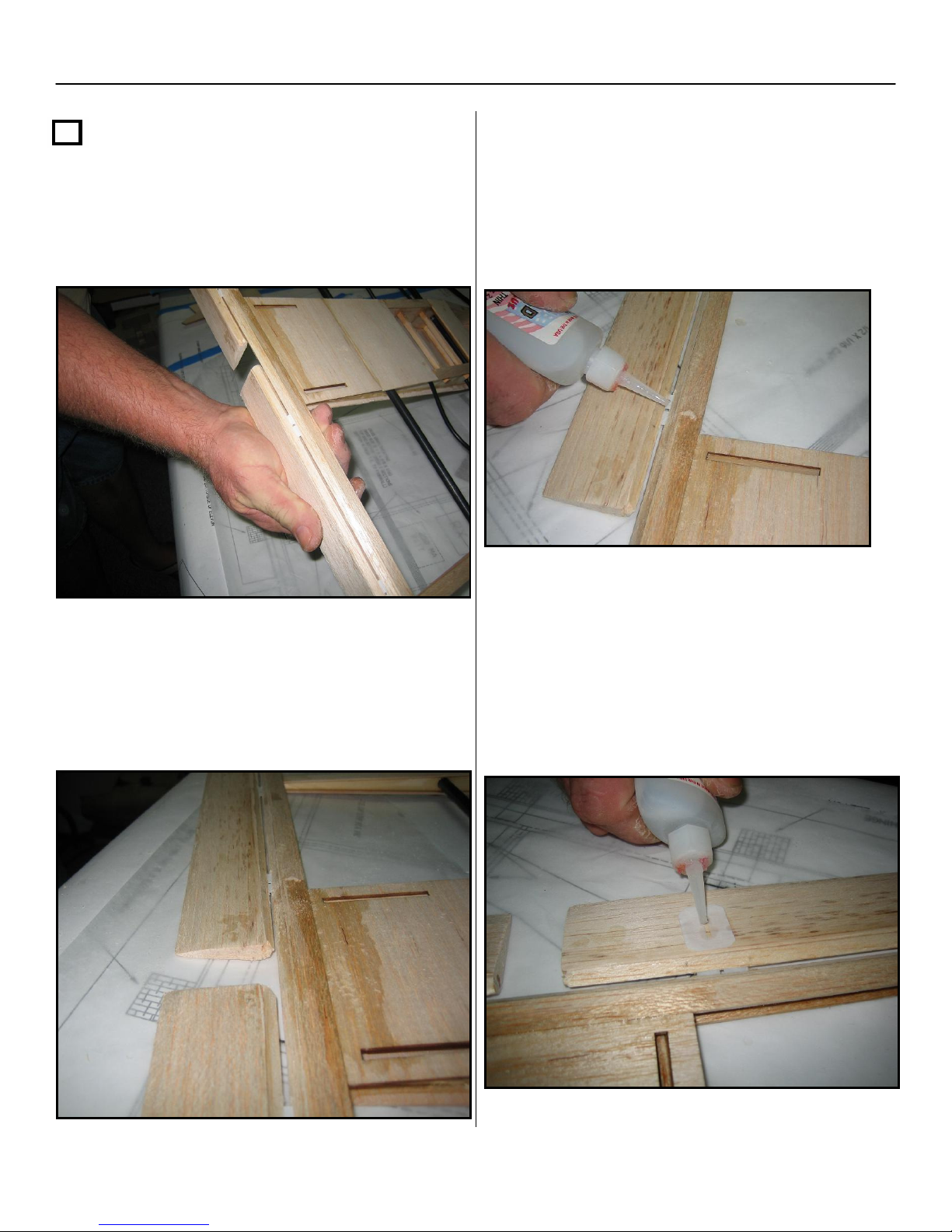
Section 2: Elevon Construction – Cont.
Step 5
Bend each elevon to full deflection (about 90
deg.). Be careful to not bend so far as to pull
the elevons and trailing edge apart.
With the airframe lying on the table, soak
each CA hinge with thin CA. Allow your first
glue application to dry, then apply glue to
both the top and bottom of all the hinges.
Allow the elevons to return to neutral position
Be careful not to loose the full deflection
spacing that you just set. There should be an
even spaced gap all the way down the
elevon and trailing edge (approx. 1/16”).
Next, place a CA hinge on the top of the
elevon as a “re-enforcement pad” for the
control horn, as per the plans. Once in
position, apply thin CA to the entire “pad” and
allow the glue to dry completely before doing
the same to the bottom of the elevons.
35
Page 36
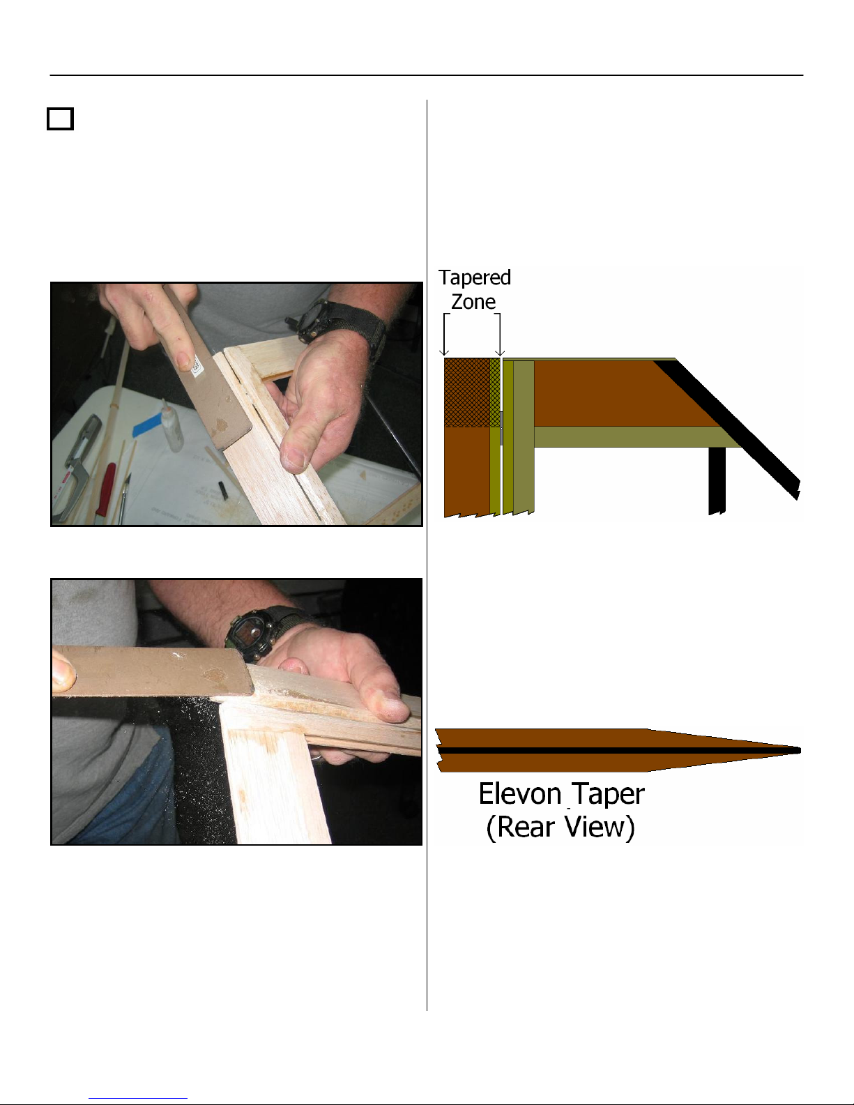
Section 2: Elevon Construction – Cont.
,
Step 5
Next, while using a sanding block or file
taper both outside elevon ends to match the
tapered wing tips.
NOTE: Be sure to match the taper of the
balsa wingtips as closely as possible.
Taper the elevons only in the tapered
zone shown below.
Your tapered elevons should look like this,
when completed.
36
Page 37
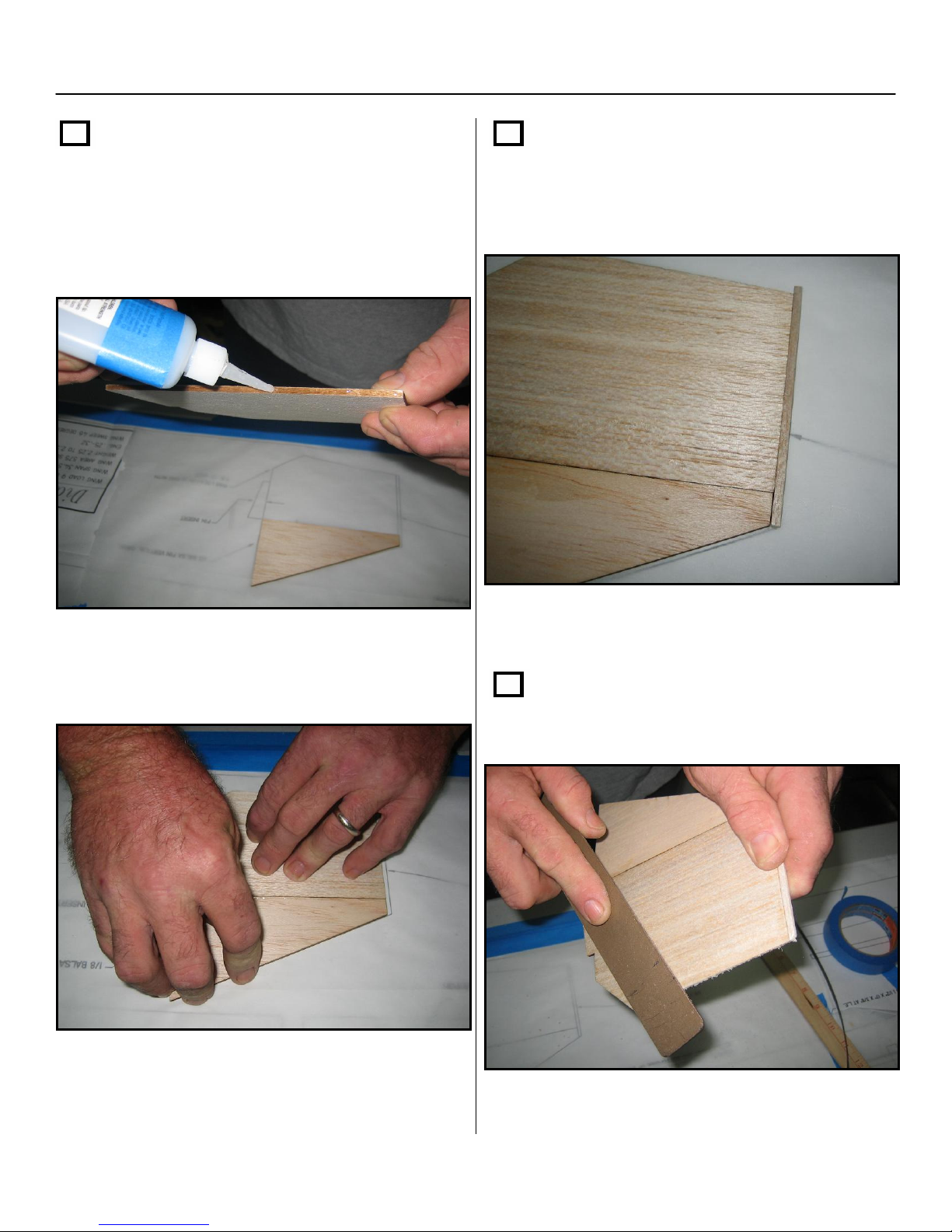
Section 3: Vertical Fin Assembly
Step 1
Cover a clean flat surface with wax paper or
parchment paper and then glue the front and
rear halves of the fin assemblies, as shown
on the blueprint, using thick CA.
Step 2
Next, locate one of the
balsa fin offset fin cap strips. Install them
to the top of the fin as a cross grain cap
strip.
1/8” x 1/8” x 4”
Remember to keep the fins as flat as
possible while the glue dries.
NOTE: Repeat steps 1 and 2 to make two
fins.
Step 3
Sand both leading and trailing edges of the
fins, for less drag.
37
Page 38
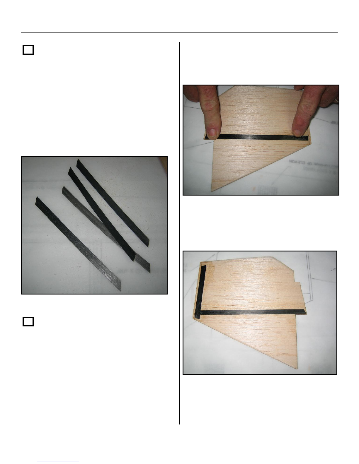
Section 3: Vertical Fin Assembly – Cont.
Step 4
In this step you will be cutting and applying
carbon fiber strips to add strength to the
vertical fins.
Locate the
cut four of each the following pieces;
• ¼” x 6”
• ¼” x 6 ¼”
• ¼” x 4”
1/4”x34” carbon fiber strips and
First, apply the ¼” x 6 ¼” carbon strip along
the seam where the front and rear fin
halves are joined using thick CA
Step 5
Step 5 will show you how to apply the
carbon strips you just precut to the fins. You
will need to repeat this step three more
times so that both sides of both fins have
carbon applied to them.
Next, apply the ¼” x 4” carbon strip across
the top of the fins using thick CA.
38
Page 39
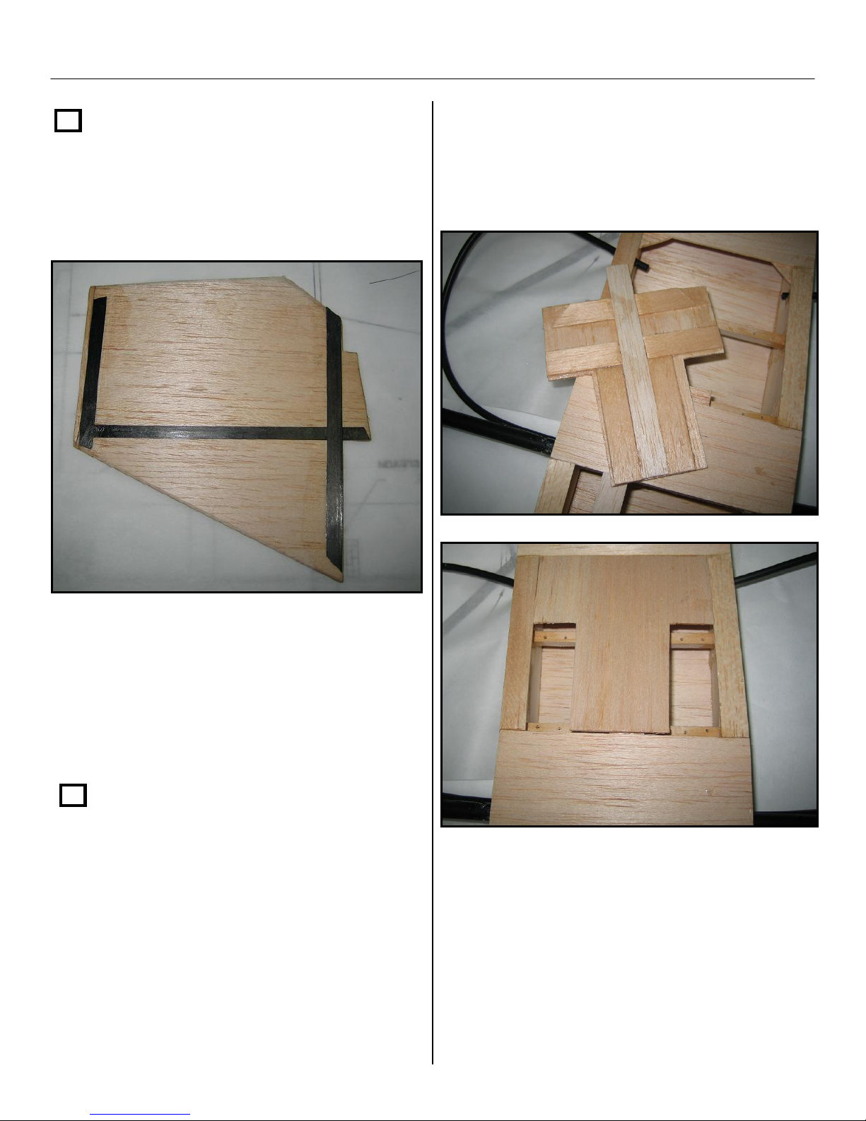
Section 3: Vertical Fin Assembly – Cont.
Step 5 - cont.
Install the ¼” x 6” strip across the bottom of
the fins above the fin insert tab, again using
thick CA.
We have included a few photos of the hatch
we have constructed using left over 1/16”
cap strip and cross grain sheeting.
When you are finish applying all three carbon
strips, trim any excess carbon flush with the
fins. Note: Repeat step 5 for both sides on
both fins.
Step 6 – Optional Servo Hatch
Due to various servo sizes and servo choices
available, we have left it up to the end user to
decide whether or not to fabricate a servo
hatch cover for the servo/ radio
compartment. A servo hatch is not
necessary, you can cover the aircraft and
add a small piece of covering to cover the
servo area, but it does simplify things when
access is needed.
39
Page 40
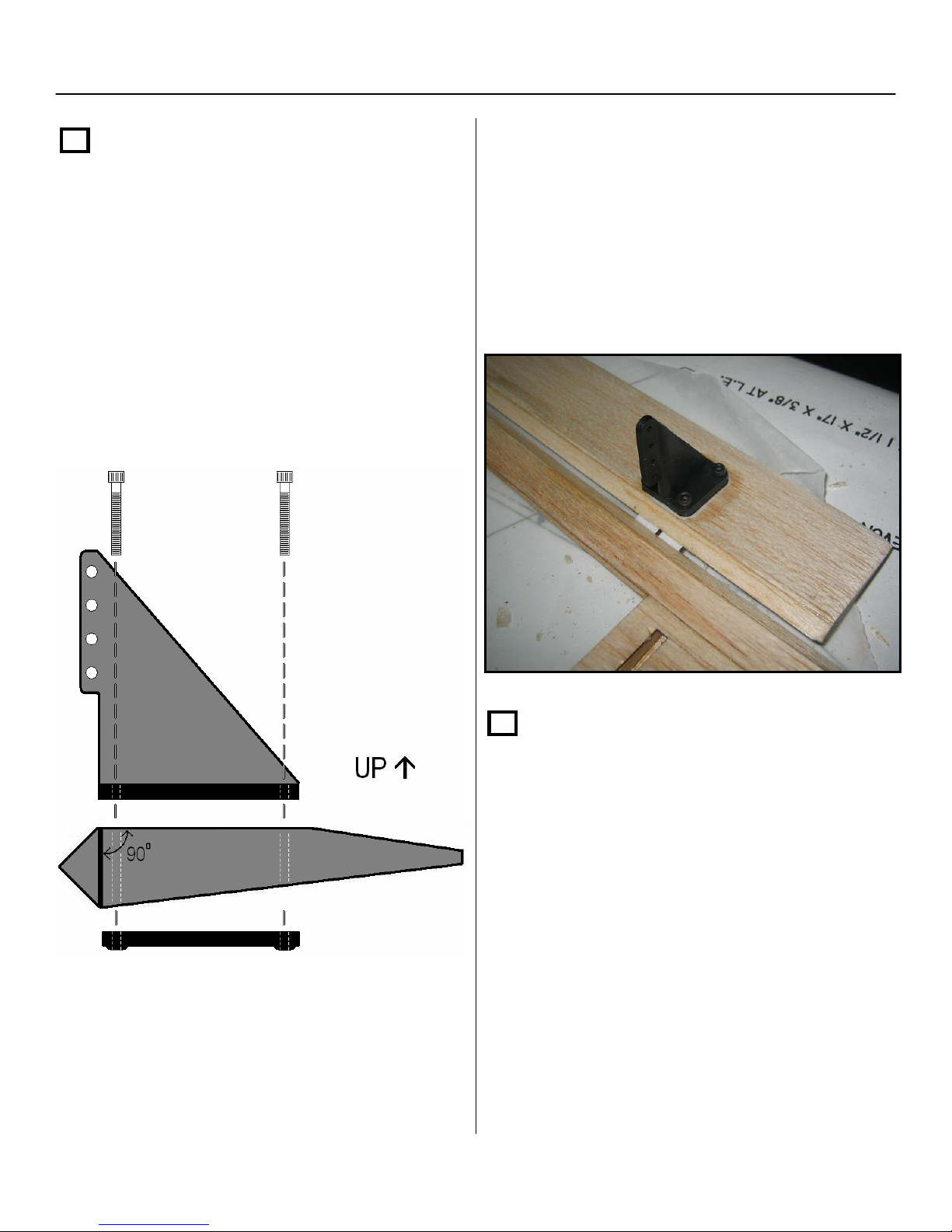
Section 4: Installing the Control Horns and Elevon Linkage
Step 1
Locate the two control horns along with
(8) 4-40 x 1” cap screws from the parts bag.
Before drilling the holes to mount the control
horns, make sure you have properly
positioned the control horn so the base of the
control horn is flush with the seam, where the
triangle stock and elevon stock are joined on
top of the control horn pad.
Once properly aligned, mark and drill four
holes in the elevons using a 1/8” drill bit.
Install the 4-40 x 1” cap screws and
LIGHTLY TIGHTEN AS TO NOT CRUSH
THE ELEVONS!!
Step 2
Next, you will have to determine which hole
on the control horn you will be installing the
ball link. If you are using high torque servos,
we recommend that you use longer servo
arms. No matter what length servo arms you
decide to use with your servos, you should
use a ratio of 1:1.
40
Page 41
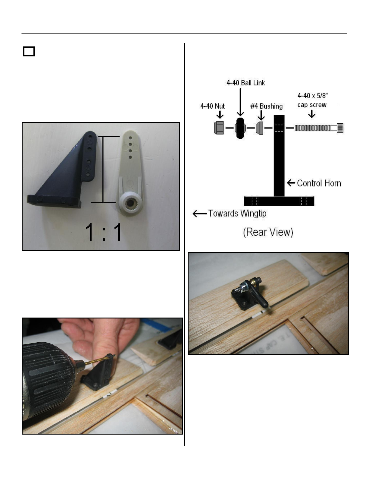
Section 4: Installing the Control Horns and Elevon Linkage – Cont.
Step 2 - cont.
To determine the correct hole to drill, place a
servo arm against the control horn and use
the closest hole to match the length of the
servo arm and control horn with a ratio of 1:1.
Next, install the 4/40 ball links as shown
below on both control horns.
Now that you have determined the proper
hole to drill, drill a 3/32” hole in both of the
control horns. Use a 7/64” bit to drill the holes
in the servo arms.
NOTE: Make sure you don’t over tighten
the ball joint assembly! Check to make
sure the ball joint rotates freely and
effortlessly.
41
Page 42
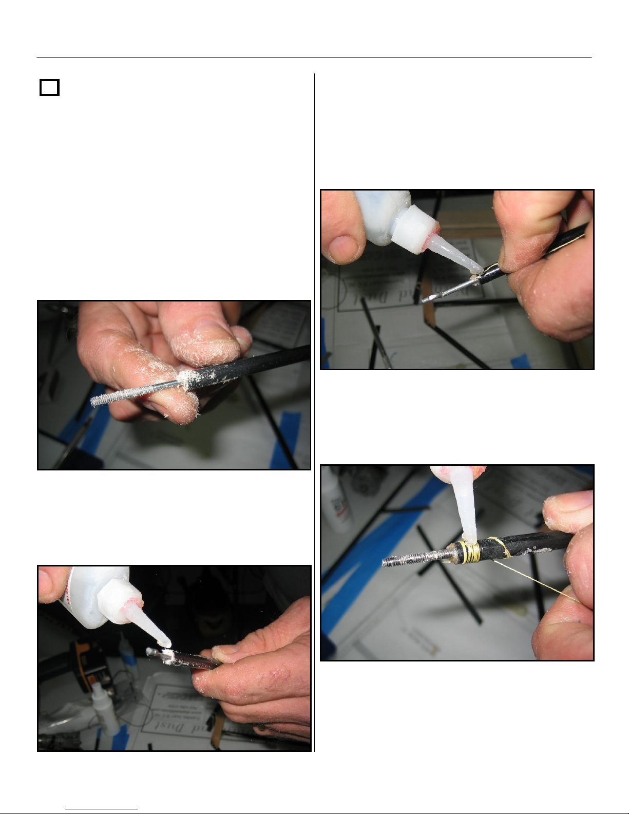
Section 4: Installing the Control Horns and Elevon Linkage – Cont.
Step 3
Locate the two push rods and the two
composite pushrod stiffener tubes. Insert
one of the pushrods into one of the
stiffener tubes, until there is approximately
¼” past the threaded section of the rod left
exposed on one end. Next, take a scrap
piece of balsa sheeting and create some
balsa sawdust with some sand paper or a
file. Take the saw dust and pack the
stiffener tube with enough sawdust to
pack the end.
Next, place a drop of thin CA at the tip of the
stiffener tube and wrap about 6 wraps of
Kevlar thread around the tube.
Once you have the sawdust packed in, wick
in some thin CA and allow it to dry. Do this
for both ends on both pushrods.
When you are done wrapping the Kevlar,
apply thin CA and allow it to dry.
42
Page 43
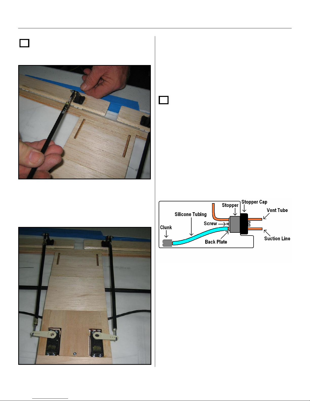
Section 4: Installing the Control Horns and Elevon Linkage – Cont.
Step 4
Screw the pushrods on to the ball links
on each elevon about halfway to start.
Note: You must power on your radio system
in order to properly center your servos at
their true center. Make sure your sub-trims
are zeroed out as well.
Step 5
Fuel Tank Assembly
Assemble the fuel tank stopper and brass
tubing as shown below. Care should be taken
to not kink the vent tube when bending. Also
make sure to leave approximately ¼” of play
between the clunk and the back wall of the
fuel tank.
Reinstall your elevon servos and install the
control arms to the pushrods, making sure to
install the servo arms in the center of your
servos.
43
Page 44
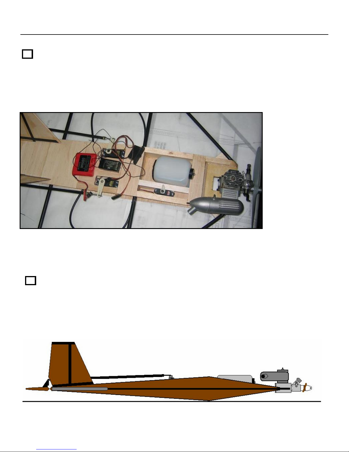
Section 5: Equipment Placement and Pre-Balancing
Step 1
Gather the receiver, receiver battery, power switch harness, fuel tank, throttle servo,
vertical fins and engine with prop. Insert the two vertical fins in the rear slots. Place the fuel
tank in the fuel tank compartment and Install the throttle servo. Center the engine on the
motor mount plate so it can be moved forward or aft later.
Do not drill engine mounting holes at this time!
NOTE: Due to many choices in battery size, type, and weight, It will be up to the end user to
determine the best location and best method in which to place and mount the battery to the
airframe. We have a few suggestions on the plans but they are merely a suggestion.
Step 2
Next, try and arrange your equipment so the aircraft balances perfectly at the high point of
the #1 ribs. The motor mount plate should be level with the table as shown below. NOTE:
once you apply covering the aircraft will be slightly tail heavy in regards to the balance point
you have established with the airframe uncovered. Make sure you allow for movement of
your battery and engine to establish final balancing in Section 7.
44
Page 45
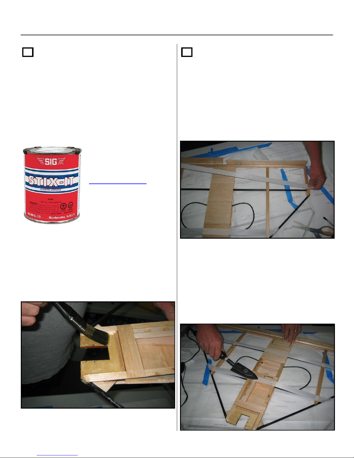
Section 6: Covering the Aircraft.
Step 1
Fuel proofing: Apply a layer of Stix-it on the
wood portion of the airframe where the
covering will contact the wood parts of the
aircraft as well as on the leading edge tubes.
This will make the covering adhere better
and provide fuel proofing to the wood parts of
the aircraft.
Stix-It is available from
SIG Manufacturing at
www.sigmfg.com
Step 2
Now locate the 1” wide roll of Solartex
from the parts bag and with a med to hot
covering iron, apply a strip across the bottom
of the airframe above the forward and rear
spars. Remember to remove the clear
backing from the Solartex before ironing it
down to the airframe.
Apply a moderate coat to the aircraft using a
small brush and allow the Stix-It to dry for
about 5 minutes or so. Make sure you
thoroughly coat the Fuel compartment and
motor mount areas. This will help preserve
your airframe for many years.
Make sure to wrap around the leading edges,
over the forward spar, and around the
wingtips on the strip over the rear spar. Pull
the strips tight to the other side of the
airframe and heat-seal them in place. Next,
apply more Stix-It to the already installed
Solartex and repeat this step for the strips on
the topside of the airframe.
45
Page 46
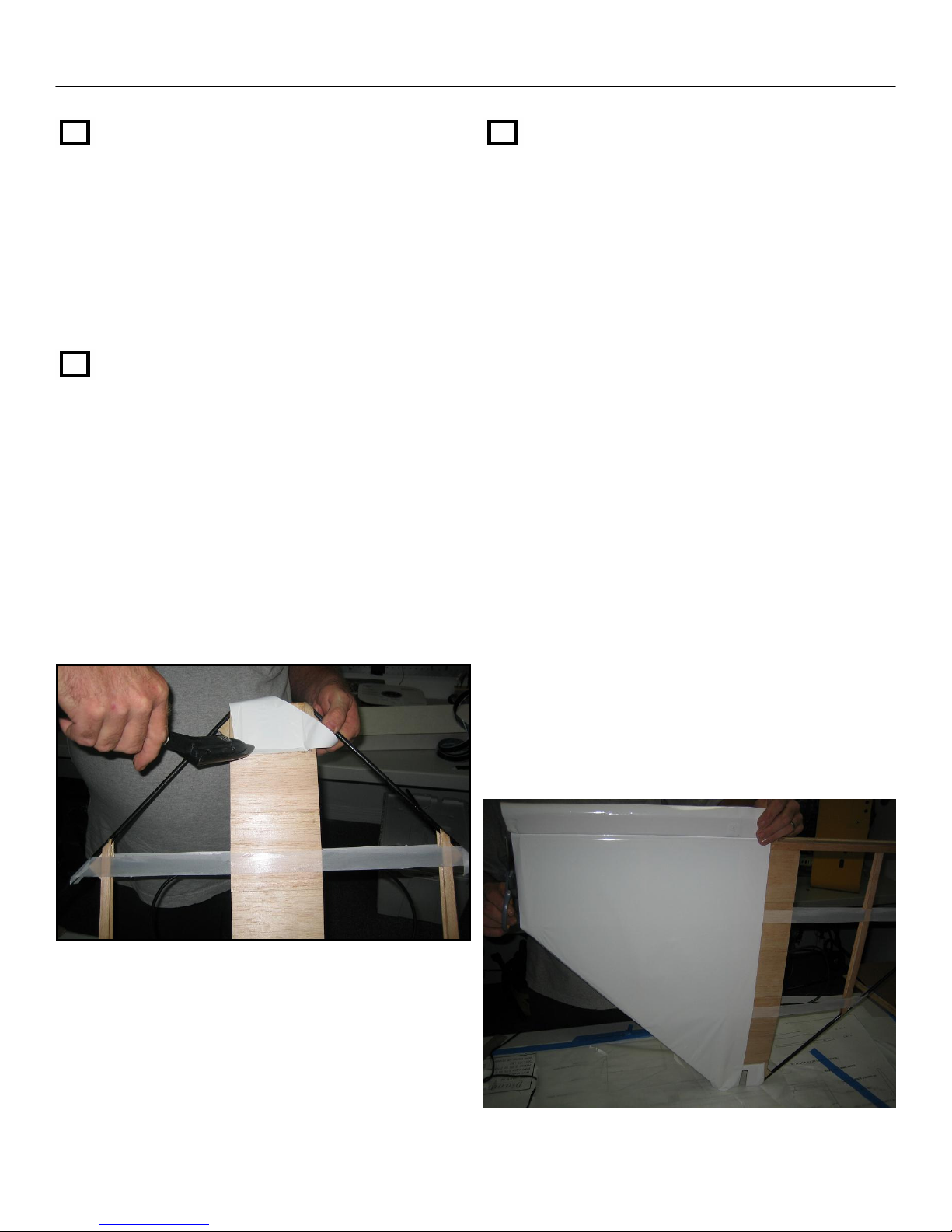
Section 6: Covering the Aircraft - Cont.
Step 2 - Cont.
Apply a final coat of Stix-it to the top of the
Solartex strips. This important step will allow
the covering to have more attachment area
as well as provide better adhesion to the
Solartex strips.
Step 3
The covering procedure is best started by
covering the motor mount first. We
recommend using Hangar 9 Ultracote or
Solartex to cover the Diamond Dust. These
coverings have proven to be more resilient
and will not shatter as easily with age.
Cover both the top and bottom of the motor
mount .
Step 4
Follow the same methods as covering most
aircraft. Start with the bottom and cover half
of the airframe at time, making sure the first
half completely covers the center cross
grain sheeting and the elevon. Using an
iron, tack down the center, then pull it tight
and tack it down at the tip. Do the same
with the leading and trailing edge. When
this is complete, seal the entire perimeter
while pulling all the wrinkles out. DO NOT
TIGHTEN COVERING WITH IRON OR
HEAT GUN AT THIS TIME! Iron the
covering into the crevice between the
elevon and trailing edge and entire elevon,
while holding the elevon at full deflection.
The wing and elevon should be covered
using one continuous piece of covering.
NOTE: Make sure to fully deflect the
elevons when ironing the covering in the
hinge area.
46
Page 47
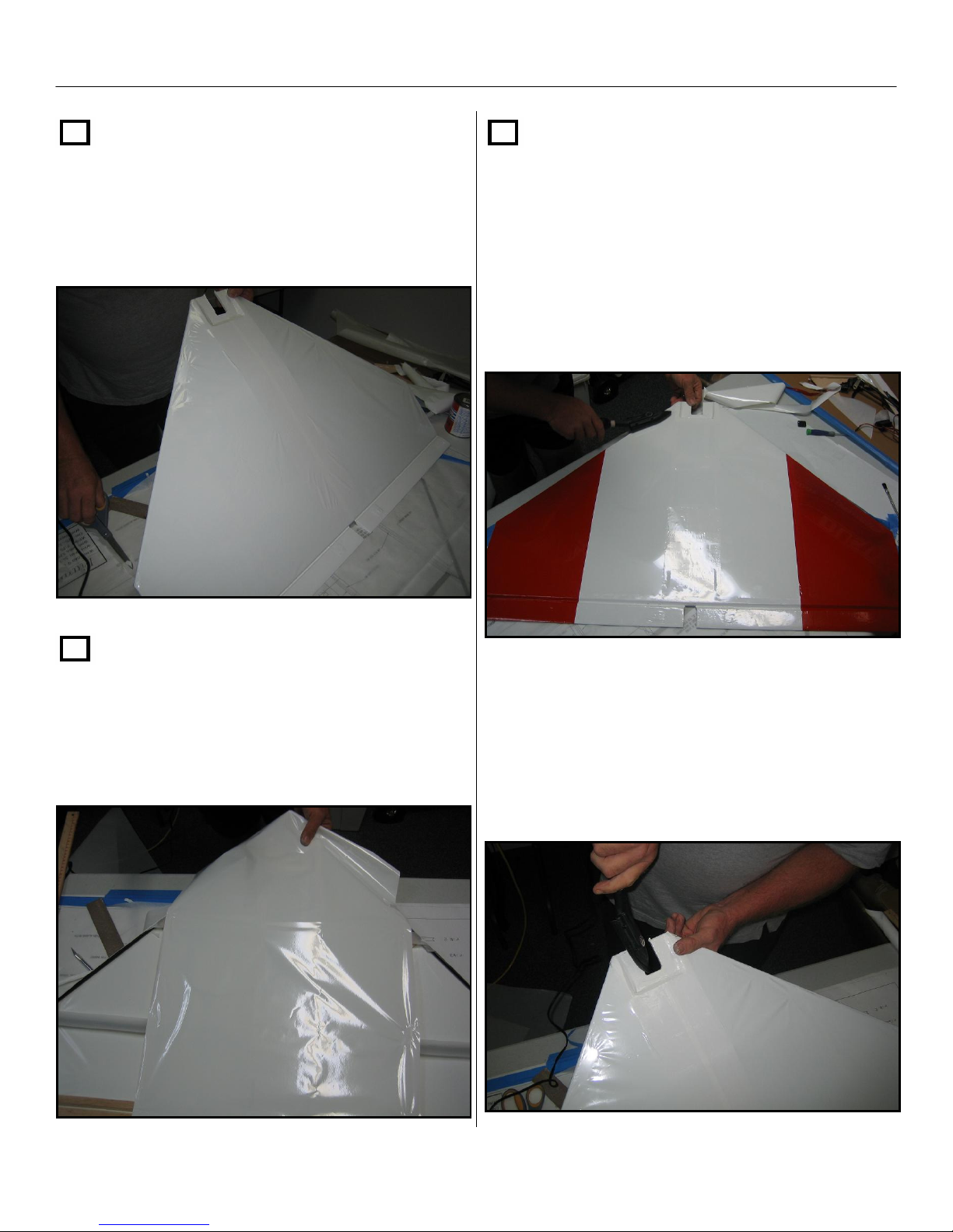
Section 6: Covering the Aircraft - Cont.
Step 5
Cover the other bottom half in the same
manner as shown in step 4. Make sure you
overlap the center section by at least ½”.
Step 7
In this step you may choose to cover the
remaining tip sections of the wings with a
different color. This will help with orientation
when the Diamond Dust is in the air. Make
sure you overlap the first layer of covering
over the #2 ribs.
Step 6
Turn the airframe over and install a piece of
covering that will cover the entire center
section, including the elevons all the way out
to the #2 ribs.
Once you have all of the covering installed,
make sure to tack down the covering and
make a final pass along the leading edges
and over the center sheeting and motor
mount area.
47
Page 48
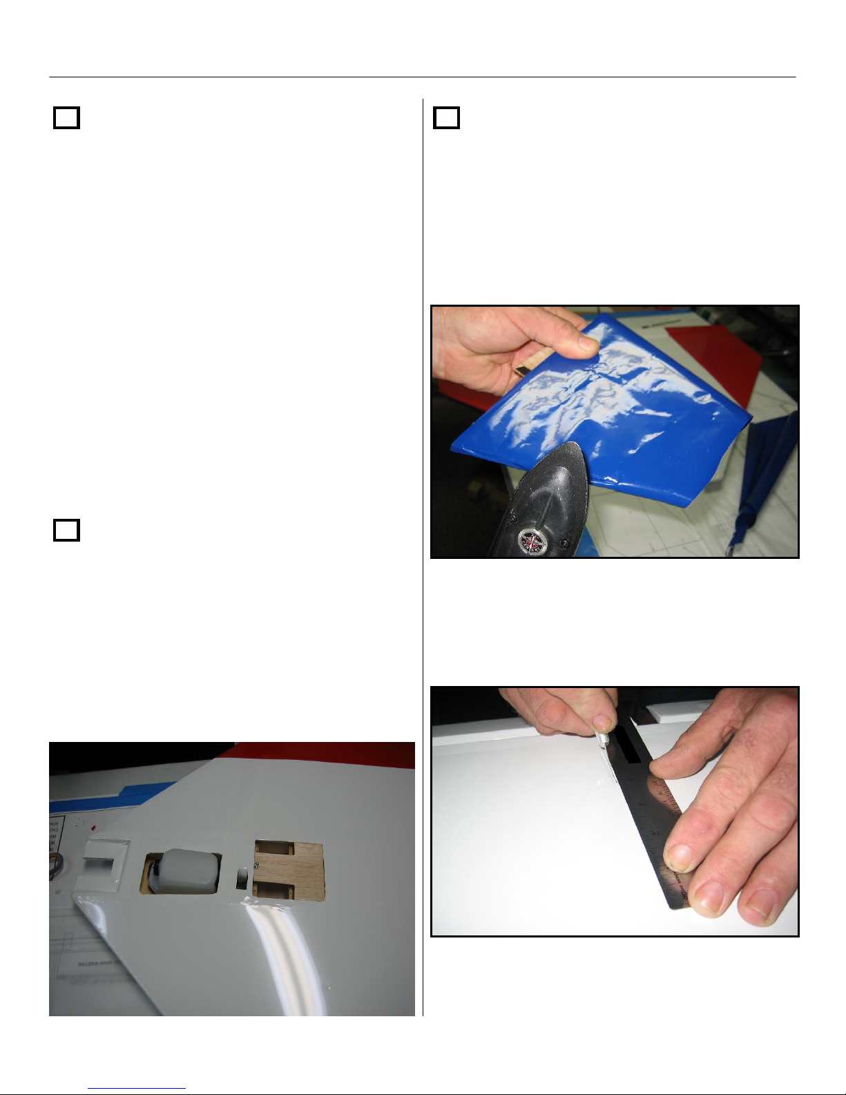
Section 6: Covering the Aircraft - Cont.
Step 8
Look at the aircraft from a frontal view and
determine if both wingtips are even with
each other. If not keep this in mind while
tightening the covering so you can make any
minor corrections. If this aircraft does not
trim out the same at high and low speeds
then you probably have some difference in
wingtip incidence and this can still be
corrected by re-tightening the covering.
Tighten the covering lightly on each side
before tightening completely.
Step 7
Cover both vertical fins with covering. Make
sure to not cover the bottom of the fin or the
fin insert tab. Make sure when you cover the
fins that they are on a flat surface to keep
them straight.
Step 9
Once the covering is tightened, cut the
covering over the radio and fuel tank
compartments. You might want to leave
some extra around the compartments so
you can roll the covering into the openings
with your iron.
Next Carefully cut out the fin insert holes that
are located on the rear top sheeting of the
airframe.
48
Page 49
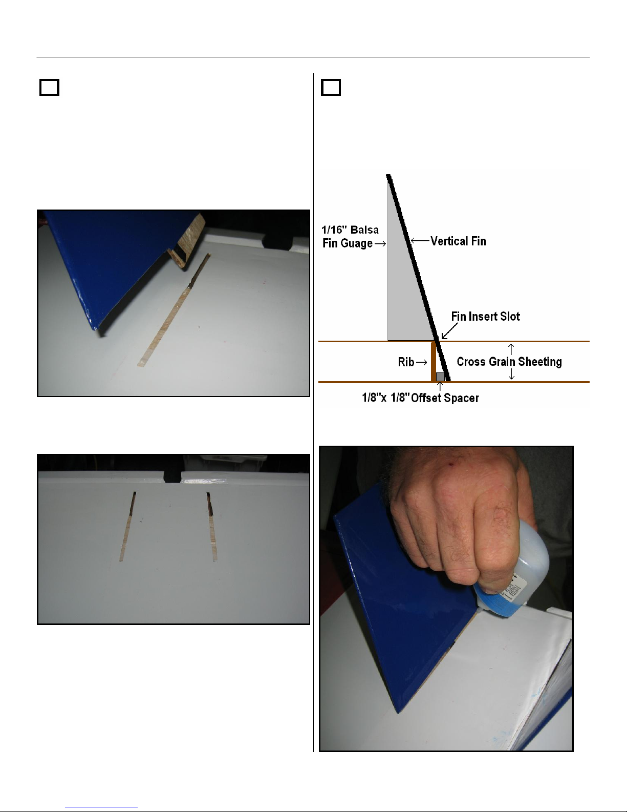
Section 6: Covering the Aircraft - Cont.
Step 8
Insert a vertical fin in the fin insert slot and
mark with a pencil where the fin makes
contact with the cross grain sheeting. Then,
cut away the covering to expose the balsa
sheeting underneath the vertical fin.
Step 7
When installing the fins, use the fin
gage. Use thick CA on the fin insert where it
makes contact with the offset spacer and the
bottom cross grain sheeting.
Repeat this step for both slots.
After installing both fins, lay a small fillet of
thick CA around the base of both fins.
49
Page 50
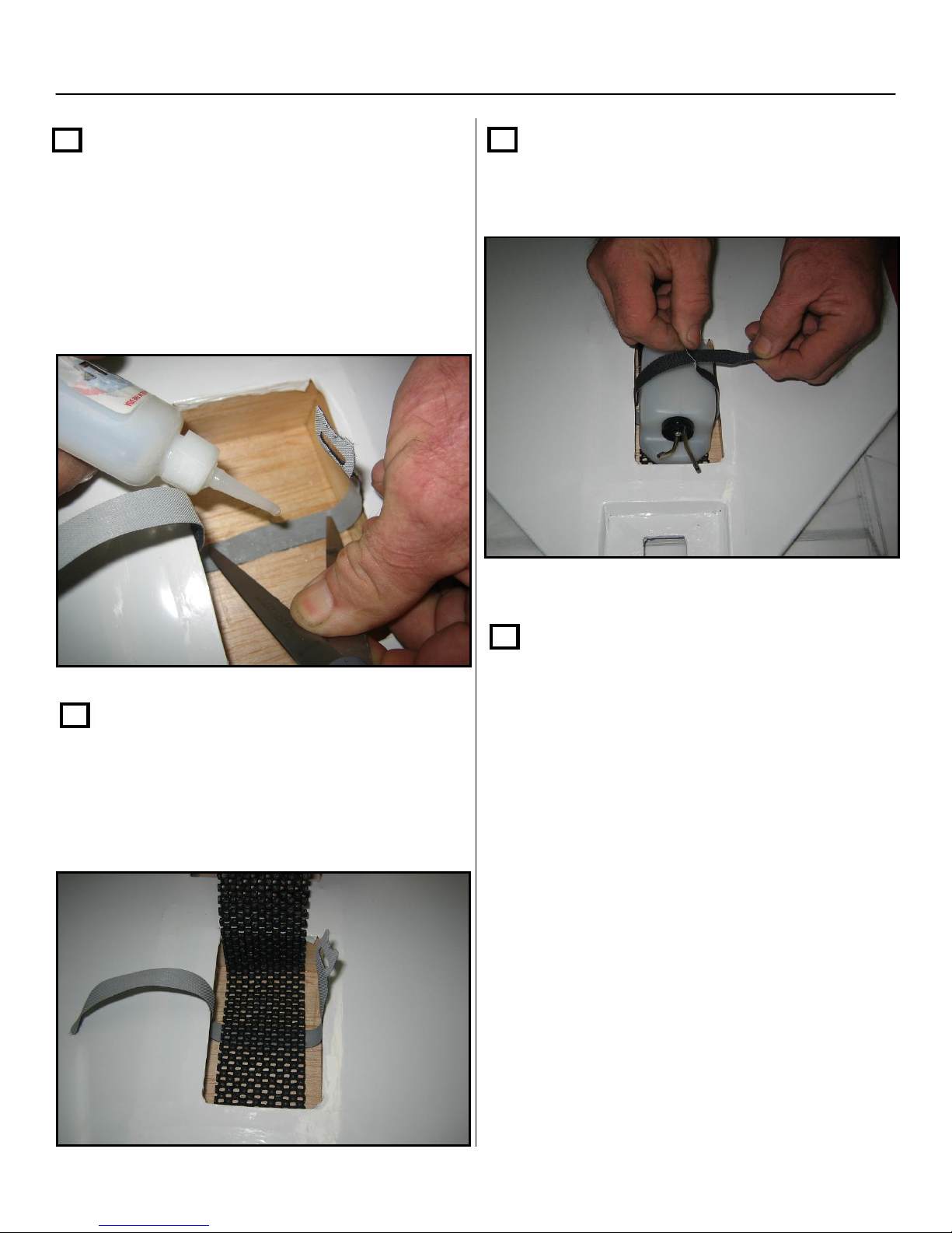
Section 7: Fuel Tank Installation
Step 1
Locate the Velcro strap from the kit and place
it in the middle of the fuel tank compartment
and glue with thin CA. Make sure to glue
the “loop” side down. The eye side of the
strap Should stick out approximately 2 to 3
inches.
Step 3
Install the fuel tank and latch the Velcro strap
around the fuel tank.
Step 2
Next, place a small amount of foam rubber or
padding where the fuel tank will go.
Step 4
Attach your fuel lines from the tank to
carburetor. Make sure you connect the pick
up line
50
Page 51
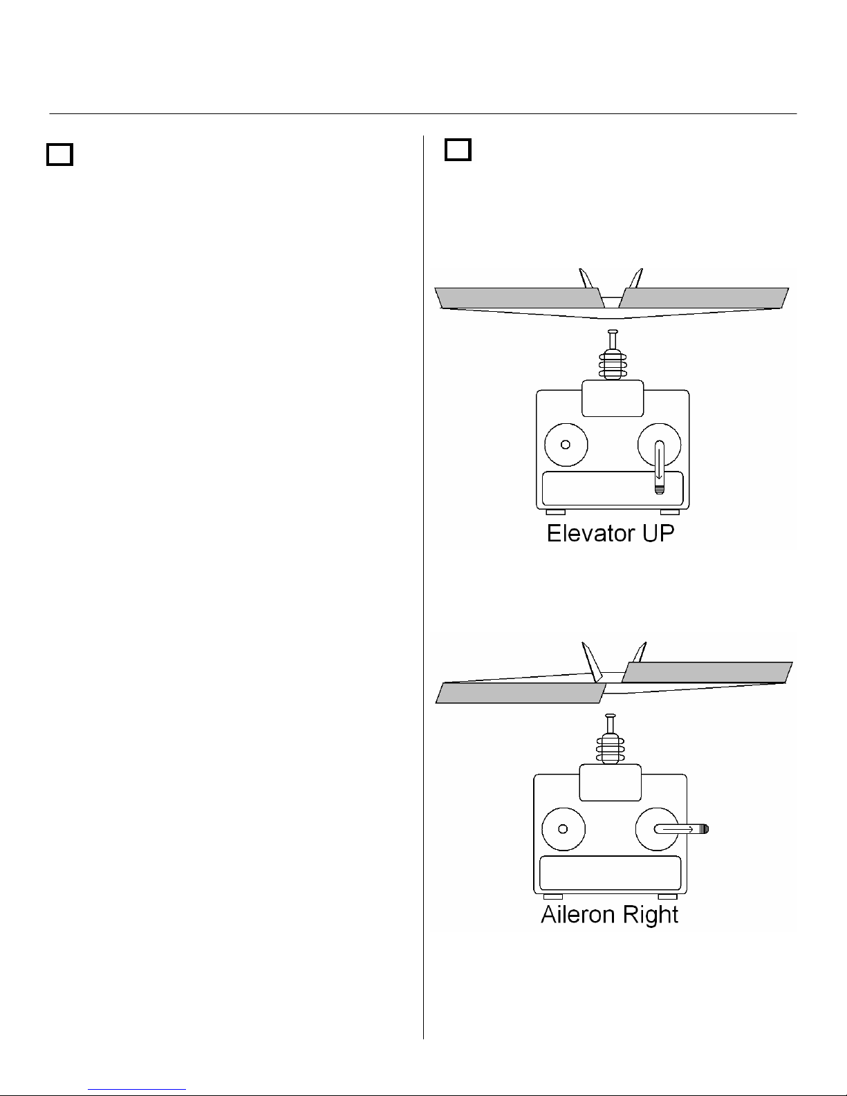
Section 8: Final Equipment Installation
Step 1
Make sure your radio equipment is operating
correctly and your servo arms are centered.
Also be sure to zero out your trims and servo
trims on your transmitter BEFORE installing
your servo arms at center! This also includes
checking servos for proper direction before
attempting to cover the air frame
as
mentioned earlier.
Note: You may need to alter your radios
Step 2
Ensure you have proper servo direction
before you install servos.
mixing in order to achieve proper orientation.
Some radios offer a delta wing configuration
Tip: Because of the amount of force placed
on the Diamond Dust’s control surfaces,
plastic geared servos can fail prematurely.
Therefore we strongly suggest the use of
metal geared servos like the JR DS9411,
DS8611A or Hitec HS-5625MG.
Both servos pull forward
Right Servo pulls forward
Left servo pushes back
51
Page 52
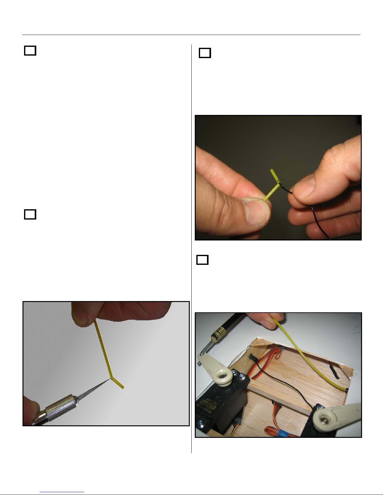
Section 8: Final Equipment Installation – Cont.
Step 3
After you have established proper servo
movement and centering, Install your elevon
servos in the servo/ radio compartment and
attach the control linkage to the elevons.
NOTE: Complete steps 4 through 7 only if
you have a receiver that has a long wire
antenna. If you are using a spread spectrum
receiver, then install your receiver as per the
manufacturers instructions and then please
proceed to Step 8.
Step 4
Step 5
Pull the short semi-cut section back to open
the tube so you can insert the end of the
antenna in the open end on the short side of
the cut.
Locate the small yellow antenna pull tube
and cut a small slit halfway through the tube
about ½” back from one end. Leave enough
tubing attached so you can hinge the ½”
piece of tubing back
Step 6
Insert the opposite end of antenna pull tube
into one side of the antenna tube and feed it
through until it comes out the other side
.
52
Page 53
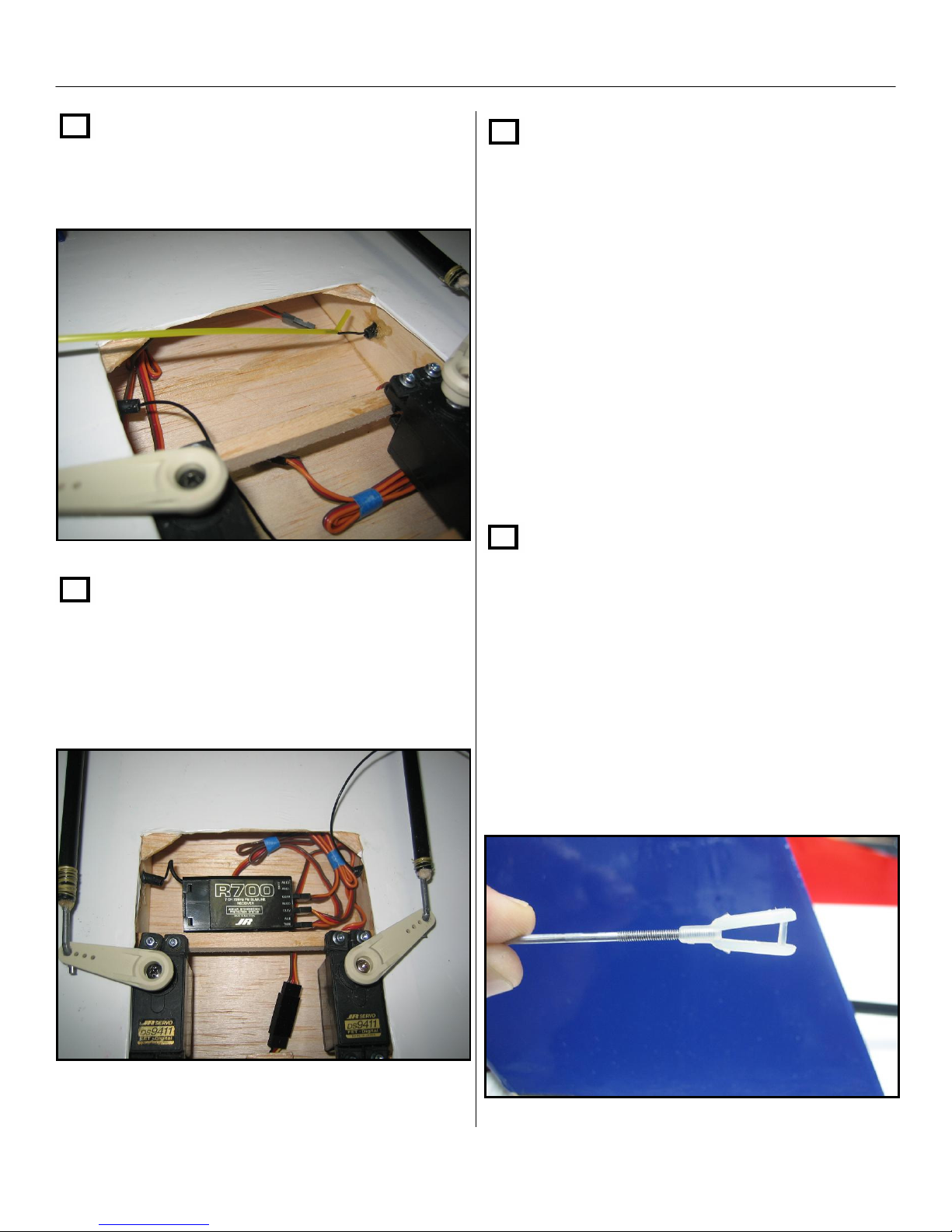
Section 8: Final Equipment Installation – Cont.
Step 7
Continue pulling the pull tube until the
antenna exits the other side of the guide
tubing..
Step 8
Step 9
NOTE: Due to battery size, type, and weight,
It will be up to the end user to determine the
location and manner in which the battery will
be attached to the airframe. We have a few
suggestions on the plans but they are merely
Suggestions.
Install the battery in the location you
determined in Section 5. You may have to
slide the tank forward or backwards in order
to insert you battery at the desired location.
Step 10
Locate the 2-56 pushrod and nylon clevis.
Install your receiver in the location you
established when balancing the aircraft in
Section 5.
Thread the nylon clevis onto the 2-56
pushrod about half way on to the threads.
Attach the clevis to your engine and
determine the correct length needed and
create a z bend at the servo arm.
NOTE: make sure your servo arm is in the
proper throttle position in respect to your
carburetor position.
53
Page 54
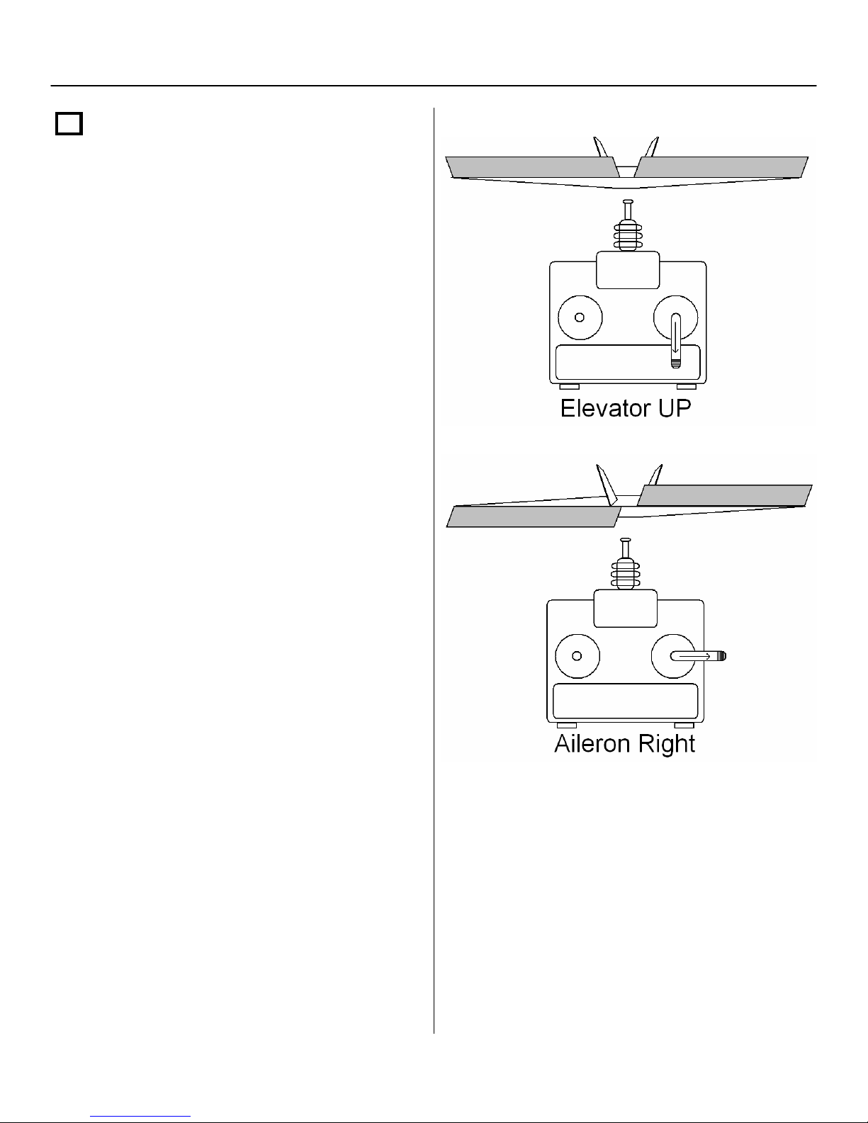
Section 9: Final Inspection/Control Throws
Step 1
Control Throws:
Give the aircraft a complete check over and
make sure the airframe and all control
surfaces are straight.
Also make sure that with up and down
elevator your elevons stay equal through
their range of motion.
Start out with 1” up & 1” down of travel with
both elevator & ailerons. Later, you can
increase the travel on the elevator until it
starts to stall for high rate. You can also
adjust the aileron throws, until they reach full
deflection.
We recommend that you use 100% expo on
your ailerons and 25% on your elevator for
the test flight.
Low Rate High Rate
Elevator 3/8” up ¾” up
Aileron 3/8” up Max Throw up
3/8” down ¾” down
3/8” down Max Throw down
Make sure that you have the proper direction
in relation to your radio stick moves.
54
Page 55
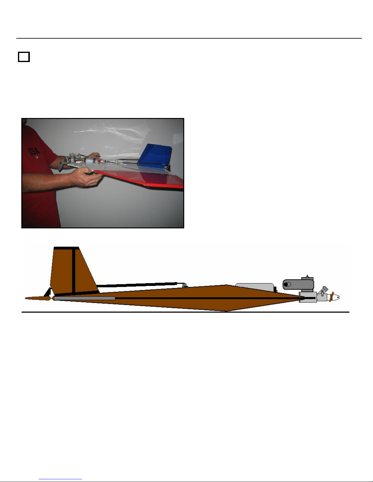
Section 10: Balancing The Diamond Dust
Step 1
Recommended CG:
An important part of preparing the aircraft for flight is properly balancing the model.
The recommended Center of Gravity (CG) for the Diamond Dust is at the high point of the
main ribs to ½” in front of the high point.
To properly check the balance the aircraft,
suspend the plane with your fingers on the
leading edge of the wing where the forward
main spar intersects the leading edge.
If necessary, move the battery pack, receiver, or add weight to either the nose or the tail until
the correct balance is achieved. Stick-on weights are available at your local hobby shop and
work well for this purpose.
Note: It is always better to move equipment around on the aircraft instead of adding weight in
order to achieve proper balance.
If you have assembled this aircraft with the components we have suggested,
your balance should be very close.
Remember you can still move your engine forward or backwards on the motor mount plate.
55
Page 56
Section 11: Pre-Flight & At the Flying Field
Step 1 Preflight check:
Charge both the transmitter and main battery
pack for your airplane. Use the
recommended charger supplied with your
particular radio system, following the
instructions provided with the radio. In most
cases the radio should be charged the night
before going out flying.
Check the radio installation and make sure
all the control surfaces are moving correctly
(i.e. the correct direction and with the
recommended throws).
Check all the control horns, servo arms and
clevises to make sure they are secure and in
good condition. Replace any items that would
be considered questionable. Failure of any of
these components in flight would mean the
loss of your aircraft.
Step 2 Range testing the radio:
Step 3
Initial Instructions for Takeoff
Have an assistant hold the aircraft from
behind with one hand over the leading edge
of each wing tip. When engine is running ½
to ¾ power, have your assistant release the
aircraft in a level or slightly nose high
altitude. If you are using a .25 engine or
larger just release, DO NOT TOSS, the
aircraft. It will have ample power and will
remain in better control if you simply release
it. If using, smaller than a .25 then a gentle
toss may be necessary. Be careful not to
toss towards the ground or too nose high. If
the engine quits upon release it may have a
bad glow plug or it just may be accelerating
faster than the fuel can be supplied. Try a
new plug and or launching at lower throttle
setting.
Before each flying session, range-check your
radio. This is accomplished by turning on
your transmitter with the antenna collapsed.
Turn on the radio in your airplane. With your
airplane on the ground, you should be able to
walk 30 paces or 75ft away from your
airplane and still have complete control of all
functions.
If not, do not attempt to fly! Have your radio
equipment checked out by the manufacturer.
56
Page 57
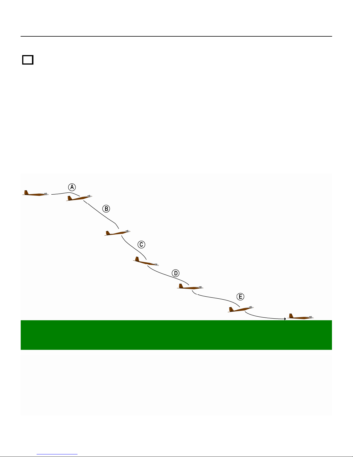
Section 11: Pre-Flight & At the Flying Field – Cont.
Step 4
LANDING:
NOTE: Landings are usually done on soft grass. Dirt or sand is not recommended.
(A) Get into a high approach and shut off engine.
(B) While at high altitude slow the aircraft down by bringing it to nose high attitude and get
the feel of its low speed glide characteristics.. Be careful not to stall the aircraft.
(C) Once you have done this gently push the nose down to build up flying speed and bring it
in for the final approach being careful not to build up too much speed.
(D) Make a final slow down by gently flaring the aircraft.
(E) Hold your flare and the aircraft will settle in very controlled on the belly of aircraft.
57
Page 58

58
Page 59

59
Page 60

www.diamonddustrc.com
© 2007 Tetracam, Inc
21601 Devonshire Street
Suite 310
Chatsworth, California 91311
Tech Support – (352) 871-7301
60
www.tetracam.com
Sales - (818) 718 -2119
 Loading...