

Page 1
Diamond Digital DV191/B
Colour TFT LCD Monitor
19” (48 cm) LCD Panel Size
Page 2

Copyright 2004, Mitsubishi Electric Australia Pty. Ltd. All rights reserved.
No part of this publication may be reproduced, transmitted, transcribed, stored in a retrieval system or
translated into any language or computer language, in any form or by any means, electronic,
mechanical, magnetic, optical, chemical, manual or otherwise, without the prior written permission.
Page 3

i
Table of Contents
1
Important Safety Instructions ..........................................1 1
2
Features.............................................................................2 2
3
3 Unpacking the Monitor.....................................................3
4 Hardware Installation .......................................................5
5
5 Windows driver installation .............................................7
6 Setting the Display Resolution........................................8
Choosing the Best Resolution...........................................8
Supported Graphics Modes and Refresh Rate Selection..9
7
7 Adjusting the Monitor.....................................................12
User Controls..................................................................12
Adjusting the Monitor's Display .......................................13
OSD Function Menu .......................................................13
Function Description .......................................................13
8
8 Frequently Asked Questions .........................................17
9
9 Specifications .................................................................19
10 Service Contacts.............................................................21
Page 4
ii
Disclaimer
Mitsubishi Electric Australia Pty. Ltd. makes no representations or warranties,
either expressed or implied, with respect to the contents hereof and
specifically disclaims any warranties, merchantability or fitness for any
particular purpose. Further, Mitsubishi Electric Australia reserves the right to
revise this publication and to make changes from time to time in the contents
hereof without obligation to notify any person of such revision or changes.
Diamond Digital is a registered trademark of Mitsubishi Electric Australia Pty. Ltd.
Microsoft and Windows are registered trademarks of Microsoft Corporation.
All other trademarks remain the property of their respective owners.
Reference Information
For future reference, write the following information about your monitor in
the space below. The serial number is found on the back of the product or
on the bottom of its stand.
Monitor Information
Product Name: DV191/B
Serial Number:
Date of Purchase:
Dealer Information
Dealer:
Telephone
Number:
Address:
Page 5

1
1
11
Important Safety Instructions
Please read the following safety instructions before installing or cleaning your
Diamond Digital monitor:
1. Unplug the monitor’s power cable from the wall outlet before cleaning. Do
not use liquid or aerosol cleaners. Use a soft cloth to clean the monitor
housing.
2. Slots and openings on the back or top of the cabinet are provided for
ventilation. They must not be blocked or covered. This product should
never be placed near or over a radiator or other heat source, or used in a
built-in installation unless proper ventilation is provided.
3. Never push objects of any kind, or spill liquid of any kind into this product.
4. Do not attempt to service this product yourself as opening or removing
covers may expose you to dangerous voltages or other hazards.
5. Do not apply pressure to the LCD screen. Excess pressure can damage
the LCD panel.
6. If any abnormal operation or accident (such as dropping the unit) occurs,
disconnect the monitor from the wall power outlet and contact qualified
service personnel.
7. Turn the audio volume control of the built-in speakers to minimum (0) and
turn the monitor off before connecting or disconnecting any audio cable.
Page 6

2
2
2
2
Features
Your DV191 Monitor features:
♦ XGA (1280 x 1024 pixel) Resolution LCD Panel
♦ High Brightness Level – 300 cd/m
2
(typical)
♦ High Contrast Ratio – 700:1 (typical)
♦ True Colour Display
With 16.2M (RGB 6bit data) colour, the DV191 monitor offers you better
image quality.
♦ High Quality Ratiometric Expansion
With any resolution within the monitor’s specified range, your Diamond
Digital DV191 monitor can expand the image to full screen.
♦ Plug and Play Compatibility with Microsoft
®
Windows® 95, 98, 2000,
Me and XP
♦ Space Saving - only 210 mm deep
♦ Light Weight - only 5.5 kg
♦ Lower Power Consumption
55W maximum during operation with audio.
♦ Power Saving
Power management complies with VESA DPMS standard. When the
system is idle (in monitor off mode), the monitor automatically cuts its
power consumption to less than 3 W.
♦ On Screen Display
Allows you to adjust all settings simply using on-screen menus.
♦ Built-in Stereo Amplifier and Speakers
♦ Support Kensington security locks
Page 7
3
3
3
3
Unpacking the Monitor
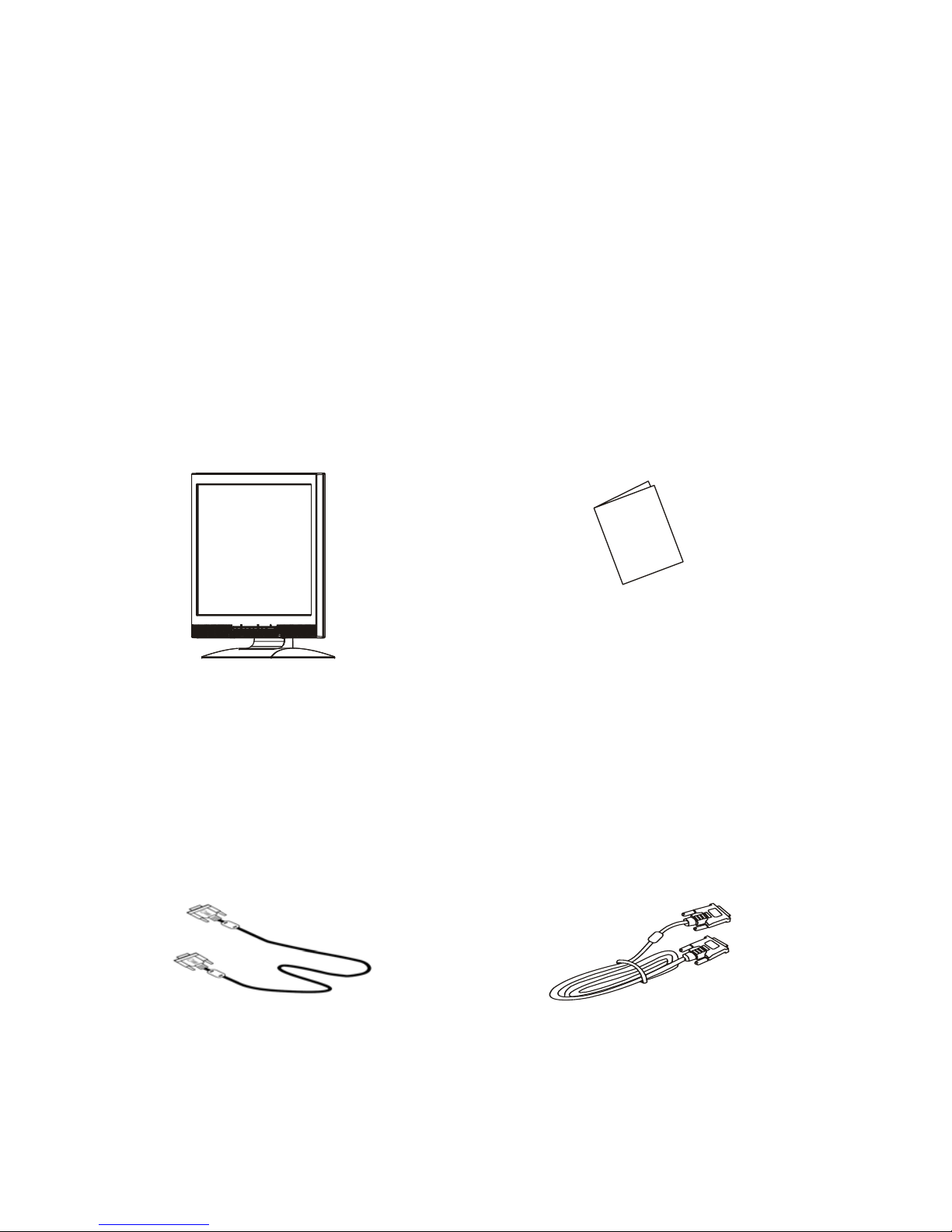
Please check that the following items are included with your monitor. If they are
missing or damaged, please contact your place of purchase
immediately.
LCD monito
r
User’s Manual
U
s
e
r
'
s
M
a
n
u
a
l
DVI-D Cable
V
GA Cable
Page 8
4
4
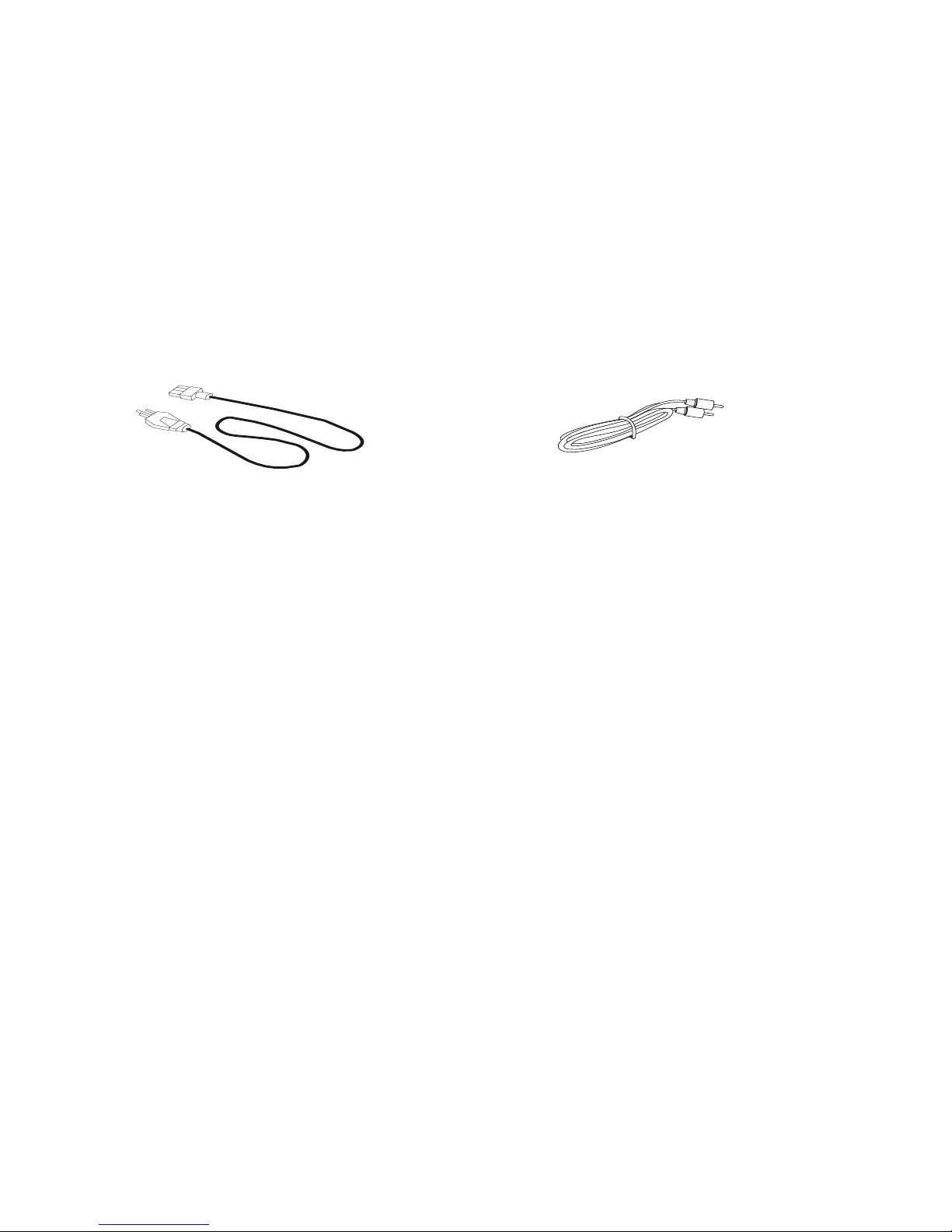
Power Cord Audio Cable
Locate the model name and the serial number label on the back of your monitor,
and write the details of the monitor and your place of purchase in the space on
page (ii) of this manual for future reference.
Page 9
5
5
4
4
Hardware Installation
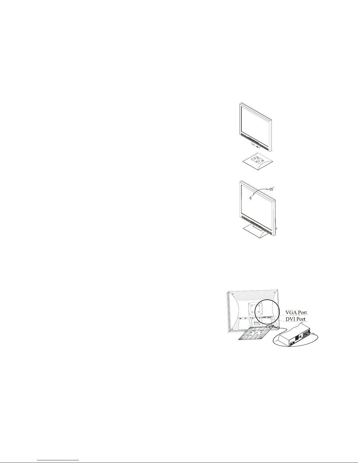
Connecting the Monitor Base
Remove the base from the packing box and place it
on the desk. Next, remove the LCD display and
carefully seat it on the base. (See fig.1-1 )
Figure 1-1
Viewing Angle Adjustment
The LCD Monitor is designed to allow users to
have a comfortable viewing angle. The
viewing angle can be adjusted from -5°to
+25°.(See fig. 1-2)
\ Figure 1-2
Connecting the Display to your Computer
Using the VGA cable
1. Power off your computer.
2. Connect one end of the VGA signal cable to
the LCD Monitor’s VGA port. (See Fig 1-3)
3. Connect the other end of the signal cable to
the VGA port on your PC.
4. Make sure connections are secure.
Using the DVI cable
1. Power off your computer.
2. Connect one end of the DVI signal cable to the
LCD Monitor’s DVI port. (See Fig 1-3)
3. Connect the other end of the signal cable to
the DVI port on your PC.
4. Make sure connections are secure.
Figure 1-3
Page 10
6
6
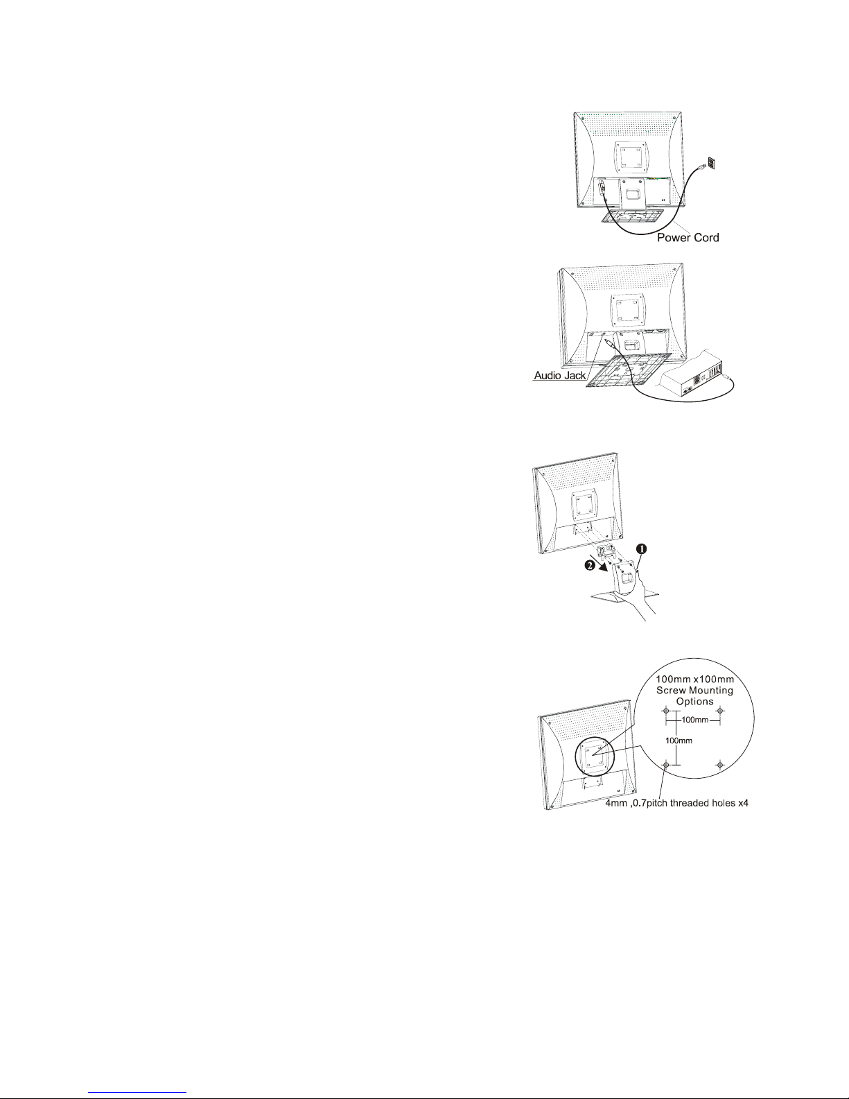
Connecting the AC Power
1. Connect the power cord to the AC socket.
(See Fig. 1-4)
2. Connect the power cord to an AC power
source.
Figure 1-4
Connecting the Audio Cable
1. Connect the audio cable to the Line Out jack
on your PC's sound card. (See Fig. 1-5)
2. Connect the other end of the audio cable to the
LCD Monitor's audio jack.
Figure 1-5
Instructions for VESA Mounting
To detach the LCD Monitor from its stand, unscrew
the two screws n for the monitor stand and pull it
downwards to remove, then unscrew the four
screws o for the monitor stand bracket and pull
this down to remove.
Figure 1-6
Interface for Arm Applications
Before installing the mounting device, please refer
to Fig.1-7.
The rear of this LCD display has four integrated 4
mm, 0.7 pitch threaded nuts, as well as four 5mm
access holes in the plastic covering as illustrated in
Figure 1-2. (These specifications meet the VESA Flat
Panel Monitor Physical Mounting Interface
Standard).
Figure 1-7
Page 11

7
7
5
5
Windows driver Installation
The DV191 is fully Windows Plug and Play compatible so no specific Windows
drivers are required for installation.
Windows 98, ME, and 2000
The first time you start Windows after connecting your new monitor, the system
will detect the monitor and automatically start the Add New Hardware wizard.
Just follow the prompts to load the native Plug and Play drivers.
Windows XP
The first time you start Windows after connecting your new monitor Windows
XP will automatically load the native Plug and Play drivers.
Page 12

8
8
6
6
Setting the Display Resolution
Choosing The Best Resolution
All Liquid Crystal Displays (LCDs) have a fixed resolution that is the same as
the maximum resolution that may be displayed on the LCD. In the case of the
DV191 the LCD resolution is 1280 x 1024 pixels. This is also known as the
“native” resolution of the monitor. Lower resolutions can be displayed at full
screen through an interpolation circuit. Because the lower resolution must be
expanded, the quality of the displayed image is not as good as that available
when the native resolution is displayed. For optimal performance from any LCD
monitor, you must use the monitor’s native resolution.
If you are using Windows 95, 98, 2000, Me, XP or NT 4.0, you can change the
resolution as follows:
1. Double-click the Display icon in the control panel.
2. From the Display Properties dialogue box, select the Settings tab.
There is a slider on the right-hand side in the middle of the dialogue box
that alters the displayed resolution. Set the resolution to 1280 x 1024.
3. For Windows NT users only: select a refresh rate of 60Hz and click Test.
A test pattern will be displayed. Make sure that there are no error
messages shown by the monitor. If an error message is displayed, check
the resolution and refresh rate settings or choose a different refresh rate.
4. Click OK to close Display Properties.
Page 13

9
9
If you are using an Apple Macintosh, change the resolution by doing the
following:
MacOS 8.x/9.x
1. Click the Apple icon at the top, left corner of the screen, select Control
Panel and then select Monitors.
2. Select a resolution of 1280 x 1024 pixels with between 60Hz and 75Hz
refresh rate.
3. If refresh rates of 60Hz or 75Hz are not available, click Recommended in
the Show drop-down box and change it to All. Select the resolution and
refresh rate as above.
A colour depth of either Thousands or Millions is recommended.
MacOS X
1. Click the Apple icon at the top, left corner of the screen, select System
Preferences and then select Displays.
2. Select a resolution of 1280 x 1024 pixels with between 60Hz and 75Hz
refresh rate.
3. A colour depth of either Thousands or Millions is recommended.
Supported Graphics Modes and Refresh Rate Selection
There is no need to choose the highest possible refresh rate when using an
LCD monitor. It is not technically possible for an LCD monitor to flicker. Even at
a refresh rate of 60 Hz you will get an absolutely flicker-free image.
For best results, it is important that you set the graphics adaptor to use one of
the monitor’s preset display modes shown in Tab l e 1 on the next page. Other
graphics signals may be displayed poorly or not at all. Note that the DV191’s
preset modes correspond to VESA or Apple Macintosh standard graphics
signals for these resolutions. All recent models of graphics adaptor should be
Page 14

10
10
able to support these modes. For the native resolution of 1280 x 1024 pixels,
for example, refresh rates of 60, 70 and 75 Hertz are supported.
With Windows 95, 98, ME, 2000 or XP you can change the refresh rate of the
graphics signal as follows:
1. Double click the Display icon in the control panel.
2. From the Display Properties dialogue box, select the Settings tab and
click the Advanced Properties button.
3. For Windows 95, 98, and ME select the Adapter tab, for 2000 and XP
select the Monitor tab. The refresh rate selection field is located in the
centre, at the bottom of the dialogue box.
4. Choose a refresh rate that corresponds with one of the factory modes from
the table below.
5. Click Apply, and then OK twice.
Please Note:
• Graphics modes that are not listed in the table may not be supported. For
an optimal picture it is recommended that you choose a graphics mode
with a resolution of 1280 x 1024 pixels that is listed in Table 1 on the next
page. Resolutions of 640 x 480, 800 x 600 and 1024 x 768 pixels are
supported. The default setting may require some adjustment before use.
• The displayed image may show some distortion or noise that can be
caused by the signal from the VGA card if it does not correspond with the
usual standard. This is not however, a problem with the monitor. If it is still
visible after using the Automatic adjustment, you can usually improve the
displayed image by manually adjusting the phase, horizontal position and
pixel frequency settings using the "Geometry" menu. See Chapter 7,
Adjusting the Monitor, for more details.
• When you shut Windows down you may see interference lines on your
screen. This caused by the manner in which Windows controls the
graphics card at this point and is normal with all LCD monitors.
• To extend the service life of the product, we recommend that you use your
computer's power management functions to turn the monitor off after
extended idle periods.
Page 15
11
11
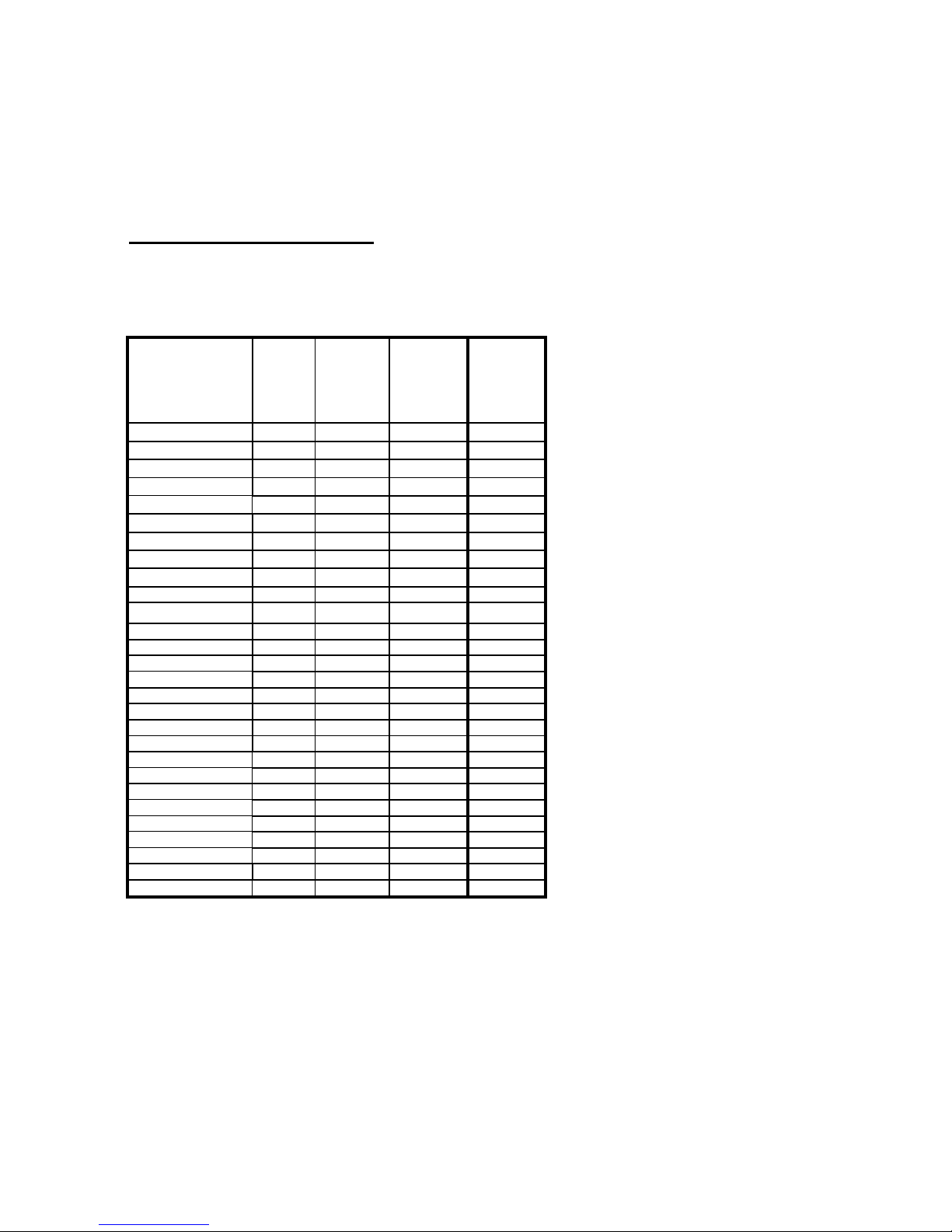
Table 1
Standard Timing Table
If the selected timing is NOT included in table below, this LCD monitor will use the
most suitable available timing.
Resolution Horzontal
Frequenc
y
(kHz)
Vertical
Frequency
(Hz)
Dot Clock
Frequency
(MHz)
Remark
640x350 31.469 70.087 25.175 DOS
640x400 24.83 56.42 21.05
640x400 31.469 70.087 25.175
640x400 31.5 70.15 25.197
640X480 31.469 50.030 25.175 VESA
640x480 31.469 59.94 25.175 DOS
640x480 35.00 66.67 30.24 MAC
640x480 37.861 72.809 31.5 VESA
640x480 37.5 75 31.5 VESA
720x400 31.469 70.087 28.322 DOS
832x624 49.725 74.55 57.2832 MAC
800x600 35.156 56.25 36 VESA
800x600 37.879 60.317 40 VESA
800x600 48.077 72.188 50 VESA
800x600 46.875 75 49.5 VESA
1024x768 48.363 60.004 65 VESA
1024x768 53.964 66.132 71.664
1024x768 56.476 70.069 75 VESA
1024x768 60.023 75.029 78.75 VESA
1024x768 60.24 75.02 80 MAC
1152x864 54.054 59.270 80
1152x864 63.851 70.012 94.499
1152x864 67.50 75.00 108.00
1280x960 60.00 60.00 108.00
1280x960 70.00 70.00 126.00
1280x960 75.00 75.00 135.00
1280x1024 64 60 108 VESA
1280x1024 80 75 135 VESA
Note: Mode 640x350, 640x400 and 720x400 will locate on middle position b ut cann ot
be expanded to full
Page 16
12
12
7
7
Adjusting the Monitor
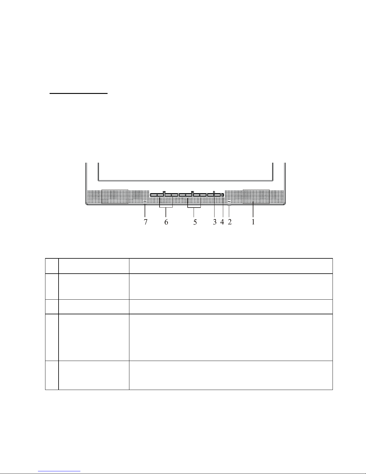
User Controls
A brief description and the location of all LCD Monitor function controls and
indicators:
Figure 2-1
1 Stereo Speakers
PC Audio Stereo output.
2
Speaker Volume
Control
Use to adjust the speaker volume (clockwise to
increase, anti-clockwise to decrease).
3 Power Switch
Turns the display on and off.
4
Power-On
Indicator
LED lights Green colour --- Power is ON.
LED lights Yellow --- Monitor is in "Power Saving Mode".
LED is off --- Power is OFF.
5
Function Select
Buttons
Press either left or right control button for OSD (On
Screen Display) menu selection.
Page 17
13
13
6
Adjustment
Control Buttons
Press the left button to decrease the OSD setting and
press the right button to increase the OSD setting, when
OSD menu is displaying.
7
External
Headphone
Jack
The monitor speakers will be disabled when using an
external headphone or external speakers.
Adjusting the Monitor's Display
OSD Function Menu
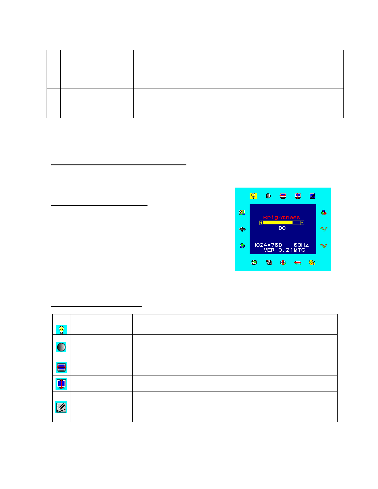
To access the OSD Main menu, simply press one of
the Function Select control buttons, and the menu
diagram will pop up on the screen as shown on Fig.
2-2:
Continue pressing the Function Select buttons to
scroll through the available menu items, then press
the Adjustment Control buttons to adjust the setting
of a selected item.
Figure 2-2
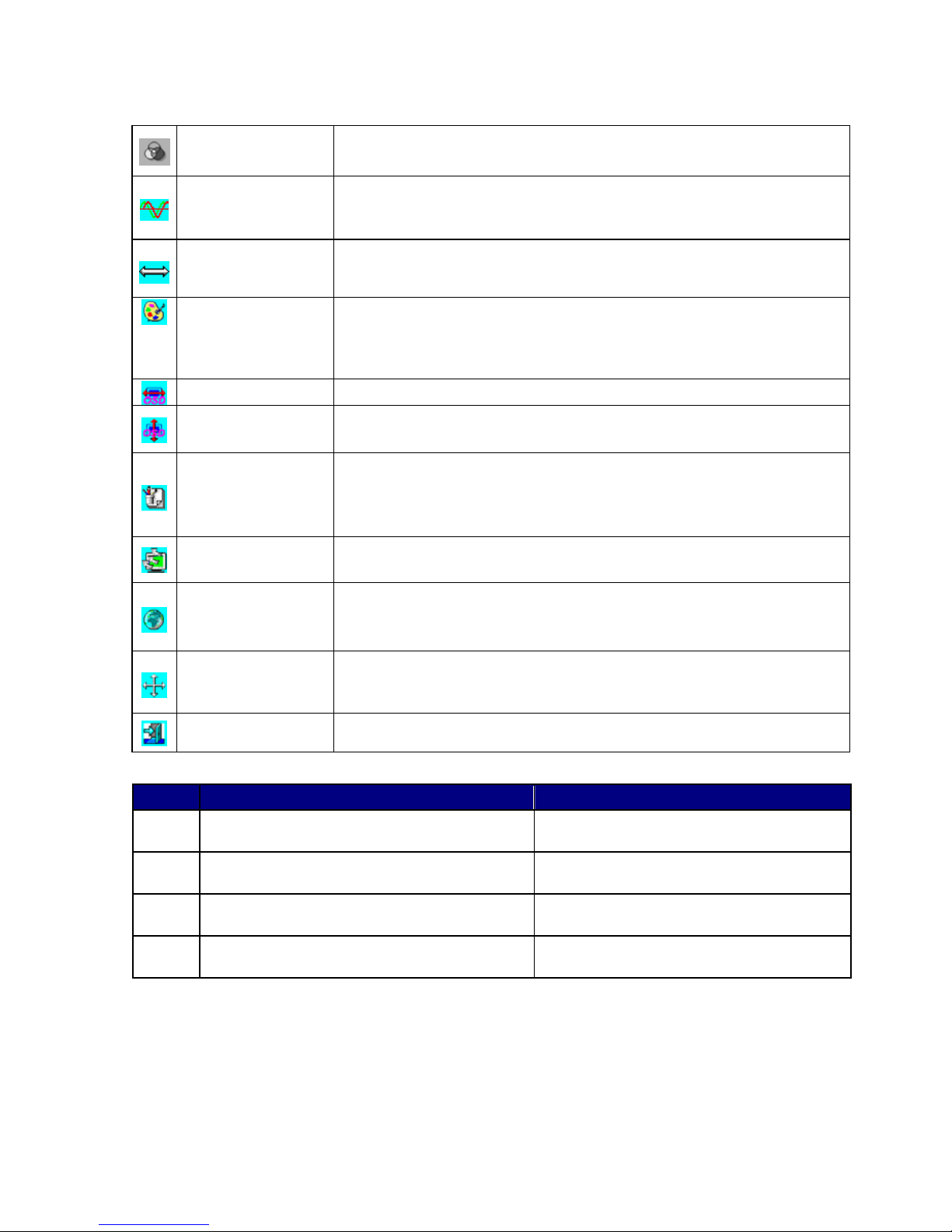
Function Description
Icon Function Function Description
Brightness
This function lets you increase and decrease the screen
Contrast
This function lets you increase and decrease the contrast level of
the screen.
H. Position
This function let's you adjust the display's horizontal position. (Not
available when using DVI).
V. Position
This function let's you adjust the display's vertical position. (Not
available when using DVI).
Sharpness
This function let's you adjust the images sharpness. Five
selections are available. A smoother setting is more suitable for
pictures, while a sharper setting is more suitable for text. (Not
available when using DVI).
Page 18
14
14
OSD
Transparency
This function let's you set the transparency of the OSD menu (Not
available when using DVI).
Phase
This lets you adjust the phase of the pixel clock to eliminate
sampling noise (Not available when using DVI).
Clock
Adjusts the sampling frequency for the Analogue (VGA) to Digital
signal conversion (Not available when using DVI).
Colour
Temperature
This function lets you select a colour temperature. Using the
Adjustment Control buttons to select the required colour
temperature. Please see the diagram below for function and
description. (Not available when using DVI).
OSD H. Position
This function moves the OSD menu window horizontally.
OSD V. Position
This function moves the OSD menu window vertically.
Graph / Text
Because the H and V-Frequencies of both 640 x 400 70Hz, and
720 x 400 70Hz, are the same, this function let's you manually
select either 640 x 400 (graphics mode), or 720 x 400 (text mode)
when running in DOS. (Not available when using DVI).
Recall
The recall function will return all adjusted parameters to factory
preset values.
Language
Nine OSD language options are available: English, German,
French, Spanish, and Italian. Press the left or right adjustment
control button to select other language.
Auto and Input
Select
This function lets you use the Automatic adjustment function to
adjust the Geometry based on the displayed image, or select
either the Analogue or Digital inputs
Exit
Exits the OSD menu.
TABLE 1
Icon Function Description
9300
CIE coordinated Colour Temperature of
9300°K
Sets the CIE coordinate colour
temperature to 9300°K
7500
CIE coordinated Colour Temperature of
7500°K
Sets the CIE coordinate colour
temperature to 7500°K
6500
CIE coordinated Colour Temperature of
6500°K
Sets the CIE coordinate colour
temperature to 6500°K
User
Three colours (Red, Green, Blue) can be
adjusted from the OSD menu
Allows a user to define the CIE
Temperature settings.
Page 19

15
15
Picture Optimisation
The easiest way to obtain an optimal picture is by using the Auto function in the
OSD menu. This only works reliably if the graphics adaptor is set to use one of
the monitor’s factory modes (see Table 1 in the previous chapter) and if you
are displaying a suitable stationary image (such as the Windows desktop).
The monitor will remember the settings obtained by the auto calibration
settings and use them whenever you turn the monitor on. Note that you may
need to readjust the monitor if it is connected to a different computer or if the
computer’s graphics adaptor is replaced.
If you are still not satisfied with the result, you can enhance the image by using
the monitor’s manual adjustment functions.
Manual Picture Adjustment
Adjustments to the displayed image and audio volume are made using the
On-Screen Display (OSD), and the buttons on the front of the monitor.
To manually adjust the image:
1. Display your operating system desktop
2. Open the OSD menu by pressing one of the Function keys on the monitor.
3. Press Fn► or ◄ to select the Clock function.
4. Press ► or ◄ to increase or decrease the sampling clock to get the
optimum picture. Look closely at the picture displayed, especially
surrounding text and icons, for any movement or change. Adjust the Clock
setting and see how this affects this “noise” or movement. Make sure that
in correcting noise in one part of the screen the setting does not create it in
another. You should, with careful adjustment, be able to obtain a picture
with no visible noise in any section of the screen.
5. If some noise or distortion is still visible select Phase using the Fn► or ◄
buttons.
Page 20

16
16
6. With the Clock set to the optimal value adjust the Phase to further optimise
the displayed image. You should now be able, with a combination of the
Phase and Clock settings, to obtain a perfectly stable image.
7. Finalise the manual adjustment using the H. Position and V. Position
functions
If you are still not satisfied with the result, try repeating the above procedure
using a graphics signal that has a different refresh rate.
Please Note:
You must use one of the factory modes when manually adjusting the picture. If
you are having difficulties generating a supported mode, ask your computer
dealer or the distributor or manufacturer of your graphics card for assistance.
The procedures described in this chapter should be performed for every
resolution and type of graphics signal that you wish to use. For example, if a
particular application requires a resolution of 800 x 600 pixels, but all other
applications use the monitor’s native resolution, you will need to display the
test pattern and make adjustments twice.
The monitor will remember your settings and use them whenever you turn the
monitor on. Note that you may need to re-adjust the monitor if it is connected to
a different computer or if the computer’s graphics adaptor is replaced.
Page 21

17
17
8
8
Frequently Asked Questions
The image is blurred, how can I get the best quality picture?
♦ Read chapter 6, Setting the Display Resolution, and select a graphics
signal with the correct resolution and refresh rate. Then read chapter 7,
Adjusting the Monitor, and make adjustments to the displayed image
based on these instructions.
♦ Have you used a VGA extension cable?
If so, remove the extension cable and check the displayed image. Has the
image quality improved? Optimise the image using the procedures in
chapter 7 with the extension cable removed. Reconnect the extension
cable once the image has been optimised. Depending on the
characteristics and type of the extension cable, some blurring or distortion
may occur due to conduction losses of the extension cable. You can
minimise these losses by using an extension cable with better conduction
quality or with a built-in booster.
♦ Does the blurring only occur at resolutions lower than the native
(maximum) resolution?
Please read chapter 6, Setting the Display Resolution. Select a graphics
signal that uses the monitor’s the native resolution (1280 x 1024 pixels).
Why does the image look yellow, blue or pink instead of showing the
correct colours?
♦ The most common cause of this problem is a loose VGA signal cable or
connector. Check that the cable is securely connected to the computer.
♦ Check the VGA signal cable for damage. If any pins are bent or broken off,
contact your dealer or an authorised Mitsubishi Electric service agent (see
Chapter 10 for details).
Page 22

18
18
No image is displayed, what can I do?
♦ Check that the light (LED) next to the monitor’s power button is lit and is
green in colour. If the LED is green, press one of the Function Select
buttons on the monitor to access the On Screen Display. If the message
NON PRESET MODE appears there, please read chapter 6, Setting the
Display Resolution and reset the graphics card to one of the monitor’s
supported graphics signals.
♦ If the LED is orange the monitor is in power saving mode. Press a button
on the computer keyboard or move the mouse to wake the computer. If that
does not help, check that the VGA cable is securely plugged into the
computer. Also check the pins of the VGA cable’s connector. If any pins are
bent or broken off, then contact your dealer (see Chapter 10 for details).
♦ If the LED is not lit at all, check that the monitor is plugged into the power
supply mains socket and that the power switch is turned on. Check that the
monitor’s power switch is also turned on.
The image is or distorted, flashes or flickers:
♦ Check that the monitor’s signal cable is securely connected to the
computer.
♦ Read the chapters 6 and 7 of this manual, then select the correct
resolution, refresh rate and make adjustments based on these instructions.
The image is displaced in one direction:
♦ Use the H. Position (horizontal position) adjustment in the monitor’s OSD
to reposition the image.
♦ Read the chapters 6 and 7 and then select the correct resolution, refresh
rate and make adjustments based on these instructions.
Page 23

19
19
9
9
Specifications
Model: Diamond View DV191
Display Characteristics
Display Type 19“ active matrix Thin Film
Transistor Liquid Crystal Display
Viewable Diagonal Area 48 cm / 19”
Native (Maximum) Resolution 1280 x 1024 pixels
Colours 16.2 million (RGB 6 bit Data)
Contrast Ratio 700:1 (typical)
Brightness 300 cd/m² (typical)
Response Time 8 ms (typical)
Viewing Angle (Horizontal, Vertical) -75°/+75°, -75°/+65°(typical)
Dot Pitch 0.294mm x 0.294 mm
User Interface
Controls Power switch with LED selection
adjustment
On-Screen Display Functions Contrast, Brightness, Vert. & Hor.
Position, Sharpness, OSD
Transparency, Phase, Clock,
Colour Temperature, OSD Hor. &
Vert. Position, Graph/Text, Recall,
Language, Auto & Input Select,
Exit
Microprocessor Controlled Graphics
Modes
28 Preset modes:
Including 12 VESA & 3 DOS
Page 24

20
20
Input Signal
Line Frequency 24 – 80kHz multi-frequency
Image Frequency (Refresh Rate) 56 - 76Hz
Video Signal RGB analogue (Positive polarity)
0.7 Vpp/75 Ohm
Synchronization TTL separate, composite TTL
Signal Connection 15-pin mini D-sub and
24 pin DVI-D connectors
Physical Characteristics
Power Management VESA DPMS, Energy Star
Maximum Power Consumption 55 Watts
Power Saving Mode < 3 Watts
Operating Voltage Automatic switched mode power
supply, 100 - 240 V, 50 - 60 Hz
Dimensions (W x H x D) 422mm x 418.5mm x 210mm
Weight 7.5 kg
Temperature (Operating) 5°C - 40°C
Air Humidity (Operating) 20% - 80%
Regulatory Certification
Safety AS/NZS 60950:2000
EMI/EMC AS/NZS CISPR22:2002 (C-Tick).
Other ISO 13406-2
Page 25

21
21
110
0
Service Contacts
If problems remain after checking this manual, please contact your place of
purchase or contact:
Australian Service Contacts
Visit the Customer Support section of Mitsubishi Electric Australia’s web site at
www.mitsubishielectric.com.au
for details of your nearest Mitsubishi Electric Authorized Service Center or
contact the Service Department for your state:
New South Wales and Australian Capital Territory
348 Victoria Road
Rydalmere, NSW, 2116
Telephone: (02) 1300 651-808
Fax: (02) 9684-7684
Queensland
Unit 12 / 469 Nudgee Road
Hendra, QLD, 4011
(Airlink Business Park)
Telephone: (07) 3623-2000
Fax: (07) 3630-1888
South Australia and Northern Territory
77 Port Road
Hindmarsh, SA, 5007
Telephone: (08) 8340-0444
Fax: (08) 8340-0555
Page 26

22
22
Victoria and Tasmania
4 / 303 Burwood Hwy
East Burwood, VIC, 3151
Telephone: (03) 9262-9899
Fax: (03) 9262-9850
Western Australia
5 / 329 Collier Road
Bassendean, WA, 6054
Telephone: (08) 9377-3411
Fax: (08) 9377-3499
 Loading...