

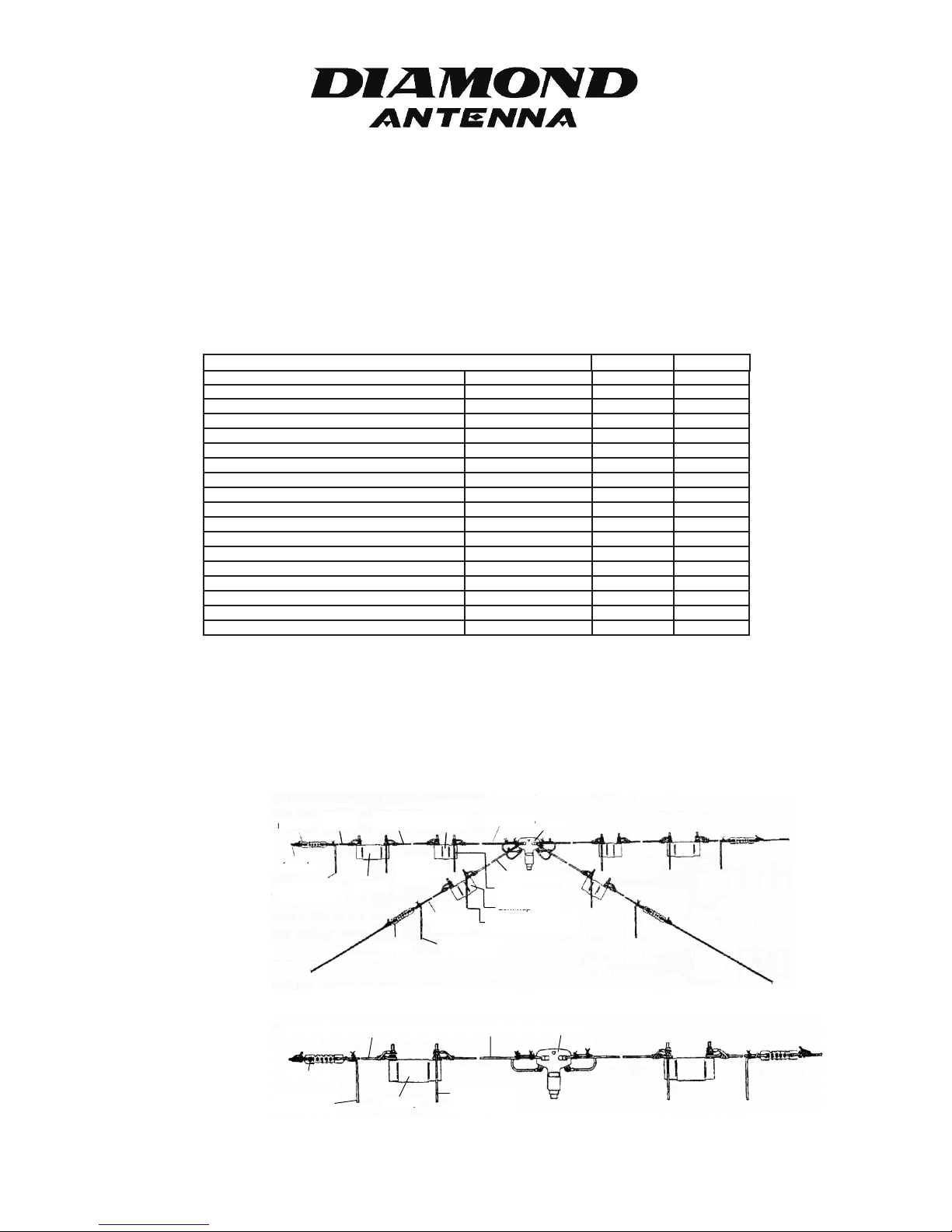
HF Multi-band Wire Dipole (Trap Dipole) Antennas
Insulator
Wire
Element C
Wire
Element B
40m Tr ap
Wire element A
Balun
Nylon rope
80m adjustment
element
80m Tr ap
Wire element D
15m adjustment
element
20m Tr ap
10m adjustment element
Wire
Element E
20m adjustment
element
Insulator
eerWirWi
t Ae elemenir
t C
40m T
elemen
Elemen
or
t
ope
ap
t
nsula
I 20m adjustmen
Wi
r
0m T
elemen
t
80m adjustmen
ylon r
t BElemenElemen
ap
t A
t D
t
t
t E
elemen
t20m adjustmen
Elemen
er
t elemen
ap
r
20m T
telemen
t
e elemenirW
e elemenir
r40m T
Nylon rope Wire element G Wire element F Balun
Insulator
80m adjusment
element
80m trap
40m adjustment
element
t G
or
t
ap
80m tr
elemen
80m adjusmen
tnsulaI
e elemenirW
ope
ylon r
Balun
telemen
t40m adjustmen
t Fe elemenirW
Diamond W-Series
W-8010 - 80m/40m/20m/15m/10m. Five Band Trap Dipole Antenna
W-735 - 80m/40m. Dual-Band Trap Dipole Antenna
Operation Instructions
Parts List
Each model contains the following parts. Please confirm all parts are accounted for before assembly.
BU-50 BALUN with two screws, nuts, and washers 1 1
80m Trap 2 2
0m Trap
4
2 20m Trap 2 Wire Element A 3.75m (12.3ft) 2 -
ire Element B
W
ire Element C
W
.2m (13.8ft)
4
.8m (9.2ft)
2
2 -
2 Wire Element D 2.8m (9.2ft) 2 Wire Element E 1.4m (4.6ft) 2 -
ire Element F
W
ire Element G
W
0.95m (35.9ft)
1
.9m (9.5ft)
2
- 2
- 2
Wire Element H 3.75m (12.3ft) - Wire Element I 3.4m (11.2ft) - Adjustment Element 0.4m (1.3ft) 6 2
Insulator 4 2
Nylon Rope 10m (32.8ft) 2 1
Self-melting plastic sealing tape 0.3m (1.0ft) 1 1
Binding wire 0.6m (2.0ft) 2 1
Description
W-8010 W-735
(1) The W-Series antennas are very easy to assemble. With 10 guage stranded plastic coated wire with low stretch ratio for elements.
(2) Adjustment elements are provided to adjust each band without affecting the rest of the bands.
(3) A completely molded wideband balun enables perfect weather proof performance.
Assembled antennas
W-8010
W-735
Fig.1
Fig. 2
1
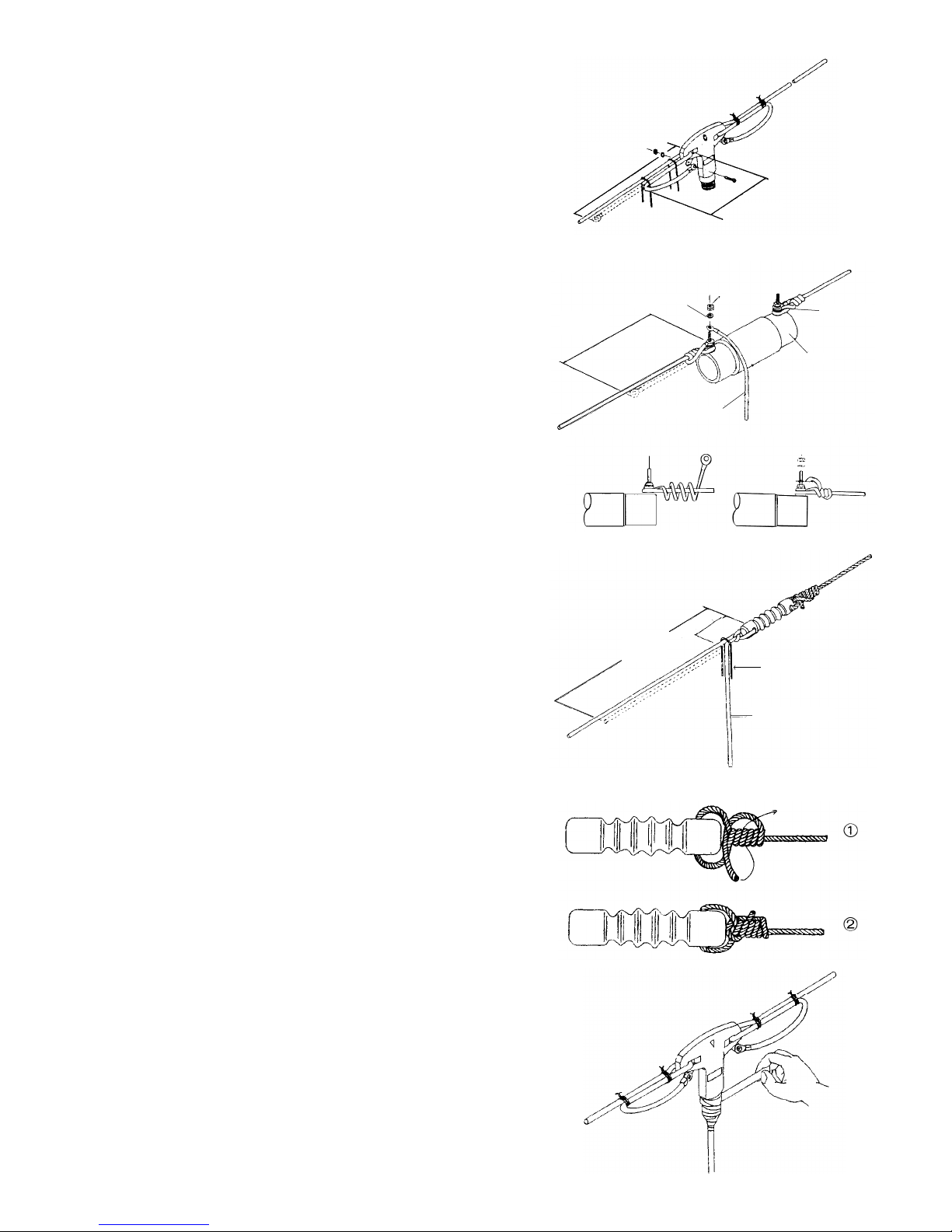
Assembly
20cm(7.9”)
7
cm(2.8”)
20cm(7.9”)
7
cm(2.8 )
15-16cm
(
5.9”-6.3”)
S
pring washer
Adjustment element
Trap
W
ire holder
(
5.9”-6.3”)
a
sher
t
i
ng
djustmen
i
ng w
S
pr
15-16cm
e
holder
p
i
r
a
Tr
5
5
c
m(2
1
.
7
”
)
5cm
(2.0”
)
Binding wire
Adjustment element
5
5
c
m(2
1
.
7
”
)
(2.0”
)
e
tt elemendjustmenA
The antennas are assembled as shown per figures.
1. Turn wire element approximately 20cm (7.9”) through balun and
bind two parts by binding wire as shown per Fig.1. In case of the W8010, two wire elements for one side are bound together.
Note: Cut binding wire for approximately 10cm (3.9”) each to bind.
2. To install a trap, turn a wire element approximately 15-16cm (5.9”-
6.3”) and then hook the element to wire holder section of the trap and
turn crimped terminal side of the element four times around the other
side of the element. Put crimped terminal through wire holder and fix
with nut and spring washer. (each adjustment element is to be set at
balun side of each trap.)
3. To install a insulator, put a element approximately 55cm (21.7")
through the insulator and tie the element once as shown per
Fig.3. Then bind the element with binding wire as shown per Fig.3.
Note : Since each wire element is being affixed with its own cord.
assemble the antenna by referring to each assembled antenna figure.
Note : Set adjustment element downward to avoid effecting reso-
nant frequency of the main element. And at insulator section at both ends. rest of 55cm (21.7') turned back becomes an adjustment element.
Note : Tie an insulator and nylon rope firmly as shown per Fig 4.
Fig. 1
Fig. 2
4. Finally, connect 50Q coaxial cable to the balun.To make con
nector Section waterproof, wrap around self-melting adhesive
plastic tape supplied by stretching it about two times. Then wrap
around conventional plastic tape to ensure it.(Fig 5)
Installation
There are various ways of installing the antenna depending on
the place where it is installed. In any case, take the following
points into account.
1. Since maximum voltage occurs at both ends of the antenna in
transmission, touching these points may lead to electric shock.
And it is recommended to locate both ends of the antenna al
least 1 to 2m (3.3'to 6.6') away from a building wall to avoid
spark noise which may cause TVl.
2. If the antenna is installed the way it is shown in Fig.B or D. to
avoid having direct load from coaxial cable, turn a coaxial cable
around the balun once and fix with a plastic tape. Set coaxial
cable away from the element to avoid causing bad VSWR or
unstable VSWR.
3. If the antenna is installed between two trees, to avoid breaking
the element by strong wind, it is recommended to pul elastic material such as rubber band or coil spring at the both ends of the
element.
4. Since antenna adjustment has to be practiced at the place where
the antenna is being operated, it is useful to make the antenna
up and down easily. It is also useful get rid of earth effect if the
antenna is installed as a horizontaldipole antenna, for the height
of the antenna is related with propagation impedance of the an-
tenna.
Fig. 3
Fig.4
Fig.5
2
 Loading...