

Page 1

DA425EA: 99900679: i19990121
Model DA425EA
Underhood Air Compressor
(Replaces Model HD750)
IOWA MOLD TOOLING CO., INC.
BOX 189, 500 HWY 18 WEST, GARNER, IA 50438
TEL: 515-923-3711
TECHNICAL SUPPORT FAX: 515-923-2424
MANUAL PART NUMBER 99900679
Page 2
DA425EA: 99900679: ii
19980521
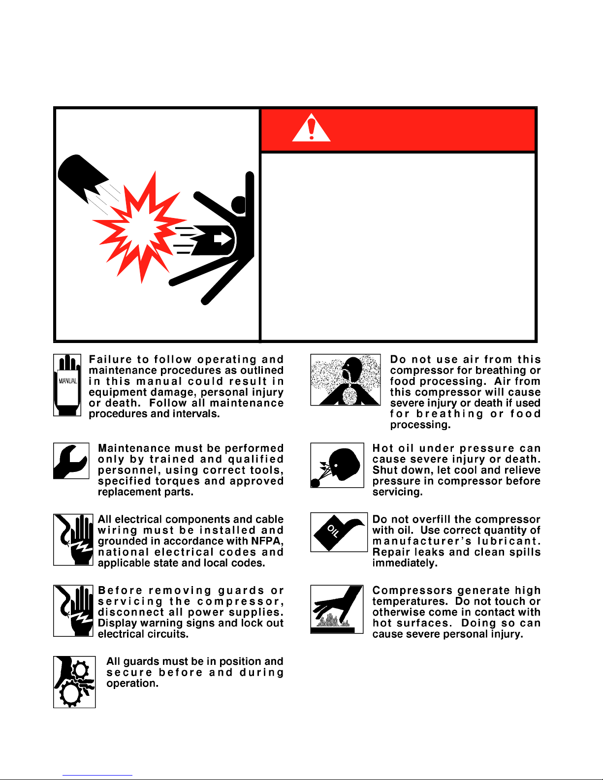
PRECAUTIONS
Read before operating your compressor!
DEATH, SERIOUS INJURY
●
Drain air tank after each use to prevent
moisture build-up and corrosion which
leads to tank failure.
●
Assure that tank and compressor relief
valves work properly, and are at correct
71393886
pressure settings.
●
DO NOT modify or repair air tank.
●
NEVER drive vehicle with pressure in air
tank.
DANGER
EXPLODING T ANK WILL CAUSE
OR PROPERTY DAMA G E
Page 3

DA425EA: 99900679: iii19980223
PARA TITLE PAGE
SPARE PARTS LIST
Section 1. SPECIFICA TIONS
1-1. GENERAL ................................................................................................ 1-1
1-2. SPECIFICATIONS.................................................................................... 1-1
Section 2. INST ALLATION
2-1. GENERAL ................................................................................................ 2-1
2-2. AIR COMPRESSOR................................................................................. 2-1
2-3. UNDERDASH SWITCH ............................................................................ 2-1
2-4. UNDERHOOD SWITCH........................................................................... 2-1
Section 3. OPERA TION
3-1. GENERAL ................................................................................................ 3-1
3-2. OPERATION ............................................................................................ 3-1
Section 4. MAINTENANCE & P ARTS
4-1. GENERAL ................................................................................................ 4-1
PRESSURE SWITCH INSTALLATION INSTRUCTIONS......................... 4-5
Section 5. REP AIR
5-1. GENERAL ................................................................................................ 5-1
5-2. PISTON RING REPLACEMENT .............................................................. 5-1
5-3. OIL PUMP REPLACEMENT..................................................................... 5-2
5-4. CRANKSHAFT AND BEARING REPLACEMENT.................................... 5-2
5-5. CLUTCH REPLACEMENT....................................................................... 5-3
5-6. TROUBLESHOOTING ............................................................................. 5-4
TABLE OF CONTENTS
LIST OF ILLUSTRATIONS
FIGURE TITLE (PART NUMBER) PAGE
A-1. OUTSIDE DIMENSIONS.......................................................................... 1-1
C-1. AUTOMATIC SPEED CONTROL OPTION............................................... 3-1
D-1. ROUTINE MAINTENANCE CHECKLIST ................................................. 4-1
D-2. AIR COMPRESSOR - PARTS (51711330)............................................... 4-2
D-2A. AIR COMPRESSOR - P ARTS (5171 1330)............................................... 4-3
D-2B. AIR COMPRESSOR - P ARTS (5171 1330)............................................... 4-4
D-3. PRESSURE SWITCH KIT & INSTALLATION INSTR (51710224) ............ 4-5
D-4. OPTION-SOLBERG AIR FILTER KIT (51709435).................................... 4-6
D-5. OPTION-AIR FILTER KIT (95709998)...................................................... 4-6
REPAIR KITS ........................................................................................... 4-6
E-1. PISTON RING ORIENTATION ................................................................. 5-1
E-2. CYLINDER HEAD TORQUE SEQUENCE ............................................... 5-1
E-3. BEARING HOUSING TORQUE SEQUENCE .......................................... 5-3
E-4. ROD ALIGNMENT.................................................................................... 5-3
E-5. TROUBLESHOOTING CHART ................................................................ 5-4
Page 4

DA425EA: 99900679: iv19980223
RECOMMENDED SPARE PARTS LIST
1 Y ear Supply
DA425EA AIR COMPRESSOR
For Manual: 99900679
This spare parts list does not necessarily indicate that the items can be expected to fail in the course of a year. It is intended to
provide the user with a stock of parts sufficient to keep the unit operating with minimal down-time waiting for parts. There
may be parts failures not covered by this list. Parts not listed are considered as not being Critical or Normal Wear items
during the first year of operations and you need to contact the distributor or manufacturer for availability.
SHELF
ASSEMBLY
DESIGNATION
LIFE
(MO)
ORDER
QTYCODEQTYDESCRIPTIONPART NO.ITEM NO.
51711330.01.19970619 UNDERHOOD AIR COMPRESSOR
2 60025010 CYLINDER BLOCK 2 W
3 60025008 CYLINDER HEAD 2 W
5 70073031 VALVE PLATE 2 C
18 76039141 AIR INTAKE FILTER-FOAM 2 P
33 76393802 FILTER SCREEN 4 P
44 51704023 INSERT ASM 1 C
66 51029296 CONNECTING ROD 4 W
84 51704321 CRANKSHAFT ASM 1 W
87 51014947 RING SET 1 W
92 70056437 PULLEY- 1 GROOVE 1 C
70056304 PULLEY- 2 GROOVE 1 C
70056441 PULLEY- 6 GROOVE 1 C
70056442 PULLEY- 7 GROOVE 1 C
93 77044419 CLUTCH FIELD 1 C
REF 51039013 GASKET SET 1 C
REF 77041369 PRESSURE SWITCH 1 C
REF 51086090 OIL-2 QTS 2 P
Page 5
DA425EA: 99900679: 1-119951003
SECTION 1. SPECIFICATIONS
1-1. GENERAL
The IMT DA425EA air compressor is an underhood,
engine mounted, single stage, air cooled, 4-cylinder,
pressure lubricated unit, with a delivery rate of 25
CFM at 1400 RPM.The compressor is belt driven
from the engine crankshaft, through a magnetic
clutch. It is engaged and disengaged by use of an air
pressure sensing, electric switch. The pressure
switch is preset on factory installed units at
approximately 120 PSI to engage, and 150 PSI to
disengage.
CAUTION
OPERATING THE COMPRESSOR AT PRESSURES
ABOVE 150 PSI WILL SHORTEN THE SERVICE LIFE
AND VOID THE WARRANTY.
1-2. SPECIFICATIONS
Bore 2-5/8"
Stroke 2"
Cylinder Configuration V4
Displacement 35 CFM*
Delivery 25 CFM*
Lubrication Oil Pump
Oil Capacity 1-1/3 qts
Cooling Air
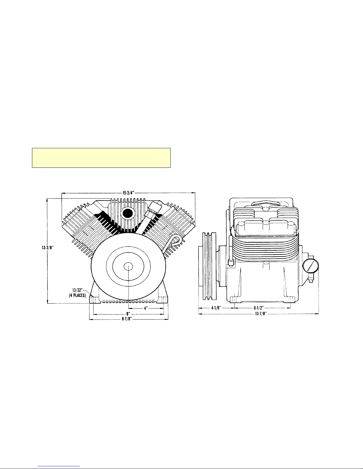
Height 13-3/8"
Width 15-3/4"
Length 13-7/8"
Material Aluminum Alloy
Weight 75 lbs.
* @ 1400 RPM - 100 PSI
FIGURE A-1. OUTSIDE DIMENSIONS
Page 6

DA425EA: 99900679: 2-119951003
SECTION 2. INSTALLATION
2-1. GENERAL
This section pertains to the installation of the IMT
DA425EA compressor and related components.
Because installations will vary somewhat, dependent
on the chassis, it will describe the installation in
general terms only.
2-2. AIR COMPRESSOR
Each installation will differ dependent on the chassis
make, model, year of manufacture, and optional
equipment. Refer to the mounting kit for specific
information relating to your application.
2-3. UNDERDASH SWITCH
The installation kit will include the correct bracket
for the installation of the compressor, power switch
and the engine speed control. The bracket may
house switches for other functions, depending on the
total system.
1. Drill mounting holes in the underside of the dash.
It may be possible to utilize existing holes.
2. Install the switch, or switches, needed for your
installation.
2-4. UNDERHOOD SWITCH
The purpose of the underhood switch is to prevent
the compressor from running unless the vehicle’s
hood is raised. This will ensure sufficient air flow to
the compressor during operation.
1. Select a location for the mercury switch that will
provide protection for the glass envelope and keep
the switch contacts open when the hood is closed.
The mercury should not be in contact with the
contacts to accomplish this.
2. Drill a 1/16 inch hole in the desired location and
install the switch bracket. Install the switch in the
bracket. Connect one lead to the underdash switch,
the other to the compressor pressure switch. When
wired properly , the switch in the cab must be “ON”
and the hood must be raised in order for the
compressor to operate.
CAUTION
WARRANTY ON THE COMPRESSOR WILL BE VOID IF
THE UNDERHOOD SAFETY SWITCH IS NOT USED.
FAILURE TO USE THIS SWITCH WILL ALLOW THE
COMPRESSOR TO OPERATE WITH THE HOOD
CLOSED AND WILL CAUSE OVERHEATING.
3. Route the needed wiring harness to the rear of the
bracket and connect to the proper switches.
4. Securely fasten the assembled switch bracket to
the dash with bolts, nuts, and washers provided.
NOTE
IF THE DASHBOARD IS PLASTIC, THE GROUND WIRE
MUST BE CONNECTED TO CHASSIS GROUND. THE
PLASTIC DASHBOARD IS NOT CONDUCTIVE AND
WILL NOT PROVIDE A GROUND.
5. Connect the positive side of the compressor
switch to the power switch. Connect the other side
of the switch to the underhood safety switch and the
indicator lamp.
6. Install the throttle cable mounting bracket to the
underside of the dash, near the switch bracket.
Install the cable and connect to the carburetor
linkage. Make certain that there is enough free play
to allow the engine to return to normal idle.
Page 7

DA425EA: 99900679: 3-119951003
SECTION 3. OPERATION
3-1. GENERAL
Each compressor is bench tested under load at the
factory to ensure proper break-in and operation.
While it is not necessary to follow any break-in
procedure, the following checks should be made
before putting the unit into service, as well as,
periodically during use.
1. Before start-up:
A. Check the oil level in the compressor crankcase
with the dipstick on the unit. If oil is needed, use
only IMTs synthetic compressor oil.
B. Check the air intake filter pads on each head to
make certain that they are clean and unobstructed.
Dirty filters are a possible cause of reduced air
output.
3-2. OPERATION
To use the compressor, raise the hood to provide
adequate ventilation, start the vehicle engine, and
engage the compressor by operating the compressor
switch in the cab. On systems without automatic
engine speed control, adjust the engine RPM with
the manual throttle cable to maintain the proper
RPM setting while the compressor is pumping.
The system will now function automatically. It will
engage the compressor clutch when the air pressure
is below 120 psi, and disengage when the air
pressure reaches 150 psi.
NOTE
ON UNITS WITH MANUAL ENGINE SPEED CONTROL,
THE ENGINE RPM WILL INCREASE WHEN THE
COMPRESSOR CLUTCH DISENGAGES.
2. With the compressor engaged:
On units having the automatic speed control option,
check the engine RPM for proper setting (1400
RPM max.) under compressor load.
CAUTION
THIS UNIT IS EQUIPPED WITH AN UNDERHOOD
SAFETY SWITCH WHICH REQUIRES THA T THE HOOD
BE RAISED WHILE THE COMPRESSOR IS IN
OPERATION. THIS IS INSTALLED TO ENSURE THAT
THE UNIT HAS ADEQUATE VENTILATION, AND THAT
THE UNIT IS NOT INADVERTANTLY LEFT ON WHEN
NOT IN USE AND THE VEHICLE IS IN MOTION.
BYPASSING THIS SAFETY DEVICE, OR OPERATING
THIS UNIT IN EXCESS OF 1400 RPM, WILL VOID THE
WARRANTY, AND WILL SHORTEN THE NORMAL
SERVICE LIFE OF THE COMPRESSOR.
Page 8

DA425EA: 99900679: 3-219930125
Page 9
DA425EA: 99900679: 4-119951003
Section 4. MAINTENANCE & PARTS
4-1. GENERAL
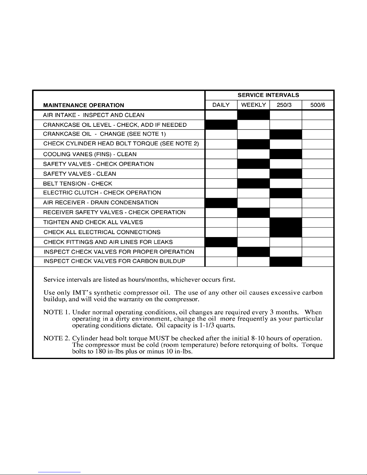
The following table is a list of routine maintenance
items, including service intervals. It also includes a
parts list and assembly drawing of the compressor.
FIGURE D-1. ROUTINE MAINTENANCE CHECKLIST
Page 10

DA425EA: 99900679: 4-219970619
FIGURE D-2. DA425EA UNDERHOOD AIR COMPRESSOR (51711330-1)
ITEM PART NO. DESCRIPTION QTY
1. 60025012 CRANKCASE (PART OF 83) 1REF
2. 60025010 CYLINDER BLOCK 2
3. 60025008 CYLINDER HEAD 2
4. 60025009 PULSATION TANK 1
5. 70073031 VALVE PLATE 2
6. 70073030 DIPSTICK 1
7. 70014613 DIPSTICK TUBE 1
8. 60120238 OIL SCREEN TUBE (PART OF 83) 1REF
9. 60120289 OIL SCREEN (PART OF 83) 1REF
10. 72066008 OIL SCREEN CLAMP (PART OF 83) 1REF
11. 60101507 OIL FILL PIPE 1
12. 51705310 BREATHER CAP ASM (INCL:89,90) 1
13. 76393085 O-RING (PART OF 44&77) 1REF
14. 72053403 PLUG 3/8NPT SH (PART OF 83) 1REF
15. 72053413 PLUG 3/8NPT SQHD (PAR OF 83) 1REF
16. 70039300 IDENT PLATE 1
17. 70014626 AIR FILTER CLIP 8
18. 76039141 AIR INTAKE FILTER-FOAM 2
19. 73054026 DRAIN COCK 1
20. 72053406 PLUG 1NPT SH 1
21. 72060032 CAP SCR 5/16-18X2-3/4 12
22. 72060062 CAP SCR 7/16-14X1 4
23. 72060025 CAP SCR 5/16-18X1 HHGR5 12
24. 72063001 WASHER 1/4 WRT 12
25. 70024122 WASHER 5/16 FLAT COPPER 12
26. 72063052 WASHER 7/16 LOCK 4
28. 7Q072212 O-RING 2
29. 76039113 HEAD GASKET 2
30. 76039114 GASKET-CYL BLOCK/VLV PLT 2
31. 76039111 GASKET-CRNKCASE/CYL BLOCK 2
32. 60025229 MANIFOLD BLOCK (PART OF 79) 1REF
33. 76393802 FILTER SCREEN 4
36. 72053404 PLUG 1/2NPT SH(PART OF 79) 1REF
37. 72053405 PLUG 3/4NPT SH (PART OF 79) 1REF
38. 72053558 NIPPLE 3/4NPT X 2 1
39. 72053376 RED. BUSHING 3/4FPT 1MPT 1
40. 72053295 STREET ELBOW 3/4NPT 90° 1
41. 60106933 PLUG 3/4MPT (PART OF 79) 1REF
42. 72066426 BALL 9/16 (PART OF 44) 1REF
43. 76393107 O-RING (PART OF 79) 1REF
44. 51704023 INSERT ASM 1REF
45. 72661487 DRIVE PIN 1
47. 76039119 SEAL (PART OF 81) 1REF
48. 60025007 FRT BRG HSG (PART OF 81) 1REF
49. 70055011 FRT CUP BEARING (PART OF 81) 1REF
50. 70055012 FRT CONE BEARING (PART OF 84) 1REF
51. 60101271 CRANKSHAFT 1
52. 72066267 WOODRUFF KEY #6 1
53. 70055009 REAR CONE BRG (PART OF 84) 1REF
54. 60101269 OIL PUMP COLLAR 1REF
ITEM PART NO. DESCRIPTION QTY
55. 72066307 DRIVE PIN (PART OF 84) 1REF
56. 70055010 REAR BRG CUP (PART OF 82) 1REF
57. 60025005 REAR BRG HSG (PART OF 82) 1REF
58. 70014583 COIL SPRING 1
59. 60101505 SLEEVE 1
60. 70051006 OIL PUMP 1
61. 60025006 PUMP COVER 1
63. 72053411 PLUG 1/8NPT SQHD 2
64. 72060731 SCR 5/16-18X3/4 SH (PART OF 83) 5REF
65. 72060731 SCR 5/16-18X3/4 4
66. 51029296 CONNECTING ROD 4
67. 70029062 PISTON (PART OF 88) 4REF
68. 70014627 PISTON PIN (PART OF 88) 4REF
69. 72066018 RETAINING RING (PART OF 88) 8REF
70. 70014600 OIL RING (PART OF 87) 4REF
71. 70014599 COMPRESSION RING(PART OF 87) 8REF
73. 76039093 PUMP COVER GASKET 1
74. 76039112 FRT BRG HSG GASKET
(PART OF 83) 2REF
75. 72063050 WASHER 5/16 LOCK 1
76. 72053404 PLUG 1/2NPT SH 1
77. 70029593 INSERT (PART OF 44) 1REF
78. 7Q073017 O-RING (PART OF 44) 1REF
79. 51704827 MANIFOLD CHECK VALVE ASM
(INCL:32,36,37,41-44,77,78) 1
81. 51705709 FRT BRG HSG ASM
(INCL:47-49,PART OF 83) 1REF
82. 51705710 REAR BRG HSG ASM
(INCL:56,57,PART OF 83) 1REF
83. 51705811 CRANKCASE/CRANKSHAFT ASM 1
84. 51704321 CRANKSHAFT ASM
(INCL:50,51,53-55,PART OF 83) 1REF
85. 72063050 WASHER 5/16 LOCK (PART OF 83) 5REF
86. 72060025 CAP SCR 5/16-18X1(PART OF 83) 5REF
87. 51014947 RING SET (INCL:70,71) 1
88. 51029285 PISTON ASM (INCL:67-69) 4
89. 60107276 CAP 1/2HEX MOD (PART OF 12) 1REF
90. 70048080 BREATHER 1/4NPT (PART OF 12) 1REF
91. 70039124 OIL FILL DECAL 1
92. 70056437 PULLEY 1-GROOVE 5/8" 1REF
70056304 PULLEY 2-GROOVE 1/2" 1REF
70056441 PULLEY 6-GROOVE SERPENTINE 1REF
70056442 PULLEY 7-GROOVE SERPENTINE 1REF
93. 77044419 CLUTCH FIELD 1
94. 72066537 J-CLIP .19 VINYL 2
95. 70732444 CLUTCH HARDWARE KIT 1
100. 70029468 SHIM (PART OF 44) 1REF
101. 76039092 REAR BRG GASKET .006 AR
76039094 REAR BRGGASKET .010 AR
76039143 REAR BRG GASKET ,015 AR
76039144 REAR BRG GASKET .020 AR
Page 11
DA425EA: 99900679: 4-319980521
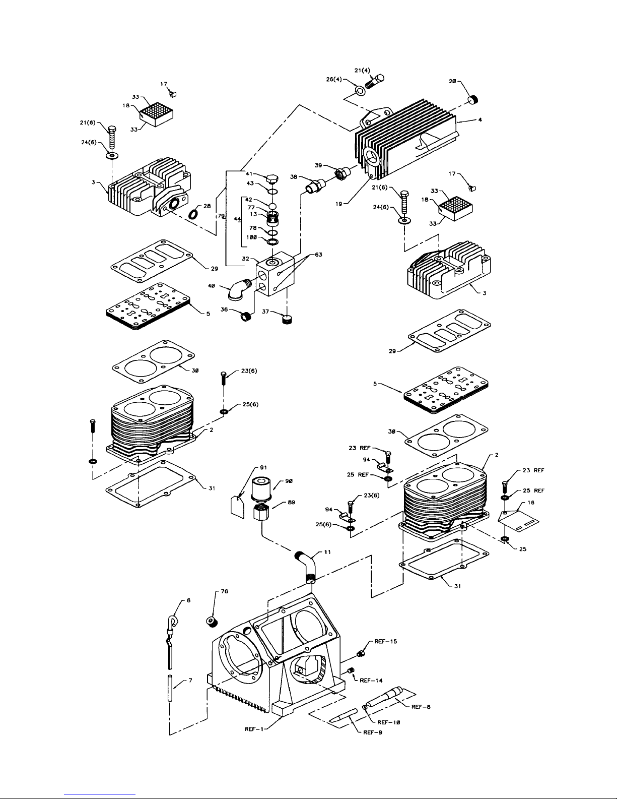
FIGURE D-2A. DA425EA UNDERHOOD AIR COMPRESSOR (51711330-2)
Page 12
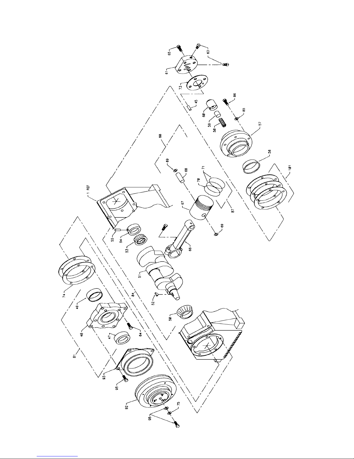
DA425EA: 99900679: 4-419970619
FIGURE D-2B. DA425EA UNDERHOOD AIR COMPRESSOR (51711330-3)
Page 13
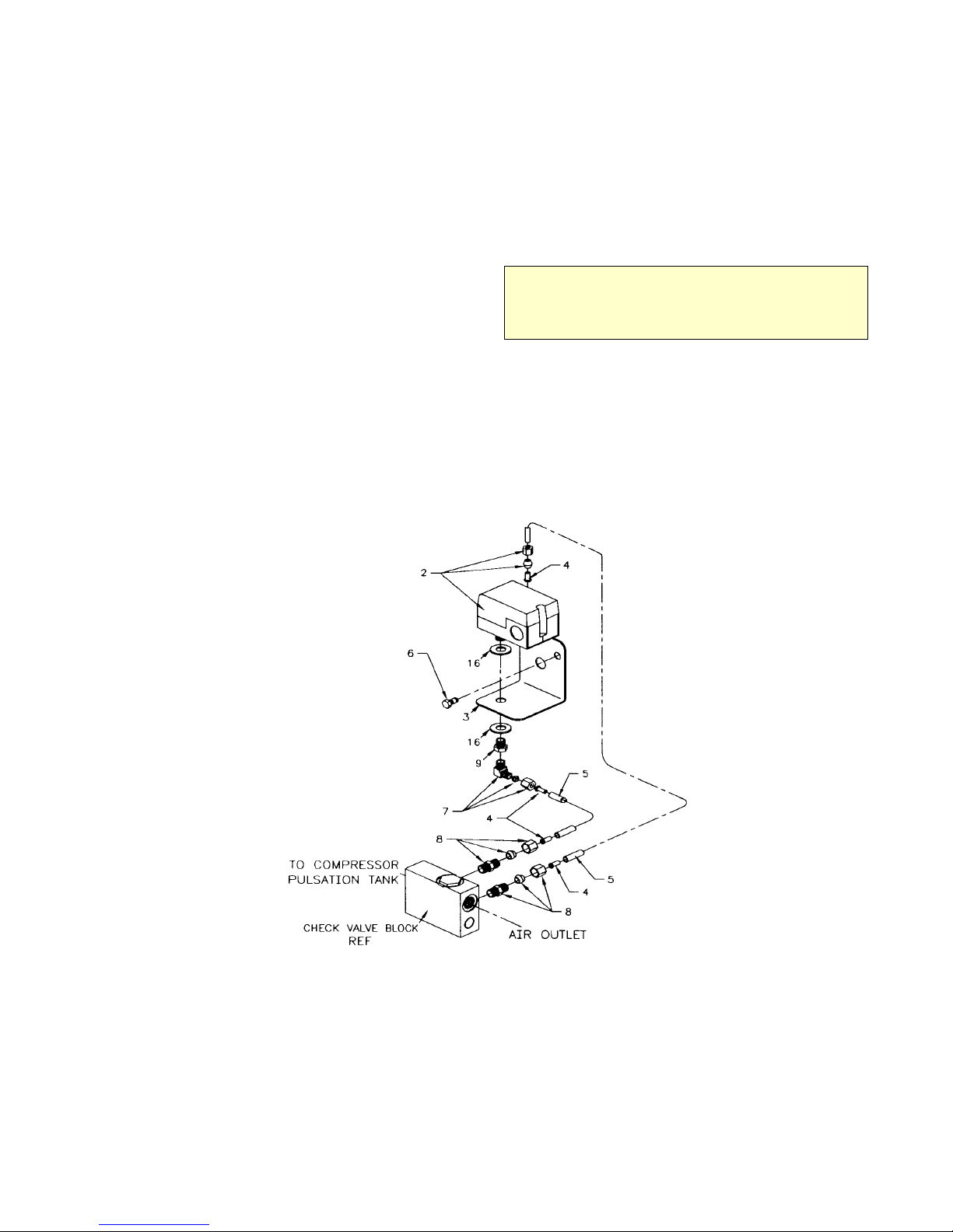
DA425EA: 99900679: 4-519960802
REMOTE MOUNTED PRESSURE SWITCH
INST ALLATION INSTRUCTIONS (99900501)
4. Install the 1/8-1/4 adapter (72053832) in the
check valve block and attach the 1/4" airline hose.
1. Locate pressure switch mounting bracket
(60119843) to the firewall or fender well of truck. Use
the predrilled holes on the mounting bracket as a
pattern to drill holes when mounting.
2. Assemble pressure switch and related hardware
to the mounting bracket. Attach a 90° brass elbow
(72531042)to the bottom side of the pressure switch
mounting bracket.
3. Mount the pressure switch mounting bracket to
the truck. Use the three (2) sheet metal screws
provided in the kit.
5. Continue assembly as shown on the installation
assembly drawing.
6. See Electrical Wiring Diagram provided with the
Pressure Switch Kit, for hook-up information.
NOTE
ON FORD LATE MODEL TRUCKS, MOUNTING
BRACKET (60119843) CAN BE LOCATED ON THE
PASSENGER SIDE OF THE RADIATOR AT TOP. USE
EXISTING BOLTS.
ITEM PART NO. DESCRIPTION QTY
1. 51710224 KIT-RMT PR SW (INCL:2-17) 1
2. 77041369 PRESSURE SWITCH 1REF
3. 60119843 MOUNTING BRACKET 1REF
4. 72532952 BRASS INSERT 4REF
5. 89034176 AIR LINE 1/4" (10 FT) REF
6. 72061004 SHT MTL SCR #14X3/4 2REF
7. 72531042 ELBOW 1/8-1/4NPT 90° 1REF
8. 72053832 ADAPTER 1/8MPT 1/4CPRSNFTG 2REF
9. 72531826 REDUCER BUSHING 1/4-1/8NPT 1REF
FIGURE D-3. PRESSURE SWITCH KIT & INSTALLATION INSTRUCTIONS (51710224)
ITEM PART NO. DESCRIPTION QTY
10. 89044274 WIRE 14GA BLK (4 FT) REF
11. 89044271 WIRE 14GA BLU (4 FT) REF
12. 89044234 WIRE 14GA YEL (4 FT) REF
13. 77040051 TERMINAL SPADE 16-14GA 3REF
14. 89034048 SPIRAL WRAP (7") REF
15. 89034176 AIR LINE 1/4" (5 FT) REF
16. 72063005 WASHER 1/2 WRT 2REF
17. 99900169 WIRING DIAG-COMPRESSOR 1REF
Page 14
DA425EA: 99900679: 4-619960708
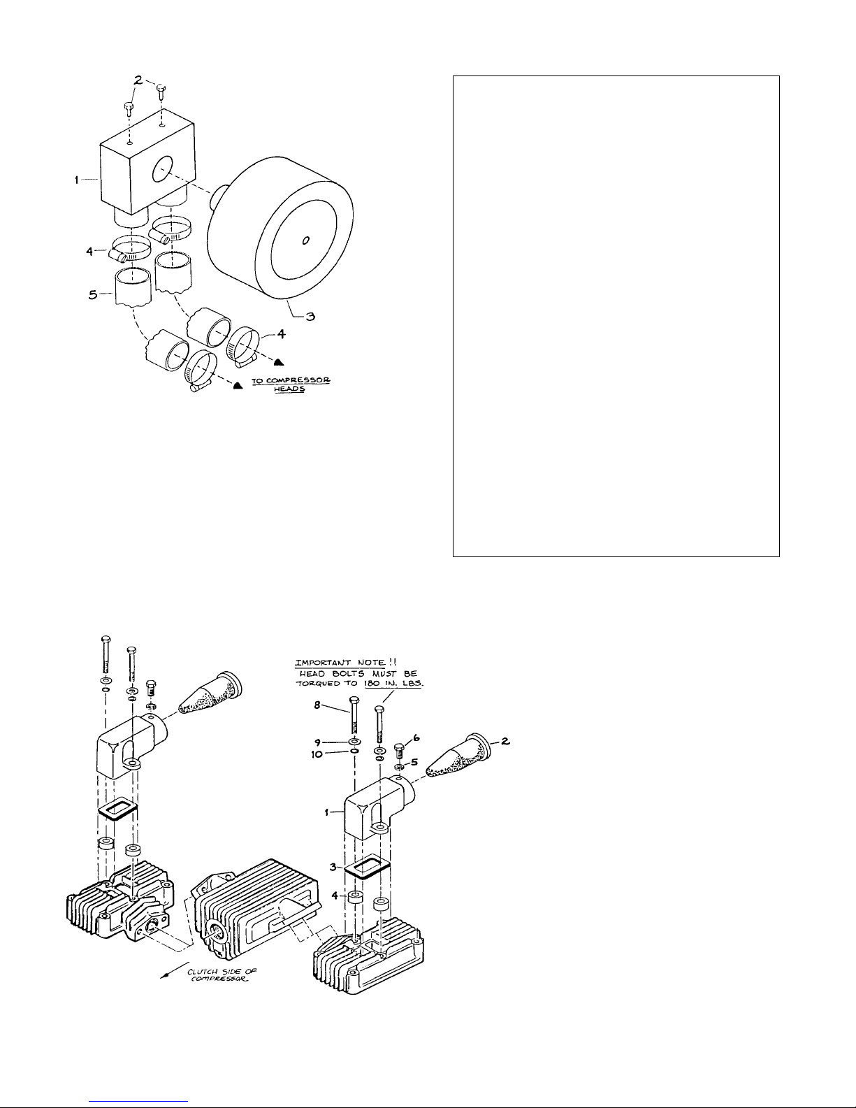
ITEM PART NO. DESCRIPTION QTY
1. 51707706 AIR INTAKE MANIFOLD ASM 1
2. 72061004 SHT MTL SCR #14X3/4 2
3. 70048007 SOLBERG FILTER 1
4. 72066001 HOSE CLAMP #24 4
5. 76391332 HOSE 2
FIGURE D-4. OPTION-SOLBERG AIR FIL TER KIT
(51709435)
REPAIR KITSGASKET KIT - 51039013
7Q072212 O-RING - CYL HEAD 2
76039092 GASKET-REAR BRG HSG .006 2
76039093 GASKET-PUMP COVER 1
76039094 GASKET-REAR BRG HSG .010 2
76039111 GASKET-CYL BLOCK BOTTOM 2
76039112 GASKET-FRT BRG HSG 2
76039113 GASKET-V A L VE COVER 2
76039114 GASKET-CYL BLOCK TOP 2
76039119 SEAL 1
76039143 GASKET-REAR BRG HSG .015 2
76039144 GASKET-REAR BRG HSG .020 2
CHECK VALVE KIT - 51704358
7Q073017 O-RING 1
70029377 CHECK VALVE INSERT 1
70029468 SHIM .53 ID X .94 OD X .005 THK 1
72066426 BALL .594 DIA 1
76393085 O-RING 1
CRANKSHAFT KIT - 51070708
51705655 CRANKSHAFT ASM
(INCL: KEY & CRANK) 1
70055010 BEARING-REAR CUP 1
70055011 BEARING-FRT CUP 1
70055012 BEARING-FRT CONE 1
70055009 BEARING-REAR CONE 1
72066307 DRIVE PIN 1
60101269 OIL PUMP COLLAR 1
PISTON RING SET - 51014947
70014599 COMPRESSION RING 8
70014600 OIL RING 4
FIGURE D-5. OPTION-AIR FIL TER KIT (95709998)
ITEM PART NO. DESCRIPTION QTY
1. 70029546 BREATHER MANIFOLD 2
2. 70048117 AIR FILTER CONE 2
3. 76392274 GASKET 2
4. 60106236 SLEEVE 4
5. 72063049 WASHER 1/4 LOCK 2
6. 72060270 CAP SCR 1/4-28X1/2 HHGR5 2
8. 72060035 CAP SCR 5/16-18X3-1/2 HHGR5 4
9. 72063001 WASHER 1/4 FLAT 4
10. 70024122 WASHER .33X.50X.03 COPPER 4
Page 15
DA425EA:99900679: 5-119951003
SECTION 5. REPAIR
5-1. GENERAL
This section describes the disassembly and assembly
procedures for the air compressor. In all cases,
remove the compressor from the frame, and provide
a clean work environment before proceeding with
disassembly. Refer to the parts drawing in section 4
of this manual for parts locations.
5-2. PISTON RING REPLACEMENT
1. Remove the pulsation tank.
2. Unscrew the head bolts and remove the heads.
NOTE
A RUBBER FACED MALLET WILL HELP WHEN
REMOVING THE HEAD. T AP THE SIDES OF THE HEAD
CAREFULLY UNTIL THE HEAD IS LOOSE. LIFT OFF
THE HEADS.
3. Remove the cylinder bolts. Tap the sides of the
cylinder several times to break it loose from the
gasket. Rock the cylinder back and forth and lift
until it is free. Lift it off the pistons.
9. Position the cylinder base gasket on the
crankcase. Use a few drops of oil to hold it in
position. Install the cylinder block spacer and gasket
on the crankcase.
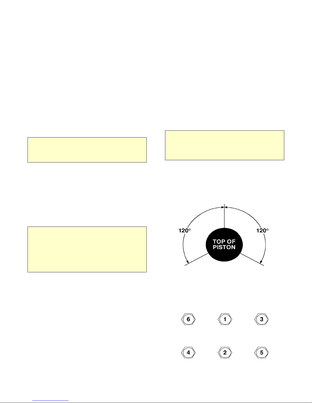
10. Rotate the rings so that the gaps of the three
rings are 120° apart. Lightly lubricate the inside of
the cylinder. Rotate the crankshaft so that a piston is
at the top of the stroke. Compress the rings with a
ring compressor, and slide the cylinder over the
piston. Repeat for the other piston.
CAUTION
DO NOT LUBRICATE THE RINGS. USE A LIGHT
LUBRICANT , SUCH AS WD-40 ONL Y, ON THE CYLINDER
WALLS. OILING THE RINGS WILL PREVENT THEM
FROM SEATING AND CAUSE EXCESSIVE OIL
CONSUMPTION.
4. Use a single edged razor blade, or sharp putty
knife, to remove the old gasket material.
CAUTION
DO NOT ALLOW THE GASKET MA TERIAL TO FALL INTO
THE CRANKCASE. DO NOT NICK THE HEAD,
CYLINDER, OR CRANKCASE MATING FACES WHILE
REMOVING THE OLD GASKET. REMOVE ALL OF THE
OLD GASKET MATERIAL TO PROVIDE A SMOOTH,
CLEAN SURFACE FOR THE NEW GASKET. FAILURE
TO FOLLOW THIS PROCEDURE MAY RESULT IN THE
NEED TO RESEAL THE UNIT LATER.
5. Hone the cylinder to break the glaze and to
remove the buildup at the top of the cylinders.
6. Measure the inside diameter of the cylinder for
roundness and excessive wear. The bore should be
2.625" (0.0025" tolerance). If the bore is oversized,
the cylinder must be replaced.
7. With a ring expander, remove the compression
and oil rings.
FIGURE E-1. PISTON RING
ORIENT A TION
8. With the ring expander, install the new ring kit.
Make certain that the oil ring is on the bottom and
the beveled inside edge of the compression ring is
toward the top of the piston.
FIGURE E-2. CYL HEAD TORQUE
SEQUENCE
Page 16

DA425EA:99900679: 5-219951003
11. Slide the cylinder down until it mates with the
crankcase. Start all cylinder mounting bolts, until
they are snug. Torque the bolts to 180 inch pounds in
the sequence shown. Do not torque to the full 180
inch pounds all at once. Torque in 25-50 pound
increments.
7. Insert the two remaining bolts and torque to 180
inch-pounds. The bolts should be torqued in a
diagonal pattern.
8. Install the air compressor On the frame.
Connect the air lines and wiring.
12. Position the gaskets and valve plate on top of the
cylinder. Position the head on the cylinder and turn
all studs finger tight. Torque the studs/nuts to 240 inlbs in 25-50 pound increments
NOTE
INSTALL THE VALVE PLATE WITH THE MARKED
SURFACE F ACING UP.
13. Install the pulsation tank, and torque to 180
inch-pounds.
14. Install the compressor, connect the wiring and
the air lines. Test the unit.
NOTE
IF PRESSURE FAILS TO BUILD AND THE
COMPRESSOR IS EXCESSIVEL Y NOISY, CHECK THE
V ALVE PLA TE. IT MA Y HA VE BEEN INST ALLED UPSIDE
DOWN.
5-3. OI L PUMP REPLACEMENT
1. Remove the bolts and lift off the pump cover.
5-4. CRANKSHAFT AND BEARING
REPLACEMENT
If it is necessary to replace the crankshaft, related
components must also be replaced. Replace both
bearings, both races, the key, pump collar and pump
drive pin.
NOTE
DEPENDING ON THE CONDITION OF THE
CRANKSHAFT, BEARING MAY BE REPLACED
WITHOUT REPLACING THE CRANKSHAFT . REPLACE
THE BEARING RACES WHENEVER THE BEARINGS
ARE REPLACED.
1. Remove the pulsation tank, both heads, cylinders,
and pistons. Refer to the instructions in section 5,
paragraph 2.
2. Remove the bolts on the connecting rods, and lift
them out. Reassemble the connecting rods to be
certain that the matched parts remain together on the
same crankshaft journals.
2. With a single edged razor blade, or sharp putty
knife, remove the old gasket material. Take care not
to damage the machined surfaces.
3. Lift the pump out of the cavity.
4. Position a new gasket on the rear bearing
housing.
5. Insert the pump into the cavity. Position the
pump slightly to one side, using acommon
screwdriver. Wedge the pump into position so that it
partially compresses the spring. Note that the driver
pin and slot in pump must be in line.
6. Place the pump cover into position and start two
bolts (bolts must be diagonally opposed). Strike the
pump cover with a rubber faced mallet to jar the
pump loose. When the tension spring can be felt
against the pump cover, the pump is loose.
3. Remove the pump cover, oil pump, sleeve,
spring, and rear bearing housing.
4. Remove the clutch and pulley assembly, and the
front bearing housing.
5. Pull the crankshaft from the crankcase.
6. Remove all gasket material with a single edged
razor blade, or sharp putty knife.
CAUTION
DO NOT GOUGE THE MACHINED SURFACES WHEN
REMOVING THE GASKETS. THIS MA Y CAUSE LEAKS.
7. Press the bearing races out of the bearing
housing.
8. Press the tapered roller bearings off of the
crankshaft if only the bearings are being replaced. If
the crankshaft is to be replaced, discard the entire
assembly.
9. Press the new bearings into position.
Page 17

DA425EA:99900679: 5-319951003
NOTE
THE CRANKSHAFT SHOULD HAVE NEW BEARINGS
INST ALLED. IF NOT , PRESS THE NEW BEARINGS INTO
POSITION ON THE CRANKSHAFT .
10. Generously oil the front bearing race and install
the front bearing housing with gasket. Torque the
bolts to 180 inch- pounds. Torque the bolts as shown
in the pattern below.
FIGURE E-3. BRG HSG TORQUE SEQUENCE
11. Slide the crankshaft into the crankcase.
Generously lubricate the bearing race and install the
rear bearing housing and gaskets.
14. Install the pistons, rings, heads and pulsation
tank.
5-5. CLUTCH REPLACEMENT
CAUTION
CLUTCH FAILURE MA Y BE DUE T O A LEAKING CHECK
VA LVE. MAKE CERT AIN THA T THE CHECK VA LVES ARE
FUNCTIONING PROPERLY BEFORE INST ALLING THE
NEW CLUTCH. THE CHECK VALVES MAY BE
CHECKED BY PRESSURIZING THE TANK AND
SHUTTING OFF THE COMPRESSOR. THERE SHOULD
BE NO AIR ESCAPING FROM THE UNLOADER VALVE.
IF THERE IS AIR ESCAPING, THE CHECK V AL VES ARE
FAUL TY .
The clutch assembly can be removed while the
compressor is still on the vehicle. The following
procedure should be used.
WARNING
ATTEMPTING TO START THE COMPRESSOR WHILE
THE CLUTCH IS BEING REMOVED WILL CAUSE
SERIOUS INJURY .
1. Turn on the ignition switch, and move the
compressor switch to the on position. This will
engage the clutch, and make for easier removal.
NOTE
GASKET KITS ARE SUPPLIED WITH TWO (2) EACH OF
.006, .010, .015, AND .020 GASKETS. USE THESE REAR
BEARING GASKETS IN ANY COMBINATION AND
QUANTITY TO LIMIT ALL PLAY FRONT TO REAR, BUT
STILL ALLOW THE CRANKSHAFT TO TURN FREELY.
12. Install the oil pump as indicated in section 5,
paragraph 3.
13. Install the connecting rods. Thoroughly oil the
crankshaft and rods before installing them. When
installing the rods, make certain that the tabs are
aligned on the same side of the rod as shown below.
2. Remove the bolt in the center of the pulley and
insert a 5/8-11 bolt.
3. Tighten the 5/8-11 bolt until the pulley is forced
off the crankshaft.
4. Loosen the drive belt and remove the
pulley.
NOTE
IF THE DRIVE BELT IS LOOSENED BEFORE THE
PULLEY IS LOOSE, IT WILL BE DIFFICULT TO HOLD
THE PULLEY STA TIONAR Y WHILE TIGHTENING THE
5/8-11 BOLT.
CAUTION
DO NOT USE A WHEEL PULLER ON THE OUTER RIM
OF THE PULLEY. THIS CAN RESULT IN DAMAGE TO
THE CLUTCH BEARING.
5. Remove the four (4) bolts holding the coil
assembly to the front of the compressor.
FIGURE E-4. ROD ALIGNMENT
Page 18
DA425EA:99900679: 5-419951003
To reinstall the clutch:
6. Connect the coil wire to the air pressure switch.
1. Position the magnetic coil assembly over the
front bearing housing and secure the assembly with
the 1/4-20 bolts. Torque to 85-120 inch-pounds.
2. Insert the woodruff key into the crankshaft slot.
3. Slide the pulley, spacer, and lock washer onto the
end of crankshaft. Be certain that the pulley slot
aligns with the woodruff key. Secure them with the
5/16-18 bolts.
4. Rotate the pulley assembly manually to check
for interference between the pulley and the coil. If
there is interference, disassemble the clutch and
repeat the procedure.
5. Install and tighten the drive belts.
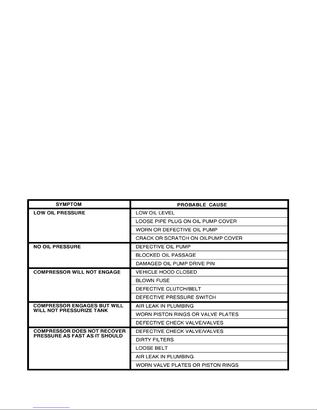
5-6. TROUBLESHOOTING
7. Move the compressor switch in the cab to the on
position to activate the clutch. Tighten the center
bolt in the pulley.
8. Test the unit for proper operation.
FIGURE E-5. TROUBLESHOOTING CHART
Page 19
DA425EA:99900679: 5-5
Page 20

DA425EA:99900679: 5-6
LIMITED W ARRANTY
WARRANTY COVERAGE - Products manufactured by Iowa
Mold Tooling Co., Inc. (IMT) are warranted to be free from
defects in material and workmanship, under proper use,
application and maintenance in accordance with IMTs written
recommendations, instructions and specifications as follows:
1. Ninety (90) days; labor on IMT workmanship from the date
of shipment to the end user.
2. One (1) year; original IMT parts from the date of shipment
to the end user.
IMTs obligation under this warranty is limited to, and the sole
remedy for any such defect shall be the repair or replacement (at
IMTs option) of unaltered parts returned to IMT, freight
prepaid, and proven to have such defect, provided such defect
occurs within the above stated warranty period and is reported
within fourteen (14) days of its occurence.
IMPLIED WARRANTY EXCLUDED - This is the only
authorized IMT warranty and is in lieu of all other express or
implied warranties or representations, including any implied
warranties of merchantability or fitness for any particular
purpose or of any other obligations on the part of IMT.
ITEMS EXCLUDED - The manufacturer gives no warranty on
any components purchased by the manufacturer, and such
components as are covered only by the warranties of their
respective manufacturers.
WARRANTY CLAIMS - Warranty claims must be submitted
and shall be processed in accordance with IMTs established
warranty claim procedure.
WARRANTY SERVICE - Warranty service will be performed
by any IMT distributor authorized to sell new IMT products of
the type involved or by any IMT Service Center authorized to
service the type of product involved or by IMT in the event of
direct sales made by IMT. At the time of requesting warranty
service, the purchaser must present evidence of the date of
delivery of the product. The purchaser shall pay any premium
for overtime labor requested by the purchaser, any charge for
making service calls and for transporting the equipment to the
place where warranty work is performed.
WARRANTY VOIDED - All obligations of IMT under this
warranty shall be terminated:(1) if service other than normal
maintenance or normal replacement of service items is performed
by someone other than an authorized IMT dealer, (2) if product
is modified or altered in ways not approved by IMT.
PURCHASERS RESPONSIBILITY - This warranty covers
only defective material and workmanship. It does not cover
depreciation or damage caused by normal wear, accident,
improper protection in storage, or improper use. The purchaser
has the obligation of performing the care and maintenance duties
discussed in IMTs written recommendations, instructions and
specifications. Any damage which results because of purchasers
failure to perform such duties shall not be covered by this
warranty. The cost of normal maintenance and normal
replacement of service items such as filters, belts, etc. shall be
paid by the purchaser.
CONSEQUENTIAL DAMAGES - The only remedies the
purchaser has in connection with the breach or performance of
any warranty on IMT products are those set forth above. In no
event will the dealer, IMT or any company affiliated with IMT,
be liable for business interruptions, loss of sales and/or profits,
rental or substitute equipment, costs of delay or for any other
special, indirect, incidental or consequential losses, costs or
damages.
REPRESENTATIONS EXCLUDED - IMT products are subject
to no expressed, implied or statutory warranty other than herein
set forth, and no agent, representative or distributor of the
manufacturer has any authority to alter the terms of this
warranty in any way whatsoever or to make any representations
or promises, express or implied, as to the quality or performance
of IMT products other than those set forth above.
CHANGE IN DESIGN - IMT reserves the right to make
changes in design or improvements upon its products without
imposing any obligation upon itself to install the same upon its
products theretofore manufactured.
Effective January, 1985
This parts manual is provided to the user to assist in servicing the equipment. It is the propertyof Iowa Mold Tooling Co., Inc and, as
such, may not be reproduced either whole or in part,whether by chemical, electrostatic, mechanical or photographic means without the
expressedwritten permission of an officer of Iowa Mold Tooling Co., Inc. One manual is provided with each piece of new equipment and
additional manuals may be obtained at a nominal price.
IOWA MOLD TOOLING CO., INC.
BOX 189, GARNER, IA 50438-0189
TEL: 515-923-3711
TECHNICAL SUPPORT FAX: 515-923-2424
 Loading...