

Page 1
Description
1. Liner Phase Shifter technology
permits the antenna to achieve
high performance, high power rating low vswr, and broader band
coverage on both 2m and 70cm
bands.
2. Direct element joint structure with
two interconnected FRP outershells. Enables the antenna to
maintain the same strength as one
with one piece structure. The ring
gasket makes the antenna waterproof, and therefore maintains
performance even in rainy weather.
When required, the antenna can be
easily assembled or disassembled
by adjusting the joint bracket
accordingly.
3. Professional quality maximum
wind resistance is achieved by the
rugged structure. Superior waterproofing eliminates unstable
VSWR that might otherwise
happen in climatic weather. This
antenna may also be used in seaside
or contaminated air environments
as it is rust and corrosion free.
4. Both of the bands, 2m and 70cm,
can be operated simultaneously by
using optional antenna duplexer.
5. DC ground structure, which
escapes high voltage caused by
lightning, protects your radio and
equipment.
Specifications
FREQUENCY: 144-148 MHz
435-450 MHz
GAIN: 6.0 dB
8.0 dB
POWER: 200 Watts
IMPEDANCE: 50 Ohms
VSWR: less than 1.5:1
MAX WIND
RESISTANCE: 50m/sec (112 MPH)
MAST DIAMETER
ACCEPTED: 30-62mm
(1-1/5” to 2-2/5”)
LENGTH: 2.5m (98.4”)
WEIGHT: 1.2 kg (2.6 lbs.)
CONNECTOR: UHF Female
WARRANTY: 1 Year against
defects in material
or workmanship.
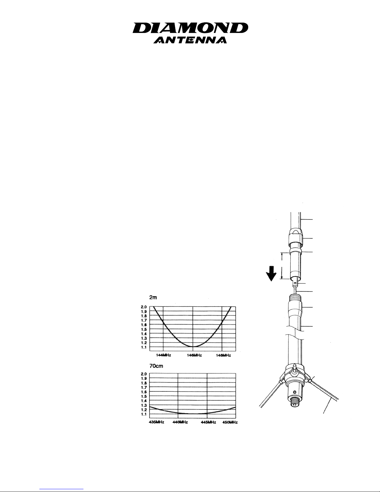
VSWR Charts
Adjustment
All X-Series antennas are completely
adjustment free. If VSWR of an antenna is extraordinarily high, see if each
connecting part is well contacted. It is
most likely due to bad contact in the
coaxial cable and/or connector connection, or soldering problem. Be sure to
use 50ohm coaxial cable to feed the
antenna.
Assembly
Continued on next page...
X200A
2m/70cm Dual Band High Performance Gain Base Station Antenna
DIAMOND ANTENNA Products are distributed by RF PARTS COMPANY
435 S. Pacific Street • San Marcos, CA 92078 • (760) 744-0900
www.diamondantenna.net
Upper Outershell
Upper Outershell
Joint Bracket
Gasket Holder
Element Joint Bracket
Lower Element
Lower Outershell
Joint Bracket
Lower Outershell
Radial Element
Lock Nut
Radial Element
10cm
Page 2
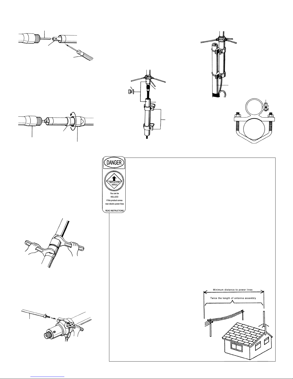
1. Connect upper and lower elements.
2. Put lower element into element
joint bracket thoroughly and fix it.
3. Then fix upper and lower outershells with outershell joint bracket
as shown in Fig. C.
4. Fasten upper outershell joint
bracket with a wrench by holding
lower outershell joint bracket
firmly with a wrench at the same
time. Fasten the brackets until there
is no gap between them to ensure a
waterproof connection.
5. Attach three radial elements as
shown in Fig. E.
6. Attach two mast brackets to the
support pipe. Then connect a coaxial
cable to the feedpoint section through
the support pipe. By aligning the holes
at the bottom of the feedpoint section
and upper part of the pipe, fasten the
pipe with a lock screw.
7. Attach assembled antenna on mast,
taking balance into account.
Fig. D
Fig. E
Fig. F
Fig. G
Radial Element
Lock Nut
Radial
Element
Fig. C
Fig. B
Gasket Holder
Lower Outershell Joint Bracket
Upper Outershell Joint Bracket
Lock Washer
Align holes
and fasten.
Feedpoint
section
Support Pipe
Mast
Brackets
Lower Element
Element Joint Bracket
Screw Driver
For Your Safety
Please read the following safety
precautions before antenna assembly.
• Assemble the antenna on the ground or
wide and flat place such as on balcony
before installation.
• Do not assemble or install the antenna on a
place where you can not have enough distance from any electric power lines.
• Do not install the antenna on a rainy or
windy day.
• Do not attempt to install the antenna only by yourself.
Installing the antenna alone on the roof may lead you to
a dangerous accident. Always ask your friends or a
professional for help installing the antenna.
• Do not use iron or aluminum ladder at a reachable
distance from any electric power lines.
• Do not install the antenna on a mast which is not
grounded properly.
• Do not have your family members or friends touch or
come close to the antenna, unless they have realized its
potential danger.
TO AVOID FATAL ACCIDENT
• Do not attempt to sustain the antenna, or any part of
support structure if it begins to fall down. Let it fall by itself.
• Do not attempt to remove or restore the antenna or any
part of support structure if it touches an electric power
line. Let it be as it is, do not touch it, and call your local
electric power company immediately.
IN CASE OF AN ACCIDENT
• Do not touch a person or an animal who is or seems to
be in contact with the antenna or any support structure
which is fallen on a live electric power line. Touching
one may lead you to be electrocuted.
• Do not attempt to separate a person or an animal who is
or seems to be in contact with the antenna or any support
structure which is fallen on a live electric power line by
yourself. Call or have someone call a police officer,
ambulance, or doctor immediately.
Antenna Installation Precautions
To determine antenna installation location, there are
several factors to be taken into account. First thing is
antenna propagation direction to specific target stations.
As to whether there are any obstacles such as tall
buildings on the line of sight. Next is specific installation
location. As to whether specific location is adequate in
terms of antenna support and surrounding safety.
• Do not attempt to install the antenna by yourself if you
do not have any experience in installing base station
antenna. Ask your experienced friends or a professional
for help.
• Do not attempt to install the antenna at a location where
it does not have enough distance from nearby electric
power lines. It is advised to install the antenna at least
twice of total antenna height from nearby electric
power lines.
• Do not install the antenna on any type of tower, pole or
telescopic mast which exceeds 30 feet high, if you do
not have enough experience in installing the antenna on
that kind of location. Ask your experienced friends or a
professional for help.
• Do not use more than 1/10’ section if you install the
antenna on iron plumber’s pipe. Attach guy wire if multiple pipes are used to install the antenna.
Lock
Screw
Antenna
Mast
Mast Bracket
Mast
 Loading...