

Page 1

Page 2

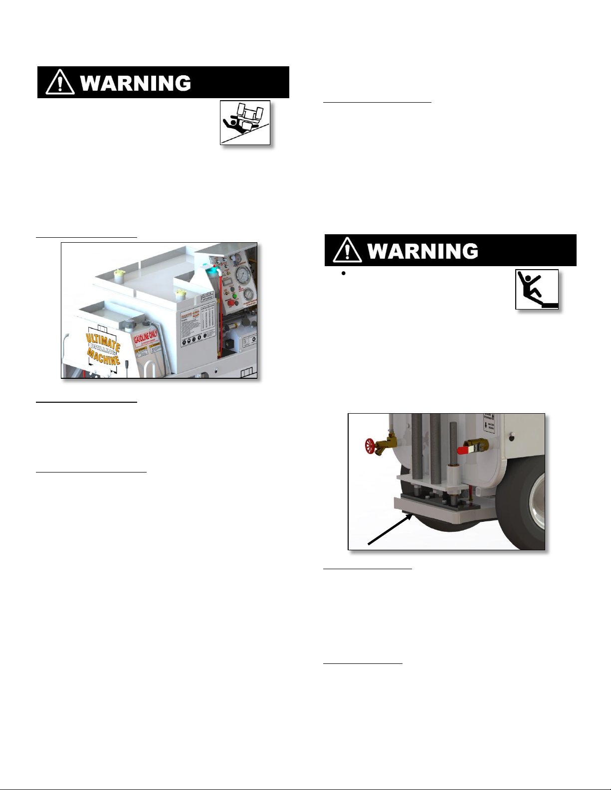
ULTIMATE DRILLING MACHINE
OPERATING SUMMARY
STARTING: The function switch at the rear
control panel must be in the center (Neutral)
position between DRIVE & DRILL, and the
MASTER DISCONNECT switch must be ON. Be
certain both red EMERGENCY STOP switches
are pulled out. The engine throttle, choke and
start key are all located at the rear of the
machine on the right side of the engine.
MOVING: The self propelled function only works
with the function switch in the DRIVE position.
Gently raise and lower the lever on the drive
valve mounted in the upper rear corner of the
machine. To steer the unit, lift the rear tires of
the ground and pivot to the proper location.
The machine may also be move manually by
lifting the rear tires off the ground and pushing
or pulling. Be certain the rear legs and front
mast are raised fully for maximum ground
clearance.
DOWN switch to slowly start the hole. Once
contact is made, switch to AUTO DRILL mode,
drilling will continue until the cylinder stroke is to
its maximum length or until the AUTO DRILL
switch is shut off.
The DRIIL DOWN, DRILL UP, and TURBO switches
will NOT operate when the AUTO DRILL mode is
on.
TWO SPEED DRILL MOTOR: Set to high speed for
drills up to 10” in diameter (Shift Clockwise) and
low speed for drills greater then 10” (Shift
Counter Clockwise).
IMPORTANT! A red emergency stop button is at
the rear and side controls panels. This will stop
the engine and shut down all hydraulic and
electrical systems. These buttons must be in the
out position to start the engine.
DRILLING: The labels at the front controls
summarize the typical drilling operation. Please
read them and review the following additional
information.
After positioning the drill, put the function
switch in the upper DRILL position. This activates
the controls on the front dash panel. Be certain
the circuit breakers at the rear electrical outlet
panel are on as AC power is required by the
vacuum pump.
The DRILL DOWN, DRILL UP, and TURBO switches
are intermittent and must be held in to
operate. Holding UP or DOWN and TURBO will
raise or lower the drill more rapidly for initial
positioning or pulling bit out of hole. To adjust
the speed of cylinder stroke, hold up or down
and turn the small black knob at the upper
right of the manifold control. This is also the
maximum speed the drill can move while in
AUTO DRILL mode and should be set low. With
the drill set to the proper RPM, gently jog
Page 3

Table of Contents
Safety P r ecautions
1
Safety Alerts
1
Proposition 65
1
Spark Arrester Requirements
1
Repertory Hazards
1
General Safety
2
Battery & Electrical Safety
2
Drill Safety
3
Fuel Safety
3
Engine Safety
3
Hydraulic Safety
4
Belt Safety
4
Transportation Safety
4
Lifting Safety
4
Introduction to The UDM
5
Components
5
Controls
6-7
Dimensions & Specifications
8
Operating The UDM
9
Light Tower
9
Lift Points
9
Fuel System
9
Battery
9
Engine
10
Drive Lever
10
Water System
11
Vacuum System
11-12
Drill Mode
12
Diamond Core Bits
13
Stuck Cores
15
Stuck Bits
16
Maintaining UDM
17
Maintenance Overview
17
Part Lubrication
17
Tires
17
Battery
18
Electrical System
18
Hydraulic System
19
Belt System
19
Engine
20
Storage
20
References
21
Appendix A Serial Tags
21
Appendix B Maintenance Chart
21
Appendix C Belt Tensioning
22
Appendix D Additional Resources
22
Appendix E Troubleshooting
23
Parts Manual
24
UDM Overview
24
Drive Train Assembly
25
Drive Axle Assembly
Alternator Assembly
Water & Vacuum Systems
Vacuum Pump Assembly
Electrical Outlet Box
Dash Panel Assembly
Rear Stabilizer Assembly
Vacuum Base Assembly
Drill Mast Assembly
Hydraulic System
Pillow Block Assembly
Decal Kit
Wiring Diagram
Maintenance Records
Warranty Information
27
28
29
31
32
34
36
37
38
40
43
44
45
46
47
Page 4

Safety Precautions
1
Operate the Ultimate Drilling Machine (UDM) and
all of its components according to this manual.
Failure to comply with and understand the following
safety, operations, and maintenance instructions
can result in serious injuries and/or death. All
operators must be properly trained or supervised by
experienced personnel prior to using the machine
and should understand the risks and hazards
involved. Improper or unintended machine usage is
discouraged and Diamond Products cannot be
held liable for damages.
Machine modifications should be made by
Diamond Products to ensure safety and design. Any
modifications made by the owner(s) are not the
responsibility of Diamond Products and void all
warranties if a problem arises as a result of the
modification.
Refer to the UDM Parts List for additional information
and part diagrams. Refer to the engine manual
and manufacturer as the primary source for all
safety, operations, and maintenance instructions
regarding the engine. Prior to operating, record the
machine’s serial number, and the engine’s model
and serial numbers in Appendix A.
Notice: The information in this manual may be
updated at any time!
Safety Alerts
Serious injuries and/or death will occur if these
instructions are not followed.
Serious injuries and/or death could occur if these
instructions are not followed.
Mild and/or moderate injuries could occur if these
instructions are not followed.
Proposition 65
Engine exhaust and some of its
constituents are known to the
State of California to cause
cancer, birth defects, and/or
other reproductive harm.
Spark Arrester Requirement
In the State of California
4442 or 4443 to use or operate the engine on any
forest-covered, brush-covered, or grass-covered
land unless the engine is equipped with a spark
arrester, as defined in Section 4442, maintained in
effective, working order or the engine is
constructed, equipped, and maintained for the
prevention of fire pursuant to Section 4443.
it is a violation of Section
Respiratory Hazards
Concrete drilling produces dust and fumes known
to cause illness, death, cancer, respiratory disease,
birth defects, and/or other reproductive harm.
Safety protection techniques include, but are not
limited to:
• Wearing gloves.
• Wearing safety goggles or a face shield.
• Using approved respirators.
• Washing work clothes daily.
• Using water when wet cutting to minimize
dust.
• Washing the hands and face prior to
eating/drinking.
For additional safety and self-protection
information, contact your employer, the
Occupational Safety and Health Administration
(OSHA), and/or The National Institute for
Occupational Safety and Health (NIOSH).
Page 5
General Safety
2
• Read and understand all safety, operations,
and maintenance instructions provided in this
manual prior to operating or servicing the
machine.
• Keep the machine clean and free of slurry,
concrete dust, and debris.
• Inspect water hoses prior to operating the
machine. Clean, repair, or replace damaged
components.
• Repair the machine immediately if a problem
arises.
• Replace machine decals if unreadable.
• Dispose of all hazardous waste materials
according to city, state, and federal
regulations.
• Always have a phone nearby, and locate the
nearest fire extinguisher and first aid kit prior to
operating the machine.
• Persons under the statutory age limit should not
operate the machine.
• Operate the machine wearing flame resistant
clothing.
• Always let the machine cool after operating to
prevent serious burns.
• Replace all guards and access panels prior to
operating the machine.
• DO NOT operate the machine around
combustible materials or fumes to prevent
fires/explosions.
• Fit blocks/jacks under the frame edges at the
front and back of the frame for support when
working under the machine.
• All non-routine maintenance tasks should be
performed by an authorized service center.
DO NOT:
• Drop equipment, supplies, tools, etc., when
handling to prevent injuries.
• Lift and carry equipment, supplies, tools, etc.,
that are too heavy.
• Operate the machine without using the
appropriate safety equipment required for the
work task.
• Operate or service the machine with clothing,
hair, or accessories that can snag in the
machinery.
• Operate the machine using attachments not
associated with or recommended for the
machine.
• Operate the machine with anyone near the
work area.
• Operate the machine until unnecessary
materials have been removed from the work
area.
• Operate the machine with loose nuts, screws,
and bolts.
• Operate the machine when ill or fatigued.
Battery and Electrical Safety
• Ignitable explosive gases are
emitted from the battery. DO NOT
expose the battery to sparks or
open flames.
• Keep the area around the battery well-
ventilated.
• Keep the battery level when handling it.
• Use protective eyewear or a face shield and
avoid contact with the skin when
handling/servicing the battery.
• Use a proper battery tester when testing the
battery strength.
• Always connect the battery cables to the
proper terminal to ensure safety.
• Regularly inspect the battery, cables, clamps,
and terminals for damages. Clean, replace,
tighten, and grease components as necessary.
• Always keep the battery cable clamps away
from the battery terminals when the battery is
disconnected to avoid accidental connections.
• Immediately rinse your clothing, skin, or eyes
with water if exposed to battery acid. Seek
medical attention immediately!
• Turn off the master battery disconnect when
servicing the machine.
• Disconnect the battery prior to servicing the
machine unless stated otherwise.
• Remove the battery when storing the machine
for longer periods.
• Disconnect external equipment connected
through the electrical outlets prior to servicing
the machine.
• Do not plug external equipment into the
electrical outlets that requires more power than
the outlets are rated for.
• Always use the correct size fuses (amps) to
prevent fires.
• Disconnect the battery prior to servicing the
electrical system unless stated otherwise.
• DO NOT use the electrical outlets for equipment
that requires more power than the outlets are
rated for.
Page 6
Drill Safety
Inspect all core bits prior to usage and discard
damaged bits. Remove debris from bits and
clean as necessary.
Keep all body parts away from rotating core
bits.
Always use an appropriate size bit for the drilling
task. The bit must fit tightly on the spindle shaft.
Wear gloves and be alert to the surrounding
environment when handling core bits.
Always use the correct bit type for the material
being drilled.
Always start the engine with the function switch
at Start/Drive.
DO NOT exceed the core bit’s maximum
recommended speed when drilling.
DO NOT use damaged core bits when drilling to
avoid harming yourself, others, or the machine.
DO NOT activate the spindle shaft when
installing a core bit by hand to avoid
entanglement.
Failure to properly secure the core bit to the
spindle shaft may cause the bit to loosen or fall
off the machine.
Raise the core bit/pillow block assembly to a
sufficient height when maneuvering the
machine to provide proper clearance between
the bit/spindle shaft and the ground.
Remove all body parts from under the core bit
when releasing the bit from the spindle shaft.
DO NOT stand on the machine to act as an
anchor. Use the vacuum pump to anchor the
machine.
Always make sure the mast is firmly touching the
ground prior to drilling.
The work area should not contain buried or
embedded electrical, gas, or water lines.
Turn off all electricity, gas, and water lines
around the work area prior to drilling.
Use extreme caution when drilling through
floors. Another trained worker must clear the
surrounding area on the lower floor prior to
drilling in case the core falls to the lower floor.
DO NOT allow any person, animal, or object in
and around the work area when drilling.
Excessive drilling speeds at first
contact with the concrete surface
can cause bit breakage, resulting
in serious injuries and/or death.
Use extreme caution when operating the
machine on slopes, as it is more susceptible to
sideways tipping/rolling over, especially with a
full water tank.
When driving the machine forward or
backward, be alert to the surrounding
environment.
When parking the machine on a slope, lower
the rear legs and front mast or chock the tires to
prevent rolling.
Fuel Safety
Store all fuel in appropriate safety containers.
DO NOT operate the machine with a fuel leak.
DO NOT fuel the machine with the engine
running.
Let the engine cool prior to adding fuel.
Refer to the engine manual for recommended
fuels.
DO NOT smoke or expose fuel to
open flames when filling the fuel
tank or working with fuel.
Clean up spilled fuel prior to starting the engine.
Move the machine away from the fueling area
prior to starting the engine.
Drain the fuel tank and fuel lines for longer
storage periods. Refer to the engine manual for
additional information.
Engine Safety
Refer to the engine manual as the primary
source for engine safety.
Always know how to turn off the engine for
emergency purposes.
Fill the fuel tank and check the oil level prior to
starting the engine.
DO NOT leave the engine running unattended.
Keep all body parts away from
rotating machine parts with the
engine running.
DO NOT start the engine without the air filter(s)
installed.
DO NOT allow dust to enter the air intake tube
when cleaning/replacing air filter(s).
Immediately replace damaged machine
components that may allow dust to enter the
engine.
Always operate the machine in
well-ventilated areas.
Concentrated engine exhaust can
cause loss of consciousness and/or
death.
Wipe down the engine’s exterior and oil cooler
daily/regularly to prevent high operating
temperatures. DO NOT spray the engine with
water to prevent engine damage.
DO NOT touch the engine/muffler assembly with
the engine running, and always let the parts
cool down prior to touching them or servicing
the machine.
Handle hot oil carefully when changing the oil.
Page 7

Hydraulic Safety
4
• Turn off the engine prior to servicing the
hydraulic system.
• Turn off the engine prior to disconnecting
hydraulic hoses.
• Pay attention to the hydraulic oil thermometer.
The maximum recommended oil temperature is
180°F.
• Remove the core bit to reduce residual pressure
in the cylinder circuit prior to servicing the
machine.
• DO NOT use external hydraulic equipment that
requires a higher flow rate than what the
machine is rated for.
• Always use a piece of cardboard or
paper to check for hydraulic fluid
leaks. Keep all body parts away
from leaks and/or areas that may
eject hydraulic fluid. Pressurized hydraulic fluid
can penetrate the skin, causing serious injuries.
Seek medical attention immediately!
• Refer to the Department of Transportation (DOT)
for additional information on proper
transportation techniques and truck/trailer
requirements.
Lifting Safety
• Move yourself and all others
away from the lifting area when
hoisting the machine to prevent
being crushed underneath.
• Secure the appropriate hoisting cables, straps,
and/or chains to the machine’s designated lift
points on the frame prior to hoisting it.
• DO NOT attempt to lift the machine irresponsibly
and/or improperly.
Belt Safety
• Turn off the engine prior to servicing the belts.
• Let the belts cool down prior to servicing them.
• Regularly inspect the belts for fraying, stress
cracks, and/or breakage and replace
immediately when damaged.
• Over-tensioning the belts may damage the
engine crankshaft. Under-tensioning the belts
may cause slippage, shorter belt life, and poor
alternator performance.
• Make sure the belts are aligned prior to
operating the machine.
Transporting Safety
• Close the fuel shutoff valve when transporting
the machine.
• Drain the fuel tank when transporting the
machine long distances.
• Use heavy-duty ramps that will support the
weight of the machine and yourself when
loading or unloading.
• The towing truck/trailer should be in good
working condition.
• Use extreme caution when guiding the machine
up and down ramps. Slowly drive the machine
forward down the ramp, or slowly back the
machine in reverse up the ramp. Avoid standing
directly downhill from the machine to avoid
serious injuries.
• Turn off the engine once the machine is loaded
into the truck/trailer.
• Chock the wheels and secure the machine in
the truck/trailer prior to transporting.
Page 8
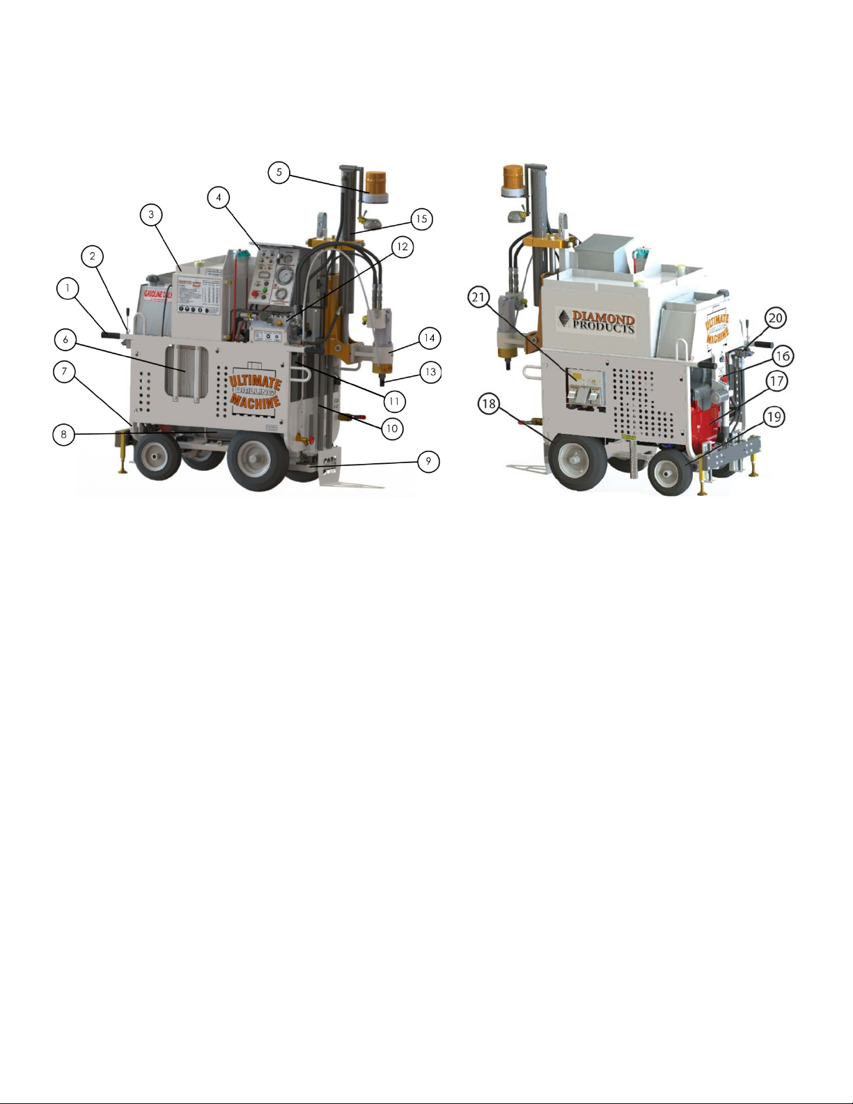
Introducing the UDM
1. Handlebar
5
Components
The UDM is a self-contained, self-propelled drilling machine with electric and hydraulic power outlets.
2. Handlebar Lock Pin/Knob
3. Water Tank
4. Front Control Panel
5. Light Tower
6. Heat Exchanger
7. Frame
8. Alternator
9. Vacuum Base
10. Mast
11. Hydraulic Oil Tank
12. Main Hydraulic Manifold
13. Spindle Shaft
14. Pillow Block
15. Hydraulic Cylinder
16. Rear Control Panel and DC
Fuses
17. Engine
18. Front Tires
19. Rear Tires
20. Drive Lever
21. Electrical Outlets and Circuit
Breakers
Page 9
Controls
1. Strobe Light – Powers strobe light.
12. Vacuum Valve – Holds or releases vacuum.
6
Side Control Panel
2. Power Indicator - Indicates power supply to
machine.
3. Vacuum Switch – Turns vacuum pump ON/OFF.
4. Rear Stabilizer Switch – Raises and lowers rear
stabilizer.
5. Vacuum Lift Switch – Raises and lowers vacuum
base.
6. Digital Readout – Indicates Bit RPM.
7. Auto Drill Switch – Locks the drill down function
until cylinder reaches maximum length, or until
switch is turned off. Drill Down, Drill Up, and Turbo
buttons do not work when Auto Drill switch is
activated.
8. Drill Up Push Button – Raises Core Bit.
9. Emergency Stop – Stops engine and all systems of
machine.
10. Drill Down Pushbutton – Lowers core bit.
11. Pressure Switch Adju ster –Adjust pressure to core
bit.
13. Vacuum Gauge – Indicates vacuum pressure.
14. 3000 PSI Pressure Gauge – Indicates drive motor,
drill motor, or hydraulic outlet pressure.
15. Pressure Indicator- Indicates too much pressure is
being applied to core bit.
16. Turbo Button – Raises or lowers core bit at
maximum speed. Turbo button must be pressed
while holding Drill Down or Drill Up to indicate
direction. Turbo button does not work when Auto
Drill switch is activated
17. 500 PSI Pressure Gauge- Indicates cylinder
pressure when drilling.
18. Drill RPM Adjustment – Increases or decreases core
bit rpm.
19. Cylinder Speed Adjuster – Increases or dec reas es
core bit’s maximum raise and lower speed.
20. Work Light – Powers work light on mast.
21. Water Pump Switch – Turns water pump ON/OFF.
Page 10
Controls
7
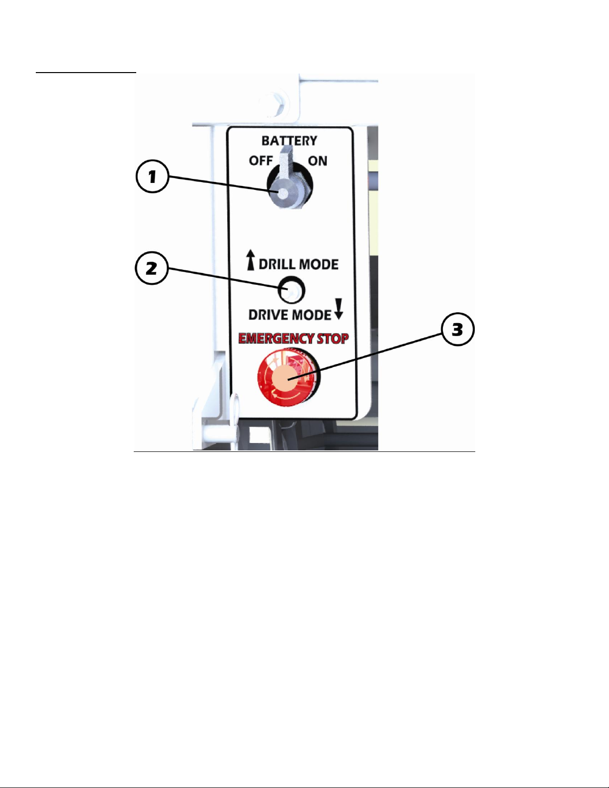
Rear Dash Controls
1. Mastery Battery Disconnect – Connects or disconnects battery circuit. NOTE: Always
disconnect when finished operating machine.
2. Function Switch – Three position switch. Up position is Drill mode, center is Start/Neutral Mode,
and down position is Drive Mode.
3. Emergency Stop Button – Stops engine and all systems of machine.
Page 11
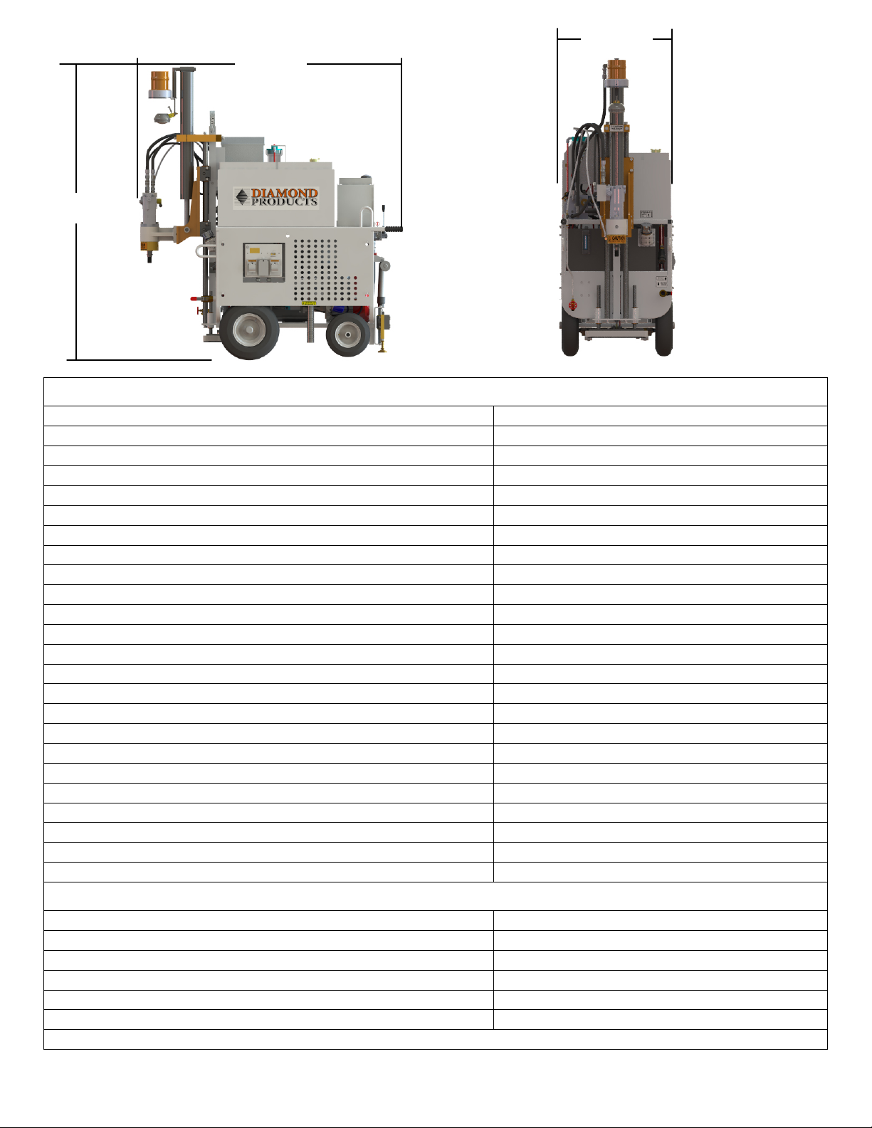
Ultimate Drilling Machine Specifications
Overall Height
81.75”
Overall Width
31.00”
Overall Length
73.25”
Overall Length W/ Handlebars Extended
99.25”
Weight (Add 450lbs. For Fuel, Hydraulic Fluid, and Water)
1100 lbs.
Core But Diameter
4.00”-24.00”Ø
Spindle Shaft Thread
1.25”-7.00”
Belt Drive
Single Belt
Core Bit Coolant
Water
Handle Bars
Single Position, Variable Lengths
Drive Speed
3.25 MPH Maximum
Electrical Power
5000 Watts
Electrical Outlets
115V and 230V single phase twist lock, 115V GFI.
Hydraulic Power Supply
2000 PSI Maximum
Hydraulic Power Flow Control
14 GPM
Hydraulic Quick Disconnects
½”
Fuel Capacity
9.00 Gallons
Water Tank Capacity
44 Gallons
Hydraulic Tank Capacity
12 Gallons
Engine Tachometer / Hour Meter
Standard
Core But RPM Tachometer
Standard
Work light
Standard
Strobe Light
Standard
Hole Locator
Standard
Engine Specifications
Manufacturer
Honda
Model
GX660
Fuel Type
Unleaded Gasoline
Air Filter
Dual Element
Low Oil Alert
Standard
Electric Start
Standards
NOTE: Refer to engine manual for additional engine specifications and info.
73.25”
81.75”
31.00”
8
Page 12
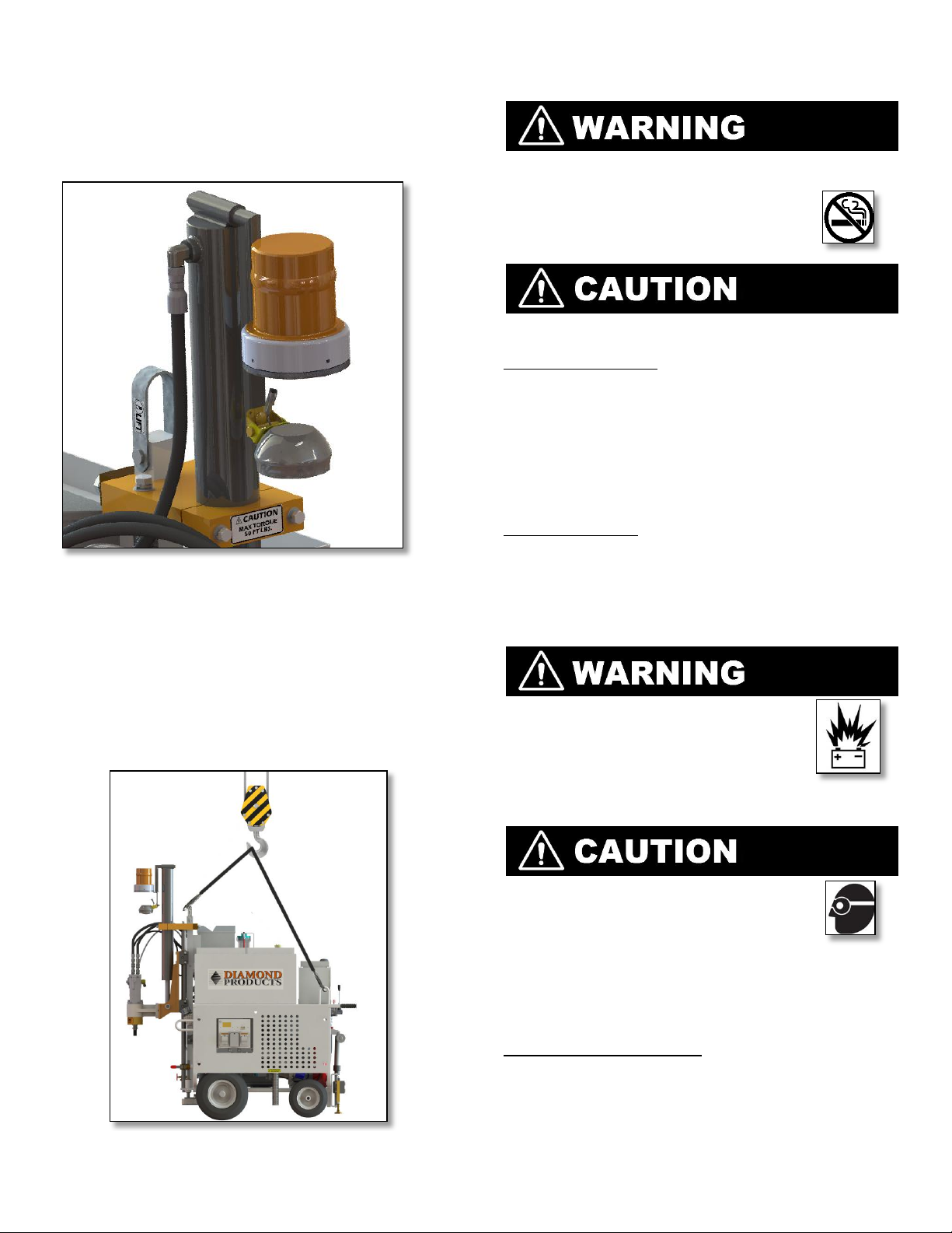
Light Tower
9
Use the strobe light to alert others when operating
the machine. Use the spotlight for additional
lighting as necessary.
Fuel System
DO NOT operate the machine with a fuel leak.
DO NOT fuel the machine with the engine running.
DO NOT smoke or expose fuel to open
flames when filling the fuel tank or
working with fuel.
Clean up spilled fuel prior to starting the engine.
Fueling the Machine
1. Turn off the engine and let the machine cool
down.
2. Remove the fuel tank cap.
3. Fill the fuel tank with unleaded gasoline as
necessary. Refer to the engine manual for fuel
ratings and additional refueling information.
4. Replace the fuel tank cap.
Lift Points
There are two welded loops, one on each side of the
frame at the rear of the machine, and there is one
shackle near the top of the frame column at the front of
the machine. Secure the lifting cables, straps, and/or
chains to these three points and adjust them so the
overall lift point is near the front axle. Note: The empty
center of gravity is just behind the front axle. This
location will shift toward the rear slightly with a full water
tank.
Fuel Shutoff Valve
5. Open the shutoff valve to open the fuel lines.
6. Close the shutoff valve to close the fuel lines.
Battery
Ignitable explosive gases are emitted
from the battery. DO NOT expose the
battery to sparks or open flames, and
keep the area around the battery wellventilated.
Use a proper battery tester when testing
the battery strength.
Use protective eyewear or a face shield
and avoid any contact with the skin
when handling/servicing the battery
The machine contains a charged battery with one
positive cable lead and one negative cable lead.
Master Battery Disconnect
The master battery disconnect connects or
disconnects the battery’s circuit. Note: The master
battery disconnect must be on prior to starting the
engine.
Page 13
10
1. Turn on the master battery disconnect to
connect the circuit (the indicator light directly
below will light up when activated). Note: The
strobe light, spotlight, water pump, and rear
and front raise/lower cylinders will operate with
the engine off and master battery disconnect
on. Be careful not to drain the battery when
using these items with the engine off and
battery connected.
2. Turn off the master battery disconnect to
disconnect the circuit.
Engine
Stopping the Engine
• DO NOT leave the machine unattended
until the engine is off and the core bit has
stopped spinning.
1. Turn off all switches/controls.
2. Move the function switch to Start/Drive.
3. Decrease the throttle to Min.
4. Turn the ignition key to Off and remove the key.
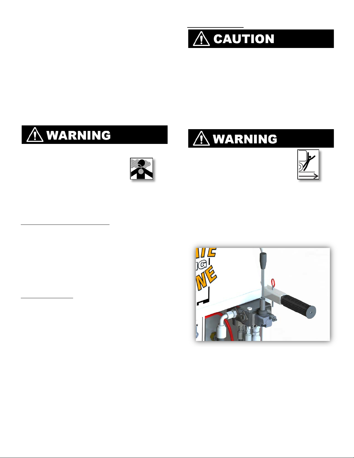
Drive Lever
• DO NOT leave the engine running unattended.
Operate the machine in wellventilated areas. Concentrated
engine exhaust can cause loss of
consciousness and/or death.
Refer to the engine manual as the primary source
for information regarding the engine.
Tasks Prior to Starting the Engine
Complete the tasks listed below prior to starting the
engine to ensure a proper start.
• Check fluids and fill to appropriate levels.
• Turn off controls and switches.
• Pull out emergency stop buttons.
• Set engine throttle to Min.
• Remove tools from work area.
• Raise core bit off ground.
Starting the Engine
1. Open the fuel shutoff valve.
2. Move the function switch to Start/Drive. Close
the choke on the engine (not required on warm
engine).
3. Turn on the master battery disconnect.
4. Increase the throttle by 1/3.
5. Insert the ignition key, turn to Start, and release
when the engine starts. If the engine doesn’t
start, release the key and try again after 10
seconds. Note: Refer to the engine manual if
the engine doesn’t start after several attempts.
6. Gradually open the choke as the engine warms
up.
7. Increase the throttle on the engine to Max.
When driving the machine forward
or backward, be alert to the
surrounding environment to avoid
harming yourself, others, or the
machine.
The drive lever moves the machine at variable speeds based on its position. The maximum driving speed with the engine running is ~3.25 mph. Use the handlebars to lift the rear tires off the ground and pivot, push, or pull the machine manually.
1. Move the function switch to Start/Drive.
2. Push the drive lever down to move the machine
forward. Release the lever to stop.
3. Pull the drive lever up to move the machine in
reverse. Release the lever to stop.
Page 14
Water System
11
Use extreme caution when
operating the machine on slopes,
as it is more susceptible to sideways
tipping/rolling over, especially with
a full water tank.
The water system cools the core bit and flushes
slurry from the drilling hole. Note: Always test the
water supply for adequate pressure and flow prior
to drilling.
Filling the Water Tank
Filling the Water Tank
1. Remove the water tank cap(s) and fill the tank
with water as necessary. Note: The clear hose at
the rear of the tank indicates the water level.
2. Replace the cap(s) when finished.
NOTE: Too much water makes the slurry look clear
and waste water, insufficient water makes slurry
thick and can result in a core sticking in bit.
Draining Water System
1. Be certain the area is safe for draining
water.
2. Open large valve located on the front right
side of machine.
3. Complete draining is only required in areas
where temperatures result in freezing, or
machine is going to be stored for a long
period of time.
Vacuum System
DO NOT stand on the
machine to act as an
anchor. Use the vacuum
pump to anchor the
machine.
The vacuum system is only used during the drilling
operation when the base is firmly on the ground;
this adds stability to the system and should be used
whenever possible. Cleaning and wetting the
surface with the garden hose helps to ensure a
proper seal.
Using the Water Supply
1. Open the water valve directly under the water
tank. DO NOT confuse this valve with the water
release valve, which is located near the side of
the tank.
2. Turn on the Water switch.
3. Open the water valve.
4. Adjust the water flow valve to increase or
decrease water flow to the core bit. Note: Using
too much water when drilling will make the slurry
look clear. Not using enough water will make
the slurry look thick and pasty, and could result
in a stuck bit.
5. Use the attached water hose for cleaning or
other tasks as needed. This hose functions as a
typical garden hose. Note: Turn on the master
battery disconnect to use the water hose with
the engine off. DO NOT drain the battery.
6. Decrease the water flow and close the water
valve when finished.
7. Turn off the Water switch. Note: Always turn off
this switch when finished drilling to avoid
draining the battery.
Using the Vacuum
1. Turn on the circuit breakers.
2. Close the vacuum valve on side dash.
3. Turn on the Vacuum switch.
4. Open the vacuum valve to release suction
when finished.
5. Turn off the Vacuum switch.
Vacuum Gauge
The vacuum gauge indicates that the vacuum
system is working. Vacuum pressure should max out
at 25” Hg. Note: Poor vacuum suction may indicate
loose hose fittings; loose water trap jars; worn
vacuum base seals; or the base may be placed
over a cracked/scored surface where suction is not
possible.
Page 15
Water Jars
12
The primary jar is mounted on the water tank
next to the side dash unit and helps keep
water and other contaminates from being
sucked into the pump. The secondary jar is
located adjacent to the vacuum pump
behind the form right wheel of the machine.
Visually inspect and empty the containment jar
on a regular basis. The jars unscrews by hand.
Failure to empty this jar will result in vacuum
pump damage.
Primary Water Jar
Secondary Water Jar
Drill Mode
Introduction and Initial Settings: The following
items can only be used or adjusted with the
function switch in DRILL mode. The
recommended pressure settings are maximum
limits. They will typically only be reached
intermittently if rebar or hard spots are
encountered when drilling.
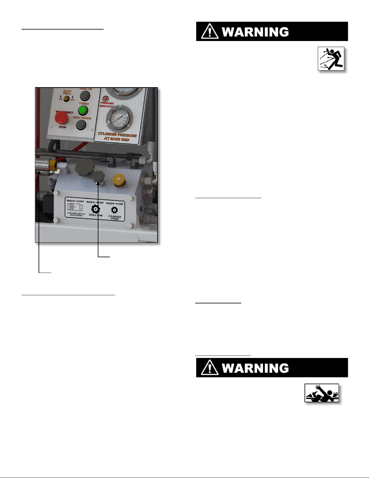
Cylinder Pressure
The cylinder pressure controls how hard the bit
pushes downward. The pressure is factory set
at 200 psi and should rarely need adjustments.
Monitor the cylinder pressure using the 500 psi
gauge on the main hydraulic manifold and
adjust to the factory setting as necessary.
1. Start the engine.
2. Move the function switch to Drill.
3. Turn off the Drill Rpm cartridge.
4. If no bit is attached to the machine, press the
Drill Down button to fully extend the cylinder. If
a bit is attached to the machine, place a sturdy
block of wood under the bit and press the Drill
Down button to push the bit against the piece
of wood (as if trying to lift the front end of the
machine).
5. Holding the Drill Down button, adjust the
Cylinder Pressure Base End valve on the main
hydraulic manifold to adjust the cylinder
pressure. DO NOT exceed 200 psi when drilling
without the vacuum. Note: Use caution and
good judgment when increasing the pressure
above 200 psi, which will increase the risk of
jammed bits.
6. Press the Drill Up button to raise the cylinder for
proper ground clearance.
Cylinder Speed
While holding the drill DOWN switch, turn the
small black knob at the top right of the main
hydraulic manifold. This sets the maximum
speed the drill can move (unless in TURBO
mode) and should be set to the slow end of
the adjustment, Slow speed is particularly
important at initial drill to ground contact. This
setting should rarely need adjustment.
Page 16
Drill Motor Pressure Switch
Cylinder Speed
Adjustable
13
An adjustable pressure switch monitors the drill
motor pressure and will automatically shift the
cylinder to neutral (stops pushing) if it senses
the drill motor pressure rises above 1500 psi
(hard spots). The cylinder will then
automatically cycle ON/OFF as the drill works
through rebar or other hard spots.
• DO NOT exceed the core bit’s
maximum recommended
speed when drilling. Excessive
drilling speeds at first contact
with the concrete surface can
cause bit breakage, resulting in serious
injuries and/or death.
• DO NOT use damaged core bits when
drilling to avoid harming yourself, others, or
the machine.
Diamond Core Bits
Using the proper core bit (size and type)
preserves the bit and improves drilling and
operator efficiency, resulting in lower costs.
Refer to www.diamondproducts.com for
additional drilling and core bit information.
Inspecting the Core Bit
Inspect each core bit prior to installation and
discard all damaged bits. Inspect all core bits
for:
Raising and Lowering the Drill
The DRILL DOWN, DRILL UP, and TURBO switches
are intermittent switches and must be held to
operate. Holding UP or DOWN and TURBO will
raise and lower the drill more rapidly for initial
positioning and quickly pulling a bit out of a
hole. These switches will not work when the
AUTO DRILL mode is selected.
Raising and Lowering Frame and Mast
To establish a more solid base, the pneumatic
tires are raised off the ground. This same action
places the vacuum base firmly on the ground.
Electric cylinders at the front and rear of the
machine are controlled by intermittent
switches located on the main side control
panel. The frame should be raised until the
front tires are just clear of the ground.
Independently adjusting the front and rear
controls allows slight leveling of the machine.
Pressure Switch
Adjuster
• Cracks, nicks, and dents on barrel
• Darkness and/or discoloration near
edge of bit
• Uneven wear
• Missing segments
• Bent segments
• Segment cracks
Core Bit Speeds
Refer to the chart on the machine for the
recommended core bit speeds when drilling.
DO NOT exceed the maximum recommended
drilling speed.
Installing a Core Bit
• Be extremely careful when
installing a core bit by hand
with the spindle shaft
activated to avoid
entanglement.
• Failure to properly secure the core bit to the
spindle shaft may cause the bit to loosen or fall
off the machine.
Page 17

• Wear gloves and be alert to
14
the surrounding environment
when handling core bits.
1. Select the correct core bit size and type for the
drilling task.
2. Raise the spindle shaft to provide room to
install the core bit.
3. For smaller core bits: Holding the bit with both
hands, screw the hub onto the spindle shaft
until it bottoms out on the shaft. Make sure the
bit is secure (the bit will tighten further once it
enters the concrete).
4. For larger core bits:
a) Place the bit under the spindle shaft and
align the bit and hub with the shaft threads.
b) Start the engine.
c) Set the Drill Rpm cartridge to the slowest
rotating speed.
d) Set the Cylinder Speed knob to a very slow
speed.
e) Press the Drill Down button to slowly lower
the spindle shaft until the threads are
engaged with the hub. CAUTION: Proper
hub and spindle shaft alignment is critical to
avoid cross threading when installing the
core bit. Stop immediately and readjust the
bit if the shaft and hub are not aligned when
installing the bit. When aligned, the shaft will
screw itself into the hub and lift the bit off
the ground. If required, apply light
resistance to the bit to prevent spinning,
which will allow the shaft to screw itself
completely into the bit.
f) Turn off the Drill Rpm cartridge.
5. Raise the core bit to provide clearance
between the bit and the ground.
Removing a Core Bit
Move all body parts away from
the core bit when releasing the bit
from the spindle shaft.
1. Lower the core bit to be very close to the
ground.
2. Grasp the flats near the top of the spindle using
the wrench provided. Hold the wrench in
place to stabilize the spindle shaft and use
another appropriate tool to grasp the core bit
hub.
3. Turn the tool clockwise to loosen the core bit.
Remove smaller bits by hand when the bit is
near the end of the threads. Continue
removing larger bits using the tool; the bit will
release and fall to the ground. Note: Keeping
the bit close to the ground or dropping it onto
stable pieces of wood will help prevent
segment damage when the bit releases.
4. When the bit is near the end of the threads,
a. Remove smaller bits by hand,
b. Allow larger buts to release and fall
to the ground. Keep bit close to the
ground to minimize impact and help
prevent segment damages.
Dropping the bit onto would or other
soft surfaces will reduce impact.
• Excessive drilling speeds or lowering to quickly of
bit at first contact with the
concrete surface can cause bit
breakage, resulting in serious
injuries and/or death.
• Turn off all electricity, gas, and
water around the work area prior to drilling.
• Use extreme caution when
drilling through floors. Another
trained worker must clear the
surrounding area on the lower
floor prior to drilling in case the
core falls to the lower floor.
Helpful Hints Prior to Drilling
Keep the following in mind for better efficiency
while drilling:
• Avoid drilling excessively deep to preserve the
core bit and reduce costs.
• For proper vacuum suction, make sure the
drilling surface is clean and solid (no cracks,
dents, etc.). Wetting the surface can help when
vacuum sealing.
• Use a proper water flow to prevent damaged
and stuck bits. Using too much water when
drilling will make the slurry look clear. Not using
enough water will make the slurry look thick and
pasty.
Tasks Prior to Drilling
Complete the following tasks prior to drilling:
• Raise the core bit to provide clearance
between the bit and the ground when
maneuvering the machine.
• Clearly mark the drilling area.
• Be sure the work area does not contain any
buried or embedded electrical, gas, or water
lines.
Page 18

Drilling a Hole
15
Reminder: Always refer to the Drill Mode section in
Operating the U to set the cylinder pressure and drill
motor pressure prior to drilling.
1. Position the machine and core bit.
2. Move the function switch to Drill.
3. Lower the front mast and rear legs. All tires
should just clear the ground and the front and
rear tire height should match up so the machine
is level.
4. Turn on the Vacuum switch and close the
vacuum valve. Check the vacuum gauge for
pressure; stop to determine the problem when
suction fails. Skip this step if the vacuum cannot
be used when drilling.
5. If the machine is equipped with a 2-speed drill
motor, set the motor to High for bits up to 10”
and Lo for bits larger than 10”.
6. Adjust the Drill Rpm cartridge based on the bit
size. Refer to the core drilling speeds chart on
the machine for the recommended core bit
speeds when drilling. DO NOT exceed the
maximum recommended drilling speed.
7. Turn on the Water switch.
8. Turn on the water valve and adjust the water
flow valve to increase or decrease the water
flow. Note: Always have a proper water
pressure and flow when drilling for maximum
core bit efficiency. DO NOT continue drilling
when a problem arises with the water system.
9. Push the Drill Down button and SLOWLY lower
the bit to start the hole. Once ground contact is
made continue drilling to the desired depth, or
release the Drill Down button and turn the Auto
Drill switch to On/Drill (the bit will lower until the
cylinder fully extends or until Auto Drill is turned
off) to drill to the desired depth. DO NOT use
Auto Drill until after the bit has contacted the
surface to prevent serious injuries or damage to
the machine.
10. Release the Drill Down button or turn off the
Auto Drill switch.
11. Press the Drill Up button to raise the bit out of the
hole. Note: Pressing the Turbo and Drill Up
buttons together will raise the bit quickly.
12. Turn off the Drill Rpm cartridge.
13. Decrease the water flow and turn off the water
valve and Water switch.
14. If used, turn off the Vacuum switch and open
the vacuum valve to release suction.
15. Lower all tires to the ground. Note: Make sure
the mast and rear legs are fully lifted for
maximum ground clearance.
16. Move the function switch to Start/Drive.
Continuing a Partial-Hole
1. Inspect the drill hole and remove, if possible,
items that may cause the bit to stick (lost core
bit segments, broken concrete).
2. Align the bit with the previous hole and slowly
lower the bit back into the hole. DO NOT drill
unless the core bit is aligned with the hole.
3. Finish drilling the hole following the directions
directly above.
Stuck Cores
Removing a Stuck Core
4. Remove the core bit from the machine.
5. Move the bit away from the work area.
6. Lay the bit on the ground. DO NOT hammer on
the core bit to avoid denting the tube, which
can result in additional problems and increased
hang-ups.
7. Option 1:
a) Place a metal spike through the hub and
drive the core out of the bit.
b) Inspect the bit for damages and clean or
replace as necessary.
8. Option 2:
a) Thread a piece of threaded rod (1-1/4-7)
through the hub until it contacts the
concrete.
b) Place two hex nuts on the rod end and lock
them against each other.
c) Holding the bit in place, grasp both nuts
using a wrench and turn to push the rod
against the concrete, which will drive the
core out of the bit.
d) Inspect the bit for damages and clean or
replace as necessary.
DO NOT hammer or pry on the bit! This will dent the
tube, which can result in additional prob lems and
increase hang-ups.
Stuck Bits
Stuck core bits happen most frequently in the
following circumstances:
• An insufficient water supply allows slurry to
accumulate, causing the drill to seize.
• Pushing the drill down too hard can cause
the machine’s frame to shift slightly (more
susceptible when not using the vacuum).
• Drilling completely through a slab may
cause segments to catch at the bottom
edge of the hole when raising the bit.
• Partially cutting through a piece of rebar
with just the outer edge of the bit (mooning)
can deflect the bit, causing it to jam. Slowly
cutting through rebar or hard spots may help.
Page 19

Removing a Stuck Bit
3. Turn off the Drill Rpm cartridge.
16
1. Release the Drill Down button or turn off the Auto
Drill switch. Press the Drill Up or Drill Down button
and Turbo button together to raise and lower the
bit to try and free it. Note: If the bit is not spinning,
turn the Drill Rpm cartridge on and off to try and
get the bit to spin (this will cause the drill motor
pressure to max out). If the bit is spinning, try to
keep it spinning while attempting to raise the bit.
Continue with step 2 if this attempt fails.
2. If the bit has moved toward the rear of the hole,
lower the rear legs slightly to attempt to realign the
bit. If the bit has moved toward the front of the
hole, raise the rear legs slightly to attempt to
realign the bit. Use the Drill Up and Drill Down
button while slightly raising and lowering the rear
legs or front mast in an attempt to find the breakfree position. Continue with step 3 if this attempt
fails.
4. Move the function switch to Start/Drive.
5. Turn off the engine.
6. Grasp the flats near the top of the spindle using
the wrench provided and turn counterclockwise
to disconnect the spindle shaft from the bit.
7. Move the machine away from the bit. Note: It may
be necessary to start the machine, lower the tires,
and raise the cylinder for proper ground
clearance.
8. Thread a piece of threaded rod (1-1/4-7) through
the hub until it contacts the concrete.
9. Place two hex nuts on the rod end and lock them
against each other.
10. Grasp both nuts using a wrench and turn to push
the rod against the concrete, which will pull the bit
out of the concrete.
NOTE: Inspect the bit for damages and clean or
replace as necessary.
Page 20

Maintaining the UDM
17
Part Lubrication
Failure to read and comply with the maintenance
instructions provided in this manual prior to
performing maintenance may result in serious
injuries and/or death, and may harm the machine.
DO NOT attempt to perform maintenance on the
machine if you are not properly trained for it, or are
not supervised by an experienced person.
Refer to the Diamond Products’ Parts List for
additional information and part diagrams when
performing maintenance tasks. Refer to the engine
manual and manufacturer as the primary source for
all safety, operations, and maintenance instructions
for the engine. All non-routine maintenance tasks
should be performed by an authorized service
center. Contact the machine and/or engine
manufacturers with any additional questions.
Maintenance Overview
Complete the following tasks as required. DO NOT
delay maintenance! Print the Error! Reference
source not found. from Error! Reference source not
found. to keep track of maintenance tasks
completed.
Daily/Regularly
Inspect belts for tension and wear. Replace or
re-tension as necessary.
Inspect machine for damages.
Tighten loose nuts, screws, and bolts.
Check all fluid levels and fill as necessary (fuel,
water, hydraulic oil, engine oil).
Wipe down and clean machine to remove dust,
debris, and slurry from components (especially
fans).
Wipe down engine’s exterior and oil cooler.
Look for fluid leaks.
Check hydraulic oil filter gauge and replace
filter as necessary.
Check water trap jars and clean as necessary.
Check tire pressure and add air as necessary.
Clean air cleaner (see engine manual).
Inspect hydraulic hoses, couplings, and fittings
for leaks.
Clean quick disconnects prior to connecting
hydraulic hoses.
Inspect the roller carriage and adjust as
necessary.
Note: Refer to the engine manual and
manufacturer for daily engine care and
maintenance tasks.
DO NOT grease parts with
the engine running.
Lubricating parts on schedule increases the
machine’s efficiency and life. Use NLGI No. 2
premium lithium-based grease when lubricating
parts.
Hydraulic Pillow Block
Lubricate the pillow block grease fitting every 40
hours of operation.
Rear Axle
Lubricate both rear axle bearing grease fittings
annually.
Tires
Fit blocks/jacks under the
frame edges at the front and
back of the frame for support
when working under the
machine.
Inspect the tires regularly for damages and wear
and replace as necessary. Fill the tires with air
(check tire sidewall for recommended tire pressure)
as necessary.
Replacing the Front Tires
1. Raise the front tires slightly off the ground.
2. Remove the dust cap.
3. Loosen the setscrew in the set collar.
4. Remove the set collar and tire from the front tire
shaft.
5. Place a new tire onto the shaft.
6. Place the set collar against the tire on the shaft.
7. Tighten the setscrew into the set collar to secure
the tire.
8. Replace the dust cap.
Replacing the Rear Tires
1. Raise the rear tires slightly off the ground.
2. Loosen the setscrew in the set collar.
3. Remove the set collar and tire from the rear
axle shaft.
4. Place a new tire onto the shaft.
5. Place the set collar against the tire on the shaft.
6. Tighten the setscrew into the set collar to secure
the tire.
Page 21

Battery
18
• Ignitable explosive gases are
emitted from the battery. DO NOT
expose the battery to sparks or
open flames, and keep the area
around the battery well-ventilated.
• Always keep the battery cable
clamps away from the battery
terminals when the battery is
disconnected to avoid accidental
connections.
Disconnect the battery prior to servicing the
machine unless stated otherwise.
• Use a proper battery tester when
testing the battery strength.
• Use protective eyewear or a face
shield, and avoid contact with the
skin when servicing the battery.
Battery Type
12 Volt, Group U1
battery to a recycling facility; many battery
retailers also accept old batteries.
7. When cleaning the battery, inspect the
terminals, clamps, and cables for damages and
corrosion. Clean the terminals and clamps using
a wire brush, or use another approved
technique for cleaning. Use acid-free, acidresistant grease to grease the battery clamps
and terminals.
8. Reconnect the positive cable lead to the
positive battery terminal and replace the
battery boot. Note: Always reconnect the
positive cable first.
9. Reconnect the negative cable lead to the
negative battery terminal and replace the
battery boot.
10. Fit the battery support brace over the battery
and secure the brace using the screw/nut
assembly.
11. Turn on the master battery disconnect as
needed.
Electrical System
• Disconnect the battery when
servicing the electrical system
unless stated otherwise.
• Always use the correct size
fuses (amps) to prevent fires.
• Disconnect external equipment connected
through the electrical outlets prior to servicing
the machine.
Refer to the UDM Parts List for electrical diagrams.
Servicing the Battery
1. Turn off the master battery disconnect.
2. Remove the battery support brace screw/nut
assembly and battery support brace.
3. Remove the negative battery boot and
disconnect the negative cable lead from the
negative terminal. Note: Always disconnect the
negative cable first.
4. Remove the positive battery boot and
disconnect the positive cable lead from the
positive terminal.
5. Carefully remove the battery from the frame.
6. When replacing the battery, carefully place a
new battery onto the frame. Bring the old
Fuse Panel
Inspect fuses (inside dash panel) if switches or
controls are not working properly and replace as
necessary. If the fuses fail frequently, determine the
cause and repair immediately.
ircuit Breakers
C
Reset the circuit breakers as necessary. If the circuit
breakers trip or fail frequently, determine the cause
and repair immediately.
Page 22

Hydraulic System
19
• Always use a piece of
cardboard or paper to check
for hydraulic fluid leaks. Keep all
body parts away from leaks
and/or areas that may eject hydraulic fluid.
Pressurized hydraulic fluid can penetrate the
skin, causing serious injuries. Seek medical
attention immediately!
• Remove the core bit to reduce residual pressure
in the cylinder circuit prior to servicing the
machine.
Inspect the hydraulic hoses and fittings daily for
leaks. Replace damaged components
immediately.
Changing the Hydraulic Oil
An oil analysis program is recommended to
determine the oil’s condition and when to change
it. Along with the program; if the oil is kept clean,
dry, and has been operated at moderate
temperatures it may last for several years. With no
analysis program, change the oil every 200 hours.
1. Place an oil drain tray under the hydraulic
tank’s drain plug.
2. Remove the drain plug and drain the oil from
the tank. Replace the plug when completely
drained. Dispose of the used oil according to
city, state, and federal regulations.
3. Fill the tank to just below where the filler port
extends from the hydraulic tank. DO NOT overfill
as oil expands when hot. DO NOT contaminate
the oil to avoid damaging system components.
Use a high quality, petroleum based hydraulic
oil with the following properties:
a) Anti-wear
b) Low foaming
c) Rust and oxidation inhibitors
d) Wide temperature range
e) Fluid viscosity: 8-1,000 Centistokes (Cs)/(52-
4,600 SUS). Note: The machine is shipped
with an ISO 46 viscosity grade (8 Cs/52 SUS @
212°F/100°C and 46 Cs/210 SUS @
104°F/40°C).
4. Replace the oil cap and secure.
Changing the Hydraulic Oil Filter
Check the hydraulic filter gauge daily and replace
the filter once the gauge needle enters the red
range.
1. Place an oil drain tray under the hydraulic filter.
2. Unscrew the filter and hold it over the tray to
catch falling oil. Dispose of the used filter and oil
according to city, state, and federal
regulations.
3. Lightly oil the new filter’s rubber gasket with
clean oil.
4. Tighten the new filter according to the
directions on the filter.
5. Inspect the seal for leaks.
Belt System
• Turn off the engine prior to
servicing the belts.
• Always let the belts cool down prior to servicing
them.
Inspect the belts daily for fraying, stress cracks,
and/or breakage and replace immediately when
damaged. DO NOT exceed the manufacturer’s
belt tension settings when tensioning belts. Note:
Over-tensioning the belts may damage the engine
crankshaft. Under-tensioning the belts may cause
slippage, shorter belt life, and poor alternator
performance.
Tensioning the Engine Belt
1. Test the belt tension. Refer to Appendix C for
additional information and belt tension settings.
If adjustments are necessary, continue.
2. Loosen the nut on the four screws (under the
frame) securing the alternator to the frame.
Page 23

3. Turn the belt adjustment shaft nut clockwise
20
to tighten the belt. Retest the tension and
readjust the nut as necessary to reach the
required tension setting. DO NOT exceed
the manufacturer’s setting.
4. Retighten the four nuts (under the frame) to
secure the alternator.
Replacing the Engine Belt
1. Loosen the nut on the four screws (under the
frame) securing the alternator to the frame.
2. Loosen the belt adjustment shaft nut. DO NOT
remove the nut.
3. Slide the alternator toward the engine to loosen
the belt.
4. Remove the belt from the alternator sheave.
5. Remove the two screws securing the hydraulic
pump to the pump mount. Holding the
hydraulic pump, move the pump over to
remove the coupling assembly from the pump
mount. Note: There is no need to remove any
hoses from the hydraulic pump.
6. Remove three of the four screws securing the
pump mount to the engine, the fourth must be
loosened.
7. Move the pump mount away from the engine
to provide access to the engine sheave.
8. With the pump mount loose, guide belt around
sheave, pull belt out through pump end.
9. Insert loop of new belt through rear opening
and out the side of pump toward generator.
Guide belt around coupler and into position on
the engine sheave.
10. Secure the pump mount to the engine.
11. Holding the hydraulic pump, place the coupling
assembly into the pump mount and fit the end
of the coupling assembly onto the engine
crankshaft.
12. Secure the hydraulic pump to the pump mount.
13. Retighten the coupling assembly setscrew to
secure the coupling assembly to the engine
crankshaft.
14. Loop and align the belt around the alternator
sheave.
15. Slide the alternator toward the side of the
machine (this will tension the belt slightly).
16. Turn the belt adjustment shaft nut clockwise to
tighten the belt. Test the tension and readjust
the nut as necessary to reach the required
tension setting. DO NOT exceed the
manufacturer’s setting.
17. Retighten the four nuts (under the frame) to
secure the alternator.
Engine
• Let the engine cool down prior
to servicing the machine.
• DO NOT service the machine
with the engine running unless
stated otherwise.
Refer to the engine manual and manufacturer for a
full maintenance schedule and additional
maintenance information.
Engine Throttle Screw
The engine throttle screw (located at the top of the
engine) is factory set at 3,550 rpm. The screw
regulates the maximum no-load engine rpm.
Occasionally check the setting on the rear control
panel tachometer and adjust the screw as
necessary.
• Turn off the engine.
• Adjust the throttle screw.
• Remove all tools from the area and restart
the engine. Check the engine rpm on the
rear control panel tachometer while at full
throttle.
• Turn off the engine and readjust the throttle
screw as necessary.
Cleaning the Engine
• Wipe down the engine’s exterior and oil
cooler daily/regularly to prevent high
operating temperatures. DO NOT spray the
engine with water to prevent engine
damage.
Storing
Complete the tasks listed below prior to storing the
machine for longer time frames:
• Drain the water lines/hoses.
• Drain all fluids.
• Turn off all switches and controls (including
the master battery disconnects).
• Clean and wipe down the machine to
remove dust, debris, and slurry from
components (especially fans).
• Remove the battery and store in a proper
location, out of reach from children.
• Store the machine in a dry area, protected
from outdoor elements, and out of reach
from children.
Page 24

Appendix A
Serial Number
Model Number
Serial Number
Table 1: Daily Maintenance Task Chart
Date
1.
Inspect belts for tension and wear.
Replace or re-tension as necessary.
2.
Inspect machine for damages.
3.
Tighten loose nuts, screws, and bolts.
4.
Check all fluid levels and fill as
necessary (fuel, water, hydraulic oil,
engine oil).
5.
Wipe down and clean machine to
remove dust, debris, and slurry from
components.
6.
Wipe down engine’s exterior and oil
cooler.
7.
Look for fluid leaks.
8.
Check hydraulic oil filter gauge and
replace filter as necessary.
9.
Check water trap jars and clean as
necessary.
10.
Check tire pressure and add air as
necessary.
11.
Check air cleaner (see engine manual).
12.
Inspect hydraulic hoses, couplings, and
fittings for leaks.
13.
Clean quick disconnects prior to
connecting hydraulic hoses.
14.
Inspect roller carriage and adjust as
necessary.
15.
Refer to engine manual and manufacturer for daily engine care and maintenance tasks.
21
Serial Tags
Record the machine’s serial number below for future reference and customer service purposes.
Record the engine’s model and serial numbers below for future reference and customer service purposes.
Appendix B
Daily Maintenance Task Chart
Page 25

Appendix C
Deflection (in.) should be equal to number of inches listed in chart
22
Belt Tension Setting
Model Engine Type Deflection Deflection Force
Table 1: Belt Tension Setting
Ultimate Drilling
Machine (UDM)
Appendix D
20.5HP Honda GX670
to 5000 W Alternator
above when deflection force (lb.) listed in chart above is applied to
middle of belt using tension gauge.
.10” 69 lb
Additional Resources
1. Diamond Products (www.diamondproducts.com)
• Ultimate Drilling Machine Parts List; Ohio, 2009
A Guide for Professional Concrete Cutters
Training Manual–Introduction to Diamond Blades, Bits, and Equipment
Diamond Products’ Equipment Catalog
Diamond Products’ Website (
2. Honda Motor Company (
Owner’s Manual; GX610, GX620, GX670; Japan, 2007
3. Concrete Sawing and Drilling Association (CSDA) (
The CSDA has many helpful concrete cutting publications available to members and non-members.
4. Association of Equipment Manufacturers (AEM) (
The AEM has a variety of safety and technical manuals available for various types of equipment, along with
a list of industry-standardized safety symbols.
5. Occupational Safety and Health Administration (OSHA) (
OSHA provides information on work-related safety and health practices.
6. The National Institute for Occupational Safety and Health (NIOSH) (
NIOSH provides information on work-related safety and health practices.
www.diamondproducts.com)
www.honda-engines.com)
www.csda.org)
www.aem.org)
www.osha.gov)
www.cdc.gov/NIOSH)
Page 26

Appendix E
Engine off?
Start engine.
Function switch in Drill mode?
Move function switch to Drill.
Engine off?
Start engine.
Engine off?
Start engine.
Circuit breaker off? Blown fuse?
mode?
Master battery disconnect off?
Turn on master battery disconnect.
4. Hydraulic outlets do not
work.
Function switch in Hydraulic
Outlets mode?
Move function switch to Hydraulic
Outlets.
Activate circuit breakers; check
reset button on ground fault outlet.
Vacuum valve open?
Close vacuum valve.
suction may not be possible.
Tighten fittings and water jars;
replace bad hoses.
Turn on 40 amp circuit breaker;
outlet.
Loose belt causing slippage?
Check belt tension.
alignment.
replace as necessary.
Overheating of belt?
Check belt tension.
8. Engine does not start.
information.)
Emergency stop button down?
Pull up emergency stop button.
Master battery disconnect off?
Turn on master battery disconnect.
23
Troubleshooting
Symptom Problem Solution
1. Core bit will not raise/lower.
2. Machine will not move
forward/backward.
Table 1: Troubleshooting
Function switch in Drill mode? Move function switch to Start/Drive.
3. Controls/buttons/switches
do not work.
5. Electrical outlets do not
work.
6. No vacuum suction.
7. Short belt life.
Function switch out of Drill
Circuit breaker off?
Broken engine belt? Replace engine belt.
Surface cracked/scored?
Vacuum line leak?
Circuit breaker off?
Broken engine belt? Replace engine belt.
Sheaves misaligned?
Worn sheave grooves?
Activate circuit breakers; replace
fuses; move function switch to Drill.
Check surface and readjust;
check reset button on ground fault
Use straightedge to check sheave
Check for groove wear and
(Refer to engine manual and
manufacturer for additional
engine troubleshooting
Fuel shutoff valve closed? Open fuel shutoff valve.
Page 27

ULTIMATE DRILLING MACHINE OVERVIEW
24
1 2
3
10
4
5 6
7
8
9
ITEM NUMBER
1 6079001
2 6079058
3 4645238
4 6079205
5 4645207
6 6079184
7 6079000
8 2400276
9 4645216
10
PART NUMBER
6079002
DESCRIPTION
Fuel Tank Weldment
Dash Assembly
Drill Mast Assembly
Rear Stabalizer Assembly
RIght Body Panel
Hole Guide
Hydraulic Tank Weldment
16.00" x 4.00" Foam Filled Tire
Left Body Panel
Water Tank Weldment
QUANTITY
1
1
1
1
1
1
1
2
1
1
Page 28

31
25
1 2 3 64 5
38
30
29
28
252627
UDM DRIVETRAIN ASSEMBLY
37
10 11 12 13 14 15
36
35
35
34
8
7
9
33
22
22
32
16
17
18
19
20
21 22 23
24
Page 29

ULTIMATE DRILLING MACHINE DRIVE TRAIN ASSEMBLY
ITEM NUMBER
PART NUMBER
DESCRIPTION
QUANTITY
1
4645109
Ultimate Drilling Machine Frame Weldment
1 2 4640108
20.5 HP Honda Engine W/Electric Start
1 3 4645159
Rear Axle Assembly
1 4 4645039
5KW Alternator Assembl y
1
5
6079178
Positive Battery Cable
1
6
2400276
16” x4” Tire W/Bearing & Cap
2 7 2900279
Lock Pin W/Lanyard
3 8 2500001
7/8” Handle Grip
3 9 4645199
36” Long Handle Bar
3
10
2500584
12 Volt Group Size U1 Battery
1
11
4646122
Battery Hold Down Bar
1
12
6079179
Negative Battery Cable
1
13
2600569
1.0 CI 2 Bolt SAE Hydraulic Pump
1
14
4645129
SAE 2 Bolt Pump Mount
1
15
4600158
Exhaust Pipe
1
16
2503909
1-3/4” Muffler Clamp
1
17
2702624
Honda Catalytic Muffler, R Side Exhaust
1
18
6091138
Exhaust Heat Shield
1
19
2500201
Gasoline Fuel Filter
1
20
6079181
Fuel Supply Line
1
21
2900013
3/8-16x1.25” Hex Cap Screw
2
22
2900473
3/8 Flat Washer
33
23
2900033
3/8 Hex Nut
2
24
6079001
Fuel Tank Weldment
1
25
6079182
Fuel Tank Rollover Hose
1
26
2505503
3/8”Hose Rollover Vent
1
27
2503294
Fuel Tank Cap W/Fuel Level Gauge
1
28
2804510
Battery Disconnect Switch
1
29
2800122
Toggle Switch ON/OFF/ON
1
30
2801367
Emergency Stop Switch
1
31
2701670
Rectifier Assembly
1
32
2900047
3/8-16x1.75” Hex Cap Screw
4
33
2900018
3/8-16 Nylon Lock Nut
4
34
2901405
¼-20 x 7½ Hex Cap Screw
2
35
2900126
¼ Flat Washer
4
36
2900024
¼ Split lock Washer
2
37
2900125
¼-20 Hex Nut
2
38
2400294
54 Tooth 20° 1.25” Bore Spur Gear
1
26
Page 30

4645159: AXLE ASSEMBLY
27
NOTE BEARING
ORIENTATION
6
5
9
3
5
4
8
7
6
3
3
5
1
2
4
5
ITEM NO.
1 4645114
2 2400298 Bearing, 1-1/4 x 1-1/2 x 1.0" 1
3 2400299
4 2500365
5 2500009 Set Collar, 1" ID 4
6 2400277
7 2900057
8 2900473
9 2900018
PART NUMBER
DESCRIPTION
Axle Shaft
Key, 1/4 x 1-3/4"
Pillow Block Bearing, 1-1/4"
Tire, 12 x 3-1/2, Foam Filled
3/8-16 x 3.75" Hex Head Cap Screw
3/8 FLAT WASHER
3/8-16 Nylon Lock Nut
QTY.
1
3
2
2
4
8
4
Page 31

4645039: ALTERNATOR ASSEMBLY, 5KW
28
5
4
ITEM
1 2800851 1
PART NO.
3
QTY.
1
7
8 7
4 PLACES
7 9
6
9
DESCRIPTION
Alternator, 5000 W., 115/230 V., 42/21 Amp
3 2501538 1 Square Key, 1/4 X 1-3/8"
4 2400283 1
5 2400281 1
6 4600100 1
7
8 2900013 4
9 2900018 5
2900047 9
Pulley, 3.11 OD x 1-1/2" Belt x1/2" Pitch
Cap Screw, Hex Hd., 3/8-16 x 1-1/4"
Bushing, QD, 1-1/8"
Belt Adjustment Assy.
3/8 Flat Washer
Lock Nut, 3/8-16 Nylon
Page 32

29
Page 33

ULTIMATE DRILLING MACHINE WATER & VACUUM SYSTEMS
ITEM NUMBER
PART NUMBER
DESCRIPTION
QUANTITY
1
6079002
UDM Water Tank
1 2 3200136
¼” Street Elbow
1 3 3200727
¼” NPT Breather
1 4 3205539
1/” MPT Bulkhead Coupler
1 5 3205892
¼” Male Branch Tee
1 6 3205767
Vacuum Gauge
1 7 3205891
Swivel Adapter
1 8 3201349
½” Hose Barb x ½” MPT Brass
2 9 6079170
Tank To Strainer Water Hose
1
10
3205904
½” x 4.00” Galvanized Nipple
1
11
3205766
Water Strainer
1
12
6079169
Water Feed Mount Bracket
1
13
2900196
3/8-16 x .750” Hex Cap Screw
1
14
2900006
3/8 Split Lock Washer
1
15
6079168
UDM Drill Head Water Supply Hose
1
16
3200390
#6 Hose Clamp
4
17
3205536
¼” MPT 3/8” Hose Barb Brass Fitting
1
18
3201330
½”MPT x ½” 90° Brass Hose Barb
2
19
3201525
1.00” Ball Valve
1
20
4646213
Water Tank Drain Hose
1
21
3201516
1.00” Galvanized Close Nipple
1
22
3205903
1.00” MPT x 1.00” Hose Barb 45°
1
23
6079171
UDM Strainer to Pump Water Hose
1
24
6079172
Water Jar to Vacuum Base Hose
1
25
2701694
½” Hose Barb x 90° Port Fitting
2
26
2600545
12V, 4 GPM Water Pump
1
27
2900126
¼” Flat Washer
12
28
2503269
#3 Hose Clamp
6
29
2900125
¼-20 Hex Nut
4
30
4645157
Vacuum Pump Assembly
1
31
3201366
½” MPT Faucet
1
32
3205537
½” x ¼” Brass Reducer Bushing
1
33
3205583
½”-14 NPFT Street Tee Fitting
1
34
6079173
Pump To Faucet Water Hose
1
35
6079174
Lower Faucet to Drill Head Hose
1
36
6079175
Vacuum Pump to Dash Hose
1
37
6079176
Vacuum Pump to Water Jar Hose
1
38
3201271
¼” NPT Water Valve
2
39
3205535
¼” MPT x 3/8” Brass Hose Barb
3
40
6079177
Water Level Sight Hose
1
41
3201383
3/8” MPT x 3/8” 90° Brass Hose Barb
2
42
2502851
2.00” NPT Fuel Tank Cap
2
30
Page 34

4
31
2
3
PUMP ASSEMBLY
VACUUM
4
6.4
6.5
6.6
6.1
6.2
6.3
5
1
TO VACUUM GAGE
AND VALVE AT
FRONT PANEL.
8
A
DETAIL A
SCALE 1 : 4
9
10
ITEM NO.
1 4645143 1
2 3200007 1
3 3200010 1
4 3200012 2
5 3200088 1
6 2700171 1
6.1 2700014 1
6.2 2700017 1
6.3
6.5 2700172 1
6.6 2700170 1
7 4641047 1
9 2900038 4
10 2900448 4
11
PART NUMBER
2700015
3200019
QTY.
1
1
DESCRIPTION
Vacuum Pump Assy., 115V, W/ Connectors
Close Nipple, 1/4 NPT
Pipe Tee, 1/4" FPT
Street Elbow, 1/4" NPT
Nipple, 1/4 MPT x 2-1/2", Sched. 40, Galv.
Water Jar Assembly
Water Jar Lid
Water Jar Gasket
Funnel Fitting
Float Ball
Water Trap Jar
Hose Assy., 1/4 x 33-3/8"
Lock Washer, #10 Split
Machine Screw, Hex Hd., #10-32 x 1/2"
Fitting, 1/4" NPSM Straight Pipe to 1/4" Hose Barb
Page 35

4645134 OUTLET BOX
32
1
10
11
8
8
39
10
9
11
16
38
15
16
19
37
7
3
54
12
7
7
6
13
18 18
17 17
14
Page 36

ULTIMATE DRILLING MACHINE ELECTRICAL OUTLET BOX
ITEM NUMBER
PART NUMBER
DESCRIPTION
QUANTITY
1
4645127
Electrical Box
1 3 4648047
Front Mount Bracket
1 4 2800858
20 AMP Circuit Breaker
1 5 2800859
40 AMP Circuit Breaker
1 7 2900017
#10-24 Lock Nut
4 8 2900009
¼” SAE Flat Washer
2 9 2900416
¼”-20 x ½” Hex Head Tap Screw 1
1
10
2900024
¼” Split Lock Washer
2
11
2900125
¼-20 Hex Nut
2
12
2800089
20A 250V Twist lock Receptacle
1
13
2800430
30A 125V Twist lock Receptacle
1
14
2800698
125V GFI Outlet
1
15
2800801
Outlet Cover
1
16
2800791
Outlet Cover
2
17
2800171
¾” Cord Connector
2
18
2801304
¾” Lock Nut
2
19
4645135
Cover Plate W/Seal
1
37
1800810
230V Voltage Label
1
38
1801348
115V Voltage Label
2
39
1800415
Diamond Product Label
1
33
Page 37

32
34
8
9
11
27
20
DASH PANEL ASSEMBLY
31 23 30 29 28 26
14
16
ITEM NO.
1 6079058
7 6091127
8 2800062
9 2800094
10
11
14
20
21
23
24
25
26
27
28
29
30
31
32
PART NUMBER
2800640
2800861
2800159
2808062
2808063
3201271
3205761
3205765
3205767
91773A194
3205539
3200136
3200727
2507038
2808081
7 1
10
DESCRIPTION
Control Panel Weldment
Faceplate, Control Panel
Toggle Switch On/Off
Switch, Toggle, Momentary
Indicator Light (Red)
Digital Indicator, LED
Toggle Switch, DPDT, On/On
Intermittent Push Button
Green Intermittent Push Button
Water Valve, 1/4"NPT
4.00" 0-3000 PSI Guage
2.00" 600 PSI Panel Mount Pressure Guage
Vacuum Guage
8-32 x.750" Pan Head Screw
1/4" NPT Bulkhead Coupler
1/4" Street Elbow
1/4" NPT Breather
LED Dash Light
Indicator Light (Blue)
252421
QTY.
1
1
4
2
2
1
1
2
1
1
1
1
1
12
1
1
1
1
1
Page 38

13
35
UDM INNER DASH CONTROL PANEL
A
A
21
14
20
17
16
18
15
SECTION
SCALE 1 : 3
19
A-A
ITEM NO.
13
14
15
16
17
18
19
20
21
PART NUMBER
2800872
2800144
2808037
2800635
2801328
2800291
2800512
2800560
91773A194
DESCRIPTION
Relay, 75 Amp, 12 V, SPST
Relay, 50 Amp, 12V, SPDT
12 Fuse BLock
Fuse, 5 Amp, Tan ATO, Blade Type)
Fuse, 30 Amp Green ATO/ATC
Fuse, 20 Amp Yellow ATO/ATC
Fuse, 15 Amp Blue ATO/ATC
Fuse, 25 Amp, Natural ATO, Blade Type)
8-32 x.750" Pan Head Screw
QTY.
1
2
1
5
1
1
1
1
8
Page 39

6
36
16
17
18
11
7
19
REAR STABALIZER ASSEMBLY
8
2
1
13
12
14
9
15
ITEM NO.
1 6079205
2 6091129
3 4645203
4 2900112
5 2400301
6 2400295
7 2900607
8 2900829
9 4646214
10
11
12
13
14
15
16
17
18
19
PART NUMBER
2900289
2902998
2900022
2900031
2900141
2900025
2900084
2900058
6079099
6079206
5
DESCRIPTION
REAR COUNTER WEIGHT
Tab, Rear Lift Plate
Leg
Hex Nut, 5/8-11
Leveling Pad, 5/8-11
Actuator, Electric, 12V, 5" Stroke
Clevis Pin, 1/2" x 2-3/4"
Hairpin Cotter, 1/8" x 5/8" to 7/8"
1.00" Guide Pin
5/16-18x2.25 HEX CAP SCREW
5/16-18x3 HEX HEAD CAP SCREW
5/16 FLAT WASHER
5/16 SPLIT LOCK WASHER
5/16-18 MEDIUM DUTY HEX NUT
1/2-13 x 1.25 HEX HEAD CAP SCREW
1/2 SPLIT LOCK WASHER
1/2 FLAT WASHER
REAR STABALIZER SLIDE BUSHING
REAR COUNTER WEIGHT
10
3
4
QTY.
1
2
2
2
2
1
2
2
2
8
4
12
12
12
4
4
4
2
1
Page 40

8
37
4
UDM VACUUM BASE ASSEMBLY
6
2
14
1
5
12
11
10
ITEM NO.
1 3100014
2 6091074
3 6091075
4 6011468
5 4643027
6 2400295
7 2900607
8 2900058
9 2900029
10
11
12
13
14
15
PART NUMBER
2901111
2900033
2903087
2900084
2900829
3200669
DESCRIPTION
Vaccuum Base Casting
Cylinder Mount Bar
Vacuum Base Mount Plate
1.00" Guide Pin
VACCUM BASE GASKET
Actuator, Electric, 12V, 5" Stroke
Clevis Pin, 1/2" x 2-3/4"
1/2 FLAT WASHER
3/8-16 x 1.50 HEX HEAD CAP SCREW
3/8 SPLIT LOCK WASHER
3/8-16 HEX NUT
1/2-13 x 1.75 HEX CAP SCREW
1/2 SPLIT LOCK WASHER
Hairpin Cotter, 1/8" x 5/8" to 7/8"
1/4 MPT x 1/4 HOSE BARB
9
15
7
3
13
QTY.
1
2
1
2
1
1
2
6
6
6
6
2
2
2
1
Page 41

14
15
16
17
18
37
19
20
21
22
38
23
24252627283031
12 13
36
11
6
7 8 9
35
8
33
34
10
39
29
5
4
3
2
1
UDM MAST ASSEMBLY
Page 42

ULTIMATE DRILLING MACHINE DRILLING MAST ASSEMBLY
ITEM NUMBER
PART NUMBER
DESCRIPTION
QUANTITY
1
4645109
Ultimate Drilling Machine Frame Weldment
1 2 2903140
¾”-10 x3.00”Hex Cap Screw
2
3
2900042
¾ Split Lock Washer
2
4
2900362
¾” x 2-3/4” Clevis Pin
1
5
6011472
Mast Clamp Block
1
6
2900829
1/8” Hair Cotter Pin
1
7
4900159
¾” Pin Shackle
1
8
2900062
1/8” NPT Grease Fitting
4 9 2900037
½”-13 Hex Nut
4
10
6011467
1.500ӯ Guide Bar
2
11
6091072
Top Mount Plate
1
12
2900693
½-13 x 3.00” Hex Cap Screw
4
13
3205754
3.00” x 16.00” Hydraulic Cylinder
1
14
2802597
Strobe Light
1
15
2802596
Strobe Light Base
1
16
6079096
Light Mounting Bracket
1
17
4645141
12V Spot Light Assembly
1
18
6011484
Pin Spacer
2
19
4645238
4.9/9.6 CI Hydraulic Motor
1
20
3205536
90° Brass ¼”MPT x 3/8” Hose Barb
1
21
4645215
1.250-7 Pillow Block Assembly
1
22
4641167
Drill Head Support Weldment
1
23
2500009
1.00” I.D. Set Collar
2
24
3201525
1.00” Ball Valve
1
25
3201516
1.00” Galvanized Close Nipple
1
26
3201366
½” MPT Faucet
1
27
3205537
½” MPT x ¼” FPT Reducer Bushing
1
28
3205583
½”-14 NPT Street Tee Fitting
1
29
2903114
5/8-11 x 3.00” Hex Cap Screw
4
30
2900113
5/8” Split Lock Washer
4
31
2900202
5/8” SAE Flat Washer
4
32
2900811
½-13 x 2.50” Hex Cap Screw
4
33
2900084
½ Split Lock Washer
10
34
6011483
Cylinder Pin
1
35
3200968
½” MPT x ½” MJIC Straight
1
36
2900837
½ SAE Flat Washer
2
37
2903094
½-133 x 4.50” Hex Cap Screw
2
38
6079168
3/8” Drill Head Water Supply Hose
1
39
6011470
Head Support Guide Block Assembly
2
39
Page 43

22
23
24
26
5
27
28
29
30
3135
71
A
11
10
DETAIL A
SCALE 1 : 16
68
69
16
15
13
14
12
17
32
21
25
3334
18
20
62
19
37 3638
39
70
7 8 9
6
5
UDM HYDRAULIC SYSTEM
4
3
66
2
1
64
65
41 404243
67
44
63
454647485051
49
61
60
59
58
57
56
55
54
53
52
Page 44

ULTIMATE DRILLING MACHINE H YDRAUL IC SY ST EM P A RT S LIST
ITEM NUMBER
PART NUMBER
DESCRIPTION
QUANTITY
1
3205754
3.00”x 16.00” Hydraulic Cylinder
1 2 3200726
½” MJIC x ½” MPT 90°
1
3
2507002
1-½” Brass Bushing
8
4
2900037
½” -13 Hex Nut
4 5 3200286
½” O-Ring x ½” MJIC Adapter
6
6
3205894
½” – FPT x ¼” MJIC Reducer
1
7
3205761
4.00” 0-3000PSI Panel Mount Pressure Gauge
1 8 2502924
½” MORB x ½” MJIC 90°
3 9 3205765
2.00” 600PSI Panel Mount Pressure Gauge
1
10
3205893
¼” FPT x ¼” MJIC Adapter
1
11
3205876
¼” FPT x ¼” FPT 90°
1
12
3200785
#6 O-Ring x ¼” MPT Straight
1
13
2402418
UDM Manifold
1
14
6079165
Manifold to 600psi Pressure Gauge Hose
1
15
3200967
¼” MPT x ¼” MJIC
1
16
3205657
#6 O-Ring x ¼” MJIC
1
17
2800641
¼” MPT Pressure Switch
1
18
3200739
#12 MORB x ¾” MJIC Adapter
1
19
6079152
Manifold To Cooler Hose
1
20
3200111
1.00” MPT x ¾” MJIC 90°
1
21
2400296
Air/Oil 12 Volt Heat Exchanger
1
22
3205895
6.00” Drive Valve Handle
1
23
3205864
Ground Drive Valve
1
24
3205657
#4 O-Ring x ¼” MJIC
3
25
2800697
½” NPT Temperature Switch
1
26
6079166
Manifold To Drive Valve Hydraulic Pressure Hose
1
27
6079167
Manifold to Drive Valve Return Hydraulic Hose
1
28
6079153
Cooler to Hydraulic Tank Filter Hose
1
29
6079158
Drive Valve to Drive Motor Pressure Hose
1
30
3200505
Hydraulic Filter Head
1
31
3205578
½” MJIC x ½” MJIC Straight Coupler
2
32
6079159
Drive Valve To Drive Motor Return Hose
1
33
3200626
#10 O-Ring x ¼” MJIC Adapter
2
34
2600561
Hydraulic Motor 19.7 CI
1
35
2400290
¾” x 1 1/8” Coupling Assembly
1
36
4645129
SAE 2 Bolt Pump Mount
1
37
3201175
Hydraulic Filter Element
1
38
2600569
1.0 CI 2 Bolt SAE Hydraulic Pump
1
39
2900238
7/16” Split Lock Washer
2
40
3200287
#10 O-Ring x ½” MJIC Straight Adapter
1
41
3200400
#12 O-Ring x ¾” MJIC 90°
3
42
3201261
¾” MJIC x ¾” MPT 90°
1
43
3201232
1 1/2” MPT x ¾” FPT Bushing
1
44
3200960
1.00” MPT x 1.00” MPT Straight
1
45
3205777
12.00” Hydraulic Tank Cap W/ Drain
1
46
6079000
Hydraulic Tank Assembly
1
47
2900811
½-13 x 2 ½ Hex Cap Screw
4
48
2900062
1/8” NPT Grease Fitting
4
49
6079163
Lower Cylinder to Manifold Hose
1
50
4641167
Drill Head Support Weldment
1
51
4645215
1 ¼”-7 Pillow Block Assembly
1
52
2500009
1.00” I.D Set Collar
2
53
6011484
Pin Spacer
2
41
Page 45

ULTIMATE DRILLING MACHINE HYDRAULIC SYSTEM PARTS LIST CONTINUED
54
6011483
Cylinder Head Pin
1
55
4645238
4.9/9.6 CI Hydraulic Motor
1
56
3200105
½” Quick Disconnect Nipple
2
57
3200104
½” Quick Disconnect Coupler
2
58
2900693
½-13 x 3.00 Hex Cap Screw
4
59
6079162
Drill To Tank Return Hydraulic Hose
1
60
6011470
Head Support Guide Block
2
61
2900084
½” Split Lock Washer
8
62
6079151
Tank to Pump Suction Hose
1
63
6079164
System Pressure Manifold To Gauge Hose
1
64
6079155
Drill To Manifold Return Hose
1
65
6079154
Drill To Manifold Pressure Hose
1
66
6079161
Manifold To Upper Cylinder Pressure Hose
1
67
6079160
Pump Pressure To Manifold Hose
1
68
3200709
Leveling Gauge
1
69
3200904
#6 O-Ring Plug
1
70
2900407
7/16-14 X 1.00” Hex Cap Screw
2
71
3200968
½” MPT x ½” MJIC Straight
1
42
Page 46

4645215: PILLOW BLOCK ASSEMBLY, 1-1/4-7 SPINDLE
43
9
6
7
8
7
13
ITEM
PART NO.
1 4644132 1
2 4641010 1
3 2900062 1
4 4699920 1
5 2700021 2
6 2400014 2
7 2400013 2
8 4699905 1
9 4699901 1
10 2900120 4 Cap Screw, Soc. Hd., 3/8-16 x 3"
11 2900047 4
12 2900006 4
13 2900124 4
QTY.
DESCRIPTION
Hydraulic Pillow Block
Key, 1/2" Sq. x 4" Long
Grease Fitting, 1/8" NPT
Water Housing
Trostel Seal
Bearing Race
Tapered Bearing
Spindle Shaft 1.250-7
Shim For Hydraulic Spindle Shaft
3/8 Flat Washer
Lock Washer, 3/8" Split
Cap Screw, Soc. Hd., 3/8-16 x 1-3/4"
1
6
11
3
12
2
4
10
5
Page 47

44
PART#1806008
ULITIMATE DRILLING MACHINE DECAL KIT
Page 48

45
Page 49

ULTIMATE DRILLING MACHINE
Date
Service Performed
Parts Used
46
Maintenance Records
Page 50

NOTES
____________________________________________________
____________________________________________________
____________________________________________________
____________________________________________________
____________________________________________________
____________________________________________________
____________________________________________________
____________________________________________________
____________________________________________________
____________________________________________________
____________________________________________________
____________________________________________________
____________________________________________________
____________________________________________________
____________________________________________________
____________________________________________________
____________________________________________________
____________________________________________________
____________________________________________________
____________________________________________________
____________________________________________________
____________________________________________________
____________________________________________________
____________________________________________________
____________________________________________________
____________________________________________________
____________________________________________________
____________________________________________________
____________________________________________________
Page 51

NOTES
____________________________________________________
____________________________________________________
____________________________________________________
____________________________________________________
____________________________________________________
____________________________________________________
____________________________________________________
____________________________________________________
____________________________________________________
____________________________________________________
____________________________________________________
____________________________________________________
____________________________________________________
____________________________________________________
____________________________________________________
____________________________________________________
____________________________________________________
____________________________________________________
____________________________________________________
____________________________________________________
____________________________________________________
____________________________________________________
____________________________________________________
____________________________________________________
____________________________________________________
____________________________________________________
____________________________________________________
____________________________________________________
____________________________________________________
Page 52

EQUIPMENT AND P ARTS
WARRANTY
Diamond Products warrants all equipment manufactured by it against defects
in workmanship or materials for a period of one (1) year from the date of
shipment to Customer.
The responsibility of Diamond Products under this Warranty is limited to
replacement or repair of defective parts at Diamond Products’ Elyria, Ohio
factory, or at a point designated by it, of such parts as shall appear to us upon
inspection at such parts, to have been defective in material or workmanship,
with expense for transportation and labor borne by Customer.
In no event shall Diamond Products be liable for consequential or
incidental damages arising out of the failure of any Product to operate properly.
Integral units such as engines, electric motors, batteries, transmissions,
etc., are excluded from this Warranty and are subject to the prime
manufacturer’s warranty.
THIS WARRANTY IS IN LIEU OF ALL OTHER WARRANTIES, EXPRESSED
OR IMPLIED, AND ALL SUCH OTHER WARRANTIES ARE HERE BY
DISCLAIMED.
333 Prospect Street, Elyria, Ohio 44035
(440) 323-4616 • (800) 321-5336 • Fax (440) 323-8689
www.diamondproducts.com
Printed in U.S.A.
 Loading...