

Page 1
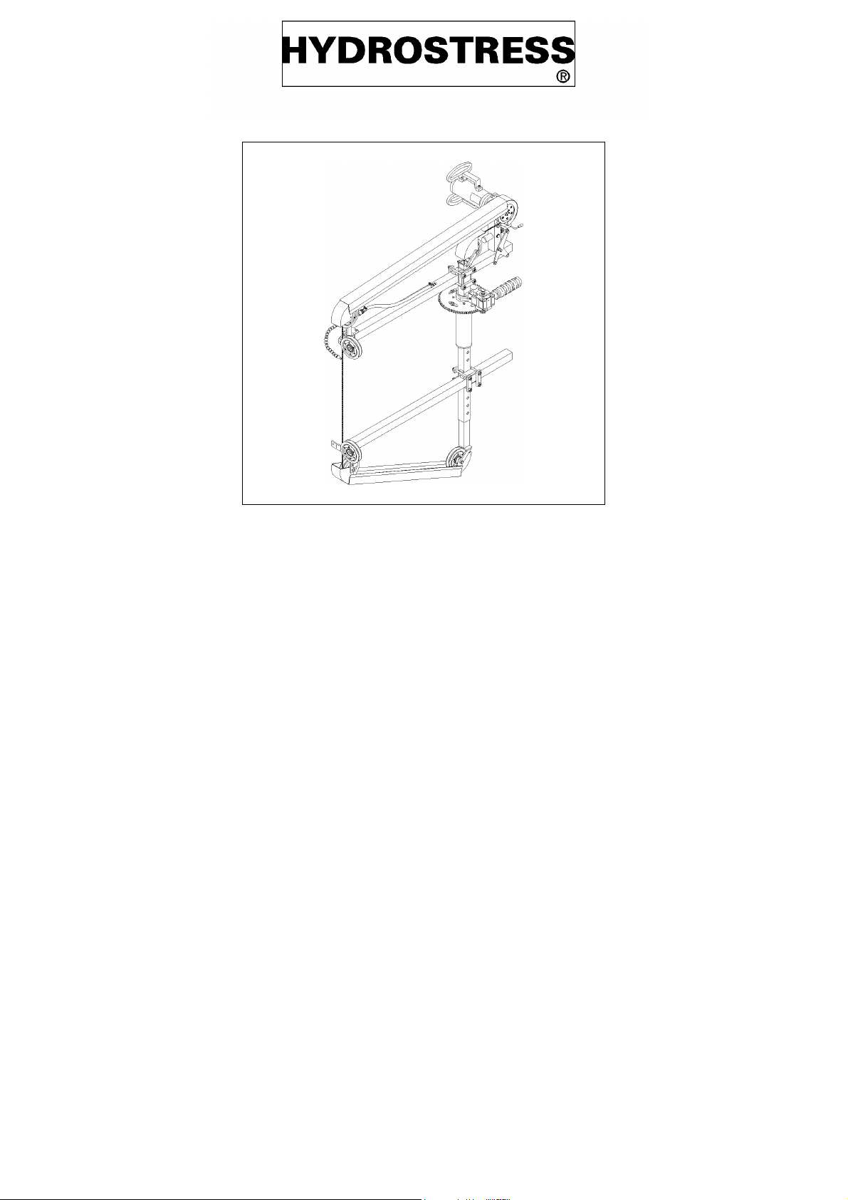
Circular wire saw system SL
Operating instructions
Spare parts list
Page 2

SL
0.1 Introduction
Dear customer,
you have decided in favor of a progressive, proven
HYDROSTRESS equipment, hence for a stand-
ard of technological leadership.
Due to our efforts in the field of quality assurance the
Circular Rope Saw Type SL represents a Swiss top
performance product:
• High sawing performance
• Reliable operation
• High mobility
• Convenient handling
• Low maintenance cost
Only original HYDROSTRESS spare parts assure
quality and compatibility.
If proper maintenance work is neglected or done
incompetently we can not fulfill the guarantee obliga-
tions set forward in our terms of delivery.
All repair work is to be made by professionally trained
persons only.
0.2 Validity of this Operation
Instruction
This Operating Instruction is exclusively valid for
the following equipment:
Circular Rope Saw Type SL Index 000
0.3 System range definition
This Operation Instruction describes the use of
the Circular Rope Saw Type S including the
matching electric drive motor type EM and the
hydraulic drive motors.
The Circular Rope Saw Type SL must only be
operated after the respective Operating Manual
has been paid attention to.
Spare parts and maintenance instructions for
the drive unit engaged in the individual case can
be found in the respective Operating Manual.
Our customer service is at your disposal to maintain
your equipment in perfect condition.
We wish you trouble-free and unproblematic wor-
king with your HYDROSTRESS equipment.
HYDROSTRESS AG
The Management
Copyright © HYDROSTRESS AG, 1998
HYDROSTRESS AG
Witzbergstrasse 18
CH-8330 Pfäffikon
Switzerland
Telefon 0041 1 950 10 74
Telefax 0041 1 950 10 18
Hotline 079 / 608 19 07
0.3.1 Operating Manuals of drive units
Indications for the use of drive units are meant
to increase the safety of operators. However for
safe operation of drive units the respective Operating Manual consulting the respective Operating Manual is indispensable!
page 2 sl9806e
Page 3

SL
0.4 Table of contents
0.1 Introduction 2
0.2 Validity of this Operation Instruction 2
0.3 System range definition 2
0.4 Table of contents 3
1 Safety instructions 4
1.1 Basic provisions 4
1.2 Designated usage 6
1.3 Before starting work 6
1.4 During sawing 7
1.5 After finishing work 7
2 Technical Data 8
2.1 Dimensions 8
2.2 Attachable equipment, hydraulic 8
2.3 Attachable electric motor, electric 9
2.4 Design 10
2.5 Function with hydraulic drive 11
2.6 Funktion electric drive 12
2.7 Protection material 13
3 Preparation for work 14
3.1 Procedure 14
3.2 Select drive unit and sawing
motor (hydraulic) 15
3.3 Calculation of rope length 16
3.4 Secure construction site 17
3.5 Secure part to be sawn out 17
4.5 Mount protection hoods 23
4.6 Water cooling 23
4.7 Connection of water in case of using a
hydraulic unit 23
4.8 Connection of water in case of using
electric motor "EM" 24
5 Sawing 25
5.1 Before sawing 25
5.2 Sawing, hydraulic 25
5.3 Sawing, electric 26
5.4 Trouble shooting 27
5.5 After sawing 27
6 Maintenance 28
6.1 Maintenance table 28
7 Repair 29
7.1 Connection and repair of rope 29
7.2 Connecting the rope by joint lock 29
7.3 Connecting the rope by repair sleeve 30
7.4 Connecting the rope by threaded lock 31
8 Transportation, shut-down , storage,
disposal 32
8.1 Transportation 32
8.2 Shut-down, storage 32
8.3 Disposal 32
8.4 Accessories 32
4Set-up 18
4.1 Fastening of system 18
4.2 Connecting the drive unit 20
4.3 Connecting the electric module 21
4.4 Mounting of rope 22
9 Spare parts list 33
sl9806e page 3
Page 4
Safety instructions SL
1 Safety instructions
1.1 Basic provisions
1.1.1 Dangers at work on construction
sites
The equipment is built in accordance with state-
of-the-art and generally accepted rules of safety
techniques. Nevertheless its operation may ef-
fect hazards to life and limb of the user or third
persons resp. damage to the equipment or to
other objects of value. Pay attention to the
special working conditions at a construction site.
Protect yourself and others within your area of
responsibility extensively against the multiple
dangers!
1.1.2 Qualification of operating personnel
The operators need to be introduced and
trained for work by experienced experts.
For maintenance and repair specifically trained
personnel has to be engaged.
HYDROSTRESS can assist you for training.
1.1.3 Read the Operating Manual and
inform your co-workers!
This Operating Manual contains important indications for
operating the equipment both
safely and economically.
The owner of the equipment needs to make sure
that the instructions of the Operating Manual are
paid attention by each and every person who
will in any possible way be dealing with the
equipment or the connected auxiliary and ope-
rating materials.
The Operating Manual has to be made available
at the working site at all times
Noise impact (sound level)
The noise level during work lies
above 90 dB(A). This noise
strain may permanently damage your hearing. Therefore during operation always wear ear
protection devices.
page 4 sl9806e
Page 5
SL Safety instructions
1.1.4 Recognize the Safety Alerts!
Danger: Pay attention to the following phrases,
their symbols (characteristics, displays, mar-
kings) and their meaning:
Danger:
Specific information for prevention of bodily injuries
Attention:
Specific information for prevention of da-
mage to the equipment
1.1.5 Personal protective clothing
During drilling, sawing, biting, and pressing of
concrete and stone
wearing protective clothing is necessary to give
protection against the following dangers:
Source of danger protective clothing:
falling pieces: helmet, steel
reinforced footwear
moving, sharp-
gloves
edged pieces:
flying stone pieces,
goggles
flying sparks:
slipping: footwear with non-slip
soles
Advice:
Specific information for economic use
of the equipment
.
noise: earmuffs
contamination of
breathing mask
respiratory tract:
sl9806e page 5
Page 6

Safety instructions SL
1.2 Designated usage
The system is designated for sawing with dia-
mond ropes of Ø11mm into the materials
quoted below.
Any different usage may create risks which are
not described in this Operating Manual and will
void any warrantee by HYDROSTRESS.
Process with this equipment exclusively:
• Concrete, rock, masonry, asphalt
Other materials are not allowed for proces-
sing, especially:
– Wood, plastics and glass
1.2.1 Sawed-off pieces
These pieces may weigh heavily. Example: A
cube of concrete of 1m edge dimension (~33")
weighs about 2.5 tons (~5600 lb.). Secure such
pieces against dropping or tipping over and
close off that area of the construction site!
1.2.2 Drive units and accessories
1.3 Before starting work
1.3.1 Static of the edifice
The sawing of large openings can impair the
static of an edifice. Therefore the sawing of large
openings must be planned in coordination with
construction static experts.
1.3.2 Tension reinforced concrete
Inform yourself if any tension rods are situated
within the range of your planned cuts. Sever
these only after explicit authorization.
1.3.3 Emergency Stop
Make sure that you can promptly stop the
machine in case of emergency (see “Emergen-
cy Stop” in this Operation Instruction)!
1.3.4 First Aid in accidents
Find out how to organize help fastest possible
in case of accident!
Use the machine or equipment exclusively with
the recommended drive units or equipment and
1.3.5 Water-, Gas and Power-lines
accessories (see “Attachable units” or “Attacha-
ble equipment” and “Accessories” in this Ope-
ration Instruction)
Make sure that such lines within your cutting or
drilling range are out of operation! Obtain infor-
mation whether such lines may be cut through!
1.2.3 Accident prevention regulations in
your country
Observe the general and particular accident
prevention regulations of trade associations and
federations in your country!
1.3.6 Reinforcement rods
Obtain information whether you may sever pos-
sibly present reinforcement rods in the course
of the cut or bore.
page 6 sl9806e
Page 7

SL Safety instructions
1.3.7 Organize your working place
Organize your working place properly! Thereby
you will considerably reduce accident hazard!
1.3.8 Lighting of working place
Provide for sufficient lighting of working place.
1.3.9 Protection gear
Never start sawing before all protection gear is
attached and in place.
1.3.10 Flushing water
Ascertain that flushing water can not spill over
into electric installations. Avoid material dama-
ges by flushing water by exercising good con-
trol of the water’s draining flow.
1.4.3 Rotating and moving parts
Keep away from the rope and the pulleys. In
order to avoid being caught by rotating or mo-
ving parts wear tight clothes, and if having long
hear, wear a hair net!
1.5 After finishing work
After work pull out the power plug of the drive
unit to prevent unintentional switching on!
1.5.1 Removal of concrete and rock
pieces
Utilize suitable lifting equipment for the removal
of those pieces, in order to avoid injuries!
1.4 During sawing
1.4.1 Rope ruptures
A rope rupture must be taken into account at any
time.
Observe the measures for avoiding rope ruptu-
res (see “Malfunction remedy”).
1.4.2 Motorized forward feed
Equipment with motorized forward feed are not
automates. During operation they must be su-
pervised at all times. A emergency shut-off must
be possible at any time.
sl9806e page 7
Page 8
Technical Data SL
2 Technical Data
2.1 Dimensions
2.1.1 Sawing diameters
min. 50 cm
max. 200 cm
2.1.2 Thickness
max. 60 cm
2.1.3 Weights
Weight 122 kg (~276 lbs.)
separable into subassemblies of max. 20 kg ea. (~43
lbs.)
2.1.4 Drive wheel
effective diameter
2.2 Attachable equipment, hydraulic
for rope grip Ø 180mm(~7-1/8”)
2.1.5 Diamond ropes
Diameter Ø 11mm (~7/8”)
Length 621 cm max. (~20’4-11/16”)
351 cm min. (~11-1/2’)
2.1.6 Cutting speed with electric motor
V = 26m/s
2.1.7 Cutting speed with hydraulic motor
See chapter 3.2
Fig.sl_conn.tif
Do not use any other
equipment!
page 8 sl9806e
Page 9

SL Technical Data
2.2.1 Particular characteristics of the
various drive units
The power output differs from drive unit to drive
unit. Therefore:
– choose correct sawing motor
– choose correct level at the drive unit
(see "Selecting drive unit and sawing motor",
Chapter 3.2.)
2.3 Attachable electric motor, electric
2.3.1 Which extension arm for what
diameter?
Fig. sl_conn2.tif
Do not use any different
electric motor or control unit!
Fig.auslzent.tif
Extension arm Ø
750 mm (~2-1/2’) 500 - 700 mm (~1’7-
1/2” – 2’3-1/2”)
1500 mm (~5’) 700 - 2500 mm (~2-
1/2’ – 8’2-1/2”)
2.3.2 The center tube
Center tube thickness "D" max.
1000 mm (~3’3-3/8”) 0.6 m (~2’)
sl9806e page 9
Page 10
Technical Data SL
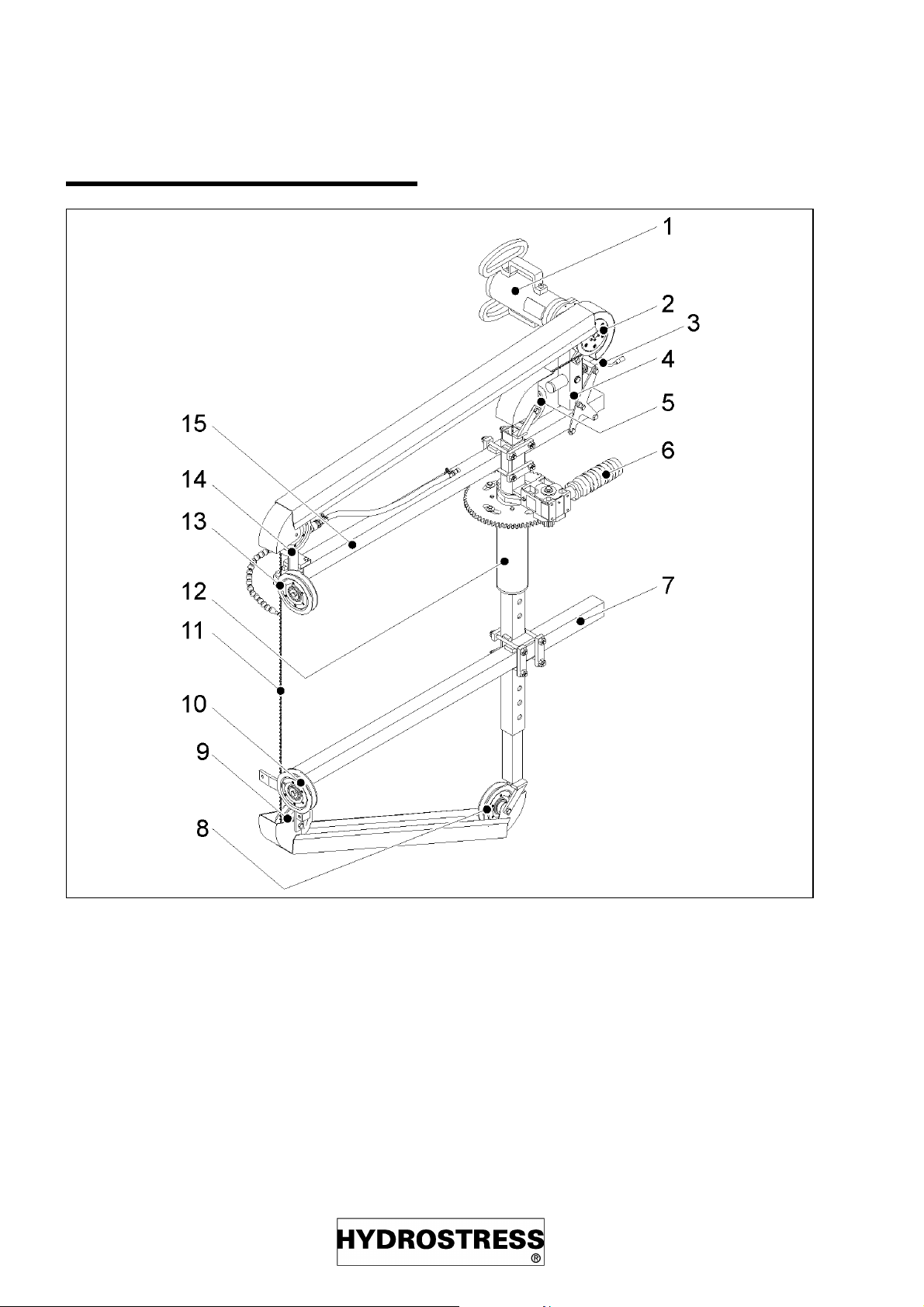
2.4 Design
Fig.aufbau.tif
1) Electric motor or hydraulic motor
2) Drive wheel
3) Crank for rope tension
4) Swivel rack
5) Central reversal pulley, top
6) Forward feed motor electric or hydraulic
7) Extension arm, bottom
8) Central reversal pulley, bottom
9) Deflection pulley, bottom
10) Guiding pulley, bottom
11) Diamond rope
12) Center tube
13) Guiding pulley, top
14) Deflection pulley, top
15) Extension arm, top
page 10 sl9806e
Page 11
SL Technical Data
2.5 Function with hydraulic drive
Hydraulic drive
2.5.1 Guiding and tightening of rope
The rope is being guided by ...
– the drive wheel (2)
– two central deflection pulleys - top and
bottom (5 and 8),
– two deflection pulleys top and bottom
(9 and 14),
– and by the guiding reels top and bot-
tom (10 and 13).
> which engages with the gearwheel circumfe-
rence at the support.
2.5.3 Rope drive, hydraulic
> When the Main circuit of the drive unit is
opened,
> the sawing motor (1) will turn and will drive
> the drive wheel (2) and thereby
> will drive the rope.
The speed of the rope is determined by...
1) ... the oil flow from the drive unit
2) ...flow intake of the sawing motor
(controllable)
2.5.4 Emergency Stop
The rope is being tightened by ...
> turning the tension spindle (3) clockwise,
> by which the swivel rack (4) tilts outward
> and the diamond sawing rope is being
tightened across the drive wheel (2)
2.5.2 Circular motion /Forward feed,
hydraulic
The movable portion of the system turns around
the center tube (12), when...
> the connected forward feed circuit at the dri-
ve unit is being opened,
> the hydraulic forward feed motor (6) will turn
> and through the transmission gear in front of
the feed motor
The system can only be stopped at the drive unit. Observe
also the Operating Manual of
the drive unit.
> will drive the cogwheel (on the feed transmis-
sion gear)
sl9806e page 11
Page 12
Technical Data SL
2.6 Funktion electric drive
Electric drive
2.6.1 Guiding and tightening of rope
The rope is being guided by ...
– the drive wheel (2)
– two central deflection pulleys - top and
bottom (5 and 8),
– two deflection pulleys top and bottom
(9 and 14),
– and by the guiding reels top and bot-
tom (10 and 13).
> which engages with the gearwheel circumfe-
rence at the support
2.6.3 Rope drive, electric
> When the main drive unit is switched on at
the electric control,
> the electric sawing motor (1) will run
> and drive the drive wheel (2)
> and thereby the rope.
The speed of the rope is determined by...
1) ...the number of revolutions of the
electric drive motor (not controllable)
2) ...the diameter of the drive wheel
(not controllable)
The rope is being tightened by ...
> turning the tension spindle (3) clockwise,
> by which the swivel rack (4) tilts outward
>and the diamond sawing rope is being
tightened across the drive wheel (2)
2.6.2 Circular motion/Forward feed,
electric
The movable portion of the system turns around
the center tube (12), when...
> the connected forward feed is switched on
at the electric control,
> the electric feed motor (6) runs
> and through the transmission gear (in front
of the feed motor)
2.6.4 Emergency Stop
The system can only be stopped at the electric control unit.
Observe also the Operating Manual of the electric control unit.
> drives the cogwheel (at the feed transmissi-
on gear)
page 12 sl9806e
Page 13
SL Technical Data
2.7 Protection material
Fig.schutz.tif
1) Splash channel long/short, top (2
pcs. ea.)
2) Splash channel long/short, bottom (2
pcs. ea.)
3) Splash shielding, deflection pulleys
(4pcs.)
4) Splash shielding, tension reel (1 pc.)
2.7.1 Protective provisions
Never start sawing before having all protective devices in
place
sl9806e page 13
Page 14

Preparation for work SL
3 Preparation for work
3.1 Procedure
Always proceed as follows:
1) Select drive unit and sawing motors
(hydraulic only)
2) Calculate length of rope
3) Secure construction site
4) Secure parts designated for sawing
out
5) Fix system solidly fast
6) Connect drive unit or electric motor
including control unit
7) Put on rope
8) Put on safeguard hood
9) Connect water
10) Start sawing
11) Conduct maintenance work
page 14 sl9806e
Page 15

SL Preparation for work
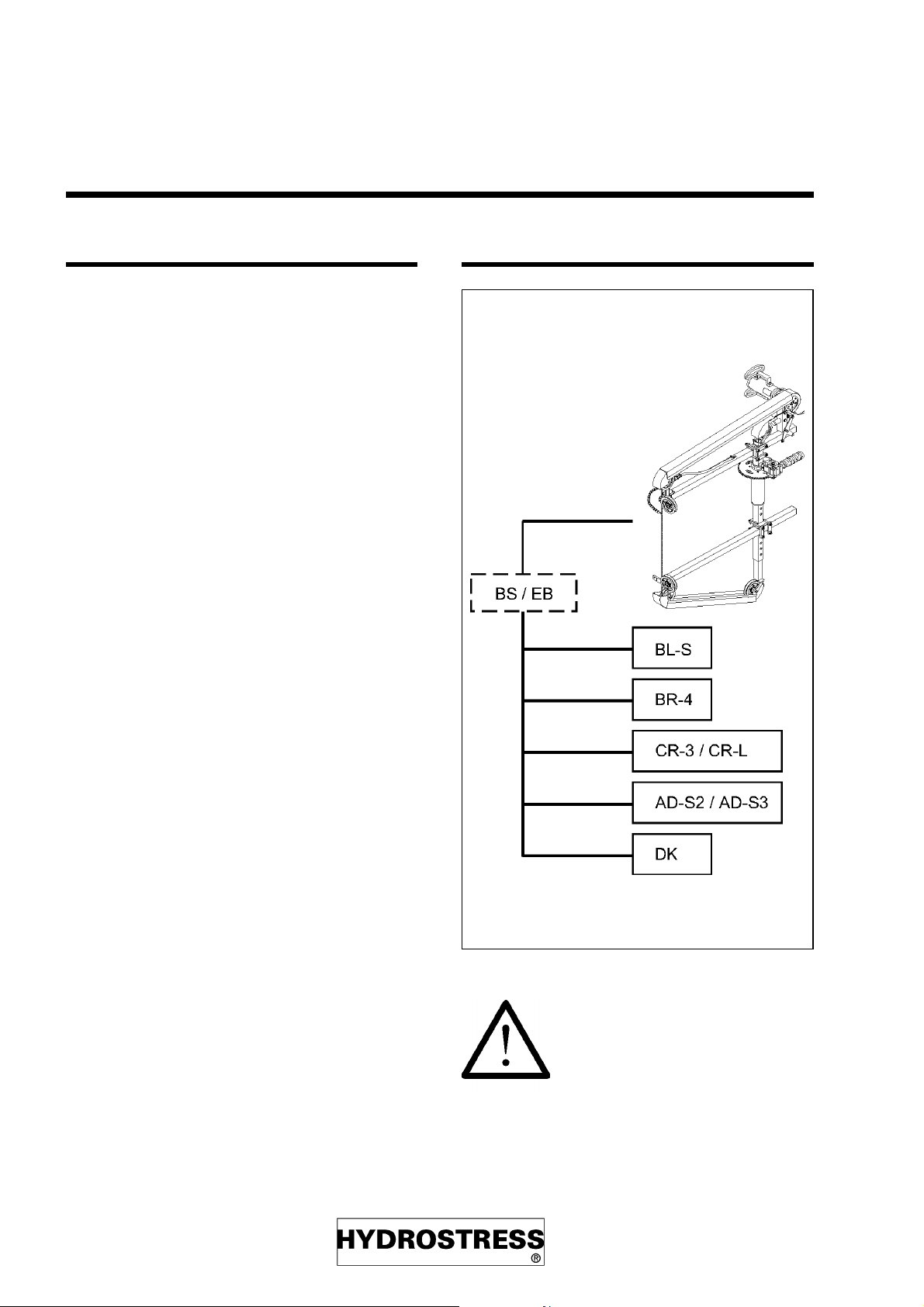
3.2 Select drive unit and sawing
motor (hydraulic)
Hydraulic drive
Through correct selection of drive unit, power
level (in case of multi-level drive units) and
Sawing motor the correct cutting speed will be
obtained, hence:
– optimum sawing performance
– best endurance of rope
– few rope ruptures
• Set the mark Ø 180 onto
the range SK-SD (1:1) and ...
• ... depending on output rate of drive unit
read out the correct sawing motor.
3.2.2 Drive units
Multi-level drive units: Use Level II or higher.
When hitting upon reinforcement steel rods one
can then switch down.
BR-3
26 l/min 30 l/min 33 l/min 40 l/min 42 l/min 45 l/min 47 l/min 50 l/min
11 ccm
22
16 ccm
18 ccm
3.2.1 Specifics for the use of the "profi
DK
(I)
m/s26 m/s
- - - 24
-- -21
CR-3
(I)
BR-4
28
CR-3
m/s
(I)
(II)
DK
(II)
34 m/s- ---
m/s 24 m/s 26 m/s 28 m/s 29 m/s
m/s 22 m/s 24 m/s 25 m/s 26 m/s
BR-3
Fig.drehztab.tif
disk"
The effective diameter of the drive wheel measures 180mm (~7-5/64”). Therefore:
CR-3
AD-S3
(III)
(II)
(II)
AD-S2
AD-S3
DK
(III)
(I)
BL-S
CR-L
Work only with the designated drive units
and only on the recommended levels
(base: v = 20...30 m/s (~22...33 yards/second))
sl9806e page 15
Page 16

Preparation for work SL
3.3 Calculation of rope length
The minimum length of the rope results from:
– Invariant = 331 cm
– two times thickness "D" of building
– "A" according to saw-Ø
from table (see bottom)
ØA
0.5 m 0.0
1.0 m 55 cm
1.5 m 115 cm
2.0 m 140 cm
2.5 m 170 cm
L
= 331 + 2 x D + A
total
Fig. dicke.tif
Example:
Thickness D = 45 cm
Ø = 1.5 m, therefore A = 115 cm
L
= 331 + (2 x 45) + 115 = 536 cm
total
3.3.1 Length of extension arm and center
tube
Depending on diameter 2 different extension
arms are available.
See "Which extension arm for what application
" and "The center tube " (Chapter 2.3.1. and
2.3.2.) and "Spare parts list".
page 16 sl9806e
Page 17

SL Preparation for work
3.4 Secure construction site
Secure danger zone and make sure that nobody
enters that zone during active work.
3.5 Secure part to be sawn out
Secure the parts to be sawed
out in their initial position, such
that...
1) ... the rope will not be jam
2) ... nobody will be endangered by uncontrollable motion of the parts
being sawed out. Depending on situation utilize these auxiliary means
or a combination thereof:
– Wedges
Example:
Securing with prop-jacks in three steps
(Cut into the ceiling, view from below!)
– Connecting straps
– Supporting it
– Suspending it by crane or from building
Secure the parts being sawed out according to
their weight (approx. 2.5 to per m
3
)
(~200 lbs. per cu.ft) and position.
Fig. sichern.tif
sl9806e page 17
Page 18

Set-up SL
4 Set-up
4.0.1 Set-up for first operation
The system is supplied ready for use. The pro-
cedures described under ”Set-up” apply also to
the first operation run of a new machine.
4.1 Fastening of system
4.1.1 procedure
Fig.mont5.tif
Fig.mont4.tif
• Drill Ø 100 mm for center tube (6)
• Drill Ø 15 mm for rope at a distance of the
sawing radius (1/2D!)
Fasten center tube assembly (6) with two
hammer plugs M12 (5)
Fig. mont3.tif
• Insert central deflection reel (3) into top of
central tube unit (6)
• and tie fast with bracket (7) (Central de-
flection reel at bottom analogous)
• Insert upper extension arm (2) into the
receptacle and tighten up (lower extension
arm analogous)
page 18 sl9806e
Page 19

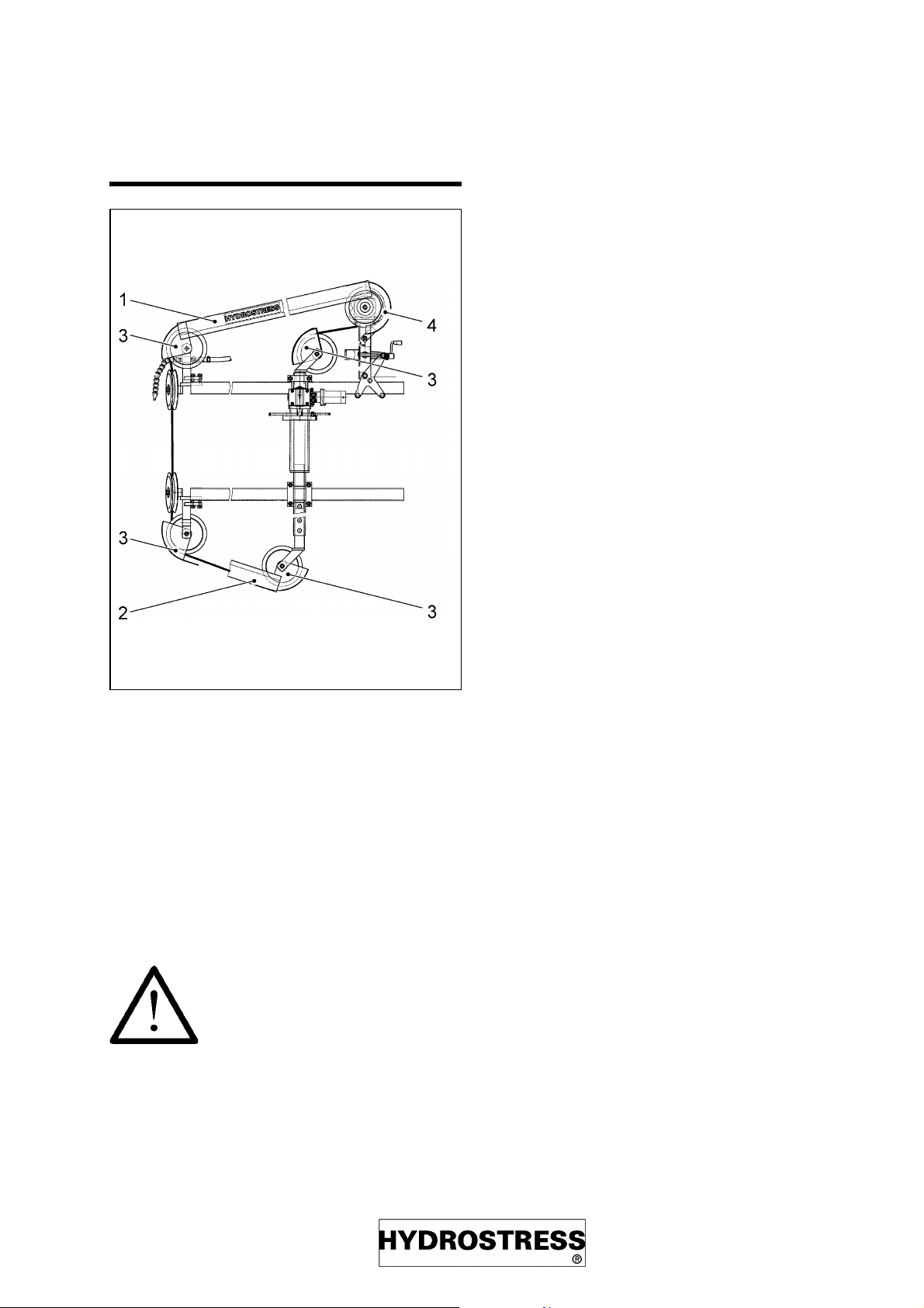
SL Set-up
• Mount top reel pair (1) in accordance with
sawing direction (bottom reels analogous)
• Mount drive tightening pulley assembly (5)
onto the upper extension arm (2)
• Put on upper shielding (4) (lower shielding
analogous)
• Mount rope (see chapter 4.3)
Fig. mont1.tif
The pairs of reels (6 and 8) must be mounted anti-symmetrically into the extension arm (2), in order to be able to cut in
the cutting direction designated by the
arrows (S). (See also chapter 4.1.2.
"Change of sawing direction ")
sl9806e page 19
Page 20

Set-up SL
Change of sawing direction
Fig. mont6.tif
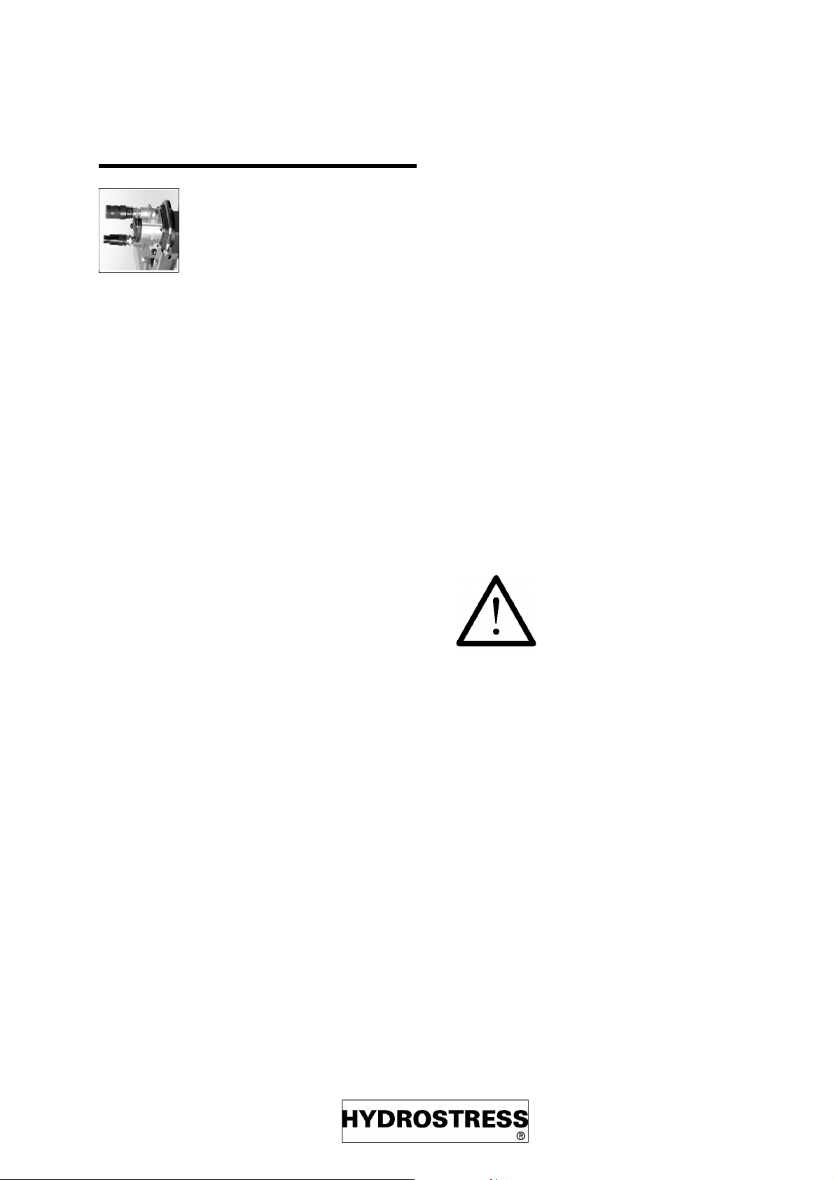
4.2 Connecting the drive unit
Hydraulic drive
Fig. mont7.tif
The reels (16) can be mounted in two different
positions depending on direction of sawing.
Fig. anschl.tif
H: Sawing motor to the main circuit
V1: Hydraulic motor for forwardb feed motion
to the feed circuit 1
V2: Forward feed 2 remains disconncted
W: Connect water ALWAYS first to the drive
unit (see also chapter 4.7. "Connecting
water for use with hydraulic drive unit ")
Never connect or decouple hoses while the drive unit is running. Set control valves to
position "0".
To observe:
– First clean couplings thoroughly.
– Connect angular shape hose cou-
plings with the sawing motor.
page 20 sl9806e
Page 21

SL Set-up
– Connect straight hose couplings with
the drive unit.
– Slide hose coupling onto the counter-
part until snapping in with an audible
click.
– Turn securing ring of the coupling.
– Hoses not engaged in operation
should be coupled among themselves
for couplings’ protection.
– Never engage couplings by force.
– If hoses appear to require force to con-
nect they are likely to be under pressure (see below).
Relieve pressure of hose.
1) Repeatedly actuate m ain or feed valve at drive unit.
2) Connec t the supplied pr ess ure relief
unit to the hose and screw in.
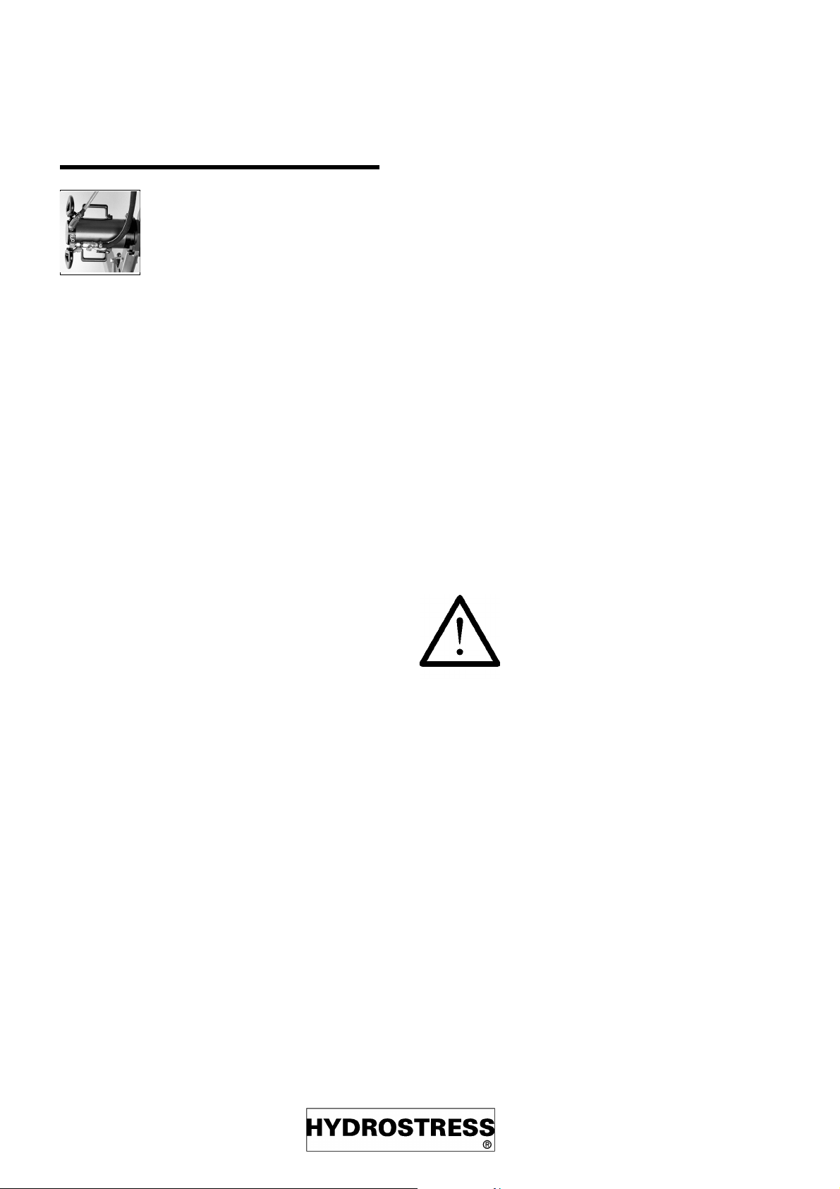
4.3 Connecting the electric module
Electric drive
Fig. anschdma.tif
1: Control handle
2: Electric connection
3: Electric connection for the main motor
4: Electric connection for the forward feed mo-
tor
5: Water
sl9806e page 21
Page 22

Set-up SL
4.4 Mounting of rope
Running direction of rope
Correct running direction of the rope is important
for satisfactory endurance.
A used rope must be run always in the same
direction as initially used.
The running direction of the rope can be recognized by the following attributes:
– Arrow on new rope
– Wear of the used rope: thin portion of
conical bead points forward
Rotational direction of the rope
sawing system
Twisting of rope
In order to avoid eccentric wear of the diamond
beads the rope needs to be twisted at the point
of connection. A new rope of Ø 11mm needs to
be twist by one turn per 1 meter of length. In the
course of increasing wear more twisting will
become necessary. The following table is valid
for a rope of a length of 10 m.
Ø of rope total
Turns
11 10
10.5 13
10 17
9.5 22
928
With threaded connectors additionally 5 turns in
order to compensate for the threading.
Fig.drehr.tif
Inserting the rope into the
equipment, connecting and
tightening
Insert the rope into the equipment in the correct
running direction, connect it (see “Connecting
and repairing of the rope”, chapter 7) and tighten
it reasonably with the crank (14).
page 22 sl9806e
Page 23

SL Set-up
4.5 Mount protection hoods
• Put on protection hood on top and bottom,
and never remove during sawing
Never keep sawing without all
the correctly mounted protection hoods!
(see spare parts list)
4.6 Water cooling
Why is water needed?
– Flushing out sawdust from the cut
– Flushing the rope of sawdust
• Open water cock
Pressure: min. 1, max. 10 bar /
5
min. 1x10
Make sure that the water supply is not
interrupted during operation.
Pa, max. 10x105Pa
– Cooling the rope
– Cooling of electric motor, in case of
using EM (Water feeder connected directly to the motor)
– Cooling of the electric motor and the
oil cooler, in case of using a hydraulic
drive unit (Water feeder connected to
the equipment)
4.7 Connection of water in case of
using a hydraulic unit
Hydraulic drive
1) Connec t water feeder with coupling
to the water nipple of the hydraulic
unit
2) Connect water hose of the hose
package between the drive unit and
the nipple of the upper reel pair
3) Dir ect water spout onto the r ope be-
fore switching on
Fig.wasser.tif
4) W ater input to the unit (1)
5) Ex tend water hos e of the hose
package by the supplied water hose
and connect to SL unit (2).
6) Dir ect water spout onto the r ope be-
fore switching on
sl9806e page 23
Page 24

Set-up SL
4.8 Connection of water in case of
using electric motor "EM"
Electric drive
1) Connec t water feeder with coupling
to the water nipple of the electric motor
2) Connect supplied water hose between the electric motor and the
nipple of the upper reel pair
3) Pos i tion water spout befor e switching on
• Open water cock
Pressure: min. 1, max. 10 bar /
5
min. 1x10
Pa, max. 10x105Pa
Fig.waansdma.tif
Make sure that the water supply is not
interrupted during operation.
page 24 sl9806e
Page 25

SL Sawing
5 Sawing
5.1 Before sawing
• check if all screws are fastened tightly
• control rope tension and if necessary
readjust (A) with the crank (3)
5.2 Sawing, hydraulic
Hydraulic drive
Switching water on
• Open water cock at drive unit
Switch on drive unit
• Set all valves to position "0"
• Start drive unit (see Operating Manual of
drive unit)
Select level
Fig. vors1.tif
• With multi-level drive units, select the pro-
per level
(see "Selecting drive unit and sawing motor ”, chapter 3.2.)
Switch on rope drive
• Set main valve at the drive unit to position
"I"
The rope will now be moving (C)
Switch on forward feed (B)
Increase forward feed pressure up to...
... main pressure: 100...150 bar
sl9806e page 25
Page 26

Sawing SL
When hitting upon reinforcement steel structu-
When hitting upon reinforcement steel
structures reduce main pressure to 100
bar by reducing forward feed pressure.
Stopping the rope
res the load of the rope will in all cases be
adjusted for optimum relation by the automatic
feed unit through reducing the forward feed
pressure.
• Switch off forward feed
• Let the rope run freely for a few seconds
• Switch off rope drive
5.3 Sawing, electric
Electric drive
Switch on water
• Open water cock at the electric motor
Optimum forward feed pressur e
Fig. vordruck.tif
Switch on electric motor/rope drive
• Push button at electric control unit DM-A
• Wait for the electric motor to start (centrifu-
gal force coupling)
The rope will now be moving. (C)
Switch on forward feed (B)
The forward feed speed is load dependent always regulated for the optimum range by the
automatic feed control unit.
• The forward feed pressure is to be set in
such a way as to have the rope enter into
the building object under an angle of approx. 45°.
1) W ith less slanted rope entry the cut
will become less accurate
2) W ith steeper rope entry the cutting
performance will be low
Stopping the rope
• Switch off forward feed
• Let the rope run freely for a few seconds
• Switch off rope drive
page 26 sl9806e
Page 27

SL Sawing
5.4 Trouble shooting
• Observe also the Operating Manual of the
drive unit
In case of rope rupture
• excessive forward feed pressure
• to narrow radii > forward feed too fast and
rope tension too low
• Reinforcement elements being sawed with
a too narrow wrap-around radius > forward
feed too fast and rope tension too low
• rope connecting joint too long (=to stiff) >
use shorter pressed sleeve joint
In case of asymmetric rope wear
Diamond beads getting pushed
together
• Plastic gets soft because rope is being coo-
led insufficiently
Rope getting pulled out of joint
sleeve
• Squeezed portion of rope in joint sleeve
too short
If the rope does not run despite the
electric motor is running
• Replace centrifugal weights of the electric
motor
5.5 After sawing
• too high forward feed pressure
• rope not properly twisted (see "Rope twi-
sting " chapter 4.4.3.)
In case of insufficient cutting
performance
• Cutting speed too low
(see "Selecting drive unit and sawing motor ")
If rope slips on drive wheel
• Rope tension too low
• Drive wheel cover band worn too much
Excessive rope wear
• too little water
• Switch off drive unit or electric motor
• Close water cock
• Pull out power plug
• Remove protection hoods
• Wash off Circular Rope Saw Type SL with
water
• Dismantle and remove rope
• Conduct daily maintenance work
(see "Maintenance", chapter 6)
• Cutting speed too low
• Running direction of rope inverted
sl9806e page 27
Page 28

Maintenance SL
6 Maintenance
6.1 Maintenance table
Disconnect power plug before
any maintenance work
Conduct the following maintenance work within
the designated periods in order to warrant:
– Safety for the user
– Optimum performance
– Ready to use at any time
interval activity remarks
GDLO\ FKHFNUROOHUOLQLQJIRUZHDU UHSODFHOLQLQJEHIRUHLWLVFRPSOHWHO\
ZRUQRII
FOHDQV\VWHP
FKHFNGHIOHFWLRQUROOHUVIRUZHDU
\HDUO\ PDMRUVHUYLFLQJ PD\EHFDUULHGRXWE\
+<'52675(66RUDQDXWKRUL]HG
+<'52675(66UHSUHVHQWDWLRQRQO\
Fig. wart_d.vpo
page 28 sl9806e
Page 29

SL Repair
7 Repair
7.1 Connection and repair of rope
Do not join ropes with different degrees
of wear:
Difference of the two Ø: max. 0.2mm
(~8 mil)
The rope can be joined or repaired by the following locking devices:
– Joint lock
– Repair sleeve
– Threadlock
Needed are:
– Pressing tongs, sleeve, knife
– Angular grinder/shearing cutter
additionally for joint lock
7.2 Connecting the rope by joint lock
Fig.sk2_glvs.tif
– Mounting kit for joint lock
Pressing the lock on
1) Cut r ope at both ends at 11 mm distance from the first bead (Attenti-
on: take care to make a straight cut).
2) Rem ov e rubber sleev ing cleanly by
pulling reinforcement spring off with
pliers, and shorten free rope ends to
max. 8 mm.
3) Slide loos e fork head part of the joint
lock onto the rope end (blank portion
of rope must extend to the bore
dead end)
4) Pr ess with TYROLIT-Original pressing tongs.
5) Slide the pr eassembled lock part
onto the other rope end (similar to
pt. 3)
6) Pr ess as described under pt. 4
sl9806e page 29
Page 30

Repair SL
Closing the lock
1) Twist rope according to instruction
(see application guide supplied with
the rope)
2) Connect the two pressed on lock
parts with the bolt supplied with the
lock kit, by a few hammer strokes.
Opening the lock
1) Dr ive out bolt by a few ham mer st rokes.
2) The rope can be reconnected using
a new replacement bolt which is
supplied with the lock kit resp. can
be ordered separately.
7.3 Connecting the rope by repair
sleeve
Pressing on of lock
1) Cut r ope at both ends ac cor ding to
drawing at 12 mm resp. 9 mm distance from bead (Attention: take
care to make a straight cut). Never
mount the locks directly behind the
rope beads as rigid portions will lead
to untimely rope rupturing.
2) Rem ov e rubber sleev ing with reinforcement spring by pulling off with
pliers.
3) Slide the r ubber rings s upplied with
the lock kit onto the blank rope ends
(important for maintaining flexibility
of the rope within the lock range)
4) Slide joint loc k par t onto the rope
end (blank portion of rope must extend to the bore dead end) and take
care that the threaded stud points always to the forward running direction. (pay attention to the direction
arrow on the rope)
5) Press lock part with T YROLIT-Original pressing tongs and pressing inlay. The pressed
Fig.seilrep.tif
The range available for pressing is separated by
a ring groove from the threaded portion on the
lock
6) Side the 2. loc k par t onto the other
rope end ( similar to pts.3 + 4) and
press as under (Pt. 5).
page 30 sl9806e
Page 31

SL Repair
7.4 Connecting the rope by threaded
lock
Pressing on of lock
• Procedure similar to pt. 7.3.
Closure of lock
• Twist rope according to instruction (see
application guide supplied with the rope)
• The rope needs to twisted by additional 5
turns in order to compensate for the
thread turns of the lock.
• Screw the two lock parts together –coun-
ter clock thread.
Opening of lock
1) Open the loc k by turning cl ock wise
with the help of a waterpipe pliers.
2) Befor e repeated closing the loc k
should be inspected for wear and if
need be replaced by a new lock.
sl9806e page 31
Page 32

Transportation, shut-d own , storage, disposal SL
8 Transportation, shut-down , storage, disposal
8.1 Transportation
The system is a high value technical system.
Protect it against damage in transportation:
– Dismantle rope
– Do not deposit any parts onto or side-
wise to the sawing system
The rope sawing system
weighs approx. 122 kg (~270
lbs.). Disassemble it for transportation and carry the individual parts (max. 20 kg, ~45 lbs.)
with caution, and if possible
twosome, to avoid back damage and accidents.
8.2 Shut-down, storage
The system consists to some extent of material
which may corrode. If out of use for ext periods
proceed as follows:
– Oil and store in a dry place
8.3 Disposal
The system consists of the following materials:
– Aluminum
– Steel
– Rubber
– Rubber/nylon fabric
– Synthetic grease
– Plastics
Obtain information on the regulations on disposal in your country.
8.4 Accessories
#TVKENG 1TFGT0Q
4XLFNH[FKDQJHNLW$=)=IRUIDVWHUPRXQWLQJDQG
H[FKDQJLQJ
RIK\GUDXOLFPRWRUV +6$=
5RSHFXWWLQJVKHDUVFRPSOHWHZLWKWKUHDGHGVOHHYHDQG
UHSDLUVOHHYH =8+7
page 32 sl9806e
Page 33

SL Spare parts list
9 Spare parts list
Ordering information
For orders of spare parts we need the following
information:
– Equipment type according to type pla-
te (e.g. L Index 000)
– Serial number according to type plate
(e.g. 12136)
– Spare part number according to spare
parts list (e.g. 08W7-75648-02)
For orders, questions and information please
contact the allotted branch office (see below).
Fig.typ.tif
Unsere Vertretung our branch office notre f iliale la nostra rappresentanza
sl9806e page 33
Page 34

Fig.sl_expl2.tif
Page 34
SL9910
Page 35

99MS-60114-50 3401019 Drive Wheel Comp.
SL9910
1 99MS-60139-06 3401943 IdlerPulley Ø 200 mm standard 6
2 0000-60114-01 3400182 Central tube 1
3 0000-60114-02 3401266 Cross Pipe pc. 2
4 0000-60114-03 n/a Cutting pulley support short 2
5 0000-60114-05 341267 Cross clamp 8
6 0000-60114-06 3400936 Extension tube 2
7 0000-60114-35 3400937 Extension tube short 2
8 0000-60114-07 3401200 Pulley support
9 0000-60114-08 n/a
10 0000-60114-09 n/a Plate 2
11 0000-60114-38 n/a Plate for gear 1
12 0000-60114-12 n/a Support 1
13 0000-60114-13 n/a Bushing sleeve 4
14 0000-60114-14 n/a Threaded pivot block with bushing 1
15 0000-60114-15 n/a Spacer 1
16 0000-60114-16 n/a Pivot block handle 1
17 0000-60114-17 n/a Shaft carriage 1
18 0000-60114-18 n/a Worm gear 1
19 0000-60114-22 n/a Central tube 1
20 0000-60114-25 3401256 Spur-toothed wheel 1
Pulley support long 1
short 1
21 0000-60114-26 n/a Support 1
22 0000-60114-28 n/a Pan head screw 3
23 0000-60059-32 n/a Flange 1
24 0000-60059-33 n/a Ring 1
25 0000-60072-26 n/a Flange plate 1
26 0000-60086-51 n/a Snap ring 2
27 0000-60086-52 n/a Spacer 1
28 0000-60086-53 3401050 Driven shaft 1
Page 35
29 0000-60086-54 n/a Flange 1
30 0000-60086-68 3401951 Lining 1
Page 36

Fig.sl_expl2.tif
Page 36
SL9910
Page 37

99MS-60114-50 3401019 Drive Wheel Comp.
SL9910
31 0000-60114-39 n/a Pinion 1
32 0001-52747-01 n/a Lever 1
33 0000-60114-31 n/a Splash Flap 6
34 0000-60114-32 n/a Splash Flap 1
35 0000-60114-33 n/a Splash drain 2
36 0000-60114-34 n/a Splash drain short 2
37 0002-52047-04 3400339 Coupling Danfoss 1
38 0000-60087-31 Coupling shaft 1
39 0000-60087-29 n/a Danfoss flange 1
40 13K1-01924-00 3400338 Star coupling plate 1
41 13V7-03220-20 n/a Lamellar plug 20 1
42 13V7-03250-50 n/a Lamellar plug 50 1
43 13P1-09059-05 n/a Bellow 1
44 02S1-03015-50 3400594 Circlip arbor 2
45 01S1-08016-00 n/a Hexagonal screw 4
46 01S1-08045-00 n/a Hexagonal screw 1
47 01S1-12040-00 3402151 Hex screw 2
48 01S1-12025-00 n/a Hex head cap screw 3
49 01S1-12030-00 n/a Hexagonal screw 4
50 01S1-12055-00 n/a Hex head cap screw 4
51 01S1-12070-00 3401165 Hex head cap screw 1
52 01S1-12100-00 n/a Hex head cap screw 3
53 01S1-06025-00 n/a Hex head cap screw 4
54 01U2-12028-50 n/a Washer 6
55 01U2-12037-50 3403024 Washer 4
56 01U6-08035-50 n/a Washer 1
57 01M1-12000-00 3402015 Hex nut 3
58 01M3-12000-60 3401921 Stop nut
Page 37
59 04W2-00007-00 n/a Nut 1
60 05L1-00040-50 3401116 V-Seal 2
Page 38

Fig.sl_expl2.tif
Page 38
SL9910
Page 39

99MS-60114-50 3401019 Drive Wheel Comp.
SL9910
61 01I1-06020-00 n/a Allen head screw 6
62 04Z3-03207-00 3401945 Angular ball bearing 1
63 01I1-06050-00 n/a Allen head screw 6
64 01M1-06000-00 3402059 Hex Nut 6
65 01I1-06030-00 3400085 Allen head screw 6
66 01I1-10040-00 n/a Allen head screw 2
67 01I1-08016-00 3402017 Allen head screw 4
68 01I1-06010-00 n/a Allen head screw 1
69 01I1-06016-00 3400693 Allen screw 2
70 07S2-07013-13 3400683 Hose nipple 1
71 12Z2-38639-24 n/a ABA Hose Clip 15-24 2
72 12W1-00525 n/a Hose no. 525 1
73 07S2-07013-00 3400359 Water coupling female 1
74 07S2-17217-38 3400427 Plug in nipple 3/8" 1
75 12Q2-51804-00 3403016 Loc-Line threaded nipple 1
76 12Q2-51800-00 3401175 Loc-Line joint sleeve lrg 20
77 12Q2-51806-00 3400769 Loc-Line nozzle 6mm 1/2" 1
78 02L1-06012-00 n/a Grooved pin 6x12 2
79 02W1-00807-32 n/a Shaft key 10x8x70 1
80 XXKL-00000-02 n/a HS-Logo sticker 4
81 0002-54457-02 3402010 Type plate small
82 02L2-00040-08 n/a Grooved drive stud
Page 39
Page 40

Page 40
SL9910
Fig.200_9907.tif
Page 41

Pos Stk 964254 99MS-60139-06 Umlenkrolle Dm 200 Umlenkrolle Dm 200
SL9910
1 1 977529 0000-60086-68 3401951 Lining 200mm
2 2 964209 0000-60139-01 3401059 8"Wheel Hub
3 8 971711 01I1-06025-00 3400865 Allen head screw
4 8 971677 01I1-04008-00 2900761 Inbus-S
chraube M 4x
5 1 964218 0000-601396 1 964210 0000-60139-02 3400856 Bushing
7 1 972000 02S1-03515-50 3400857 CIRCLIP
8 2 972149 04R3-06007-00 3402057 Ball Bearing 6007
9 2 964355 05O1-00620-15 2702791 O-Ring Dm 62x1.5
10 8 979307 01M1-06000-00 3402059 Hex Nut
11 1 964213 0000-60139-05 3401186 Pulley Hub
12 1 964212 0000-60139-04 3402157 Rear Cover
13 1 969143 05D1-45524-00 3401866 Seal
14 1 971916 01S1-12030-00 n/a Hex screw M12x30
14 1 979338 01S1-12055-00 n/a 6kt-Schraube M12x55
14 1 971922 01S1-12070-00 3401165 Hex Screw
03 3402156 Front Cover
Page 41
 Loading...