

Page 1
1
800114
Français p. 7
Español p. 13
18
CUIDADO Y MANTENIMIENTO
800114
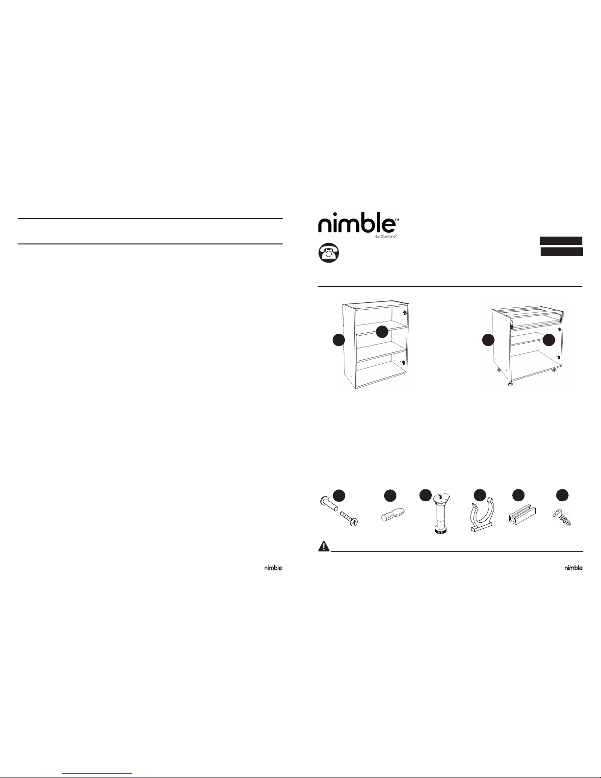
WALL BOX
(A) Wall Box (x1)
(B) Adjustable Shelves (Quantity varies by box size)
(AA) Connecting Bolts & Nuts (x4)
(BB) Shelf Pins (Quantity varies by number of shelves)
BASE BOX
(A) Base Box (x1)
(B) Adjustable Shelves (Quantity varies by box size)
(AA) Connecting Bolts & Nuts (x4)
(BB) Shelf Pins (Quantity varies by box size)
(CC) Adjustable Legs (x4)
(DD) Toekick Clip (x4)
(EE) Toekick Attachment Plate (x4)
(FF) Screws (#6 x 5/8 in. at head Phillips Type A)
AA
BB
CC DD EE FF
WALL AND BASE BOX INSTALLATION
Questions?
Call customer service at 1-844-614-0002, 8 a.m. - 6 p.m., EST, Monday - Friday, 9 a.m. - 1 p.m. Saturday
B
BA A
SAFETY INFORMATION
Please read and understand this entire manual before attempting to assemble, operate or install the product.
PACKAGE CONTENTS
Note: Hardware not shown actual size. Line art is representational only. Purchased product may vary in appearance.
Use limpiadores o productos de limpieza no abrasivos que no contengan solventes.
A continuación un resumen general de lo que se incluye y se excluye en la Garantía Limitada total, así como otras limitaciones y descargos de
responsabilidad importantes. Puede llamar al 1-800-766-1126 si desea obtener una declaración completa de la Garantía Limitada, con todas
las exclusiones, limitaciones y descargos de responsabilidad.
Se garantiza que este Producto está libre de no conformidades en sus materiales y en su fabricación para un uso normal, desde la fecha de
su compra y durante el tiempo en que el comprador original viva en la residencia en que el Producto se instaló por primera vez y mantenga la
propiedad de dicha residencia. La presente Garantía Limitada es sólo para uso residencial en los Estados Unidos, Canadá o México y termina
cuando el comprador original transera la propiedad de la casa o ya no resida en ella. De existir alguna inconformidad en cuanto al material o
la fabricación durante dicho período, el Vendedor reparará o sustituirá el Producto a su propio criterio, sin costo alguno. A modo de ejemplo,
la Garantía Limitada no cubrirá daños ni averías ocasionadas por abuso, uso incorrecto, vandalismo, negligencia o accidentes, desgaste
o deterioro natural, instalación inadecuada, limpieza o mantenimiento inadecuados (como el uso de limpiadores abrasivos, que contengan
cloro, esponjas con supercies abrasivas o estropajos de acero), condiciones ambientales que afecten con el tiempo el color o la apariencia
del Producto (como la luz solar, el humo, la temperatura o humedad extremas u otras condiciones atmosféricas), incendios, inundaciones o
Casos Fortuitos. La Garantía Limitada NO cubre los daños y perjuicios indirectos que resulten de no conformidades, ni de los costos de la
mano de obra por la instalación o la desinstalación, ni de los costos de transportación para devolver el Producto si el Vendedor lo requiere;
la responsabilidad del Vendedor en ningún caso excederá el precio de compra del Producto. HASTA DONDE PERMITA LA LEY, SE NIEGA
EL RESTO DE LAS GARANTÍAS, SEAN IMPLÍCITAS O EXPRESAS, INCLUIDAS TODAS LAS GARANTÍAS DE COMERCIABILIDAD O
IDONEIDAD PARA ALGÚN PROPÓSITO ESPECÍFICO. La Garantía Limitada le ofrece al comprador derechos legales especícos, pero el
comprador puede además tener otros derechos que pueden variar de un estado a otro, o de una provincia o territorio a otros. Puede llamar al
servicio de Atención al Cliente al número 1-800-766-1126 para más información.
GARANTÍA LIMITADA
Impreso en los EE. UU
nimble es una marca registrada
MasterBrand Cabinets, Inc. Todos los derechos reservados.
Installation Videos at: benimble.com Installation Videos at: benimble.com
Toekick sold separately
Page 2
2
INSTALLATION INSTRUCTIONS
INSTALLATION INSTRUCTIONS
PREPARATION
Before beginning assembly of product, make sure all parts are present by comparing parts with package contents list. If any part is
missing or damaged, do not attempt to install the product.
Tools required for Installation (not included): #10 x 2 ½ in. Washer-Head Cabinet Box Installation Screws, Phillips
Screwdriver, Drill, 3/32 in. Drill Bit, Pen or Pencil, Carpenter’s Level, Tape Measure, Stud Finder, Straight Edge, Saw and
Shims; May need 1 in. taper head wood screws depending on room layout.
3
Plumb Line
Use level to draw line
Mark top
line for wall,
tall cabinets
Level
Straight edge
High Point
Corner is out
of square
Corner is out
of plumb
(not vertical)
Floor not level
Shim As Necessary
Utilisez des cales si nécessaire.
Puede colocar cuñas según
se requiera.
Shim
WOOD DUST CAUTION!
SAWING, SANDING OR MACHINING WOOD PRODUCTS CAN PRODUCE WOOD DUST WHICH CAN CAUSE A FLAMMABLE OR EXPLOSIVE HAZARD.
WARNING: Modications to this product can release wood dust, a substance known to the State of California to cause cancer.
Wood dust may cause lung, upper respiratory tract, eye and skin irritation. Some wood species may cause dermatitis and/or respiratory allergic effects.
The International Agency for Research on Cancer (IARC) has classied wood dust as a nasal carcinogen in humans.
• Avoid dust contact with ignition source.
• Avoid prolonged or repeated breathing of wood dust in air.
• Avoid dust contact with eyes and skin.
FIRST AID: If inhaled, remove to fresh air. In case of contact, ush eyes
and skin with water. If irritation persists, call a physician.
FOR A WOOD DUST MSDS (Material Safety Data Sheet), CONTACT www.masterbrand.com/regulatoryinformation
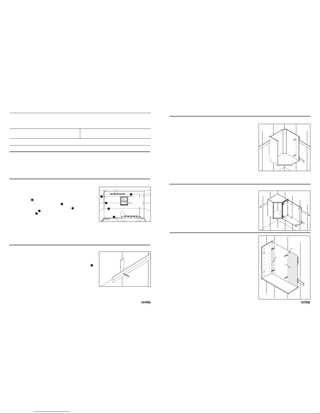
STEP 3: Wall Box Installation
3a Start by hanging the wall corner box in the corner of the room.
3b If Install Guide Rails are used, hook the cabinet box onto the guide rail using
the notched portion of the box back.
3c Measure from the corner of the wall to the stud marks and transfer the marks to
the inside of the box.
3d Drill through the wall box back where the support rails are located and into the
pre-located studs with a 3/32 in. diameter drill bit, approximately 2 in. deep.
Holes should not be drilled within 2 in. of any inside edge of the box
3e Insert the 10 x 2 ½ in. Washer-Head Cabinet Box Installation Screws (not
included), into the holes until they are nearly tight.
3f Do not tighten the screws until you nish all nal leveling and shimming.
3g Check the front, sides and bottoms of all wall boxes with a level. After the box
is level and square, fully tighten the 10 x 2 ½ in. Washer-Head Cabinet Box
Installation Screws.
3h Install the adjustable shelves (B) using the provided shelf pins (BB).
CAUTION: Never use nails to mount boxes. The use of nails will void your factory
warranty, written or implied. Cement, block, brick or tile walls require anchors for
screws or toggle bolts.
STEP 4: Adjacent Wall Box Installation
4a Continue with your wall box installation by placing the next box on the guide
rail. Be careful to line up the bottom horizontal edges.
4b With the provided connecting bolts and nuts (AA), fasten the two boxes
together through the 4 pre-drilled holes located on each end of the box.
4c Depending on the conguration of your kitchen, some boxes may need to be
fastened together with standard 1 in. taper head wood screws (not included).
4d Shim the box as necessary to make it level.
4e Fasten the box to the wall as previously mentioned in Steps 3d-3h.
4f Continue installing the remainder of your wall boxes in the same manner.
Note: If installing a single wall box, follow instructions shown in Step 5 for proper
installation.
STEP 5: Single Wall Box Installation
5a Follow Steps 1-3 to prepare the wall for your box.
5b The cabinet box should be located so the studs you plan to attach to do not fall
within 2 in. of the inside vertical edges.
5c Make sure the box is level and square.
5d Shim to ll uneven areas between the wall and back of the box. Failure to do
this step could result in damage to the cabinet box.
5e Pay close attention to the locations where you plan to screw the boxes to the
wall to make sure there are no voids between the box and wall.
5f Drill through the box back into your pre-located stud(s) with a 3/32 in. diameter
bit, 2 in. deep in a minimum of 4 places.
5g The holes should be no closer than 2 in. and no further than 12 in. from any
inside vertical edge and 2 in. from the inside of the top and bottom. (see
illustration)
5h The holes should also be located at the top and bottom of the cabinet box back.
The use of 10 x 2 ½ in. Washer-Head Cabinet Box Installation Screws (not
included) is required.
STEP 1: Prepare For Box Installation
1a Remove base boards and other objects on the wall area where the boxes are
to be installed. Using a straight edge and a level, nd the high point in the oor
where the boxes are to be installed.
1b From the high point, mark a level horizontal line on each wall where the boxes
will be attached 1 .
1c Mark another line 35 in. up from the rst line 2 .
1d From those lines mark another horizontal line 54 in. up 3 for the bottom of wall
boxes or 77-3/4 in. up 4 if you are using the optional Install Guide Rail for wall
boxes and 84 in. up 5 for utility box heights.
1e Locate wall studs with a stud nder and mark them where the boxes are to be
installed. Always install boxes to the wall studs.
1f Re-measure the area to conrm your boxes will t in the space.
1g Remove adjustable shelves (B) from boxes before installation.
NOTE: All boxes are subjected to quality inspections before leaving the
manufacturing facility. Damage may occasionally occur in handling between
the manufacturing facility and the nal destination. Inspect each box carefully. If
damage is discovered, place the box back in the carton and notify your retailer.
STEP 2: Guide Rail Installation (optional)
2a Determine the length of your run of wall box boxes. Then cut the guide rail 1 to
2 inches shorter, so the guide rail will not extend beyond the box boxes. If you
are installing a Corner Wall Box, keep the guide rail 6 in. out from the corner of
the wall to allow for install exibility in case your wall is out of square.
2b Mark the center of the guide rail and use the pre-located line at 77-3/4 in. 4
to mount the Install Guide Rail for wall boxes. Place the small surface of the
Install Guide Rail against the wall as pictured.
2c Pre-drill through the Install Guide Rail into wall studs with the 3/32 in. drill bit
approximately 2 in. deep.
2d Screw the Install Guide Rail to the wall with the 10 x 2 ½ in. Washer-Head
Cabinet Box Installation Screws (not included) while making sure the Install
Guide Rail is level. Shim where necessary to keep the Install Guide Rail level
and plumb.
NOTE: The Install Guide Rail assists in installation. Each cabinet box itself must
still be screwed to the wall. Utility boxes do not use the guide rail. Ensure Install
Guide Rail is not mounted to the wall where a utility box will be located.
Shim
Shim
12”
max
2”
min
2”
min
Installation Videos at: benimble.com Installation Videos at: benimble.com
5
4
3
2
1
Page 3
5
4
5 inches
TAB
Drawer Box
Release
1 1/2 IN.
20
7
/
8
in.
1 1/2 IN.
1 1/2 IN.
20
7
/
8
in.
1 1/2 IN.
STEP 5: Single Wall Box Installation (cont’d)
5i Cement, block, brick or tile walls will require screw anchors (not included).
5j Insert the 10 x 2 ½ in. Washer-Head Cabinet Box Installation Screws (not
included) into the holes until they are nearly tight. Make sure that the back if
fully supported with shims, as needed, and does not bow into any imperfections
in the wall.
5k Check that the box is level and plumb; Adjust as needed.
5l Fully tighten the screws and install the adjustable shelves (B).
NOTE: The Install Guide Rail assists in installation. The cabinet box itself must still
be screwed to the wall.
Important: Structural modications of a wall box can signicantly weaken the box.
For this reason modications, such as cutting the back to clear wall obstructions is
not recommended. If an obstruction exists, we suggest you rst try to use box(s)
that do not require modications. If modication is required, the warranty of the
box is void and it is the responsibility of the installer to take appropriate steps to
compensate for any loss of strength or support due to the modication.
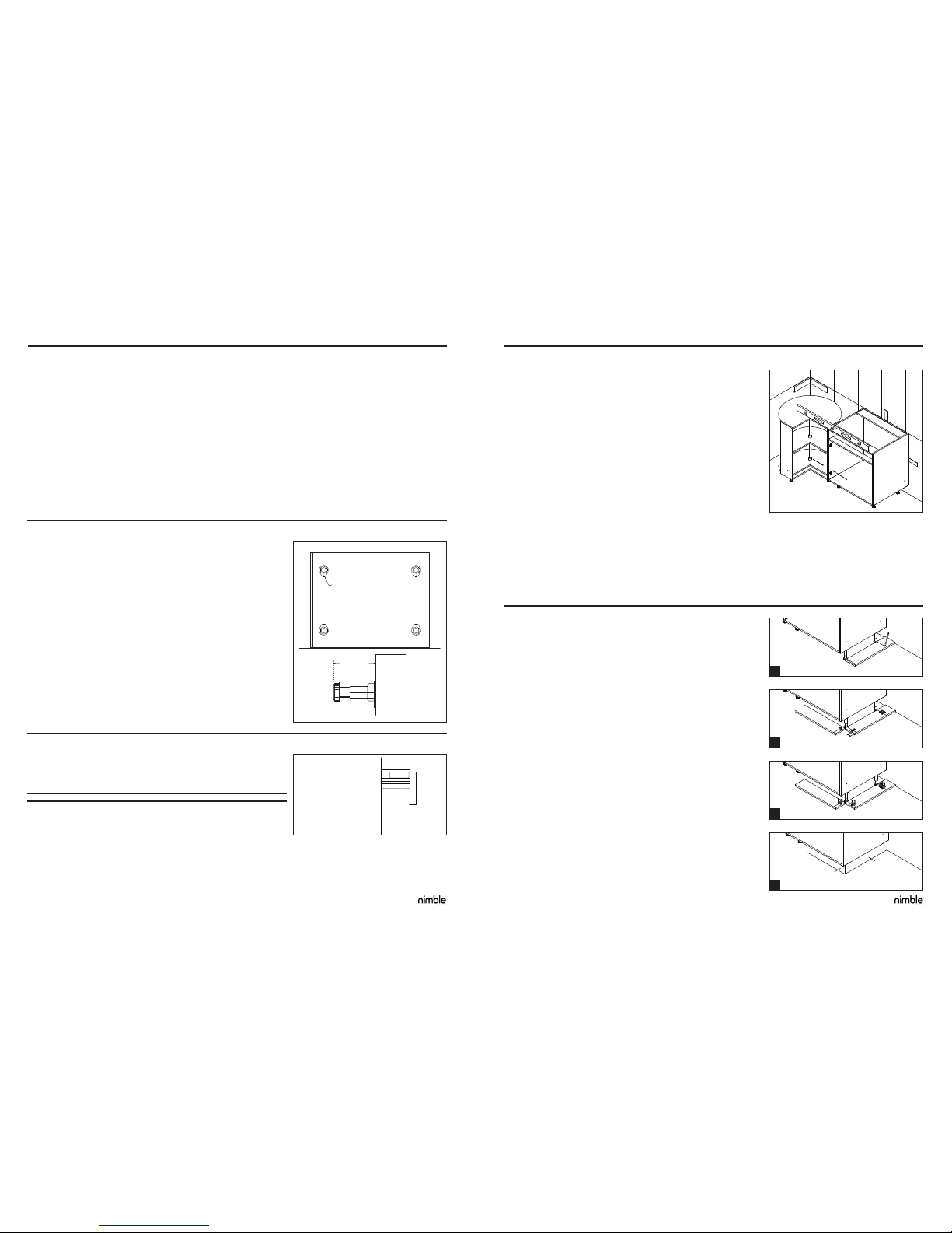
STEP 6: Base Box Installation Preparation
NOTE: If installing wall boxes, all wall boxes should be installed prior to installation
of the base boxes.
6a First remove drawer(s) from the box. See Step 7.
6b Gently lay the base box on its back.
6c With the supplied adjustable legs (CC), insert the dowel on the top of the leg
into the 4 pre-drilled holes on the bottom of the box.
6d Verify the legs are pushed in ush with the box bottom.
6e Take the supplied #6 x 5/8 in. screws (FF) - 4 screws per leg - and fasten the
legs to the bottom of the box.
6f Verify the tab on the legs is positioned as shown in the diagram and over the
small alignment holes.
6g Adjust the legs so they are 5 in. in length from the bottom of the box by rotating
the bottom of the leg clockwise to lengthen and counterclockwise to shorten.
This will save time when leveling the boxes later.
6h By setting the legs at 5 in., your boxes will be 35 in. tall and line up with your
previously marked reference line on the wall.
NOTE: Carefully pick the box up from the bottom and place in position. NEVER
drag the cabinet box across the oor.
STEP 7: Base Drawer Box Removal
7a Remove drawer boxes by fully opening the drawer and lifting up on the box
until it releases from the glides.
7b Proceed to Step 8.
STEP 9: Base Drawer Box Installation
9a Install the drawer boxes by placing the drawer box on the guide rails and rmly
pushing the drawer straight back into the box.
9b The drawer will click on to the guide rails and be secured. Test by opening and
closing the drawer.
STEP 8: Base Box Installation
8a Start installing the base boxes in the corner of the design. (See Corner Base
Box Installation Instructions)
8b Make sure the box faces align both horizontally and vertically.
8c With the provided connecting bolts and nuts (AA), fasten the two boxes
together through the 4 pre-drilled holes located on each end of the box.
8d Verify the boxes are level and square. Adjust the legs if the boxes are not level
by turning the bottom of the leg clockwise to lengthen the leg and counter-
clockwise to shorten the leg.
8e Verify the box legs are rm against the oor to evenly distribute the weight of
the box. Failure to do so may result in damage to the boxes.
8f Drill through the base box back where the support rail is located and into the
pre-located studs with a 3/32 in. diameter drill bit, approximately 2 in. deep.
8g Holes should come no closer than 2 in. to any inside vertical edge of the box
and no further than 3.5 in. from the top edge of the box.
8h Insert the #10 x 2 ½ in. Washer-Head Cabinet Box Installation Screws into the
predrilled holes until they are nearly tight.
8i Verify the back is fully supported, shimmed as needed, and does not bow into
any imperfections in the wall.
8j Check to ensure the box is level in all directions and adjust as needed.
8k Fully tighten the screws and recheck for level and square.
8l Repeat to install the rest of your base boxes.
8m Proceed to Step 9
STEP 10: Toekick Installation
10a Install the toekick (sold separately) after all base boxes are installed. Begin by
laying your toekick face down against the Adjustable Legs (CC).
10b Mark and cut the toekick to the correct length. For the end of boxes returning to
the wall, cut the board to 20 7/8 inches.
10c Take your pen/pencil and straight edge and mark the center of the Adjustable
Legs (CC) as shown in Image 1.
10d Attach the included Toekick Attachment Plates (EE) to the toekick with the
provided #6 x 5/8 in. at head Phillips screws (FF). The highest Attachment
Plate (EE) should be 1-1/2 in. from the top of the toekick as shown in Image 2.
Use two Attachment Plates (EE) on each end return board. Use two Attachment
Plates (EE) per cabinet for the front board.
NOTE: If there will be two toekick boards meeting at a right angle (as when
installed on the front and side of a cabinet) remember to offset the mounting heights
of the toe kick plates so they do not interfere with one another.
10e Slide the provided Toekick Clips (DD) into the Toekick Attachment Plates (EE)
so the toekick is ready to be secured to the Adjustable Legs (CC). Image 3.
10f Install the toekick to the Adjustable Legs (CC) by pushing the Toekick with the
Toekick Attachment Plates (EE) onto the Adjustable Legs (CC) of the cabinet as
shown in Image 4 until all of the Toekicks are installed.
INSTALLATION INSTRUCTIONS INSTALLATION INSTRUCTIONS
Installation Videos at: benimble.com Installation Videos at: benimble.com
1
2
3
4
Page 4

7
800114
6
CARE AND MAINTENANCE
800114
ARMOIRE MURALE
(A) Armoire murale (x1)
(B) Étagères ajustables (La quantité varie selon la taille de l’armoire)
(AA) Écrous d’assemblage et Vis d’assemblage (x4)
(BB) Supports d’étagère (La quantité varie selon la taille de l’armoire)
ARMOIRE DE PLANCHER
(A) Armoire de plancher (x1)
(B) Étagères ajustables (La quantité varie selon la taille de l’armoire)
(AA) Écrous d’assemblage et Vis d’assemblage (x4)
(BB) Supports d’étagère (La quantité varie selon la taille de l’armoire)
(CC) Pieds ajustables (x4)
(DD) Attache du coup de pied (x4)
(EE) Plaque de xation du coup de pied (x4)
(FF) Vis (à tête plate Phillips Type A #6 x 5/8 p.)
AA
BB
CC DD EE FF
INSTALLATION DES ARMOIRES MURALES
ET DE PLANCHER
Des questions ?
Contactez le service à la clientèle au 1-800-465-4003, du lundi au vendredi de 8 h à 18 h (HNE), et le samedi de 9 h
à 13 h (HNE).
B
BA A
Information sur la sécurité
Veuillez lire et bien comprendre l’intégralité de ce manuel avant de commencer l’assemblage, l’opération ou l’installation du produit.
CONTENU DU PAQUET
Remarque : la quincaillerie n’est pas à la taille réelle. Le dessin au trait n’est qu’une représentation; l’apparence du produit
acheté peut varier.
Use non-abrasive cleaners and/or cleaning agents that do not contain solvents.
The following is a general summary of what the full Limited Warranty includes, excludes and other important limitations and disclaimers. For a
full statement of the Limited Warranty, including all exclusions, limitations and disclaimers, call 1-844-614-0002.
The Product is warranted to be free from non-conformities in material and workmanship under normal use, from the date of purchase and for
as long as the original consumer purchaser owns and lives in the home in which the Product is rst installed. This Limited Warranty is only
for residential use in the United States, Canada or Mexico and ends when the original consumer purchaser transfers ownership or ceases to
occupy the home. If the event of a non-conformity in material or workmanship during this period, Seller will, free of charge, repair or replace
the Product at its sole discretion. As an example, the Limited Warranty does not cover damage or failure caused by abuse, misuse, vandalism,
negligence, or accident, ordinary wear or tear, improper installation, improper cleaning or maintenance (such as use of abrasive cleaners,
cleaners that contain chlorine, scufng sponges, or steel wool), environmental conditions that affect the color or appearance of the Product
over time (such as sunlight, smoke, extreme temperature or humidity, other atmospheric conditions), re, ood, or Acts of God. The Limited
Warranty does NOT cover any indirect or consequential damages resulting from non-conformity, nor labor charges for installation or removal,
nor freight charges to return Product if required by Seller; in no event will Seller’s liability exceed the purchase price of the Product. TO THE
EXTENT PERMITTED BY LAW, ALL OTHER IMPLIED OR EXPRESS WARRANTIES ARE DISCLAIMED, INCLUDING ALL WARRANTIES
OF MERCHANTABILITY AND/OR FITNESS FOR A PARTICULAR PURPOSE. The Limited Warranty gives the purchaser specic legal rights,
but the purchaser may also have other rights which vary from state to state or province/territory to province/territory. Further information is also
available by calling Customer Service at 1-844-614-0002.
LIMITED WARRANTY
Printed in USA
nimble is a registered trademark
MasterBrand Cabinets, Inc. All Rights Reserved.
Installation Videos at: benimble.com Installation Videos at: benimble.com
Coup de pied vendu séparément
Page 5

8
INSTRUCTIONS D’INSTALLATION
INSTRUCTIONS D’INSTALLATION
PRÉPARATION
Avant de commencer l’assemblage du produit, assurez-vous d’avoir toutes les pièces en les comparant à la liste de contenu du paquet.
Si une pièce est manquante ou endommagée, n’essayez pas d’installer le produit.
Outils nécessaires à l’installation (non inclus) : Vis avec tête de rondelle de 10 x 2 ½ p. pour l’installation de l’armoire, un tournevis
Phillips, une perceuse, une mèche de 3/32 p., un stylo ou crayon mine, un niveau, un mètre à mesurer, un localisateur de montants, une
règle droite, une scie et des cales. Des vis à bois à tête conique de 1 p. seront peut-être nécessaires, selon l’aménagement de la pièce.
9
Plumb Line
Use level to draw line
Mark top
line for wall,
tall cabinets
Level
Straight edge
High Point
Corner is out
of square
Corner is out
of plumb
(not vertical)
Floor not level
Shim As Necessary
Utilisez des cales si nécessaire.
Puede colocar cuñas según
se requiera.
Shim
ÉTAPE 3 – Installation de l’armoire murale
3a Commencez par installer l’armoire murale d’angle dans l’angle de la pièce.
3b Si vous utilisez les rails de guidage d’installation, accrochez l’armoire sur le rail
de guidage à l’aide de la partie entaillée à l’arrière de l’armoire.
3c Mesurez à partir de l’angle du mur jusqu’aux montants muraux et transférez les
marques à l’intérieur de l’armoire.
3d Forez à travers l’arrière de l’armoire à l’endroit où les rails de support sont
situés et dans les montants prédéterminés en utilisant la mèche de 3/32 p. de
diamètre, à une profondeur approximative de 2 p. Les trous ne devraient pas
être forés à moins de 2 p. des bords intérieurs de l’armoire.
3e Insérez les vis à tête de rondelle de 10 x 2 ½ p. (non incluses) dans les trous
jusqu’à ce qu’elles soient presque serrées au maximum.
3f Ne serrez pas complètement les vis avant d’avoir terminé la mise à niveau
nale et le calage.
3g Vériez le devant, les côtés et les dessous de toutes les armoires avec un
niveau. Une fois que l’armoire est à niveau et d’équerre, serrez complètement
les vis à tête de rondelle d’installation des armoires de 10 x 2 ½ p.
3h Installez les étagères ajustables (B) à l’aide des chevilles (BB).
ATTENTION : N’utilisez jamais de clous pour monter les armoires. L’utilisation de clous annulera votre garantie d’usine,
écrite ou implicite. Les murs en ciment, en béton, en briques ou en carrelage exigent des vis d’ancrage ou des boulons
à ailettes.
ÉTAPE 4 – Installation des armoires adjacentes
4a Continuez l’installation de vos armoires murales en plaçant l’armoire adjacente
sur le rail de guidage. Veillez à aligner les bords horizontaux inférieurs.
4b Grâce aux boulons (BB) et aux écrous (CC) de raccordement, attachez les
deux armoires ensemble en utilisant les 4 trous préforés situés à chaque
extrémité de l’armoire.
4c En fonction de la conguration de votre cuisine, il peut être nécessaire
d’attacher certaines armoires ensemble avec des vis à bois à tête conique
standard de 1 p. (non incluses).
4d Calez l’armoire, si nécessaire, pour la mettre à niveau.
4e Attachez l’armoire au mur, conformément aux étapes 3d à 3h détaillées
précédemment.
4f Continuez l’installation du reste de vos armoires murales en procédant de la
même façon.
Remarque : Si vous installez une seule armoire murale, suivez les instructions montrées à l’étape 5 pour une
installation correcte.
ÉTAPE 5 – Installation d’une seule armoire murale
5a Suivez les étapes 1 à 3 an de préparer le mur à l’installation de votre armoire.
5b L’armoire devrait être placée de telle façon à ce que les montants muraux
sur lesquels vous comptez l’attacher ne soient pas à moins de 2 p. des bords
intérieurs verticaux.
5c Assurez-vous que l’armoire est à niveau et d’équerre.
5d Utilisez des cales pour remplir les zones irrégulières entre le mur et l’arrière de
l’armoire. L’omission de cette étape pourrait endommager l’armoire.
5e Faites attention aux endroits où vous prévoyez visser les armoires au mur an
de veiller à ce qu’il n’y ait pas d’espaces vides entre l’armoire et le mur.
5f Forez à travers l’arrière de l’armoire dans le(s) montant(s) prédéterminé(s) à
l’aide d’une mèche de 3/32 p. de diamètre, à une profondeur de 2 p. et à au
moins 4 endroits.
5g Les trous ne devraient pas être situés à moins de 2 p. et à plus de 12 p.
des bords intérieurs verticaux et 2 p. de l’intérieur du haut et du bas (voir
illustration).
5h Les trous devraient également être situés en haut et en bas de l’arrière de
l’armoire. Il est nécessaire d’utiliser des vis à tête de rondelle de 10 x 2 ½ p.
(non incluses) pour l’installation de l’armoire.
ÉTAPE 1 – Préparation pour l’installation de l’armoire
1a Enlevez les plinthes et les autres objets présents sur la surface murale où
les armoires doivent être installées. À l’aide d’une règle droite et d’un niveau,
trouvez le point culminant du plancher où les armoires doivent être installées.
1b À partir du point culminant, tracez une ligne horizontale sur chaque mur où les
armoires seront xées 1 .
1c Tracez une autre ligne 35 p. au-dessus de la première ligne 2 .
1d À partir de ces lignes, tracez une autre ligne horizontale à 54 p. de hauteur pour
le bas des armoires murales 3 ou à 77-3/4 p. de hauteur 4 si vous utilisez le
rail de guidage d’installation facultatif pour les armoires murales et à 84 p. de
hauteur 5 pour les hauteurs des armoires utilitaires.
1e Localisez les montants muraux avec un localisateur de montants et marquez
ceux sur lesquels les armoires seront xées. Installez toujours les armoires sur
des montants muraux.
1f Mesurez encore une fois l’endroit pour vérier que vos armoires iront bien à cet emplacement.
1g Enlevez les étagères ajustables (B) des armoires avant l’installation.
REMARQUE : Avant de quitter l’usine de fabrication, toutes les armoires sont soumises à des inspections de qualité. Des dommages
peuvent survenir lors de la manutention entre l’usine de fabrication et la destination nale. Inspectez chaque armoire avec soin. Si vous
constatez un dommage quelconque, replacez l’armoire à l’intérieur du carton et avisez votre détaillant.
ÉTAPE 2 – Rail de guidage d’installation (facultatif)
2a Mesurez la longueur de l’ensemble de vos armoires murales. Ensuite, coupez
le rail de guidage à une longueur de 1 à 2 pouces plus courte an que le rail ne
dépasse pas les armoires. Si vous installez une armoire murale d’angle, vériez
que le rail de guidage soit à une distance de 6 pouces de l’angle an de laisser
sufsamment d’espace, dans le cas où votre mur n’est pas d’équerre.
2b Marquez le centre du rail de guidage et utilisez la ligne tracée à 77-3/4 p. 4 pour
monter le rail de guidage des armoires murales. Placez la petite surface du rail de
guidage contre le mur, comme le montre l’image.
2c Préforez à travers le rail de guidage dans les montants muraux avec la mèche de
3/32 p. jusqu’à une profondeur d’environ 2 p.
2d Fixez le rail de guidage d’installation au mur avec les vis à tête de rondelle de 10
x 2 ½ p. (non incluses) tout en vous assurant que le rail de guidage est à niveau.
Posez des cales, si nécessaire, pour garder le rail de guidage à niveau et à plomb.
REMARQUE : Le rail de guidage d’installation facilite l’installation. Chaque armoire doit quand même être vissée individuellement
au mur. Les armoires utilitaires n’utilisent pas de rail de guidage. Assurez-vous que le rail de guidage d’installation n’est pas monté au
mur là où une armoire utilitaire doit être placée.
Shim
Shim
12”
max
2”
min
2”
min
Installation Videos at: benimble.com Installation Videos at: benimble.com
5
4
3
2
1
MISE EN GARDE SUR LA POUSSIÈRE DE BOIS!
LE SCIAGE, LE PONÇAGE ET L’USINAGE DES PRODUITS DU BOIS PEUVENT PRODUIRE DE LA POUSSIÈRE DE BOIS SUSCEPTIBLE DE POSER UN RISQUE D’INCENDIE ET D’EXPLOSION.
AVERTISSEMENT:Lesmodicationsapportéesàceproduitpeuventdégagerdelapoussièredebois,unesubstancequel’ÉtatdeCaliforniereconnaîtcommeétantcancérigène.
La poussière de bois peut provoquer une irritation des poumons, des voies respiratoires supérieures, des yeux et de la peau. Le Centre International de Recherche sur le
Cancer (CIRC) a classé la poussière de bois comme une substance pouvant causer le cancer nasal chez les humains.
•Tenirlapoussièreàl’écartdetoutesourced’inammation Premiers soins:
•Évitertouteinhalationprolongéeourépétéedelapoussièredebois
présente dans l’air
En cas d’inhalation, sortir à l’air libre. En cas de contact avec les yeux ou la peau, rincer
•Évitertoutcontactdelapoussièreaveclesyeuxetlapeau
abondamment à l’eau. Si l’irritation persiste, consulter un médecin.
POUR OBTENIR LA FICHE SIGNALÉTIQUE DE LA POUSSIÈRE DE BOIS, COMMUNIQUER AVEC www.masterbrand.com/regulatoryinformation
Page 6

11
10
5 inches
TAB
Drawer Box
Release
1 1/2 IN.
20
7
/
8
in.
1 1/2 IN.
1 1/2 IN.
20
7
/
8
in.
1 1/2 IN.
ÉTAPE 5 – Installation d’une seule armoire murale (cont’d)
5i Les murs en ciment, en béton, en briques ou en carrelage exigent des vis d’ancrage (non incluses).
5j Insérez les vis à tête de rondelle d’installation d’armoire de 10 x 2 ½ p. (non incluses) dans les
trous jusqu’à ce qu’elles soient presque complètement serrées. Assurez-vous que l’arrière est bien
soutenu par des cales, si nécessaire, et qu’il n’est pas courbé par des imperfections du mur.
5k Vériez que l’armoire soit à niveau et à plomb. Ajustez si nécessaire.
5l Serrez complètement les vis et installez les étagères ajustables (B).
REMARQUE : Le rail de guidage d’installation facilite l’installation. Chaque armoire doit quand même
être vissée individuellement au mur.
IMPORTANT : Les modications structurales apportées à une armoire murale peuvent l’affaiblir
considérablement. C’est la raison pour laquelle les modications telles que la découpe de l’arrière de
l’armoire pour contourner une obstruction murale sont déconseillées. Si une obstruction est présente,
nous vous suggérons d’utiliser une (des) armoire(s) qui ne nécessite(nt) aucune modication. Si une
modication est nécessaire, la garantie de l’armoire sera annulée et il incombera à l’installateur de
prendre les mesures appropriées pour compenser toute perte de solidité ou de support résultant de la
modication.
ÉTAPE 6 – Préparation à l’installation de l’armoire de plancher
REMARQUE : Si vous installez des armoires murales, toutes les armoires murales
devraient être installées avant l’installation des armoires de plancher.
6a Retirez d’abord le(s) tiroir(s) de l’armoire. Voir l’étape 7.
6b Déposez doucement l’armoire de plancher sur son côté arrière.
6c À l’aide des pieds ajustables fournis (CC), insérez le goujon du dessus du pied
dans les 4 trous préforés dans le dessous de l’armoire.
6d Vériez que les pieds soient poussés de telle manière à ce qu’ils afeurent
parfaitement avec le dessous de l’armoire.
6e Prenez les vis fournies #6 x 5/8 p. (FF) - 4 vis par pied – et attachez les pieds
au dessous de l’armoire.
6f Vériez que la languette des pieds soit positionnée comme le montre le
diagramme et qu’elle couvre bien les petits trous d’alignement.
6g Ajustez les pieds an qu’ils mesurent 5 p. de longueur à partir du dessous de
l’armoire en faisant tourner le bas du pied dans le sens des aiguilles d’une
montre pour l’allonger et dans le sens inverse pour le raccourcir. Ceci vous
gagnera du temps lorsque vous mettrez les armoires à niveau plus tard.
6h En mettant les pieds à 5 p. de longueur, vos armoires seront d’une hauteur de
35 p. et s’aligneront à la ligne de référence tracée précédemment sur le mur.
REMARQUE : Soulevez doucement l’armoire à partir du bas et placez-la en
position. Ne tirez JAMAIS l’armoire à travers le plancher.
ÉTAPE 7: Retrait d’une armoire de plancher à tiroir
7a Enlevez les tiroirs en les tirant jusqu’au bout et en les soulevant de l’armoire
jusqu’à ce qu’ils se détachent des glissières.
7b Passez à l’étape 8.
STEP 9: Installation d’une armoire de plancher à tiroir
9a Installez les tiroirs en les plaçant sur les glissières et en les repoussant fermement dans l’armoire.
9b Le tiroir s’enclenchera sur la glissière et sera sécurisé. Testez en ouvrant et en refermant le tiroir.
ÉTAPE 8 – Installation d’une armoire de plancher
8a Commencez par installer les armoires de plancher à l’angle de l’aménagement.
(Voir les instructions pour l’installation d’une armoire d’angle de plancher)
8b Assurez-vous que les faces de l’armoire sont alignées horizontalement et
verticalement.
8c Grâce aux boulons (BB) et aux écrous (CC) de raccordement, attachez les
deux armoires ensemble en utilisant les 4 trous préforés situés à chaque
extrémité de l’armoire.
8d Vériez que les armoires soient à niveau et d’équerre. Ajustez les armoires
qui ne sont pas à niveau en tournant le bas du pied dans le sens des aiguilles
d’une montre pour allonger le pied et dans le sens inverse pour le raccourcir.
8e Vériez que les pieds de l’armoire soient bien placés fermement sur le plancher
an de répartir le poids de l’armoire de façon régulière. L’omission de cette
étape pourrait endommager les armoires.
8f Forez à travers l’arrière de l’armoire de plancher là où le rail de soutien est situé
et dans les montants muraux prédéterminés grâce à une mèche de 3/32 p. de
diamètre, à une profondeur d’environ 2 p.
8g Les trous ne devraient pas être situés à moins de 2 p. des bords intérieurs verticaux de l’armoire et à plus de 3,5 p. du bord
supérieur de l’armoire.
8h Insérez les vis à tête de rondelle d’installation d’armoire 10 x 2 ½ p. dans les trous préforés jusqu’à ce qu’elles soient presque
complètement serrées.
8i Vériez que l’arrière soit bien soutenu, calé si nécessaire, et qu’il ne soit pas courbé en raison d’une imperfection murale.
8j Vériez que l’armoire soit à niveau dans toutes les directions et ajustez si nécessaire.
8k Serrez complètement les vis et vériez une nouvelle fois que l’armoire soit à niveau et d’équerre.
8l Répétez cette étape pour installer le reste de vos armoires de plancher.
8m Passez à l’étape 9.
Étape 10 : Installation du coup de pied
*Coup de pied vendu séparément
10a Installez le coup de pied (vendu séparément) une fois que toutes les
armoires de plancher sont installées. Commencez par placer le devant du
coup de pied contre les pieds ajustables (CC).
10b Marquez et coupez le coup de pied à la longueur nécessaire. Pour les côtés
des armoires retournant vers le mur, coupez la bande du coup de pied à une
longueur de 20 7/8 pouces.
10c Avec votre stylo/crayon à mine, faites un trait droit et marquez le centre des
pieds ajustables (CC), comme le montre l’image 1.
10d Attachez les plaques de xation du coup de pied fournies (EE) au coup de
pied à l’aide des vis à tête plate Phillips #6 x 5/8 p. fournies (FF). L’attache la
plus haute devrait être à 1-1/2 p. du haut du coup de pied, comme le montre
l’image 2. Utilisez deux attaches à chaque bande de retour. Utilisez deux
attaches par armoire pour la bande de devant.
REMARQUE : Si deux bandes de coup de pied se rencontrent à un angle droit
(celles qui sont installées sur le devant et sur le côté d’une armoire), rappelezvous de compenser les hauteurs de xation des plaques du coup de pied an
qu’elles n’interfèrent pas l’une avec l’autre.
10e Glissez les attaches fournies du coup de pied (DD) dans les plaques de
xation du coup de pied (EE) an que le coup de pied soit sécurisé aux
pieds ajustables (CC). Image 3.
10f Installez le coup de pied aux pieds ajustables (CC) en poussant le coup
de pied et les plaques de xation (EE) sur les pieds ajustables (CC) de
l’armoire, comme le montre l’image 4, jusqu’à ce que tous les coups de pied
soient installés.
INSTRUCTIONS D’INSTALLATION INSTRUCTIONS D’INSTALLATION
Installation Videos at: benimble.com Installation Videos at: benimble.com
1
2
3
4
Page 7

13
800114
12
SOIN ET ENTRETIEN
800114
MARCO DE GABINETE DE PARED
(A) Marcos de gabinetes (x1)
(B) Estantes ajustables (La cantidad varía según el tamaño de la caja)
(AA) Pernos de conexión y Tuercas de conexión (x4)
(BB) Pasadores para estantes (La cantidad varía según la cantidad
de estantes)
MARCO DE GABINETE INFERIOR
(A) Marco de gabinete inferior (x1)
(B) Estantes ajustables (La cantidad varía según el tamaño de la caja)
(AA) Pernos de conexión y Tuercas de conexión (x4)
(BB) Pasadores para estantes (La cantidad varía según la
cantidad de estantes)
(CC) Patas ajustables (x4)
(DD) Grapa para rodapié (x4)
(EE) Placa de jación del rodapié (x4)
(FF) Tornillos (#6 x 5/8” de cabeza plana Phillips, Tipo A)
AA
BB
CC DD EE FF
INSTALACIÓN DE LOS MARCOS DE
GABINETE INFERIORES Y DE PARED
¿Preguntas?
Llame a Servicio al cliente al 1-844-614-0002, de lunes a viernes de 8:00 a.m. a 6:00 p.m., hora del este y los
sábados de 9:00 a.m. a 1:00 p.m. hora del este.
B
BA A
Información de seguridad
Por favor, lea y comprenda completamente este manual antes de intentar ensamblar, usar o instalar el producto.
CONTENIDO DEL PAQUETE
NOTA: la quincallería no está ilustrada en tamaño real. El dibujo lineal constituye solamente una representación. El producto
comprado puede variar en apariencia.
Utilisez des nettoyants et/ou produits de nettoyage non abrasifs qui ne contiennent pas de solvants.
La partie suivante est un résumé général de ce que la garantie limitée inclut et exclut, et d’autres limitations et exonérations importantes. Pour
obtenir l’énoncé complet de la garantie limitée, y compris tous les exclusions, limitations et exonérations, veuillez appeler le 1-800-465-4003.
Le Produit est garanti exempt de tout défaut de conformité, tant dans les matériaux utilisés que dans la fabrication, dans des conditions
d’utilisation normale, depuis la date d’achat et aussi longtemps que l’acheteur original est propriétaire et réside dans l’habitation dans laquelle
le Produit a été installé à l’origine. Cette garantie limitée s’applique uniquement à l’utilisation résidentielle aux États-Unis, au Canada et
au Mexique, et se termine lorsque l’acheteur original transfère la propriété ou cesse d’occuper l’habitation. Dans l’éventualité d’une nonconformité des matériaux ou de la fabrication pendant cette période, le Vendeur réparera ou remplacera gratuitement le Produit, à sa seule
discrétion. Par exemple, la garantie limitée ne couvre pas les dommages ou les défaillances causés par la mauvaise utilisation, le vandalisme,
la négligence ou un accident, l’usure normale, une mauvaise installation, un mauvais nettoyage ou entretien (en cas d’utilisation de nettoyants
abrasifs, de nettoyants contenant du chlore, d’éponges abrasives ou de laine de verre), des conditions environnementales qui affectent
la couleur ou l’apparence du Produit avec le temps (comme la lumière du soleil, la fumée, la température ou l’humidité extrême, autres
conditions atmosphériques), le feu, l’inondation ou les catastrophes naturelles. La garantie limitée ne couvre pas les dommages indirects ou
consécutifs résultant d’une non-conformité, ni les frais de main-d’œuvre pour l’installation ou le retrait, les frais d’expédition pour retourner le
Produit s’ils sont exigés du Vendeur; la responsabilité du Vendeur ne dépassera en aucun cas le prix d’achat du Produit. DANS LES LIMITES
AUTORISÉES PAR LA LOI, TOUTES LES AUTRES GARANTIES IMPLICITES OU EXPRESSES SONT REJETÉES, Y COMPRIS TOUTES
LES GARANTIES DE COMMERCIALISATION ET/OU D’APTITUDE À UN USAGE PARTICULIER. La garantie limitée donne à l’acheteur
des droits juridiques spéciques, mais l’acheteur peut aussi faire valoir d’autres droits qui varient en fonction de l’état, de la province ou du
territoire. Pour davantage d’information, veuillez contacter le service à la clientèle au 1-800-465-4003.
GARANTIE LIMITÉE
Imprimé aux É.-U.
Nimble est une marque déposée.
MasterBrand Cabinets, Inc. Tous droits réservés.
Installation Videos at: benimble.com Installation Videos at: benimble.com
Los rodapiés se venden por separado
Page 8

14
INSTRUCCIONES PARA LA INSTALACIÓN
INSTRUCCIONES PARA LA INSTALACIÓN
PREPARACIÓN
Antes de comenzar a ensamblar el producto, cerciórese de que todas las partes estén presentes, vericándolas con la lista del contenido
del paquete. Si alguna parte faltase o esté dañada, no intente instalar el producto.
Herramientas necesarias para la instalación (no incluidas): tornillos con cabeza de arandela #10 x 2 ½” para instalar los marcos de
gabinetes, destornillador Phillips, taladro, broca de 3/32”, lápiz o bolígrafo, nivel de carpintero, cinta métrica, detector de vigas, regla plana,
sierra y calzos. Es posible que necesite tornillos de cabeza cónica para madera de 1”, en dependencia de las características de la habitación.
15
Plumb Line
Use level to draw line
Mark top
line for wall,
tall cabinets
Level
Straight edge
High Point
Corner is out
of square
Corner is out
of plumb
(not vertical)
Floor not level
Shim As Necessary
Utilisez des cales si nécessaire.
Puede colocar cuñas según
se requiera.
Shim
PASO 3 - Instalación de los marcos de pared
3a Comience colgando el marco esquinero en la esquina de la habitación.
3b Si está utilizando rieles guías, enganche el marco del gabinete sobre el riel guía,
mediante la hendidura que se encuentra detrás del marco del gabinete.
3c Mida desde la esquina de la pared hasta la marca de los montantes de la pared y
traspase o copie estas marcas en el interior del marco.
3d Perfore con una broca de 3/32” de diámetro el marco del gabinete, donde en la
parte de atrás se encuentran las barras de apoyo y a través de los montantes
de pared previamente localizados, a aproximadamente 2” de profundidad. No se
deben perforar agujeros de menos de 2” de distancia, contando desde cualquier
borde interior del marco.
3e Introduzca los tornillos de cabeza de arandela de #10 x 2 ½” para instalar los
marcos de gabinetes (no incluidos) en los agujeros hasta que queden ajustados.
3f Apriete los tornillos solamente cuando termine de nivelar y calzar completamente.
3g Compruebe los frontales, laterales y parte inferior de todos los marcos de pared con un nivel. Cuando el marco esté nivelado y
escuadrado, apriete completamente los tornillos de cabeza de arandela de 10 x 2 ½” para instalar los marcos de gabinetes.
3h Instale los estantes ajustables (B) utilizando los pasadores para estantes proporcionados (BB).
PRECAUCIONES: Nunca use clavos para montar los marcos. Al utilizar clavos se anulará la garantía de fábrica, escrita o implícita.
Las paredes de cemento, bloques, ladrillos o azulejos requieren anclajes de pared para tornillos o pernos de palanca.
PASO 4 – Instalación de los marcos de pared adyacentes
4a Continúe instalando los marcos de pared, colocando el siguiente marco en el
riel guía. Tenga cuidado de alinear los bordes horizontales inferiores.
4b Con los pernos de conexión (BB) y las tuercas (CC) provistos, apriete los dos
cuadros juntos a través de los 4 agujeros previamente perforados ubicados en
el extremo de cada marco.
4c Dependiendo de la conguración de su cocina, podría necesitar tornillos de
cabeza cónica para madera de 1” (no incluidos) para jar algunos marcos.
4d Calce los marcos, si necesario, para nivelarlos.
4e Fije el marco a la pared como mencionado previamente en el paso 3d-3h.
4f Continúe instalando el resto de los marcos de la misma manera.
NOTA: Si va a instalar un marco de pared simple, siga las instrucciones que se muestran en el paso 5 para su correcta instalación.
PASO 5 - Instalación de un marco de pared simple
5a Siga los pasos de 1 a 3 para preparar la pared para su marco de gabinete.
5b El marco del gabinete debe estar ubicado de manera que los montantes en los
que planea jar el marco estén ubicados a 2” mínimo, a partir de los bordes
verticales interiores del marco.
5c Compruebe que el marco está nivelado y escuadrado.
5d Calce para llenar áreas irregulares entre la pared y la parte posterior del marco.
El no cumplir esta medida podría causarle daños al marco del gabinete.
5e Preste especial atención a los lugares donde va a atornillar los marcos a la
pared, para asegurarse de que no hayan espacios vacíos entre ambos.
5f Perfore con una broca de 3/32” de diámetro el marco del gabinete directamente
hacia la parte de atrás donde se encuentran los montantes de pared
previamente localizados, a aproximadamente 2” de profundidad y en 4 lugares
diferentes como mínimo.
5g Los agujeros deberán encontrarse a no menos de 2” y no más de 12” de
cualquier borde vertical interior hacia afuera y a 2” contando desde la parte
interior hacia arriba y hacia abajo. (Ver ilustración)
5h Los agujeros también deben estar ubicados en la parte superior e inferior de la
parte posterior del marco del gabinete. Necesitará utilizar los tornillos de cabeza
de arandela de 10 x 2 ½ “ para instalar los marcos de gabinetes (no incluidos).
PASO 1 - Preparar la instalación de los marcos de gabinetes
1a Retire las tablas de base u otros objetos del área de la pared donde se van
a instalar los marcos de los gabinetes. Con una regla y un nivel encuentre el
punto más alto en el suelo donde se van a instalar los marcos.
1b Desde el punto más alto, dibuje una línea horizontal nivelada en cada pared en
la que se instalarán los marcos de los gabinetes. 1 .
1c Dibuje otra línea de 35” a partir de la primera línea 2 .
1d A partir de estas líneas dibuje otra línea horizontal para arriba de 54”, 3 para el
fondo de los marcos de pared o una de 77-3/4” para arriba 4 si está utilizando
la Guía opcional para instalar rieles para los marcos de pared y 84” para arriba
5
para la altura de las cajas falsas.
1e Busque montantes en la pared con un detector de vigas y marque en los que se
vayan a instalar los marcos. Siempre instale los marcos en los montantes de la
pared.
1f Vuelva a medir el área para conrmar que sus marcos cabrán en el espacio.
1g Retire los estantes ajustables (B) de los marcos antes de la instalación.
NOTA: Todas los marcos están sometidos a controles de calidad antes de salir de la fábrica. En ocasiones se puedven dañar durante
su manejo entre la fábrica y el destino nal. Inspeccione cada marco con cuidado. Si encuentra un daño, coloque el marco en su caja e
infórmele de esto a su vendedor..
PASO 2 - Instalación del riel guía (Opcional)
2a Determine la longitud total de los marcos de las gabinetes de pared. Luego corte
el riel guía a una longitud de 1 a 2” más corto, de modo que el riel guía no se
extienda más allá de los marcos de las cajas. Si va a instalar un marco de pared
esquinero, mantenga el riel guía a 6” de la esquina de la pared hacia afuera, para
tener exibilidad en la instalación, en caso de que su pared no esté a escuadra.
2b Marque el centro del riel guía y sírvase de la línea trazada previamente de 77-3
/ 4” 4 para instalar el riel guía para los marcos de gabinetes de pared. Coloque
contra la pared la pequeña supercie del riel guía que va a instalar, como lo
muestra la imagen.
2c Taladre previamente agujeros de aproximadamente 2 pulgas de profundidad en el
riel guía que va a instalar en los montantes de pared con la broca de 3/32”.
2d Atornille el riel guía para la instalación en la pared con los tornillos de cabeza de arandela #10 x 2 ½” para instalar los marcos
de gabinetes (no incluidos), asegurándose de que el riel guía esté nivelado. Coloque cuñas donde se requiera y plome, para
mantener nivelado el riel guía.
NOTA: El riel guía es una ayuda para la instalación de cada marco de gabinete. Cada uno de los marcos de gabinete debe estar
atornillado también a la pared. Para las cajas falsas no se necesita riel guía. Compruebe que el riel guía de instalación no está
montado en la pared, en el lugar en el que las cajas falsas serán instaladas.
Shim
Shim
12”
max
2”
min
2”
min
Installation Videos at: benimble.com Installation Videos at: benimble.com
5
4
3
2
1
POLVO DE MADERA. ¡PRECAUCIÓN!
AL ASERRAR, LIJAR O TORNEAR PRODUCTOS DE MADERA SE PUEDE PRODUCIR POLVO DE MADERA QUE PUEDE CREAR PELIGRO DE INCENDIO O EXPLOSIÓN.
ADVERTENCIA:Lamodicacióndeesteproductopuedeliberarpolvodemadera,unasustanciaconocidaenelEstadodeCaliforniacomocancerígena.
El polvo de madera puede causar irritación en los pulmones, las vías respiratorias superiores, los ojos y la piel. Algunas especies de madera pueden causar dermatitis y/o
efectos alérgicos respiratorios. La Agencia Internacional de Investigación sobre el Cáncer (IARC) ha clasicado el polvo de madera como un carcinógeno nasal en humanos.
• Evite el contacto del polvo con fuentes de ignición Primeros auxilios:
• Evite la respiración prolongada o repetida de polvo de madera en el aire
En caso de inhalación, busque aire fresco. En caso de contacto, lave copiosamente
los ojos y la piel con agua. Si la irritación persiste, consulte el médico.
• Evite el contacto del polvo con los ojos y la piel.
PARA CONSULTAR LA FDS DE MADERA (Ficha de datos de seguridad), CONTACTE www.masterbrand.com/regulatoryinformation
Page 9

17
16
5 inches
TAB
Drawer Box
Release
1 1/2 IN.
20
7
/
8
in.
1 1/2 IN.
1 1/2 IN.
20
7
/
8
in.
1 1/2 IN.
PASO 5 - Instalación de un marco de pared simple (cont’d)
5i Las paredes de cemento, bloques, ladrillos o azulejos requieren anclajes de pared (no incluidos).
5j Introduzca los tornillos de cabeza de arandela de 10 x 2 ½” para instalar los marcos de gabinetes (no incluidos) en los
agujeros hasta que estén casi apretados. Compruebe que la parte posterior se apoya completamente con los calces o
cuñas, según sea necesario y que no se arquea con ninguna imperfección de la pared.
5k Compruebe que el marco está nivelado y que esté vertical utilizando la plomada. Realice ajustes si necesario.
5l Apriete completamente los tornillos e instale los estantes ajustables (B).
NOTA: El riel guía es una ayuda para la instalación. El marco de gabinete debe estar atornillado también a la pared.
IMPORTANTE: Las modicaciones estructurales del marco de pared pueden debilitarlo signicativamente. Por esta razón,
modicaciones como cortes en la parte posterior para despejar obstrucciones de la pared no es recomendable. Si existe
alguna obstrucción, le sugerimos que primero intente utilizar marcos que no requieren modicaciones. Si una modicación
es necesaria, la garantía de la caja queda anulada y es de la responsabilidad del instalador tomar las medidas adecuadas
para compensar cualquier pérdida de resistencia o de apoyo del producto debido a su modicación.
PASO 6 - Preparación para instalar los marcos inferiores
NOTA: Cuando se instalan marcos de pared, se deberán instalar todos los marcos de pared primero
antes de instalar los marcos inferiores o bajos.
6a Retire primeramente las gavetas o cajones del marco. Ver Paso 7.
6b Invierta cuidadosamente el marco inferior.
6c Inserte los pasadores en la parte superior de cada una de las patas ajustables
suministradas (CC) y estas en los 4 agujeros perforados previamente en la
parte inferior del gabinete.
6d Verique que al introducir las patas, las mismas queden al ras con el fondo del
gabinete.
6e Tome los tornillos suministrados #6 x 5/8” (FF), 4 para cada pata y atornille las
patas en el fondo del gabinete.
6f Compruebe que la lengüeta o pestaña de cada pata está posicionada como
se muestra en el diagrama y que esté alineada sobre los pequeños oricios de
alineación.
6g Ajuste las patas de manera que queden a 5” de longitud a partir del fondo del
gabinete. Para alargar la pata debe girar su parte inferior hacia la derecha y
para acortarla debe girarla hacia la izquierda. Esto le ahorrará tiempo cuando
más tarde nivele los gabinetes.
6h Al instalar las patas a 5”, sus marcos tendrán 35” de altura y estarán alineados
con la línea de referencia trazada previamente en la pared.
NOTA: Enderece cuidadosamente el marco y colóquelo en su posición. NUNCA arrastre el marco de gabinete por el suelo.
PASO 7 - Retirar los cajones o gavetas de los gabinetes inferiores
7a Retire los cajones de los gabinetes, abriendo completamente el cajón y levantándolo hasta que
se libere de los deslizamientos.
7b Continúe con el paso 8.
STEP 9: Installation d’une armoire de plancher à tiroir
9a Para retirar los cajones o gavetas, coloque el cajón sobre el riel guía y
empújelo rmemente hacia el fondo del gabinete.
9b El cajón cerrará con un clic en el riel guía y quedará bloqueado. Puede
comprobarlo abriendo y cerrando el cajón.
PASO 8 - Instalación de los marcos de gabinetes inferiores
8a Comience instalando los marcos de gabinetes inferiores en la esquina del
dibujo. (Vea las Instrucciones para la Instalación de los gabinetes esquineros
inferiores).
8b Compruebe que las caras de los marcos se alinean horizontal y verticalmente.
8c Con los pernos de conexión provistos (BB) y las tuercas (CC), je los dos
marcos juntos a través de los 4 agujeros previamente perforados ubicados en
cada extremo del marco.
8d Verique que los marcos estén nivelados y escuadrados. Ajuste las patas si los
marcos están desnivelados, girando la parte inferior de la pata hacia la derecha
para alargarla y hacia la izquierda para acortarla.
8e Verique que las patas de los gabinetes están asentadas rmemente en el
piso, para distribuir uniformemente el peso del marco; de lo contrario puede
causar daños a los marcos de gabinetes.
8f Perforar con una broca de 3/32” de diámetro agujeros de aproximadamente 2”
de profundidad en la parte posterior del marco, donde se encuentra el riel de
soporte y en los montantes de pared previamente localizados.
8g Los agujeros deberán encontrarse a no menos de 2” de cualquier borde vertical interior del marco y a no más de 3.5” del borde
superior del marco.
8h Introduzca los tornillos de cabeza de arandela de 10 x 2 ½” para instalar marcos de gabinetes en los agujeros previamente
perforados hasta que estén casi apretados.
8i Compruebe que la parte posterior está completamente apoyada. Calce o acuñe según sea necesario y que no se arquee con
ninguna imperfección de la pared.
8j Compruebe que el marco esté nivelado en todas las direcciones y realice los ajustes necesarios.
8k Apriete completamente los tornillos y vuelva a comprobar si están nivelados y escuadrados.
8l Repita el procedimiento para instalar los marcos de gabinetes inferiores restantes.
8m Continúe con el paso 9.
PASO 10: Instalación de los rodapiés
*Los rodapiés se venden por separado
10a Instale los rodapiés (se venden por separado) después de haber instalado
todos los marcos. Comience colocando el rodapié volteado hacia abajo,
frente a las patas ajustables (CC).
10b Marque y corte el rodapié a la longitud correcta. Para las partes laterales
nales de los marcos que tienen contacto con la pared, corte la tabla a 20
7/8”.
10c Tome su lápiz/lapicero y regla y marque el centro de las patas ajustables
(CC) como se muestra en la imagen 1.
10d Fije las placas de jación del rodapié incluidas (EE) en los rodapiés con los
tornillos proporcionados de #6 x 5/8” de cabeza plana Phillips (FF). La grapa
para rodapié más alta debe encontrase a 1-1 / 2” de la parte superior del
rodapié como se muestra en la Imagen 2. Utilice dos grapas en el fondo de
la tabla o rodapié que retorna a la pared. Utilice dos grapas por gabinete
para la placa frontal.
NOTA: En los casos en los que dos rodapiés se encuentran en la misma esquina
o en ángulo recto (como cuando se instala uno en la parte frontal y otro en la
lateral de un gabinete), recuerde compensar la altura de montaje de ambas
placas de jación del rodapié, de modo que no intereran uno con el otro a la
misma altura.
10e Deslice las grapas para rodapié proporcionadas (DD) en las placas de
jación del rodapié (EE). De esta manera, el rodapié está listo para ser
jado a la pata ajustable (CC). Imagen 3.
10f Para conectar el rodapié con la pata ajustable (CC), empuje el rodapié con
las placas de jación del rodapié (EE) contra las patas ajustables (CC) del
gabinete, como se muestra en la Imagen 4, hasta que todos los rodapiés
están instalados.
INSTRUCCIONES PARA LA INSTALACIÓN INSTRUCCIONES PARA LA INSTALACIÓN
Installation Videos at: benimble.com Installation Videos at: benimble.com
1
2
3
4
 Loading...