

Diamond MAG-965LC-1G, MAG-965-4G, MAG-Z510-1G, MAG-Z510LC-1G, MAG-965-1G User Manual
...
Revision
Date
Comment
A.00
12/9/10
Initial Release
A.01
6/23/11
Added MAG-965-xG models
A.02
11/18/13
Added FeaturePak pinout Appendix
MAGELLAN Single Board Computer
COM ExpressTM Form-Factor Embedded-Ready
Subsystem with configurable COM CPU
Copyright 2013
FOR TECHNICAL SUPPORT Diamond Systems Corporation
PLEASE CONTACT: 555 Ellis Street
Mountain View, CA 94043 USA
support@diamondsystems.com Tel 1-650-810-2500
Fax 1-650-810-2525
www.diamondsystems.com
Magellan User Manual Rev A.02

CONTENTS
Important Safe-Handling Information .....................................................................................................................4
1. Introduction .......................................................................................................................................................5
1.1 Magellan Features .........................................................................................................................................6
1.2 FeaturePak and SUMIT Socket Resources ..................................................................................................7
1.3 Software Compatibility ...................................................................................................................................7
1.4 Thermal Considerations and Heatspreader ..................................................................................................7
2. Functional Overview .........................................................................................................................................8
2.1 Block Diagrams..............................................................................................................................................8
2.2 Magellan Baseboard Dimensions ............................................................................................................... 10
2.3 Baseboard Connector Locations ................................................................................................................ 11
2.3.1 Connector Summary .......................................................................................................................... 12
2.4 Baseboard Configuration Jumpers ............................................................................................................. 13
2.4.1 Configuration Jumper Summary ........................................................................................................ 14
3. Getting Started ............................................................................................................................................... 14
3.1 Introducing the Magellan Development Kit ................................................................................................. 15
3.1.1 Magellan Cable Kit ............................................................................................................................. 16
3.2 System Setup ............................................................................................................................................. 17
3.2.1 Display ............................................................................................................................................... 17
3.2.2 Keyboard and Mouse ......................................................................................................................... 17
3.2.3 USB Flashdisk Socket ....................................................................................................................... 17
3.2.4 Mass Storage Devices ....................................................................................................................... 17
3.2.5 Connecting Power .............................................................................................................................. 17
3.2.6 Installing Magellan in an Enclosure (optional) ................................................................................... 17
3.3 Booting the System .................................................................................................................................... 18
3.3.1 BIOS Setup ........................................................................................................................................ 18
3.3.2 Operating System Drivers .................................................................................................................. 18
4. Interface Connector Details .......................................................................................................................... 19
4.1 Audio Output (AUDIO1) .............................................................................................................................. 19
4.2 Serial Ports (CN3, CN4) ............................................................................................................................. 19
4.3 Auxiliary Power Output (IOP1) ................................................................................................................... 21
4.4 External Battery Input (EBT1) ..................................................................................................................... 21
4.5 Input Power (PWR1) ................................................................................................................................... 21
4.6 PCI-104 (PCI) Expansion Bus (PC104P1) ................................................................................................. 22
4.7 JTAG Interface (JTAG1) ............................................................................................................................. 23
4.8 FeaturePak Expansion Socket (MXMIO1) ................................................................................................. 23
4.9 I/O Connectors A and B (DIOA1, DIOB1) .................................................................................................. 25
4.10 LCD Backlight (INV1) ................................................................................................................................. 25
4.11 Auxiliary Signals Connector (MISC1) ......................................................................................................... 25
4.12 SUMIT Expansion Bus (SUMITA1, SUMITB1) ........................................................................................... 26
4.13 Gigabit Ethernet (LAN1, LAN2) .................................................................................................................. 27
4.14 USB Ports 0-3 (USB1, USB2) .................................................................................................................... 27
4.15 USB Flash Module Socket (USB3) ............................................................................................................. 27
4.16 VGA (VGA1) ............................................................................................................................................... 28
4.17 SATA (SATA1) ............................................................................................................................................ 28
4.18 LCD Panel Interface (LVDS1) .................................................................................................................... 29
5. Configuration Jumper Details ...................................................................................................................... 30
5.1 External CMOS/RTC Backup Battery Enable (JBAT1) .............................................................................. 30
5.2 LCD Backlight Brightness Control Selection (JBKC1)................................................................................ 30
5.3 LCD panel signal control (JLCD1) .............................................................................................................. 31
5.4 LCD panel power select (JVLCD1) ............................................................................................................. 31
5.5 LCD backlight inverter power select (JINV1) .............................................................................................. 31
5.6 Serial port COM3 mode select (JCOM3) .................................................................................................... 32
5.7 Serial port COM4 mode select (JCOM4) .................................................................................................... 33
5.8 Serial port signals to MXM or Supper I/O (JCOM2) ................................................................................... 33
5.9 On-board Power Supply Power-up/down Behavior (JPSON1, JPSON2) .................................................. 34
6. BIOS ................................................................................................................................................................ 35
6.1 BIOS Functions........................................................................................................................................... 35
6.2 Entering the BIOS ....................................................................................................................................... 35
6.3 Storing Default BIOS Settings .................................................................................................................... 35
Magellan User Manual Rev A.02 www.diamondsystems.com Page 2

6.4 Setting the Date and Time .......................................................................................................................... 35
6.5 ISA Bus IRQ Selection ............................................................................................................................... 35
6.6 Boot Menu .................................................................................................................................................. 35
6.7 Chipset ........................................................................................................................................................ 36
6.8 Super I/O Configuration .............................................................................................................................. 36
6.9 Console Redirection ................................................................................................................................... 36
6.10 Power Type Select...................................................................................................................................... 36
6.11 Boot Delay .................................................................................................................................................. 36
6.12 Saving the Changes ................................................................................................................................... 36
7. Watchdog Timer ............................................................................................................................................. 37
7.1 Registers ..................................................................................................................................................... 37
7.2 Programming Sample Code ....................................................................................................................... 38
8. Accessories .................................................................................................................................................... 39
8.1 Thermal Pad ............................................................................................................................................... 39
8.2 PC/104 Hardware Kit .................................................................................................................................. 39
9. Specifications ................................................................................................................................................. 40
10. Appendix A ..................................................................................................................................................... 41
10.1 FP-DAQ1616 Pinout ................................................................................................................................... 41
10.1.1 DIOA1: Analog I/O Signals ................................................................................................................ 41
10.1.2 DIOB1: Digital I/O Signals.................................................................................................................. 42
10.2 FP-GPIO96 Pinout ...................................................................................................................................... 43
10.2.1 DIOA1 ................................................................................................................................................ 43
10.2.2 DIOB1 ................................................................................................................................................ 44
Magellan User Manual Rev A.02 www.diamondsystems.com Page 3

WARNING: ESD-Sensitive Electronic Equipment!
Observe ESD-safe handling procedures when working with
this product.
Always use this product in a properly grounded work area and
wear appropriate ESD-preventive clothing and/or accessories.
Always store this product in ESD-protective packaging when
not in use.
IMPORTANT SAFE-HANDLING INFORMATION
Safe Handling Precautions
Magellan contains numerous I/O connectors that connect to sensitive electronic components. This creates many
opportunities for accidental damage during handling, installation and connection to other equipment. The list here
describes common causes of failure found on boards returned to Diamond Systems for repair. This information is
provided as a source of advice to help you prevent damaging your Diamond (or any vendor’s) embedded
computer boards.
ESD damage – This type of damage is almost impossible to detect, because there is no visual sign of failure or
damage. The symptom is that the board simply stops working, because some component becomes defective.
Usually the failure can be identified and the chip can be replaced.
To prevent ESD damage, always follow proper ESD-prevention practices when handling computer boards.
Damage during handling or storage – On some boards we have noticed physical damage from mishandling. A
common observation is that a screwdriver slipped while installing the board, causing a gouge in the PCB surface
and cutting signal traces or damaging components.
Another common observation is damaged board corners, indicating the board was dropped. This may or may not
cause damage to the circuitry, depending on what is near the corner. Most of our boards are designed with at
least 25 mils clearance between the board edge and any component pad, and ground / power planes are at least
20 mils from the edge to avoid possible shorting from this type of damage. However these design rules are not
sufficient to prevent damage in all situations.
A third cause of failure is when a metal screwdriver tip slips, or a screw drops onto the board while it is powered
on, causing a short between a power pin and a signal pin on a component. This can cause overvoltage / power
supply problems described below. To avoid this type of failure, only perform assembly operations when the
system is powered off.
Sometimes boards are stored in racks with slots that grip the edge of the board. This is a common practice for
board manufacturers. However our boards are generally very dense, and if the board has components very close
to the board edge, they can be damaged or even knocked off the board when the board tilts back in the rack.
Diamond recommends that all our boards be stored only in individual ESD-safe packaging. If multiple boards are
stored together, they should be contained in bins with dividers between boards. Do not pile boards on top of each
other or cram too many boards into a small location. This can cause damage to connector pins or fragile
components.
Power supply wired backwards – Our power supplies and boards are not designed to withstand a reverse
power supply connection. This will destroy each IC that is connected to the power supply. In this case the board
will most likely will be unrepairable and must be replaced. A chip destroyed by reverse power or by excessive
power will often have a visible hole on the top or show some deformation on the top surface due to vaporization
inside the package. Check twice before applying power!
Bent connector pins – This type of problem is often only a cosmetic issue and is easily fixed by bending the pins
back to their proper shape one at a time with needle-nose pliers. This situation can occur when pulling a ribbon
cable off of a pin header. Note: If the pins are bent too severely, bending them back can cause them to weaken
unacceptably or even break, and the connector must be replaced.
Magellan User Manual Rev A.02 www.diamondsystems.com Page 4
Magellan Model
COM Express
CPU Module
Processor Type
Processor
Clock
RAM
Input Power
MAG-965-4G
CME-965-L7500
Intel Core 2 Duo LV
1.6GHz
4GB SO-DIMM SDRAM
+7-36VDC input
MAG-965-1G
CME-965-L7500
Intel Core 2 Duo LV
1.6GHz
1GB SO-DIMM SDRAM
+7-36VDC input
MAG-965LC-4G
CME-965-L7500
Intel Core 2 Duo LV
1.6GHz
4GB SO-DIMM SDRAM
+12VDC only
MAG-965LC-1G
CME-965-L7500
Intel Core 2 Duo LV
1.6GHz
1GB SO-DIMM SDRAM
+12VDC only
MAG-Z510-1G
CME-Z510-1G
Intel Atom Z510
1.1GHz
1GB soldered SDRAM
+7-36VDC input
MAG-Z510LC-1G
CME-Z510-1G
Intel Atom Z510
1.1GHz
1GB soldered SDRAM
+12VDC only
1. INTRODUCTION
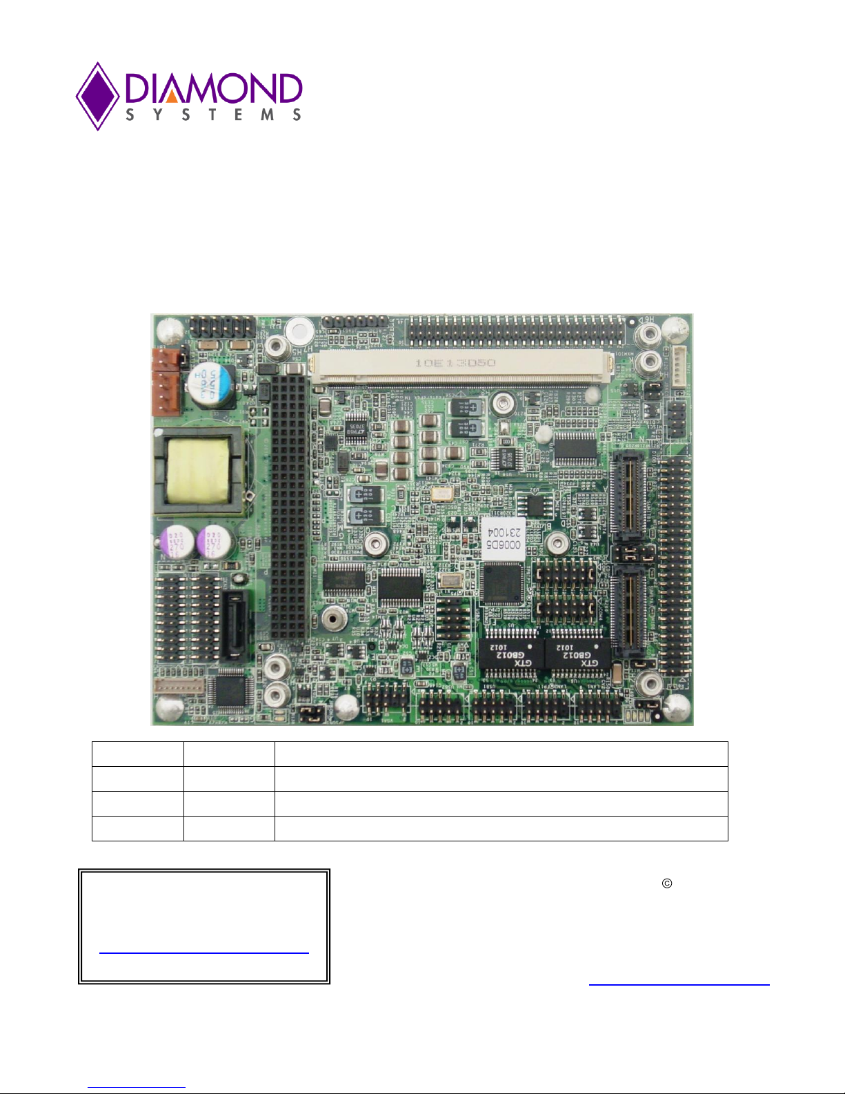
The Magellan Embedded-Ready Subsystem is a high performance, highly integrated board-level embedded
single board computer matching the footprint of the popular COM Express computer-on-module (COM) standard.
Magellan’s CPU core consists of a COM Express CPU module mounted on its bottom side, an approach that
improves thermal management and increases the space for I/O functions and connectors. This innovative design
has enabled Magellan to integrate additional serial and Ethernet controllers, a complete set of peripheral interface
header connectors, a PCI-104TM expansion stack, SUMITTM bus connector, and a MXM I/O FeaturePakTM socket
all within the compact COM Express footprint.
Thanks to Magellan’s flexible architecture, you can select from a wide range of COM Express-based CPUs to
meet each application’s specific performance, power, and cost requirements. Available processors include Intel’s
Atom and Core 2 Duo CPUs.
Magellan is offered in a range of models that vary according to the choice of COM Express CPU module, on-
board SO-DIMM SDRAM capacity, and input power option as shown in the table below.
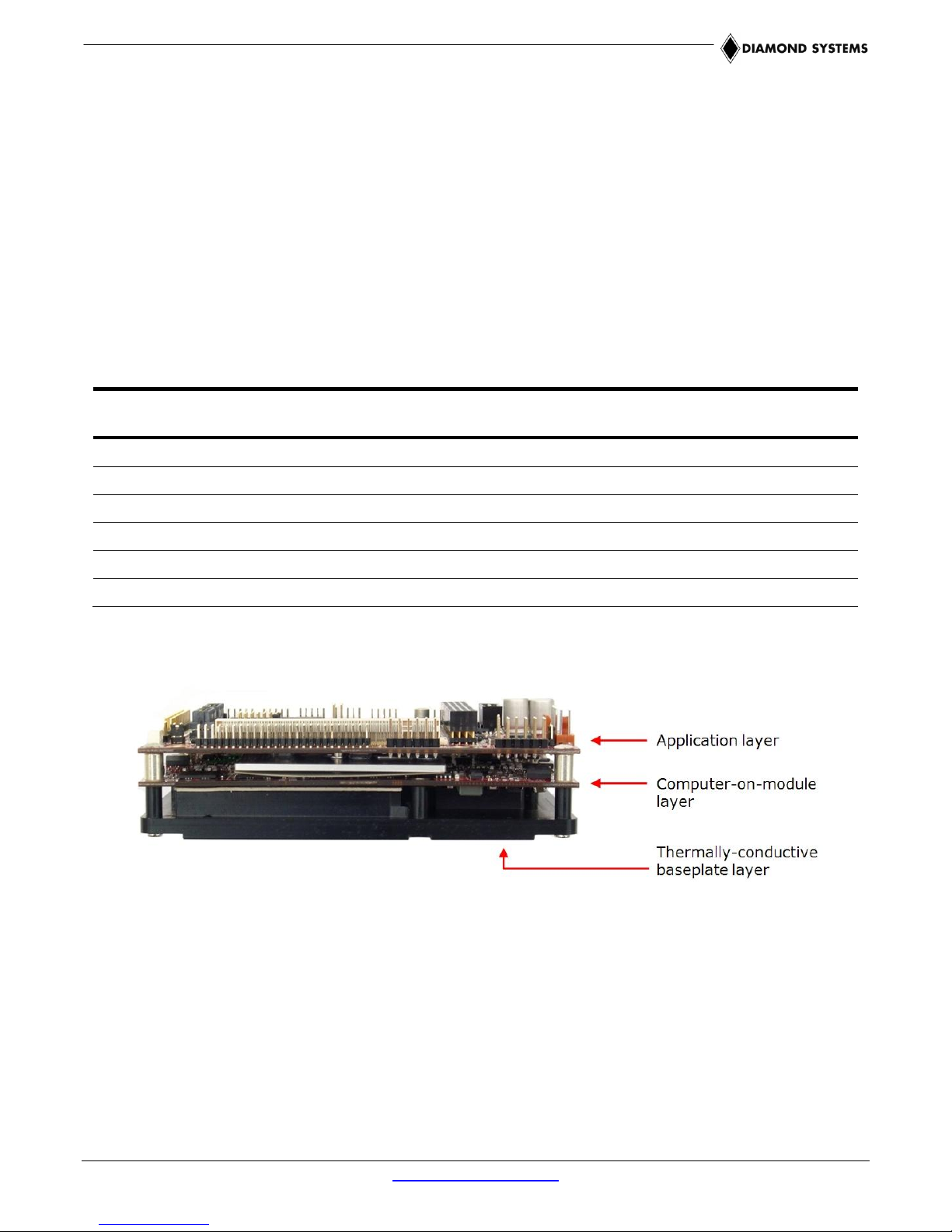
Figure 1: Edge View of the Magellan Embedded-Ready Subsystem SBC
Magellan’s features comprise functions provided by the “Magellan baseboard”, or application layer, (top board in
stack shown in Figure 1) along with functions implemented on the attached COM Express computer-on-module
(COM) macrocomponent (bottom board in stack), along with a heatspreader mounted on the bottom.
These features are summarized on the next page.
Magellan User Manual Rev A.02 www.diamondsystems.com Page 5

1.1 Magellan Features
Note: The COM Express COM features listed here are typical. Refer to the appropriate
COM Express CPU module’s user manual for detailed specifications.
CPU: choice of two COM Express CPU modules
1.1GHz Intel Atom Z510, using the CME-Z510-1G COM Express CPU module
1.6GHz Intel Core 2 Duo LV, using the CME-965-L7500 COM Express CPU module
RAM
Atom Z510: 1GB of DDR2 SDRAM soldered on-board
Core 2 Duo LV: 1GB or 4GB SO-DIMM DDR2 SDRAM
Chipset
Atom Z510: US15WPT
Core 2 Duo LV: 965GME with ICH8M
BIOS: AMI PnP Flash BIOS
Storage
One SATA port supports one device
On-board USB flashdisk socket
Serial Ports:
Two RS-232 serial ports
Two RS-232/422/485 serial ports
Four USB 2.0 ports
Networking:
1 gigabit Ethernet from COM CPU
1 gigabit Ethernet from Intel 82574 controller on baseboard
Display:
LVDS LCD flat panel interface
Diamond supports Sharp LQ121S1LG41 and LQ121S1LG42 flat panels
VGA CRT
USB keyboard and mouse
Audio: AC’97 audio CODEC; mic in, line in/out
Watchdog timer: Non-maskable interrupt or reset modes
Other I/O: SMBus; LPC interface
Expansion buses:
PCI-104 or SUMIT bus connector stackable expansion (see below)
FeaturePak™ socket ( see below)
Power
Power input: +7-36VDC or +12VDC only (LC models)
On-board power supply: Built-in +7-36V DC/DC power supply
On-board RTC backup battery; connector for external battery
Operating environment:
Temperature MAG-965-xG models: -40°C to +80° (-40°F to +176°F)
All other models: -40°C to +85° (-40°F to +185°F)
Humidity: 0-90% non-condensing
Dimensions:
MAG-Z510-1G: 4.9 x 3.7 x 1.77 in. (125 x 95 x 45 mm)
MAG-965 models: 4.9 x 3.7 x 2.24 in (125 x 95 x 57 mm)
Weight:
MAG-Z510-1G: 11.7oz (332g)
MAG-965 models: 19.2oz (544g)
Form-factor: COM Express footprint (4.92 x 3.74 in.)
Magellan User Manual Rev A.02 www.diamondsystems.com Page 6
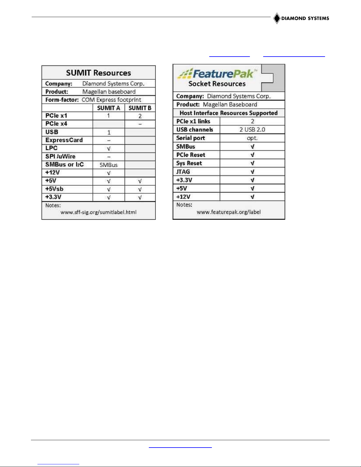
1.2 FeaturePak and SUMIT Socket Resources
Magellan’s FeaturePak and SUMIT expansion sockets provide the host interface resource support indicated in the
tables below. For further details on these expansion standards, visit FeaturePak.org and SFF-SIG.org/sumit.html.
1.3 Software Compatibility
Magellan’s operating system compatibility is a function of both the Magellan baseboard and the specific COM
Express CPU module attached to it. The baseboard and has been qualified for use with Windows XP/XPe and
Linux 2.6. The operating systems supported by the COM Express CPU module vary according to the specific
COM Express module used. Consult the appropriate COM Express CPU module’s user manual for details on its
operating system support.
1.4 Thermal Considerations and Heatspreader
All models of Magellan are specified for an operating temperature range of -40oC to +85oC. Diamond Systems
provides a heatspreader attached to the Magellan single board computer as a conductive cooled thermal layer.
However, this heatspreader by itself does not constitute the complete thermal solution necessary for any specific
implementation, but provides a common interface between the single board computer and the customer’s
implementation-specific thermal solution.
For Magellan MAG-965 models, the heatspreader is only a partial thermal solution. To achieve the full -40oC to
+85oC operating range with these models, the outside surface of the Magellan MAG-965 heatspreader must be
kept at a temperature not to exceed +85oC. If your environment exceeds this temperature specification, you are
responsible for removing the additional heat from the system through either an additional passive thermal solution
or fan solution.
Magellan’s integrated heatspreader makes thermal contact with the heat generating components and provides a
flat surface on the bottom of the assembly for mating to the system enclosure. This technique facilitates efficient
removal of heat from the COM module without the need for a fan. Four mounting holes on the bottom of the
conduction cooled heatspreader are provided to mount Magellan in an enclosure or to a bulkhead. These
mounting holes are #6-32 threaded holes on 2.8" centers.
Magellan User Manual Rev A.02 www.diamondsystems.com Page 7
2. FUNCTIONAL OVERVIEW
2.1 Block Diagrams
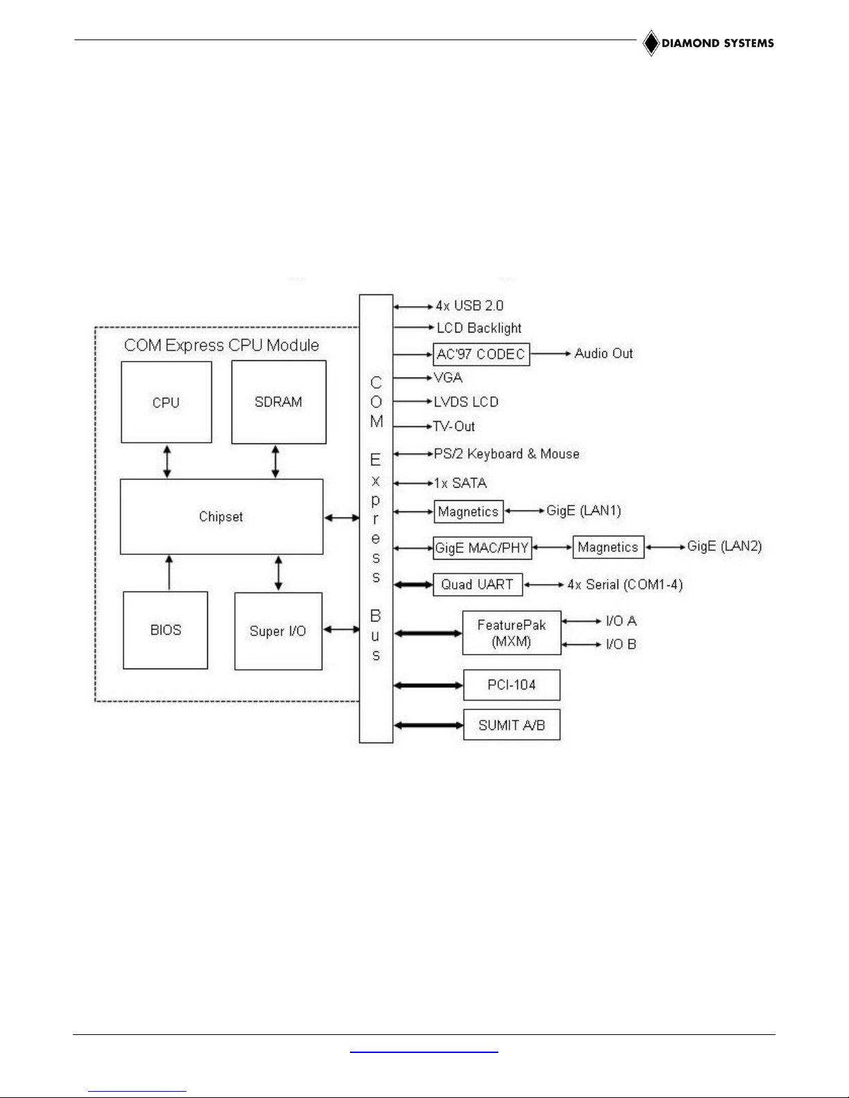
Figure 2 illustrates Magellan’s functional blocks, including circuitry contained on both the Magellan baseboard and
the COM Express CPU module. As indicated in the block diagram, the baseboard circuitry primarily comprises
interface connections and additional LAN and serial I/O, while the COM Express module integrates the system’s
core embedded PC functionality. Although COM Express CPU module processors and precise functions vary
between specific modules, the block diagram of a typical COM Express CPU module appears in Figure 3.
Figure 2: Magellan Functional Block Diagram
Magellan User Manual Rev A.02 www.diamondsystems.com Page 8
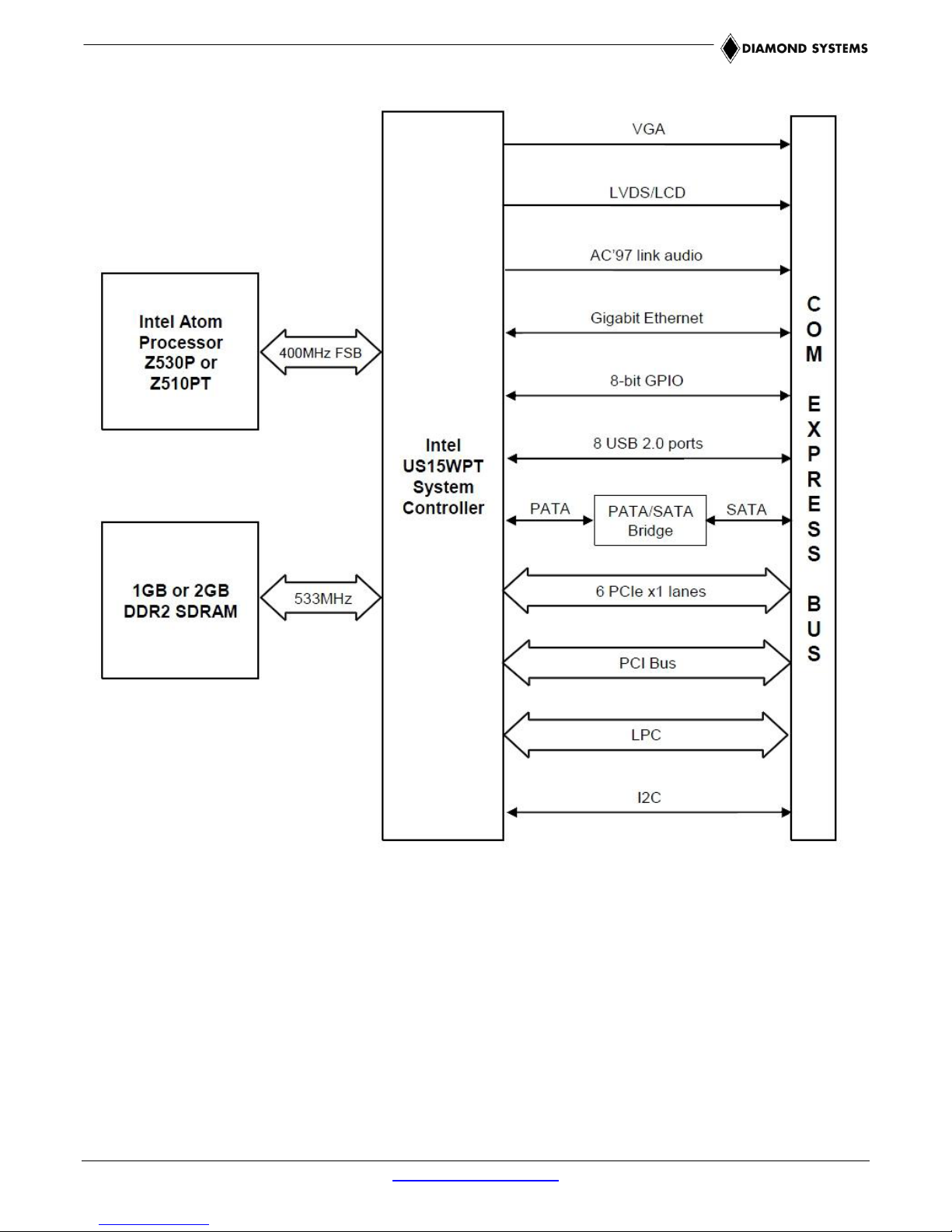
Figure 3: Typical COM Express CPU Module Functional Block Diagram
Magellan User Manual Rev A.02 www.diamondsystems.com Page 9
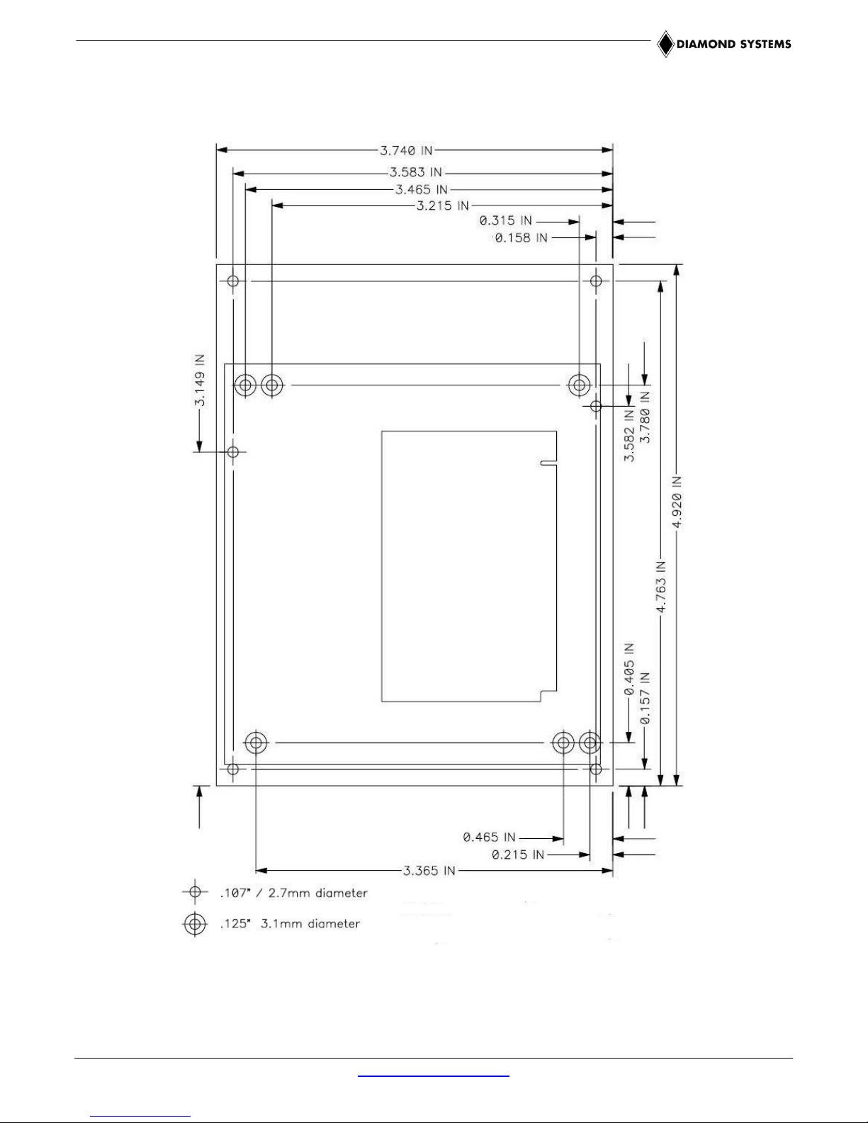
2.2 Magellan Baseboard Dimensions
Figure 4 shows the overall dimensions of the Magellan baseboard.
Magellan User Manual Rev A.02 www.diamondsystems.com Page 10
Figure 4: Baseboard Dimensions
AUDIO1
CN4
CN3
IOP1
EBT1
PWR1
PC104P1
JTAG1
MXMIO1
DIOA1
INV1
MISC1
SUMITA1
SUMITB1
DIOB1
LVDS1
(on underside of board)
SATA1
VGA1
USB3
USB2
USB1
LAN2
LAN1
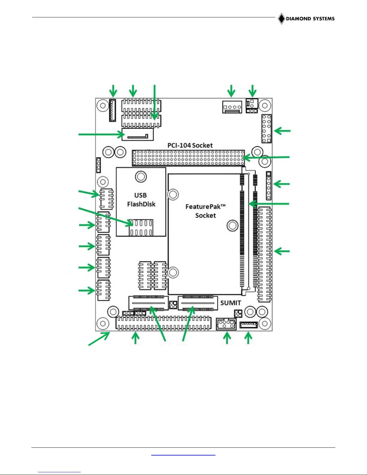
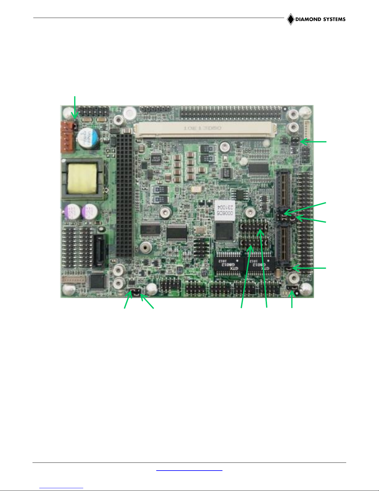
2.3 Baseboard Connector Locations
The diagram in Figure 5 illustrates the position of interface and bus connectors jumpers located on the Magellan
baseboard. Magellan’s COM Express CPU module plugs into two high-density connectors on the baseboard’s
bottom side, and is secured via screws and standoffs to the baseboard’s four corner mounting holes.
Figure 5: Magellan Baseboard Connector Locations
Magellan User Manual Rev A.02 www.diamondsystems.com Page 11
Connector Function
Silkscreen Label
Connector Type
Audio output
AUDIO1
8-pin shrouded header
Serial Ports
CN3, CN4
20-pin dual-row header
Auxiliary power output
IOP1
4-pin single-row plug
External battery input
EBT1
2-pin plug
Input power
PWR1
12-pin dual-row header
PCI-104 expansion bus
PC104P1
120-pin quad-row socket
JTAG interface
JTAG1
6-pin single-row header
FeaturePak socket
MXMIO1
230-pin MXM socket
I/O Connector A
DIOA1
50-pin dual-row header
LCD backlight
INV1
6-pin shrouded header
Auxiliary signals
MISC1
8-pin dual-row socket
SUMIT bus
SUMITA1,
52-pin female sockets
I/O Connector B
DIOB1
50-pin dual-row header
Gigabit Ethernet
LAN1, LAN2
10-pin dual-row header
USB ports 0-3
USB1, USB2
10-pin dual-row header
USB flash module socket
USB3
10-pin dual-row header
VGA
VGA1
10-pin dual-row header
SATA
SATA1
Standard SATA interface connector
LCD panel interface
(LVDS)
JLVDS1
20-pin single-row socket
(on Magellan baseboard underside)
2.3.1 Connector Summary
The following table summarizes the functions of Magellan’s interface, utility, and power connectors. Signal
functions relating to all of Magellan’s interface connectors are discussed in greater detail in Section 4 of this
document.
Note: Diamond offers an optional Magellan Cable Kit (C-MAG-KIT), which provides mating cable
assemblies for most of Magellan’s I/O interface connectors.
Magellan User Manual Rev A.02 www.diamondsystems.com Page 12
JPSON2
JPSON1
JCOM4
JCOM3
JINV1
JVLCD1
JLCD1
JCOM2
JBKC1
JBAT1
2.4 Baseboard Configuration Jumpers
Figure 6 shows the configuration jumper groups that are located on the topside of the Magellan baseboard. Refer
to Section 5 of this document for details on the functions and configuration options associated with each jumper
group.
Figure 6: Magellan Baseboard Configuration Jumper Groups
Magellan User Manual Rev A.02 www.diamondsystems.com Page 13
Important Safe-Handling Information
WARNING: ESD-Sensitive Electronic Equipment!
Observe ESD-safe handling procedures when working
with this product.
Always use this product in a properly grounded work area
and wear appropriate ESD-preventive clothing and/or
accessories.
Always store this product in ESD-protective packaging
when not in use.
Please refer to page 4 of this manual (“Important Safe-Handling Information”) for further
details.
Jumper Group Function
Silkscreen Label
Array Size
External CMOS/RTC backup battery enable
JBAT1
1 x 3
LCD backlight mode select
JBKC1
2 x 2
LCD panel signal control
JLCD1
2 x 2
LCD panel power select (3.3V/5V)
JVLCD1
1 x 3
LCD backlight inverter power select (5V/12V)
JINV1
1 x 3
Serial port COM4 mode select
JCOM4
2 x 7
Serial port COM3 mode select
JCOM3
2 x 7
Serial port signals to MXM or Supper I/O
(COM2)
JCOM2
2 x 3
On-board power supply power-up/down
behavior
JPSON1
1 x 3
On-board power supply power-up/down
behavior
JPSON2
1 x 3
2.4.1 Configuration Jumper Summary
The Magellan baseboard’s configuration jumpers are listed below. Refer to Section 5 of this document for details
regarding the configuration of these jumper groups.
3. GETTING STARTED
First-time Magellan users normally receive the product as part of Diamond’s Magellan Development Kit, which
provides everything needed to ensure rapid application development. This section of the Magellan User Manual
covers basic hardware setup, power connection, system boot-up, and initial software configuration. After Magellan
is up and running, refer to the later sections of this manual for the detailed hardware and software reference
information needed to adapt the product to specific applications.
Magellan User Manual Rev A.02 www.diamondsystems.com Page 14
 Loading...