

Page 1

JAR-VLA
FLIGHT MANUAL
DA 20/100
Category of Airworthiness : NORMAL
Applicable Airworthiness Requirements :JAR VLA incl. Amendment VLA/92/1
Serial No. :
Registration :
Date of Issue : 20 December, 2000
Document No. : DA202-100-VLA
This manual must be carried in the aircraft at all times! Scope and revision status can be found in the List
of Effective Pages and in the Record of Revisions.
The pages identified as "DOT-appr." in the List of Effective Pages are approved by:
Signature
Authority
Date of approval 20 December, 2000
This airplane is to be operated in compliance with the information and limitations contained herein.
William Jupp
Chief, Flight test
For Director, Aircraft Certification
Transport Canada
Page
0 - 1
Page 2

DIAMOND AIRCRAFT DA 20/100 Flight Manual
PREFACE
Congratulations on your choice of the DA 20/100 KATANA.
Safe handling of an airplane increases and ensures your safety and provides you with many hours of
enjoyment. For this reason you should take the time to familiarize yourself with your KATANA airplane.
We ask that you carefully read this Flight Manual and pay special attention to the recommendations
given. A careful study of the manual will reward you with many hours of trouble-free flight operation of
your KATANA airplane.
All rights reserved. Reproduction of this manual or any portion
thereof by any means without the express written permission of
DIAMOND AIRCRAFT INDUSTRIES prohibited.
Copyright
by DIAMOND AIRCRAFT INDUSTRIES,
London, Ontario
Doc # DA202-100-VLA 20 December, 2000 Page
Issue 1 0 - 2
Canada
Page 3

DIAMOND AIRCRAFT DA 20/100 Flight Manual
TABLE OF CONTENTS
Chapter
GENERAL 1
OPERATING LIMITATIONS
EMERGENCY PROCEDURES
NORMAL OPERATING PROCEDURES
PERFORMANCE
5
WEIGHT AND BALANCE / EQUIPMENT LIST
DESCRIPTION OF THE AIRPLANE AND ITS SYSTEMS
HANDLING, PREVENTIVE AND CORRECTIVE MAINTENANCE
2
3
4
6
7
8
SUPPLEMENTS 9
Doc # DA202-100-VLA 20 December, 2000 Page
Issue 1 0 - 3
Page 4
DIAMOND AIRCRAFT DA 20/100 Flight Manual
LIST OF EFFECTIVE PAGES
Chapter
0 0-1 20 Dec., 2000 3 DOT-appr 3-1 18 Nov., 2003
0-2 20 Dec., 2000 DOT-appr 3-2 09 Mar., 2001
0-3 20 Dec., 2000 DOT-appr 3-3 20 Dec., 2000
0-4 22 Aug., 2006
0-5 March 19, 2004
0-6 22 Aug., 2006
0-7 20 Dec., 2000 DOT-appr 3-7 20 Dec., 2000
0-8 20 Dec., 2000 DOT-appr 3-8 20 Dec., 2000
0-9 18 Nov., 2003 DOT-appr 3-9 20 Dec., 2000
DOT-appr 3-10 20 Dec., 2000
1 1-1 20 Dec., 2000 DOT-appr 3-11 20 Dec., 2000
1-2 20 Dec., 2000 DOT-appr 3-12 20 Dec., 2000
1-3 20 Dec., 2000 DOT-appr 3-13 09 Mar., 2001
1-4 20 Dec., 2000 DOT-appr 3-14 20 Dec., 2000
1-5 20 Dec., 2000 DOT-appr 3-15 20 Dec., 2000
1-6 20 Dec., 2000 DOT-appr 3-16 20 Dec., 2000
1-7 18 Nov., 2003 DOT-appr 3-17 20 Dec., 2000
1-8 22 Aug., 2006
1-9 09 Mar., 2001
1-14 20 Dec., 2000 DOT-appr 4-5 20 Dec., 2000
DOT-appr 4-6 20 Dec., 2000
2 DOT-appr. 2-1 20 Dec., 2000 DOT-appr 4-7 20 Dec., 2000
DOT-appr 2-2 20 Dec., 2000 DOT-appr 4-8 20 Dec., 2000
DOT-appr 2-3 20 Dec., 2000 DOT-appr 4-9 20 Dec., 2000
DOT-appr 2-4 20 Dec., 2000 DOT-appr 4-10 20 Dec., 2000
DOT-appr 2-5 18 Nov., 2003 DOT-appr 4-11 20 Dec., 2000
DOT-appr 2-6 09 Mar., 2001 DOT-appr 4-12 20 Dec., 2000
DOT-appr 2-7 18 Nov., 2003 DOT-appr 4-13 20 Dec., 2000
DOT-appr 2-8 20 Dec., 2000 DOT-appr 4-14 20 Dec., 2000
DOT-appr 2-9 20 Dec., 2000 DOT-appr 4-15 20 Dec., 2000
DOT-appr 2-10 20 Dec., 2000 DOT-appr 4-16 20 Dec., 2000
DOT-appr. 2-11 20 Dec., 2000 DOT-appr 4-17 20 Dec., 2000
DOT-appr 2-12 20 Dec., 2000 DOT-appr 4-18 20 Dec., 2000
DOT-appr 2-13 20 Dec., 2000
DOT-appr 2-14 20 Dec., 2000
DOT-appr 2-15 22 Aug., 2006
DOT-appr 2-16 20 Dec., 2000
DOT-appr 2-17 20 Dec., 2000
Page Date Chapter
1-10 20 Dec., 2000 4 DOT-appr 4-1 20 Dec., 2000
1-11 20 Dec., 2000 DOT-appr 4-2 20 Dec., 2000
1-12 20 Dec., 2000 DOT-appr 4-3 20 Dec., 2000
1-13 20 Dec., 2000 DOT-appr 4-4 20 Dec., 2000
DOT-appr 3-4 20 Dec., 2000
DOT-appr 3-5 20 Dec., 2000
DOT-appr 3-6 20 Dec., 2000
DOT-appr 3-18 20 Dec., 2000
Page Date
Doc # DA202-100-VLA
Revision 4 0 - 4
22 August, 2006 Page
Page 5
DIAMOND AIRCRAFT DA 20/100 Flight Manual
Chapter Page Date Chapter Page Date
5 DOT-appr 5-1 March 19, 2004 7-17 20 Dec., 2000
5-2 20 Dec., 2000 7-18 20 Dec., 2000
DOT-appr 5-3 20 Dec., 2000
5-4 20 Dec., 2000 8 8-1 20 Dec., 2000
DOT-appr 5-5 20 Dec., 2000 8-2 20 Dec., 2000
DOT-appr 5-6 20 Dec., 2000 8-3 20 Dec., 2000
DOT-appr 5-7 March 19, 2004 8-4 20 Dec., 2000
DOT-appr 5-8 March 19, 2004 8-5 20 Dec., 2000
DOT-appr 5-9 March 19, 2004 8-6 20 Dec., 2000
DOT-appr 5-10 March 19, 2004 8-7 20 Dec., 2000
DOT-appr 5-11 March 19, 2004
DOT-appr 5-12 March 19, 2004 9 9-1 20 Dec., 2000
DOT-appr 5-13 March 19, 2004 9-2 20 Dec., 2000
DOT-appr 5-14 March 19, 2004
DOT-appr 5-15 March 19, 2004 Supp. 1 S1-1 20 Dec., 2000
S1-2 20 Dec., 2000
6 DOT-appr. 6-1 20 Dec., 2000 S1-3 20 Dec., 2000
DOT-appr 6-2 20 Dec., 2000
DOT-appr 6-3 20 Dec., 2000
DOT-appr 6-4 20 Dec., 2000
6-5 20 Dec., 2000
6-6 20 Dec., 2000
DOT-appr 6-7 20 Dec., 2000
DOT-appr 6-8 09 Mar., 2001
DOT-appr 6-9 09 Mar., 2001
DOT-appr 6-10 18 Nov., 2003
6-11 20 Dec., 2000
6-12 20 Dec., 2000
6-13 20 Dec., 2000
6-14 20 Dec., 2000
6-15 20 Dec., 2000
7 7-1 20 Dec., 2000
7-2 20 Dec., 2000
7-3 20 Dec., 2000
7-4 20 Dec., 2000
7-5 20 Dec., 2000
7-6 20 Dec., 2000
7-7 20 Dec., 2000
7-8 20 Dec., 2000
7-9 20 Dec., 2000
7-10 20 Dec., 2000
7-11 20 Dec., 2000
7-12 18 Nov., 2003
7-13 20 Dec., 2000
7-14 20 Dec., 2000
7-15 20 Dec., 2000
7-16 20 Dec., 2000
Doc # DA202-100-VLA March 19, 2004 Page
Revision 3 0 - 5
Page 6
Page 7

DIAMOND AIRCRAFT DA 20/100 Flight Manual
[INTENTIONALLY LEFT BLANK]
Doc # DA202-100-VLA 20 December, 2000 Page
Issue 1 0 - 7
Page 8
DIAMOND AIRCRAFT DA 20/100 Flight Manual
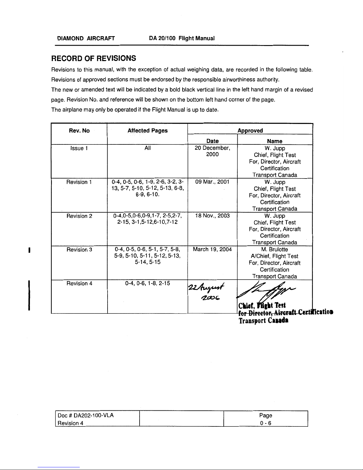
REVISION LOG
This log should be used for control of all revisions issued and installed in this manual. The affected
pages of any revision as well as the Record of Revisions must be inserted into the manual upon receipt.
The pages superseded by the revision must be removed and destroyed. The Revision Log should be
updated by hand. Changes are identified on those pages affected by a revision bar.
Rev. No. Date Issued: Inserted On: Inserted By:
Issue 1
20 Dec., 2000 20 Dec., 2000
Diamond Aircraft
Doc # DA202-100-VLA 20 December, 2000 Page
Issue 1 0 - 8
Page 9

DIAMOND AIRCRAFT DA 20/100 Flight Manual
SUBSCRIPTION SERVICE
Diamond Aircraft Publications Revision Subscription Contacts
To ensure safe operation and maintenance of the DA20/100 Katana aircraft, it is recommended
that operators verify that their documentation is at the correct issue/revision levels. For revision
and subscription service please contact the following:
1. DA20/100 Katana related manuals and publications.
North America, Australia, South Africa: Europe, Other:
Diamond Aircraft Industries Inc.
Customer Support
1560 Crumlin Sideroad
London, Ontario
Canada
N5V 1S2
www.diamondair.com
Phone:
Fax:
519-457-4041
519-457-4045
Diamond Aircraft Industries GmbH
Customer Support
N.A. Otto-Strasse 5
A-2700 Wiener Neustadt
Austria
www.diamond-air.at
Phone:
Fax:
011-43-2622-26700
011-43-2622-26780
2. Rotax 912 Engine related manuals and publications.
North America:
Rotech Research Canada LTD.
6235 Okanagan Landing Road
Vernon, British Columbia
Canada
V1H 1M5
www.rotec.com
Phone:
Fax:
OR Contact your authorized Rotax Engine distributor as listed in the back of the 912 Operators Manual.
3. Hoffmann Propeller Model HO-V352 related manuals and publications.
North America, Australia, South Africa: Europe, Other:
Diamond Aircraft Industries Inc.
Customer Support
1560 Crumlin Sideroad
London, Ontario
Canada
N5V 1S2
www.diamondair.com
Phone:
Fax:
250-260-6299
250-260-6269
519-457-4041
519-457-4045
HB- FLUGTECHNIK GES.M.B.H.
Dr. Adolf Scharf Str. 44
A-4053HAID
www.rotax.bombardier.com
Phone:
Fax:
Hoffmann Propeller GmbH. & Co.
Customer Support
Kupferlingstr. 9
D-83022 Rosenheim
Germany
Phone:
Fax:
07229 / 79104/79117
07229 / 79104 15
011-49-8031-1878-0
011-49-8031-1878-78
Doc # DA202-100-VLA November 18, 2003 Page
Revision 2 0 - 9
Page 10

DIAMOND AIRCRAFT DA 20/100 Flight Manual General
CHAPTER 1
GENERAL
1.1. INTRODUCTION 1- 1
1.2. CERTIFICATION BASIS 1- 2
1.3. WARNINGS, CAUTIONS, AND NOTES 1- 2
1.4. THREE-VIEW-DRAWING OF AIRPLANE 1- 3
1.5. DIMENSIONS 1- 4
1.6. ENGINE 1- 5
1.7. PROPELLER 1- 5
1.8. FUEL 1- 6
1.9. LUBRICANT AND COOLANT 1- 7
1.10. WEIGHT 1- 9
1.11. LIST OF DEFINITIONS AND ABBREVIATIONS 1-10
1.12. CONVERSION FACTORS 1-14
1.1. INTRODUCTION
The Airplane Flight Manual has been prepared to provide pilots and instructors with information for the
safe and efficient operation of this airplane.
This Manual includes the material required by JAR-VLA including amendment VLA/92/1. It also contains
supplemental data supplied by the airplane manufacturer that can be useful to the pilot.
The Flight Manual conforms to a standard equipped DA 20/100 KATANA. Any optional equipment
installed on request of the customer (COMM, NAV, etc.) is not considered.
For the operation of optional equipment the Operation Manual of the respective vendor must be used.
For permissible accessories refer to the equipment list, Section 6.5.
Doc # DA202-100-VLA 9 March, 2001 Page
Revision 1 1 - 1
Page 11
DIAMOND AIRCRAFT DA 20/100 Flight Manual General
1.2. CERTIFICATION BASIS
The DA 20/100 has been approved by Transport Canada as meeting the requirements of JAR-VLA and
amendment VLA/92/1. The Type Certificate No. A-191, originally issued on July 29th, 1994, has been
revised to include the DA20/100.
Category of Airworthiness: NORMAL
Noise Certification Basis: a) Canadian Airworthiness Manual Chapter 516
b) FAA Part 36
c) LBA: LSL Chapter X of 1.01.1991
For others, refer to the national type certificate data sheets, as applicable.
1.3. WARNINGS, CAUTIONS, AND NOTES
The following definitions apply to warnings, cautions, and notes used in the Flight Manual:
WARNING
means that the non-observation of the corresponding procedure leads to an
immediate or important degradation of the flight safety.
CAUTION
means that the non-observation of the corresponding procedure leads to a
minor or to a more or less long term degradation of flight safety.
NOTE
draws the attention to any special item not directly related to safety but
which is important or unusual.
Doc # DA202-100-VLA 9 March, 2001 Page
Revision 1 1 - 2
Page 12
DIAMOND AIRCRAFT DA 20/100 Flight Manual General
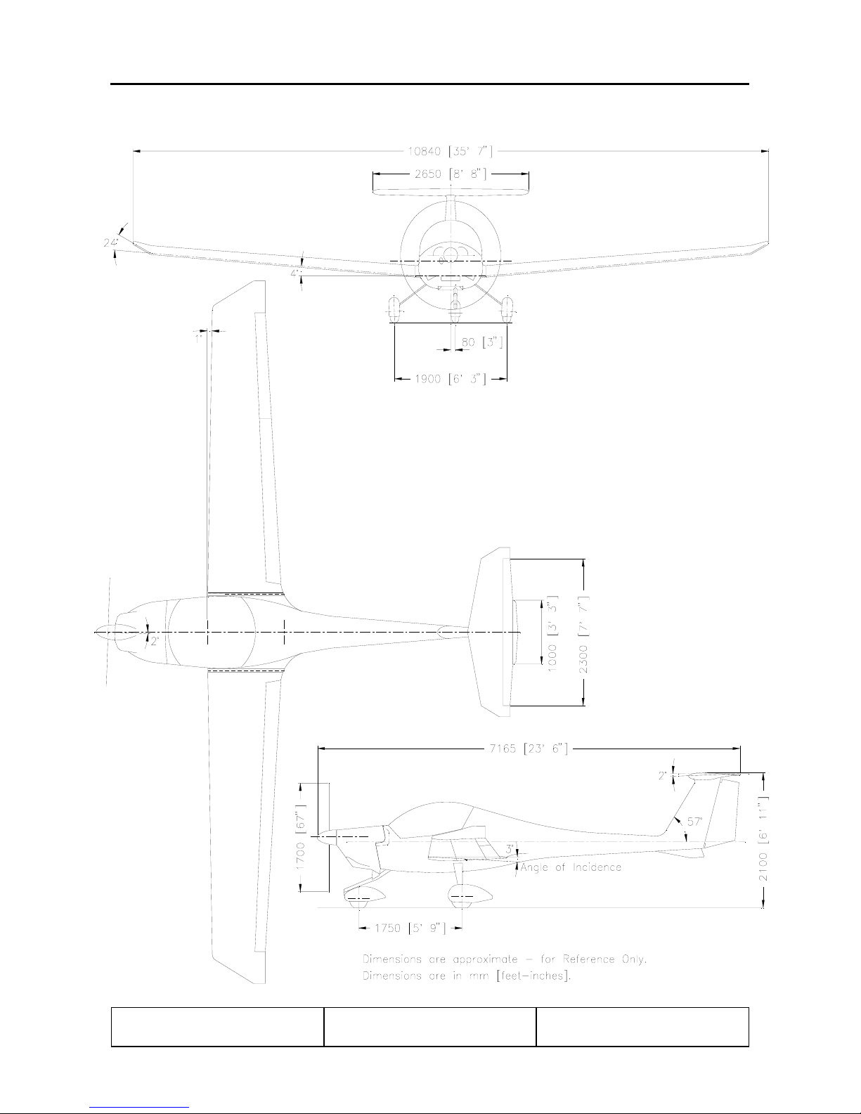
1.4. THREE-VIEW-DRAWING OF AIRPLANE
Doc # DA202-100-VLA 9 March, 2001 Page
Revision 1 1 - 3
Page 13

DIAMOND AIRCRAFT DA 20/100 Flight Manual General
1.5. DIMENSIONS
1.5.1 Overall Dimensions
Span: 35 ft 7 in (10.84 m)
Length: 23 ft 6.0 in ( 7.17 m)
Height: 6 ft 11.0 in ( 2.10m)
1.5.2 Wing
Airfoil: Wortmann FX 63-137/20 HOAC
2
Wing Area: 125 sq.ft. (11.6 m
Mean Aerodynamic
3 ft 6.9 in ( 1.09 m)
)
Chord (MAC):
Aspect Ratio: 10.0
Dihedral: +4° nominal
Sweep of Leading Edge: +1° nominal
1.5.3 Horizontal Stabilizer
Angle of Incidence : -2.5° ±0.5°
Span: 8 ft 8 in (2.65 m)
1.5.4 Landing Gear
Track: 6 ft 3 in (1.90 m)
Wheel Base: 5 ft 9 in (1.75 m)
Tire Size:
Nose:
4.00-4 (TOST)
Tire Pressure:
Main:*
Nose:
Main:
* Main tires must be same brand, model and size.
Doc # DA202-100-VLA 9 March, 2001 Page
Revision 1 1 - 4
5.00-4 (GOODYEAR)
15 x 6.00-5 (GOODYEAR) or
5.00 x 5, 6 Ply (TSO C62)
26 psi (1.8 bar)
33 psi (2.3 bar)
Page 14

DIAMOND AIRCRAFT DA 20/100 Flight Manual General
1.6. ENGINE
Rotax 912S, 4 Cylinder, 4 Stroke-Engine, horizontally opposed, liquid cooled cylinder heads, air-cooled
cylinders.
Propeller drive via integrated reduction gear.
Reduction Ratio: 2.43 : 1
Displacement: 82.5 cu.in. (1.352 liters)
Output Power: 100 hp (73.5 kW)
at 2385 RPM
1.7. PROPELLER
Two-bladed variable pitch propeller,
manufactured by HOFFMANN,
Constant speed, hydraulic pitch control
Range of Pitch Angle:
Diameter: 5 ft 6.9 in (1.70 m)
model HO-V352F/170FQ OR
model HO-V352F/C170FQ
10° - 35°
Doc # DA202-100-VLA 9 March, 2001 Page
Revision 1 1 - 5
Page 15
DIAMOND AIRCRAFT DA 20/100 Flight Manual General
1.8. FUEL
Approved Fuel Grades: AVGAS 100LL
Automotive Gasoline, Unleaded, Minimum
95 RON or 91 AKI
RON = Research Octane Number
MON = Motor Octane Number
AKI = Anti Knock Index =
Total Fuel Capacity:
Usable Fuel: 19.5 US gal. (74 liters)
Unusable Fuel: 0.6 US gal. ( 2 liters)
Specifications: Europe - EN 228
USA - ASTM D4814
Canada –
20.1 US gal. (76 liters)
(or more current issue)
MON + RON
2
CAN/CGSB-3.5-94
CAUTION
Use of automotive gasoline containing alcohol (e.g.: methanol or
ethanol) other than specified in the above listed specifications, is not
permitted.
Petroleum suppliers provide automotive gasoline of varying volatilities, depending on the
season and climatic zone. Fuels with higher volatility (“cold weather” grade fuels) are
more susceptible to fuel vapour formation than fuels with lower volatility (“hot weather”
grade fuels), at equal temperatures. Use of fuels dispensed in winter or in colder climatic
zones, under high ambient temperature conditions, increases the risk of vapor formation
and subsequent possible engine malfunction.
Doc # DA202-100-VLA 9 March, 2001 Page
Revision 1 1 - 6
NOTE
Page 16
DIAMOND AIRCRAFT DA 20/100 Flight Manual General
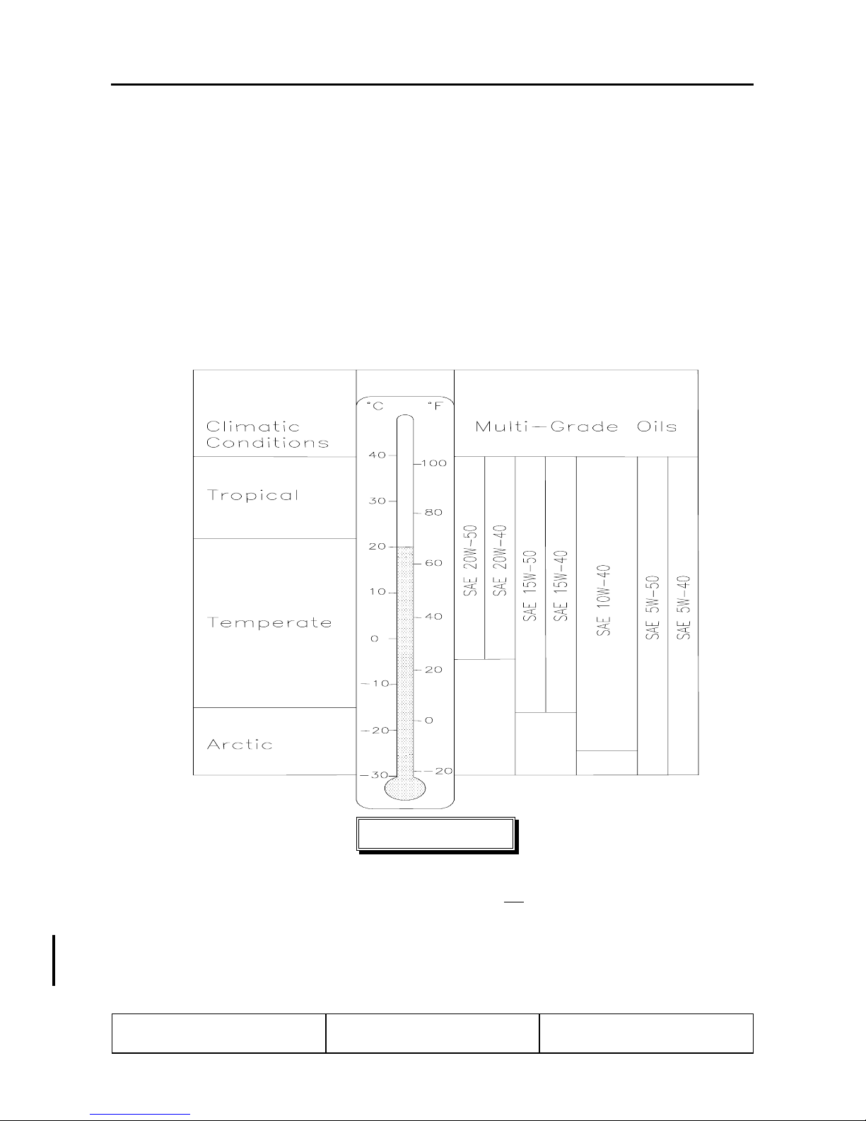
1.9. LUBRICANT AND COOLANT
1.9.1. Lubricant
Use only motor oil with API classification SF or SG or higher.
Due to high stresses in the reduction gears, a 4 stroke motorcycle oil of a registered brand with gear additives
that meets API classification SF or SG are highly recommended.
The viscosity should be selected according to the various climatic conditions using the following table.
When operating with AVGAS100LL fuel do not
Oil Capacity: Minimum : 3.0 liters (3.2 US qt.)
Maximum : 3.4 liters (3.6 US qt.)
Doc # DA202-100-VLA November 18, 2003 Page
Revision 2 1 - 7
CAUTION
Do not use aviation lubricant!
use synthetic oil.
Page 17
DIAMOND AIRCRAFT DA 20/100 Flight Manual
General
1.9.2. Coolant
EVANS NPG+ waterless coolant or a comparable coolant must be used without water or other
additives.
WARNING
Water or water-containing coolant must not be added in any case to the cooling system.
CAUTION
The coolant manufacturer’s data for change/replacement, usage, and operation are to be
observed.
(a) Coolant Capacity:
Minimum
Maximum : 2.6 US qt. (2.5 liters)
(b) Reservoir Capacity:
Minimum
Maximum : 0.21 US qt. (0.2 liters)
: 2.5 US qt. (2.4 liters)
: 0.11 US qt. (0.1 liters)
NOTE
The level in the reservoir can be checked using the coolant dipstick. Excessive overfilling
of the reservoir can result in overflow during operation. In the event of a completely empty
reservoir, the coolant level in the dispatcher vessel on top of the engine must also be
checked.
Doc # DA202-100-VLA August 22, 2006 Page
Revision 4 1 - 8
Page 18

DIAMOND AIRCRAFT DA 20/100 Flight Manual General
1.10. WEIGHT
Maximum Take-off Weight : 750 kg (1653 lbs)
Maximum Landing Weight : 750 kg (1653 lbs)
Empty Weight : See Chapter 6
Maximum Weight in Baggage Compartment
: 20 kg (44 lbs)
only if restraining devices available
Wing Loading
At Maximum Take-off Weight
: 64.61 kg/m
2
(13.23 lbs/sq.ft.)
Performance Load at Max. Take-off Weight : 7.50 kg/hp (16.53 lbs/hp.)
Doc # DA202-100-VLA 9 March, 2001 Page
Revision 1 1 - 9
Page 19

DIAMOND AIRCRAFT DA 20/100 Flight Manual General
1.11. LIST OF DEFINITIONS AND ABBREVIATIONS
1.11.1. Speed
AGL: Above Ground Level
CAS: Calibrated airspeed; Indicated speed corrected for installation and instrument errors.
CAS is equal to TAS at standard atmospheric conditions at MSL.
KCAS: CAS in knots.
IAS: Indicated airspeed as shown on the airspeed indicator.
KIAS: IAS indicated in knots.
GS: Ground Speed. Speed of the airplane relative to the ground.
TAS: True airspeed. Speed of the airplane relative to air. TAS is CAS corrected for altitude and
temperature errors.
: Maneuvering speed. Maximum speed at which the airplane is not overstressed at full
v
A
deflection of control surfaces.
v
: Maximum speed with flaps extended.
FE
: Speed which must never be exceeded in any operation.
v
NE
: Maximum structural cruising speed which should only be exceeded in calm air, and then
v
NO
only with caution.
: The power-off stall speed with the airplane in its standard configuration.
v
S
: The power-off stall speed with the airplane in landing configuration.
v
SO
: Best angle-of-climb speed.
v
X
v
: Best rate-of-climb speed.
Y
Doc # DA202-100-VLA 20 December, 2000 Page
Issue 1 1 - 10
Page 20

DIAMOND AIRCRAFT DA 20/100 Flight Manual General
1.11.2. Meteorological Terms
ISA: International Standard Atmosphere at which air is identified as a dry gas. The temperature at
mean sea level is 15° Celsius (59° F), the air pressure at sea level is 1013.25 mbar (29.92 inHg),
the temperature gradient up to the altitude at which the temperature reaches -56.5° C (-67.9° F)
is -0.0065° C/m (-0.0036° F/ft) and 0° C/m (0° F/ft) above.
OAT: Outside air temperature.
AGL: Above Ground Level
Indicated Pressure Altitude:
Altitude reading with altimeter set to 1013.25 mbar (29.92 inHg) air pressure.
Pressure Altitude:
Altitude measured at standard pressure at MSL (1013.25 mbar / 29.92 inHg) using a barometric
altimeter. Pressure altitude is the indicated altitude corrected for installation and instrument
errors. Within this manual the instrument errors are assumed to be zero.
Aerodrome/Airport Pressure:
Actual atmospheric pressure at the aerodrome/airport altitude.
Wind: The wind speeds used in the diagrams in this manual should be referred to as headwind or
tailwind components of the measured wind.
1.11.3. Powerplant
Take-off Power:
Maximum engine power for take-off.
Maximum Continuous Power:
Maximum permissible continuous engine output power during flight.
Doc # DA202-100-VLA 20 December, 2000 Page
Issue 1 1 - 11
Page 21

DIAMOND AIRCRAFT DA 20/100 Flight Manual General
1.11.4. Flight Performance and Flight Planning
Demonstrated Crosswind Component:
The maximum speed of the crosswind component at which the maneuvrability of the airplane
during take-off and landing has been demonstrated during type certification test flights.
Service Ceiling:
The altitude at which the maximum rate of climb is 0.5 m/s (100 ft/min.).
1.11.5. Weight and Balance
Reference Datum (RD):
An imaginary vertical plane from which all horizontal distances for the center of gravity
calculations are measured. It is the plane through the leading edge of the wing root rib,
perpendicular to the longitudinal axis of the airplane.
Station:
A defined point along the longitudinal axis which is generally presented as a specific distance
from the reference datum.
Lever Arm:
The horizontal distance from the reference datum to the center of gravity (of a component).
Moment:
The weight of a component multiplied by its lever arm.
Center of Gravity (CG):
Point of equilibrium for the airplane weight.
CG position:
Distance from the reference datum to the CG. It is determined by dividing the total moment (sum
of the individual moments) by the total weight.
Doc # DA202-100-VLA 20 December, 2000 Page
Issue 1 1 - 12
Page 22

DIAMOND AIRCRAFT DA 20/100 Flight Manual General
Center of Gravity Limits:
The CG range which an airplane with a given weight must be operated within.
Usable Fuel:
The amount of fuel available for the flight plan calculation.
Unusable Fuel:
The amount of fuel remaining in the tank, which cannot be safely used in flight.
Empty Weight:
Weight of the airplane including unusable fuel, all operating fluids and maximum oil amount.
Useful Load:
The difference between take-off weight and empty weight.
Maximum Take-off Weight:
Maximum weight permissible for take-off.
1.11.6. Equipment
ACL: Anti collision light
1.11.7 Miscellaneous
GFRP - Glass Fibre Reinforced Plastic
CFRP - Carbon Fibre Reinforced Plastic
Doc # DA202-100-VLA 20 December, 2000 Page
Issue 1 1 - 13
Page 23

DIAMOND AIRCRAFT DA 20/100 Flight Manual General
1.12. CONVERSION FACTORS
1.12.1. Length or Altitude
1 [ft.] = 0.3048 [m]
1 [in.] = 25.4 [mm]
1.12.2. Speed
1 [kts] = 1.852 [km/h]
1 [mph] = 1.609 [km/h]
1.12.3. Pressure
1 [hPa] = 100 [N/m
1 [in. Hg] = 33.865 [hPa]
1 [psi] = 68.97 [mbar]
2
] = 1 [mbar]
1.12.4 Weight
1 [lbs] = 0.454 [kg]
1.12.5 Volume
1 [US gallon] = 3.785 [liters]
1 [Imperial gallon] = 4.546 [liters]
Doc # DA202-100-VLA 20 December, 2000 Page
Issue 1 1 - 14
Page 24

DIAMOND AIRCRAFT DA 20/100 Flight Manual Limitations
CHAPTER 2
OPERATING LIMITATIONS
2.1 INTRODUCTION 2-1
2.2 AIRSPEED LIMITATIONS 2-2
2.3 AIRSPEED INDICATOR MARKINGS 2-2
2.4 POWERPLANT LIMITATIONS 2-3
2.5 POWERPLANT INSTRUMENT MARKINGS 2-5
2.6 MISCELLANEOUS INSTRUMENT MARKINGS 2-5
2.7 WEIGHT 2-6
2.8 CENTER OF GRAVITY 2-6
2.9 APPROVED MANEUVERS 2-7
2.10 MANEUVERING LOAD FACTORS 2-7
2.11 MAXIMUM PASSENGER SEATING 2-8
2.12 FLIGHT CREW 2-8
2.13 KINDS OF OPERATION 2-8
2.14 FUEL 2-9
2.15 PLACARDS 2-9
2.16 DEMONSTRATED CROSSWIND COMPONENT 2-17
2.17 TEMPERATURE LIMITS 2-17
2.1. INTRODUCTION
Chapter 2 of this Flight Manual comprises the operating limitations, instrument markings, airspeed
indicator markings, and the limitation placards which are necessary for the safe operation of the airplane,
its engine, and standard systems and equipment.
The operating limitations in this Chapter and Chapter 9 have been approved by the Department of
Transport (DOT), and must be complied with for all operations.
These limitations must be complied with for all operations.
Doc # 202-100-VLA 20 December, 2000 Page
DOT Approved 2 - 1
WARNING
Page 25
DIAMOND AIRCRAFT DA 20/100 Flight Manual Limitations
2.2. AIRSPEED LIMITATIONS
IAS
Speed kts mph km/h Remarks
v
A
104 120 193 Do not make full or abrupt control
Maneuvering Speed
v
FE
81 93 150 Do not exceed this speed with flaps
Maximum Flap
Extended Speed
v
NO
118 135 218 Do not exceed this speed except in
Maximum Structural
Cruising Speed
v
NE
161 185 298 Do not exceed this speed in any operation
Never Exceed Speed
2.3. AIRSPEED INDICATOR MARKINGS
IAS
movement above this speed, because
under certain conditions the airplane may
be overstressed by full control movement.
extended
smooth air, and then only with caution
Marking kts mph km/h Explanation
White Arc 37-81 43-93 69-150 Operating range with extended flaps
Green Arc 41-118 47-135 76-218 Normal operating range
Yellow Arc 118-161 135-185 218-298 Maneuvers must be conducted with
caution and only in smooth air.
Red Line 161 185 298 Maximum permissible speed for all
operating modes
Doc # 202-100-VLA 20 December, 2000 Page
DOT Approved 2 - 2
Page 26
DIAMOND AIRCRAFT DA 20/100 Flight Manual Limitations
2.4. POWER PLANT LIMITATIONS
2.4.1. Engine
(a) Engine Manufacturer
(b) Engine Type Designation
: Bombardier Rotax, Gunskirchen/Austria
: 912 S3
NOTE
The propeller is driven by the engine via a reduction gear with a ratio of 2.43:1. The RPM
indicator indicates the propeller speed. For that reason, all speed references within this
manual - contrary to the engine manual - are propeller speeds.
(c) Engine Operating Limitations
Max. T/O Power (5 min.) : 100 hp / 73.5 kW
Max. Permissible T/O RPM : 2385 RPM
Max. Continuous Power : 93 hp / 69 kW
Max. Permissible Continuous RPM : 2260 RPM
(d) Oil Pressure
Minimum
Normal
Max. in case of Cold-start (short-term) : 102 psi (7.0 bar)
(e) Fuel Pressure
Minimum : 2.2 psi (0.15 bar)
Maximum : 5.8 psi (0.40 bar)
(f) Oil Temperature
Minimum : 122°F ( 50°C)
Maximum : 266°F (130°C)
: 12 psi (.8 bar) Below 1440 RPM
: 29 psi – 73 psi (2.0-5.0 bar) Above 1440 RPM
Doc # 202-100-VLA 20 December, 2000 Page
DOT Approved 2 - 3
Page 27

DIAMOND AIRCRAFT DA 20/100 Flight Manual Limitations
(g) Cylinder Head Temperature
Maximum : 275°F (135°C)
(h) Fuel Specifications
Approved Fuel Grades : AVGAS 100LL
(i) Oil Grades
2.4.2. Propeller
(a) Propeller Manufacturer
(b) Propeller Type
HO-V352F/C170FQ
Unleaded Automotive Fuel 95 RON /91 AKI
(refer also to page 1-6)
: 4 stroke motorcycle oil of a registered brand
with gear additives that meets or exceedes API
classification SF or SG are highly
recommended.
(also see Page 1-7 for additional information
on the selection of suitable lubricants)
: Hoffmann Propeller, Rosenheim/Germany
: HO-V352F/170FQ OR
(c) Propeller Diameter
: 5 ft 6.9 in (1.70 m)
(d) Propeller Pitch (at 3/4 radius)
(e) Propeller Speed Limitations
: 10° - 35°
Max. T/O RPM (max. 5 min.) : 2385 RPM
Max. Continuous RPM : 2260 RPM
Doc # 202-100-VLA 20 December, 2000 Page
DOT Approved 2 - 4
Page 28
DIAMOND AIRCRAFT DA 20/100 Flight Manual Limitations
2.5. POWERPLANT INSTRUMENT MARKINGS
Powerplant instrument markings and their color code significance are shown below:
Instrument Red Line
= Lower Limit
Tachometer -
Oil Temperature
Indicator
Cylinder Head
Temperature
Indicator
Oil Pressure
Indicator
* Recommended nominal idle speed = 950 RPM
122° F
50° C
- - - 275° F
12 psi
0.8 bar
Green Arc
= Normal
Operating Range
*600 - 2260 RPM
122- 266° F
50 - 130° C
29 - 73 psi
2 - 5 bar
ABOVE 1440
RPM
Yellow Arc
= Caution Range
2260 - 2385 RPM
12 – 29 psi
0.8 – 2 bar
BELOW 1440
RPM
73 - 102 psi
5 - 7 bar
2.6. MISCELLANEOUS INSTRUMENT MARKINGS
Red Line
= Upper Limit
2385 RPM
- 266° F
130° C
135° C
102 psi
7 bar
Instrument Red Line
= Lower Limit
Voltmeter 8-11 Volts 12.5 - 16 Volts 11 - 12.5 Volts 16.1 Volts
Green Arc
= Normal
Operating Range
Yellow Arc
= Caution Range
Red Line
= Upper Limit
Doc # 202-100-VLA November 18, 2003 Page
Revision 2 2 - 5
Page 29
DIAMOND AIRCRAFT DA 20/100 Flight Manual Limitations
2.7. WEIGHT
Maximum permissible weight : 750 kg (1653 lbs)
Maximum permissible weight in the baggage
compartment
: 20 kg (44 lbs)
only permissible with baggage harness
WARNING
Exceeding the weight limitations may lead to overloading of the airplane, as well as
degrading of the handling characteristics and flight performance.
2.8. CENTER OF GRAVITY
The reference datum (RD) for the center of gravity (CG) calculation is tangent to the leading edge of the
wing at the root rib. This plane is vertical when the fuselage is horizontal. Procedures for horizontal
alignment, as well as particulars with regard to the empty weight center of gravity, refer to Chapter 6.
Most forward CG (all weights) : 250 mm (9.84 in) aft of RD
Most rearward CG (all weights) : 390 mm (15.35 in) aft of RD
WARNING
Exceeding the center of gravity limitations reduces the maneuverability and stability of
the airplane.
The procedure used to determine the center of gravity is described in Chapter 6.
Doc # 202-100-VLA 9 March, 2001 Page
DOT Approved 2 - 6
Page 30
DIAMOND AIRCRAFT DA 20/100 Flight Manual Limitations
2.9. APPROVED MANEUVRES
This airplane is certified in the NORMAL Category in accordance with JAR-VLA.
Permissible Normal Category Maneuvres:
a) All normal flight maneuvres
b) Stalls (except WHIP stalls)
c) Lazy Eight’s Entry speed: 116 kts (215 km/h)
Chandelles: Entry speed: 116 kts (215 km/h)
Steep turns in which the angle of bank does not exceed 60°
NOTE
Aerobatics are prohibited.
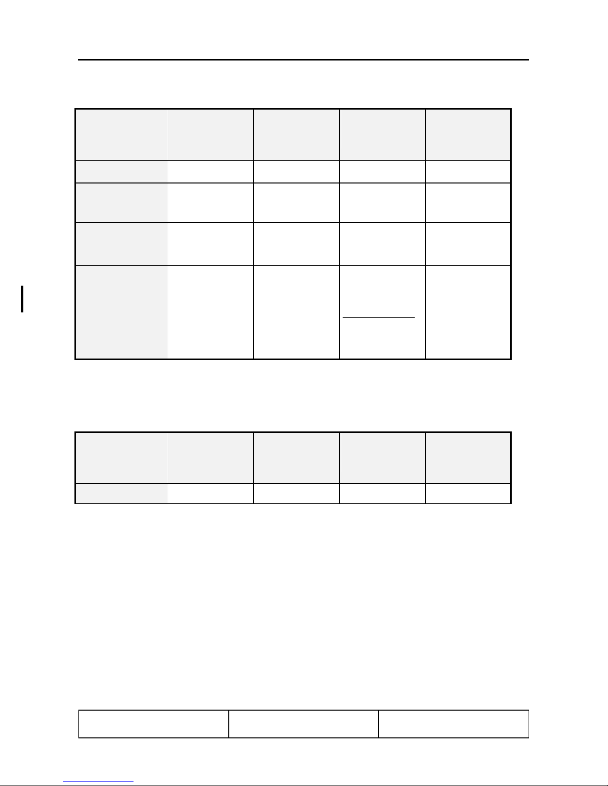
2.10. MANEUVERING LOAD FACTORS
Table of structural maximum permissible load factors:
Positive + 4.4 + 4.4 + 2.0
Negative - 2.2 - 2.2 0
at vA: at vNE: with fully
extended flaps
WARNING
Exceeding the maximum load factors will result in overstressing of the airplane.
Simultaneous full deflection of more than one control surface can result in overstressing
of the structure, even at speeds below the maneuvering speed.
Doc # 202-100-VLA November 18, 2003 Page
Revision 2 2 - 7
Page 31

DIAMOND AIRCRAFT DA 20/100 Flight Manual Limitations
2.11. MAXIMUM PASSENGER SEATING
Maximum Passenger Seating: one passenger.
2.12. FLIGHT CREW
Minimum Flight Crew: one pilot,
aircraft to be flown solo from left seat only
2.13. KINDS OF OPERATION
Flights are permissible in accordance with day visual flight rules.
Minimum Equipment, Flight and Navigation Instruments:
Airspeed Indicator
Altimeter
Magnetic Compass
Minimum Equipment, Powerplant Instruments:
Fuel Quantity Indicator
Oil Pressure Indicator
Oil Temperature Indicator
Manifold Pressure Indicator
Cylinder Head Temperature Indicator
Tachometer
Fuel Pressure Warning Light
Voltmeter
Ammeter
Generator Warning Light
Note: Additional equipment may be required for compliance with specific operational or specific national
requirements. It is the operators responsibility to ensure compliance with any such specific
equipment requirements.
Doc # 202-100-VLA 20 December, 2000 Page
DOT Approved 2 - 8
Page 32

DIAMOND AIRCRAFT DA 20/100 Flight Manual Limitations
2.14. FUEL
Fuel Capacity
Total Fuel Quantity: : 20.1 US gal. (76 liters)
Usable Fuel: : 19.5 US gal. (74 liters )
Unusable Fuel: : 0.53 US gal. ( 2 liters)
2.15. PLACARDS
The following placards must be installed:
1. On the instrument panel next to airspeed indicator
Effective for all aircraft operated strictly under JAR-VLA regulations
This airplane is classified as a very
light airplane approved for day VFR only,
in non-icing conditions. All aerobatic maneuvres, including
intentional spinning, are prohibited. See Flight Manual
for other limitations.
Doc # 202-100-VLA 20 December, 2000 Page
DOT Approved 2 - 9
Page 33

DIAMOND AIRCRAFT DA 20/100 Flight Manual Limitations
2. On the instrument panel under the airspeed
3. Next to the switches
4. On the flap control
5. On the dimming switch for trim display,
flap control and GPS (if installed)
6. Next to dimming potentiometer for cabin
and fuel shut-off valve light
Doc # 202-100-VLA 20 December, 2000 Page
DOT Approved 2 - 10
Page 34

DIAMOND AIRCRAFT DA 20/100 Flight Manual Limitations
7. On the instrument panel next to the individual circuit breakers
Depending on aircraft specific avionic
equipment configuration.
Doc # 202-100-VLA 20 December, 2000 Page
DOT Approved 2 - 11
OR
OR
Page 35

DIAMOND AIRCRAFT DA 20/100 Flight Manual Limitations
8. On top of the instrument panel under
the compass
10. On top the instrument panel within
pilot’s direct line of vision
11. On DME channeling switch on the RH
side of the radio stack (optional)
9. Around Trim Display on top of the
instrument panel
12. Above RH air vent on the instrument panel
(optional)
13. Above the OAT indicator 14. Below Microphone jack on LH side of the
instrument panel
15. On the fuel quantity gauge 16. Next to GPS (if installed)
Doc # 202-100-VLA 20 December, 2000 Page
DOT Approved 2 - 12
Page 36

DIAMOND AIRCRAFT DA 20/100 Flight Manual Limitations
17. Under the instrument panel next to the individual knobs
18. On the centre console between
throttle and propeller levers
19. On the side of the throttle quadrant next to
tension adjustment knob
20. Next to trim switch on the centre console
21. Next to instrument and map light switches
on the centre console
22. Next to fuel shut-off valve in
correct position
Doc # 202-100-VLA 20 December, 2000 Page
DOT Approved 2 - 13
Page 37

DIAMOND AIRCRAFT DA 20/100 Flight Manual Limitations
23. Next to canopy release handles
Inside Left (partially coloured red) Inside Right (partially coloured red)
Outside Left Outside Right
24. Next to ELT (if installed) to indicate switch position
for EBC 102A ELT model for EBC 502 ELT model
25. Next to Headset Jacks on the Back Rest
Pilot side (LH) Co-pilot side (RH)
Doc # 202-100-VLA 20 December, 2000 Page
DOT Approved 2 - 14
Page 38

DIAMOND AIRCRAFT DA 20/100 Flight Manual Limitations
26. On the LH side of baggage compartment 27. On the brake fluid reservoirs
(rudder pedals)
Hydraulic Fluid
MIL-H-5606
28. On inside of oil filler door (coloured red)
29. On oil filler cap
30. On coolant equalizing reservoir
31. On coolant dispatcher vessel
32. Next to fuel filler cap
DO NOT
ADD WATER
TO THIS SYSTEM
STOP!
EVANS NPG+
WATERLESS
COOLANT ONLY
Doc # 202-100-VLA
Revision 4 2 - 15
22 August, 2006 Page
Page 39

DIAMOND AIRCRAFT DA 20/100 Flight Manual Limitations
33. On fuselage upper skin behind cockpit (only if ELT is installed), coloured yellow
34. On fuselage underside (belly), by left wing
35. Under each wing and tail skid plate
36. Around Stall Warning Hole in left wing
37. On Nose Landing Gear Strut 38. On Main Landing Gear Strut
Doc # 202-100-VLA 20 December, 2000 Page
DOT Approved 2 - 16
Page 40

DIAMOND AIRCRAFT DA 20/100 Flight Manual Limitations
2.16. DEMONSTRATED CROSSWIND COMPONENT
The maximum demonstrated crosswind component is 15 kts. (27 km/h).
2.17. TEMPERATURE LIMITS
Limits for outside air temperature and temperature of the structure for the operation of the airplane:
Maximum T/O Temperature :
Structural Temperature limit
For Indicator see pg.4-3
131°F (55°C)
Doc # 202-100-VLA 20 December, 2000 Page
DOT Approved 2 - 17
Page 41

DIAMOND AIRCRAFT DA 20/100 Flight Manual Emergency Procedures
CHAPTER 3
EMERGENCY PROCEDURES
3.1. INTRODUCTION 3- 2
3.2. AIRSPEEDS DURING EMERGENCY PROCEDURES 3- 2
3.3. EMERGENCY PROCEDURES - CHECKLISTS
3.3.1. Engine Failures
(a) Engine Failure during Take-off Run 3- 3
(b) Engine Failure after Take-off
I. Insufficient Engine Power 3- 3
II. Engine Inoperative 3- 4
(c) Engine Failure during Flight
I. Engine Running Roughly 3- 4
II. Loss of Oil Pressure 3- 4
III. Loss of Fuel Pressure 3- 4
IV. Restarting the Engine with Propeller Windmilling 3- 5
V. Restarting the Engine with Propeller at Full Stop 3- 6
3.3.2. Emergency Landing
(a) Emergency Landing with Engine Off 3- 7
(b) Precautionary Landing with Engine Power Available 3- 7
3.3.3. Fire
(a) Engine Fire during Start on the Ground 3- 9
(b) Engine Fire during Flight 3- 9
(c) Electrical Fire including Smoke during Flight 3- 9
(d) Electrical Fire including Smoke on the Ground 3-10
(e) Cabin Fire during Flight 3-10
3.3.4. Icing
Unintentional Flight into Icing Area 3-11
3.3.5. Recovery from Unintentional Spin 3-11
3.3.6. Landing with Defective Tire on Main Landing Gear 3-12
3.3.7. [Intentionally left blank] 3-12
3.3.8. Gliding 3-13
3.3.9. Electrical Power Failure 3-13
3.3.10. Flap System Failure 3-15
3.3.11. Starter Failure 3-15
3.3.12. Avionics System Failure 3-16
3.3.13. Trim System Failure 3-17
3.3.14. Instrument Panel Lighting Failure 3-18
3.3.15. Tachometer failure 3-18
Doc # 202-100-VLA November 18, 2003 Page
Revision 2 3 - 1
Page 42

DIAMOND AIRCRAFT DA 20/100 Flight Manual Emergency Procedures
3.1. INTRODUCTION
The following chapter contains check-lists as well as descriptions of the recommended procedures in
case of an emergency. Since it is impossible to present in the Flight Manual all emergency situations
which may occur, knowledge of the airplane and experience of the pilot are essential in rectifying such
problems.
3.2. AIRSPEEDS DURING EMERGENCY PROCEDURES
v
kts mph km/h
Engine failure after take-off with flaps in T/O position 60 68 110
Manoeuvring Speed 104 120 193
Airspeed for best glide angle
Wing Flaps in T/O Position 1653 lbs (750 kg)
Wing Flaps in T/O-Position 1322 lbs (600 kg) 66 76 121
Precautionary Landing (with power and Wing Flaps in landing position) 57 66 106
Emergency landing with engine off (Wing Flaps in T/O or LDG position) 57 66 106
Emergency landing with engine off (Wing Flaps UP) 65 75 120
73
IAS
84 135
Doc # 202-100-VLA 9 March, 2001 Page
DOT Approved 3 - 2
Page 43

DIAMOND AIRCRAFT DA 20/100 Flight Manual Emergency Procedures
3.3. EMERGENCY PROCEDURES - CHECKLISTS
3.3.1. Engine Failures
(a) Engine Failure during Take-off Run
1. Throttle IDLE
2. Brakes as required
(b) Engine Failure after Take-Off
I. INSUFFICIENT ENGINE POWER
1. Airspeed (v
2. Throttle FULL
3. Carburetor Heat ON
4. Choke OFF
5. Fuel Shut-off Valve OPEN
6. Ignition Switch BOTH
7. Electric Fuel Pump ON
8. Propeller Speed Control Lever max. RPM
) 60 kts / 68 mph / 110 km/h
IAS
WARNING
If adequate engine performance cannot be restored immediately, prepare for an
emergency landing. If possible, land straight ahead, avoiding obstacles.
Shortly before landing:
9. Fuel Shut-off Valve CLOSED
10. Ignition Switch OFF
11. Master Switch (Battery) OFF
Doc # 202-100-VLA 9 March, 2001 Page
DOT Approved 3 - 3
Page 44

DIAMOND AIRCRAFT DA 20/100 Flight Manual Emergency Procedures
II. ENGINE INOPERATIVE
Perform emergency landing according to paragraph 3.3.2.
(c) Engine Failure during Flight
I. ENGINE RUNNING ROUGHLY
1. Carburetor Heat ON
2. Electric Fuel Pump ON
3. Choke check OFF
4. Fuel Shut-off Valve check OPEN
5. Ignition Switch cycle L - BOTH - R - BOTH
6. Throttle at present position
7. No Improvement reduce throttle to minimum
required power, land as soon
as possible.
II. LOSS OF OIL PRESSURE
1. Oil Temperature check
2. If Oil Pressure drops below Green Arc
land at nearest airfield
but Oil Temperature is normal
If Oil Pressure drops below Green Arc
and Oil Temperature is rising
reduce throttle to minimum required
power;
land as soon as possible. Be prepared
for engine failure and emergency
landing
III. LOSS OF FUEL PRESSURE
1. Electric Fuel Pump ON, and land at nearest suitable airport
2.
If Fuel Pressure Warning Light
does not extinguish
Doc # 202-100-VLA 9 March, 2001 Page
DOT Approved 3 - 4
Land at nearest suitable airport. Be
prepared for engine failure and
emergency landing.
Page 45

DIAMOND AIRCRAFT DA 20/100 Flight Manual Emergency Procedures
IV. RESTARTING THE ENGINE WITH PROPELLER WINDMILLING
As long as the airspeed (v
) is at least 54 kts / 62 mph / 100 km/h, the propeller will
IAS
continue to windmill.
1. Airspeed (v
) 70 kts / 81 mph / 130 km/h
IAS
2. Wing Flaps T/O Position
3. Propeller Speed Control Lever max. RPM
4. Fuel Shut-off Valve OPEN
5. Ignition Switch BOTH
6. Electric Fuel Pump ON
7. Throttle 3/4 in (2 cm) forward
If the engine does not start within 10 seconds: Cold Start
8. Throttle IDLE
9. Choke ON (Pulled)
10. Ignition Switch START
Doc # 202-100-VLA 9 March, 2001 Page
DOT Approved 3 - 5
Page 46

DIAMOND AIRCRAFT DA 20/100 Flight Manual Emergency Procedures
V. RESTARTING THE ENGINE WITH PROPELLER AT FULL STOP
1. Electrically Powered Equipment OFF
2. Master Switch (Battery) ON
3. Propeller Speed Control Lever max. RPM
4. Fuel shut off valve OPEN
5. Electric Fuel Pump ON
6. Throttle Cold Start:
Warm Start:
7. Choke Cold Start:
Warm Start:
IDLE
3/4 in (2 cm) forward
ON (pulled)
OFF
8. Ignition Switch START
NOTE
The engine may also be re-started by increasing the airspeed by pushing the airplane
into a descent and accelerating to approx. (v
1000 ft / 300 m altitude must be taken into account.
After successful re-start:
9. Oil Pressure check
10. Choke OFF
11. Electrically Powered Equipment ON if required
) 120 kts / 138 mph / 222 km/h. A loss of
IAS
12. Oil Temperature check
Doc # 202-100-VLA 9 March, 2001 Page
DOT Approved 3 - 6
Page 47

DIAMOND AIRCRAFT DA 20/100 Flight Manual Emergency Procedures
3.3.2. Emergency Landing
(a) Emergency Landing Approach with Engine off
1. Airspeed (v
Airspeed (v
2. Fuel Shut-off Valve CLOSED
3. Ignition Switch OFF
4. Safety Belts secured
5. Radio Transmit, giving location and intentions
6. Master Switch (Battery) OFF
(b) Precautionary Landing with Engine Power Available
) (Flaps in T/O and LDG position) 57 kts / 66 mph / 106 km/h
IAS
) (Flaps UP) 65 kts / 75 mph / 120 km/h
IAS
NOTE
A precautionary landing would be required if continuing the flight would endanger the
aircraft or its occupants. Such circumstances could include mechanical defects, low fuel
quantity or deteriorating weather conditions.
1. Search for a suitable place to land. Special
attention must be given to wind direction and
obstacles in the approach path
2. Safety Belts secured
3. Initiate Descent
4. Throttle as required
5. Trim as required
6.
Wing Flaps
(observe permissible speed)
Doc # 202-100-VLA 9 March, 2001 Page
DOT Approved 3 - 7
as required
Page 48

DIAMOND AIRCRAFT DA 20/100 Flight Manual Emergency Procedures
7. Overfly selected landing area (not below 500 ft / 150 m above
ground) to confirm suitability and that approach route is free of
obstacles
8. Climb up to 1000 ft AGL (if possible)
9. Low pass over flight (around 100 feet) to observe any possible
obstacles, such as cables, fences, ditches
10. Climb up to 1000 ft AGL (if possible)
11. Radio Transmit, giving location and
12. Final Approach
Throttle as required
Propeller Speed Control Lever max. RPM
Carburetor Heat ON
Electric Fuel Pump ON
Wing Flaps LDG
Airspeed (v
13. Touch-down is to be made with minimum airspeed, nose wheel
) 57 kts / 66 mph / 106 km/h
IAS
intentions
should be kept above ground as long as possible
14. After Touch-down:
Brake as required
Fuel Shut-off Valve CLOSED
Ignition Switch OFF
Master Switch (Battery) OFF
NOTE
If no suitable level landing area can be found, an up-hill landing should be performed, if
possible.
Doc # 202-100-VLA 9 March, 2001 Page
DOT Approved 3 - 8
Page 49

DIAMOND AIRCRAFT DA 20/100 Flight Manual Emergency Procedures
3.3.3. Fire
(a) Engine Fire during Engine-Start-Up on the Ground
1. Fuel Shut-off Valve CLOSED
2. Throttle FULL
3. Master Switch (Battery) OFF
4. Ignition Switch OFF
5. Evacuate Airplane immediately
(b) Engine Fire during Flight
1. Fuel Shut-off Valve CLOSED
2. Airspeed (v
3. Flaps T/O
4. Throttle FULL
5. Electric Fuel Pump OFF
6. Cabin Heat CLOSED
7. Perform emergency landing with engine
off according to paragraph 3.3.2
(c) Electrical Fire including Smoke during Flight
1. Master Switch (Battery) OFF
2. Cabin Air OPEN
3. Fire Extinguisher use only if smoke development
) 70 kts / 81 mph / 130 km/h
IAS
continues.
CAUTION
If fire extinguisher is used, the cabin must be aerated.
Doc # 202-100-VLA 9 March, 2001 Page
DOT Approved 3 - 9
Page 50

DIAMOND AIRCRAFT DA 20/100 Flight Manual Emergency Procedures
In case the fire is extinguished and electric power is required for continuation of the flight:
4. Avionics Master Switch OFF
5. Electrically Powered Equipment OFF
6. Master Switch (Battery) ON
7. Avionics Master Switch ON
8. Radio ON
9. Land as soon as possible.
(d) Electrical Fire including Smoke on the Ground
1. Master Switch (Battery) OFF
If engine running:
2. Throttle IDLE
3. Fuel Shut-off Valve CLOSED
4. Ignition Switch OFF
5. Canopy open
6. Fire Extinguisher deploy as required
(e) Cabin Fire during Flight
1. Master Switch (Battery) OFF
2. Cabin Air OPEN
3. Cabin Heat CLOSED
4. Fire Extinguisher deploy as required
5. Land as soon as possible
If fire extinguisher is used, the cabin must be aerated.
Doc # 202-100-VLA 9 March, 2001 Page
DOT Approved 3 - 10
CAUTION
Page 51

DIAMOND AIRCRAFT DA 20/100 Flight Manual Emergency Procedures
3.3.4. Icing
Unintentional Flight into Icing Area
1. Leave icing area (through change of
altitude or change of flight direction to
reach area with higher outside air temp.).
2. Continue to move control surfaces to
maintain their moveability.
3. Carburetor Heat ON
4. Increase RPM to avoid icing of propeller
blades (observe maximum RPM)
5. Cabin Heat OPEN
CAUTION
In case of icing on the leading edge of the wing, the stall speed will increase.
CAUTION
In case of icing on wing leading edge, erroneous indicating of the airspeed, altimeter, rate of
climb and stall warning should be expected.
3.3.5. Recovery from Unintentional Spin
1. Throttle IDLE
2. Rudder fully applied opposite to direction of spin
3. Control Stick ease forward
4. Rudder neutral, after rotation has stopped
5. Wing Flaps UP
6. Elevator pull cautiously
Bring airplane from descent into level
flight position. Do not exceed maximum
permissible speed (v
Doc # 202-100-VLA 9 March, 2001 Page
DOT Approved 3 - 11
NE
)
Page 52

DIAMOND AIRCRAFT DA 20/100 Flight Manual Emergency Procedures
3.3.6. Landing with Defective Tire on Main Landing Gear
1. Final approach with wing flaps in landing position.
2. Land airplane on the side of runway opposite to the side with the defective tire to compensate for
change in direction which is to be expected during final rolling.
3. Land with wing slightly tipped in the direction of the non-defective tire. To increase the
maneuvrability during rolling, the nose-wheel should be brought to the ground as soon as
possible after touch-down.
4. To ease the load on the defective tire, the aileron should be fully applied in the direction of the
non-defective tire.
3.3.7. [Intentionally left blank]
Doc # 202-100-VLA 9 March, 2001 Page
DOT Approved 3 - 12
Page 53

DIAMOND AIRCRAFT DA 20/100 Flight Manual Emergency Procedures
3.3.8. Gliding
1. Wing Flaps T/O
2. Airspeed at 1653 lbs (750 kg) (v
3. Glide Ratio 14, which means at
1000 ft/305m above ground, and with no
wind the distance of glide is
2.3 NM (4.25 km)
) 73 kts / 84 mph / 135 km/h
IAS
NOTE
The glide distance from 1000 ft altitude increases for each 10 kts tail wind by 1968 ft (0.6 km).
The glide distance from 1000 ft altitude decreases for each 10 kts head wind by 2296 ft (0.7 km).
3.3.9. Electrical Power Failure
a) Total Electrical Power Failure
1. Battery Circuit Breaker If tripped, reset
2. Master Switch (Generator/Battery) check ON
3. If Unsuccessful Land at nearest suitable airport
b) Generator Failure
GEN. Annunciator Illuminated
1. Master Switch (Generator) Cycle Generator Master Switch OFF - ON
2. Generator Circuit Breaker If tripped, reset
3. Generator CONTROL Circuit Breaker If tripped, reset
4. If Generator can not be brought on-line Switch OFF all non-flight essential electrical
consumers. Monitor Ammeter and Voltmeter. Land
at nearest suitable airport.
NOTE
There are 30 minutes of battery life remaining at a discharge load of 20 amperes.
Doc # 202-100-VLA 9 March, 2001 Page
DOT Approved 3 - 13
Page 54

DIAMOND AIRCRAFT DA 20/100 Flight Manual Emergency Procedures
c) Low Voltage Indication (needle in yellow Arc)
I. LOW VOLTAGE INDICATION (NEEDLE IN YELLOW ARC) WHILE AIRPLANE ON
GROUND
1. Propeller RPM Increase RPM until needle is in the Green Arc.
This should occur before exceeding 1350 RPM.
2. Non-flight essential electrical consumers Switch OFF consumers until needle is in the
Green Arc.
3. If needle remains in the yellow arc and the
ammeter is indicating to the left of centre
(discharge)
II. LOW VOLTAGE INDICATION (NEEDLE IN YELLOW ARC) DURING FLIGHT
1. All non-flight essential electrical
consumers
2. If needle is remaining in the yellow arc
and the ammeter is indicating to the left of
centre (discharge):
III. LOW VOLTAGE INDICATION (NEEDLE IN YELLOW ARC) DURING LANDING:
1. After landing proceed in accordance with paragraph 3.3.9 (c).
Discontinue any planned flight activity
Switch OFF
Generator Failure: Refer to paragraph 3.3.9 (b)
If at any time the Voltmeter needle indicates in the red arc, you should land at the nearest
suitable airfield and service the aircraft accordingly before continuing the flight.
Doc # 202-100-VLA 9 March, 2001 Page
DOT Approved 3 - 14
WARNING
Page 55

DIAMOND AIRCRAFT DA 20/100 Flight Manual Emergency Procedures
3.3.10. Flap System Failure
Flap Position Indicator Failure
- visual check of the flap position
- select airspeed within the range of the white arc marked on the airspeed indicator
- check all positions of the flap toggle switch (flap stops are fail-safe)
- modify approach and landing as follows:
• only UP available: - raise approach speed by 5 kts
- throttle as required
- flat approach angle
• only T/O available: - normal approach speed
- throttle as required
- flat approach angle
• only LDG available: - normal landing
3.3.11. Starter Failure
Starter does not disengage after starting the engine (continuous whining sound audible).
1. Throttle IDLE
2. Ignition Switch OFF
discontinue any planned flight
Doc # 202-100-VLA 9 March, 2001 Page
DOT Approved 3 - 15
Page 56

DIAMOND AIRCRAFT DA 20/100 Flight Manual Emergency Procedures
3.3.12 Avionics System Failure
Total Avionic Failure:
1. Check Avionic Master Circuit Breaker If tripped, re-engage and monitor status, If it trips
again, land at nearest suitable airport
2. Check Avionic Master Switch Toggle avionic master switch, if avionic system
remains off-line, pull avionic master control circuit
breaker and land at nearest suitable airport
Radio System Operative, no reception:
1. Microphone Key check for stuck Microphone Key on transceiver display
2. Headphones check, deactivate SQUELCH for a few moments, if
SQUELCH not heard, check headset connection
Radio System Operative, transmitting not possible:
1. Selected Frequency check if correct
2. Microphone check, if available use different one (headset)
Problem cannot be resolved: switch transponder (if available) to "COMM FAILURE" code if required by
the situation and permitted by applicable national regulations.
Doc # 202-100-VLA 9 March, 2001 Page
DOT Approved 3 - 16
Page 57

DIAMOND AIRCRAFT DA 20/100 Flight Manual Emergency Procedures
3.3.13 Trim System Failure
Stuck Trim:
1. Circuit breaker check, reset if breaker is tripped
2. Rocker switch depress in both directions, wait
5 minutes, try again
NOTE
Full range of travel is available for elevator, but expect forces up to 20 lbs. on control stick.
3. Land at nearest suitable airport
Runaway of Trim:
1. Control Stick Grip stick and maintain control of airplane
2. Trim motor circuit breaker Pull circuit breaker
3. Rocker Switch Check if depressed
If reason for runaway condition is obvious and has been resolved, push in (engage) circuit breaker.
NOTE
Full travel of the elevator trim system will take approximately 10 seconds.
Doc # 202-100-VLA 9 March, 2001 Page
DOT Approved 3 - 17
Page 58

DIAMOND AIRCRAFT DA 20/100 Flight Manual Emergency Procedures
3.3.14 Instrument Panel Lighting Failure
1. Rocker Switch, map light ON
2. Rocker Switch, I-panel lighting Cycle Rocker Switch OFF - ON
3. Dimming Control Turn fully clockwise
4. Internal Lighting Circuit Breaker. If tripped, reset
5. If NOT Successful
Expect electrical power failure.
3.3.15 Tachometer failure
Operation at T/O (5 minute) power:
1. Airspeed Do not exceed 110 KIAS
Operation at maximum continuous power:
1. Propeller Speed Control Lever Ensure lever is at least ½ inch (10mm)
Use Flashlight
Ref. 3.3.9
(measured at slot) aft of full forward position.
Engine will now be operating at, or below,
maximum continuous power.
NOTE
With propeller speed control lever at least ½ inch (10mm) aft of full forward position, the Max. Permissible
Continuous RPM (2260 RPM) cannot be exceeded at any throttle setting and airspeed. However,
maximum engine power may not be available.
Doc # 202-100-VLA 9 March, 2001 Page
DOT Approved 3 - 18
Page 59

DIAMOND AIRCRAFT DA 20/100 Flight
Manual
Normal Operating Procedures
CHAPTER 4
NORMAL OPERATING PROCEDURES
4.1. INTRODUCTION 4- 2
4.2. AIRSPEEDS FOR NORMAL FLIGHT OPERATION 4- 2
4.3. STRUCTURAL TEMPERATURE INDICATOR 4- 3
4.4. NORMAL OPERATION CHECKLIST 4- 5
4.4.1. Preflight Inspection
I. In-Cabin Check 4- 5
II. Walk-Around Check 4- 6
4.4.2. Before Starting Engine 4- 9
4.4.3. Starting Engine 4-10
4.4.4. Before Taxiing 4-11
4.4.5. Taxiing 4-11
4.4.6. Before Take-off (Engine Run-up) 4-12
4.4.7. Take-off 4-13
4.4.8. Climb 4-14
4.4.9. Cruise 4-14
4.4.10. Descent 4-15
4.4.11. Landing Approach 4-15
4.4.12. Balked Landing 4-16
4.4.13. After Landing 4-16
4.4.14. Engine Shut-down 4-16
4.4.15. Flight in Rain 4-17
Doc # 202-100-VLA 20 December, 2000 Page
DOT Approved 4 - 1
Page 60

DIAMOND AIRCRAFT DA 20/100 Flight
IAS
IAS
Normal Operating Procedures
Manual
4.1. INTRODUCTION
Chapter 4 provides checklist and amplified procedures for the normal operation. For normal procedures
and supplementary information associated with optional systems refer to Chapter 9.
4.2. AIRSPEEDS FOR NORMAL FLIGHT OPERATION
Unless stated otherwise, the following table contains the applicable airspeeds for maximum take-off and
landing weight. The airspeeds may also be used for lower flight weights.
v
IAS
TAKE-OFF
kts mph km/h
Climb Speed during normal take-off for 15 m (50 ft) obstacle 57 66 106
Best Rate-of-Climb speed at sea level vy (Wing Flaps T/O) 65 75 120
Best Angle-of-Climb speed at sea level vx (Wing Flaps T/O) 57 66 106
v
LANDING
kts mph km/h
Approach speed for normal landing. Wing Flaps in landing position 57 66 106
Balked landing climb speed, Wing Flaps in landing position 57 66 106
Maximum demonstrated crosswind speed during take-off and landing 15 17 27
v
CRUISE
Maximum permissible speed in rough air v
NO
Maximum permissible speed with full control surface deflections v
Maximum permissible speed with Wing Flaps extended v
FE
A
kts mph km/h
118 135 218
104 120 193
81 93 150
Doc # 202-100-VLA 20 December, 2000 Page
DOT Approved 4 - 2
Page 61

DIAMOND AIRCRAFT DA 20/100 Flight
Manual
Normal Operating Procedures
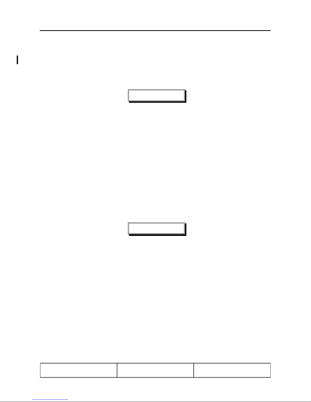
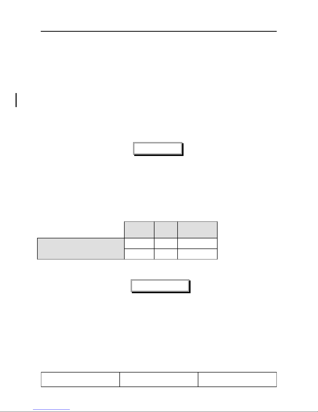
4.3 STRUCTURAL TEMPERATURE INDICATOR
A structural temperature indicator, installed on the spar bridge, indicates when the structural temperature
limitation is exceeded (ref. section 2.17). The indicator need only be checked if the OAT exceeds 38° C
(100° F).
The indicator is accessed by lifting the flap between the two seatback cushions. The indicator is visible
through the cut out in the seat shell backs (ref. fig. 2).
At temperatures below the 55° C (131° F) limit, the indicator appears all red with a faint indication of “55”
(° C). At temperatures exceeding the 55° C (131° F) limit, the indicator displays a clearly contrasting red
“55” (° C) on a black background (ref. fig.1).
NOTE
At temperatures approaching the limit, the background will progressively darken
prior to turning black; this indicates acceptable temperatures.
Red “55” on black background
indicates that structural temperature
limit is exceeded. Flight is prohibited.
All red indicates that structural
temperature is below limit. Flight is
permitted.
Figure 1
Doc # 202-100-VLA 20 December, 2000 Page
DOT Approved 4 - 3
Figure 2
Page 62

DIAMOND AIRCRAFT DA 20/100 Flight
Manual
[ INTENTIONALLY LEFT BLANK ]
Normal Operating Procedures
Doc # 202-100-VLA 20 December, 2000 Page
DOT Approved 4 - 4
Page 63

DIAMOND AIRCRAFT DA 20/100 Flight
Manual
4.4. NORMAL OPERATION CHECKLIST
4.4.1. Preflight Inspection
I. In-Cabin Check
Normal Operating Procedures
1. Structural Temperature Indicator
(if OAT exceeds 38°C (100° F))
2. Airplane Documents check
3. Flight Control Lock removed
4. Flight Controls check for proper direction of
5. Ignition Key pulled out
6. Carburetor Heat free, OFF
7. Cabin Heat free
8. Choke free, self-resetting
9. Parking Brake free
10. Throttle free, IDLE
11. Propeller Speed Control Lever free, max. RPM
12. Master Switch (Battery) ON
13. Warning Lights (Gen., Fuel Press., and Canopy) illuminated
14. Fuel Quantity sufficient
15. Engine Gauges, Ammeter and Voltmeter check
16. Circuit Breakers pressed in
17. Map Light operational
18. Instrument Lights operational and dimmable
19. Trim NEUTRAL
20. Wing Flaps (Indicator- and Flap Actuation) check, extend and retract fully
21. Trim and Flap Indicator Lights operational and dimmable
22. Exterior Lights operational as required
23. Master Switch (Battery) OFF
24. Foreign Object Inspection done
25. Emergency Locator Transmitter (ELT):
EBC Model 502 - ARM
EBC Model 102A - OFF
26. Fire Extinguisher check
27. Baggage stowed, baggage net attached
28. Canopy clean, undamaged
check that Structural Temperature
does not exceed 55° C (131° F)
movement
Doc # 202-100-VLA 20 December, 2000 Page
DOT Approved 4 - 5
Page 64

DIAMOND AIRCRAFT DA 20/100 Flight
Manual
II. Walk Around Check and Visual Inspection
Normal Operating Procedures
Doc # 202-100-VLA 20 December, 2000 Page
DOT Approved 4 - 6
Page 65

DIAMOND AIRCRAFT DA 20/100 Flight
Manual
CAUTION
Visually inspect for the following conditions: Defects, contamination, cracks,
delaminations, excessive play, insecure or improper mounting and general condition.
Additionally, check the control surfaces for freedom of movement.
CAUTION
Set PARKING brake prior to removing wheel chocks
1. Left Main Landing Gear
a) Landing Gear Strut visual inspection
b) Wheel Fairing visual inspection
c) Tire Pressure (33 psi / 2.3 bar) check
d) Tire, Wheel, Brake visual inspection
Normal Operating Procedures
e) Wheel Chocks remove
2. Left Wing
a) Entire Wing visual inspection
b) Stall Warning check (suck on opening)
c) Pitot-Static Probe clean, holes open
d) Tie down remove
e) Taxi and Landing Lights visual inspection
f) Wing Tip, Position Lights and Strobe visual inspection
g) Aileron Balancing Weight visual inspection
h) Aileron including Inspection Panel visual inspection
i) Wing Flap including Inspection Panel visual inspection
3. Fuselage
a) Skin visual inspection
b) Tank Vent check
c) Tank Drain drain water
d) Fuel Quantity visual inspection (use fuel pipette)
e) Antennas visual inspection
Doc # 202-100-VLA 20 December, 2000 Page
DOT Approved 4 - 7
Page 66

DIAMOND AIRCRAFT DA 20/100 Flight
Manual
4. Empennage
a) Stabilizers and Control Surfaces visual inspection
b) Tie down remove
c) Trim Tabs visual inspection
5. Right Wing
a) Entire Wing visual inspection
b) Wing Flap including Inspection Panel visual inspection
c) Aileron including Inspection Panel visual inspection
d) Aileron Balancing Weight visual inspection
e) Wing Tip, Position Lights and Strobe visual inspection
f) Tie down remove
6. Right Main Landing Gear
a) Landing Gear Strut visual inspection
b) Wheel Fairing visual inspection
c) Tire Pressure (33 psi / 2.3 bar) check
d) Tire, Wheel, Brake visual inspection
e) Wheel Chocks remove
Normal Operating Procedures
7. Nose
a) - Oil check level by using dip-stick.
min / max range is indicated by flat area
of stick
- Coolant Level must be between dip-stick
markings, refill if required.
b) Cowling visual inspection
c) Air Intakes (five) free
d) Propeller visual inspection, Ground Clearance;
minimum: approx. 25 cm (10 in).
e) Propeller Blades perform Pitch Check by Hand
f) Spinner visual inspection
g) Nose Gear visual inspection, towbar removed
h) Wheel Fairing visual inspection
i) Tire Pressure (26 psi / 1.8 bar) check
j) Tire and Wheel visual inspection
k) Wheel Chocks remove
Doc # 202-100-VLA 20 December, 2000 Page
DOT Approved 4 - 8
Page 67

DIAMOND AIRCRAFT DA 20/100 Flight
Manual
Normal Operating Procedures
4.4.2. Before Starting Engine
1. Preflight Inspection performed
2. Pedals adjust, lock
3. Passenger Briefing performed
4. Safety Belts fasten
5. Parking Brake set
6. Controls free
7. Fuel Shut-off Valve OPEN
8. Carburetor Heat OFF
9. Throttle IDLE
10. Propeller Speed Control Lever max. RPM
11. Friction Device of Throttle Quadrant adjust
12. Avionics Master Switch OFF
13. Master Switch (Battery/Generator) ON
14. Generator Warning Light illuminated
15. Fuel Pressure Warning Light illuminated
16. Exterior Lights as required
17. Instrument Panel Lighting as required
18. Canopy Close and Secure
19. Canopy Locking Warning Light OFF
NOTE
Under certain circumstances, activation of the fuel pressure warning light might take as
long as 10 minutes after shutting down the engine or switching off the electric fuel pump.
Doc # 202-100-VLA 20 December, 2000 Page
DOT Approved 4 - 9
Page 68

DIAMOND AIRCRAFT DA 20/100 Flight
Manual
Normal Operating Procedures
4.4.3. Starting Engine
NOTE
Extreme low temperatures require that the engine be preheated prior to engine start.
Satisfactory engine starts have been demonstrated at -31ºF (-35ºC) OAT after a 2 hour preheat with
the Tannis TAS100-27 preheat system.
1. Electric Fuel Pump ON (noise of pump audible)
2. Fuel Pressure Warning Light OFF
3. Throttle- Cold Start
- Warm Engine
4. Choke - Cold Start
- Warm Engine
5. Toe Brakes Hold
6. Propeller Area Clear
IDLE
approximately 3/4 in (2 cm)
forward
ON, fully pulled and hold
OFF
WARNING
Ensure that propeller area is clear!
7. Ignition Key START
NOTE
During extreme cold weather starts, hold the choke on until the engine starts to warm up.
8. Choke OFF
9. Throttle maximum 1500 RPM
10. Oil Pressure within green range after
maximum of 10 seconds
CAUTION
If Oil Pressure is below 12 psi (0.8 bar) shut down engine immediately (max. 10 seconds delay).
NOTE
Oil Pressure may advance to the yellow arc until Oil Temp. reaches normal operating temperatures.
NOTE
Activate starter for max. 10 sec. only, followed by a cooling period of 2 min.
11. Generator Warning Light OFF
12. Exterior Lights as required
13. Electric Fuel Pump OFF
Doc # 202-100-VLA 20 December, 2000 Page
DOT Approved 4 - 10
Page 69

DIAMOND AIRCRAFT DA 20/100 Flight
Manual
Normal Operating Procedures
4.4.4. Before Taxiing
1. Avionics Master Switch ON
2. Flight Instruments and Avionics set
3. Engine Gauges check
4. Voltmeter check, ensure needle is in the
green arc. Increase RPM to
achieve or turn OFF non-flight
essential electrical consumers
5. Warning Lights (Gen., Fuel Press., Canopy) push to test
6. Parking Brake release
CAUTION
Warm-up engine to a minimum Oil Temperature of 122° F (50° C) at 1100
to 1500 RPM (also possible during taxi).
4.4.5. Taxiing
1. Brake check
2. Direction Control check
3. Flight Instruments and Avionics check
4. Compass check
CAUTION
At high Propeller RPM the propeller may be damaged by loose sand, gravel or water.
Doc # 202-100-VLA 20 December, 2000 Page
DOT Approved 4 - 11
Page 70

DIAMOND AIRCRAFT DA 20/100 Flight
Manual
Normal Operating Procedures
4.4.6. Before Take-off (Engine Run-up)
NOTE
For OAT’s less than -5º F (-20º C) turn cabin heat on for at least 10 minutes prior to take-off.
1. Toe Brakes hold
2. Safety Belts fastened
3. Canopy closed and locked
4. Fuel Pressure Warning Light OFF (If light illuminates,
maintenance action is required and
flight should not be initiated )
5. Fuel Shut-off Valve check OPEN
6. Fuel Quantity Indicator check
7. Engine Gauges within green range
8. Trim NEUTRAL
9. Controls free
10. Throttle 1700-1800 RPM
11. Propeller Speed Control Lever Cycle 3 times
(RPM drop: 50 - 250 RPM)
12. Ignition Switch Cycle L - BOTH - R - BOTH
(Max. RPM drop: 150 RPM)
(Max. RPM difference (L/R): 50 RPM)
(Min. RPM difference (L/R): none, but
RPM drop must be noticeable)
13. Throttle 1500 RPM
14. Carburetor Heat ON
RPM drop: max. 50 RPM;
15. Throttle IDLE
16. Carburetor Heat OFF
17. Circuit Breakers check pressed IN
18. Electric Fuel Pump ON
19. Wing Flaps T/O
20. Parking Brake release
Doc # 202-100-VLA 20 December, 2000 Page
DOT Approved 4 - 12
Page 71

DIAMOND AIRCRAFT DA 20/100 Flight
Manual
4.4.7. Take-off
1. Electric Fuel Pump check ON
2. Master Switch (Battery/Generator) check ON
3. Ignition Switch check BOTH
4. Carburetor Heat check OFF
5. Wing Flaps check T/O
6. Propeller Speed Control Lever check max. RPM
Normal Operating Procedures
7. Throttle
Check RPM
8. Elevator - at beginning of rolling NEUTRAL
9. Directional Control maintain with rudder
FULL
2260 RPM to 2385 RPM
NOTE
In crosswind conditions, directional control can be enhanced by using the single wheel
brakes. Note that using the brakes for directional control increases the take-off roll
distance.
10. Rotate (v
11. Climb Speed (v
) 51 kts / 59 mph / 95 km/h
IAS
) 57 kts / 66 mph / 106 km/h
IAS
CAUTION
For the shortest possible take-off distance to clear a 15 m (50 ft) obstacle:
Lift-off Speed (v
Climb Speed (v
) 54 kts / 62 mph / 100 km/h
IAS
) 57 kts / 66 mph / 106 km/h
IAS
12. Propeller Speed Control Lever 2260 RPM
13. Electric Fuel Pump OFF
In order to avoid excessive noise, the propeller speed should be reduced to 2260 RPM as
Doc # 202-100-VLA 20 December, 2000 Page
DOT Approved 4 - 13
(after reaching safe height)
NOTE
soon as a safe flight altitude has been reached.
Page 72

DIAMOND AIRCRAFT DA 20/100 Flight
Manual
Normal Operating Procedures
4.4.8. Climb
1. Propeller Speed Control Lever 2260 RPM
2. Throttle FULL
3. Engine Gauges within green range
4. Wing Flaps T/O
5. Airspeed 65 kts / 75 mph / 120 km/h
6. Trim adjust
NOTE
The best rate of climb speed decreases with increasing altitude.
NOTE
Electric fuel pump ON above 13000 ft.
Speeds [ v
Altitude flaps T/O flaps UP
feet kts mph km/h kts mph km/h
0 - 4000 65 75 120 69 79 128
4000 - 7000 63 73 117 65 75 120
7000 -10000 62 71 115
above 10000 59 68 110
]
IAS
4.4.9. Cruise
1. Throttle as required
2. Propeller Speed Control Lever 1700 - 2260 RPM
NOTE
For favorable manifold pressure/RPM combinations refer to Chapter 5.
NOTE
3. Wing Flaps UP
4. Trim as required
5. Engine Gauges check
Doc # 202-100-VLA 20 December, 2000 Page
DOT Approved 4 - 14
Electric fuel pump ON above 13000 ft.
Page 73

DIAMOND AIRCRAFT DA 20/100 Flight
Manual
Normal Operating Procedures
4.4.10. Descent
1. Flight Instruments and Avionics adjust
2. Throttle as required
3. Propeller Speed Control Lever 1700 - 2260 RPM
4. Carburetor Heat as required
NOTE
To achieve a fast descent:
Propeller Speed Control Lever 2260 RPM
Throttle IDLE
Carburetor Heat ON
NOTE
If RPM drops and then rises, suspect carburetor icing and leave Carb Heat ON.
Otherwise turn Carb Heat OFF.
Wing Flaps UP
Airspeed 118 kts / 135 mph / 218 km/h
4.4.11. Landing Approach
1. Seat Belts fastened
2. Electric Fuel Pump ON
3. Lights as required
4. Master Switch (Battery/Generator) check ON
5. Ignition Switch check BOTH
6. Carburetor Heat ON
NOTE
If RPM drops and then rises, suspect carburetor icing and leave Carb Heat ON.
Otherwise turn Carb Heat OFF.
7. Throttle as required
8. Airspeed max. 81 kts / 93 mph / 150 km/h
9. Wing Flaps T/O
10. Trim as required
Doc # 202-100-VLA 20 December, 2000 Page
DOT Approved 4 - 15
Page 74

DIAMOND AIRCRAFT DA 20/100 Flight
Manual
11. Propeller Speed Control Lever max. RPM
12. Wing Flaps LDG
13. Approach Speed 57 kts / 66 mph / 106 km/h
Normal Operating Procedures
CAUTION
For strong headwind, crosswind, danger of wind-shear or turbulence, a higher approach
speed should be selected.
4.4.12. Balked Landing
1. Propeller Speed Control Lever max. RPM
2. Throttle FULL
3. Carburetor Heat OFF
4. Wing Flaps T/O
5. Airspeed 57 kts / 66 mph / 106 km/h
4.4.13. After Landing
1. Throttle as required
2. Wing Flaps UP
3. Carburetor Heat OFF
4. Exterior Lights as required
5. Electric Fuel Pump OFF
4.4.14. Engine Shut-down
1. Throttle IDLE
2. Parking Brake set
3. ELT Check (by listening to
121.5 MHZ for signal)
4. Avionics Master Switch OFF
5. Electric Consumers OFF
6. Ignition Switch OFF
7. Instrument Panel Lighting OFF
Doc # 202-100-VLA 20 December, 2000 Page
DOT Approved 4 - 16
Page 75

DIAMOND AIRCRAFT DA 20/100 Flight
Manual
8. Master Switch (Battery) OFF
9. Tie Downs and Wheel Chocks as required
Normal Operating Procedures
NOTE
In case of post ignition due to hot weather conditions, the ignition should
be switched on, choke pulled and after approximately 3 seconds, ignition
should be turned off again.
4.4.15.Flight in Rain
NOTE
Flight performance might be reduced, especially for the T/O-distance and the maximum horizontal air
speed. The influence on flight characteristics of the airplane is negligible. Flights through heavy rain
should be avoided due to the reduced visibility
Doc # 202-100-VLA 20 December, 2000 Page
DOT Approved 4 - 17
Page 76

DIAMOND AIRCRAFT DA 20/100 Flight Manual Performance
CHAPTER 5
PERFORMANCE
5.1 INTRODUCTION 5- 2
5.2 USE OF PERFORMANCE TABLES AND DIAGRAMS 5- 2
5.3 PERFORMANCE TABLES AND DIAGRAMS 5- 3
5.3.1 Figure 5.1: Airspeed Calibration 5- 3
5.3.2 Figure 5.2: Cruising Performance 5- 4
5.3.3 Figure 5.3: Stall Speeds 5- 5
5.3.4 Figure 5.4: Wind Data 5- 6
5.3.5 Figure 5.5: Take-Off Distances 5- 7
5.3.6 Figure 5.6: Climb Performance / Service Ceiling 5- 9
5.3.7 [INTENTIONALLY LEFT BLANK] 5-10
5.3.8 Figure 5.8: Cruising Speed (True Airspeed) 5-11
5.3.9 Figure 5.9: Maximum Flight Duration 5-12
5.3.10 Figure 5.10: Climb Performance during Balked Landing 5-13
5.3.11 Landing Distances 5-14
5.4
NOISE DATA 5-15
Doc # DA202-100-VLA March 19, 2004 Page
Revision 3 5 - 1
Page 77

DIAMOND AIRCRAFT DA 20/100 Flight Manual Performance
5.1. INTRODUCTION
The performance tables and diagrams on the following pages have been prepared to illustrate the
performance you may expect from your airplane as well as to assist you in precise flight planning. The
data presented in these tables and diagrams has been derived from test-flights using an airplane and
engine in good operating condition, and was corrected to standard atmospheric conditions [59° F (15° C)
and 29.92 in. Hg (1013.25 mbar) at sea level ].
The performance tables do not take into account the expertise of the pilot or the maintenance condition of
the airplane. The performance illustrated in the tables can be achieved if the indicated procedures are
followed and the airplane is in good maintenance condition.
Note that the flight duration data does not include a fuel reserve. The fuel consumption during cruise is
based on propeller RPM and manifold pressure settings. Some undefined variables such as the operating
condition of the engine, contamination of the aircrafts surface, or turbulence could have influences on
flight distance and flight duration. For this reason, it is of utmost importance that all available data is used
when calculating the required amount of fuel for a flight.
For flight operation without wheel fairings the resulting performance variations is given in %.
5.2. USE OF PERFORMANCE TABLES AND DIAGRAMS
The performance data is shown in the form of tables and diagrams to illustrate the influence of the
different variables. These tables contain sufficiently detailed information to plan any flight with the
necessary precision and safety on the conservative side.
Doc # 202-100-VLA 20 December, 2000 Page
Issue 1 5 - 2
Page 78

DIAMOND AIRCRAFT DA 20/100 Flight Manual Performance
[
]
]
5.3. PERFORMANCE TABLE AND DIAGRAMS
5.3.1. Figure 5.1: Airspeed System Calibration
Assumes zero indicator error
160
150
140
130
120
V
[kts
CAS
110
100
90
80
UP
70
T/O, LDG
60
50
40
40 50 60 70 80 90 100 110 120 130 140 150 160
V
kts
IAS
Example: v
Doc # 202-100-VLA 20 December, 2000 Page
DOT-Approved 5 - 3
= 93 kts equals v
IAS
= 95 kts.
CAS
Page 79

DIAMOND AIRCRAFT DA 20/100 Flight Manual Performance
5.3.2. Figure 5.2: Cruising Performance
Pressure
altitude
Ft. M
0 0 15 59 19 24.7 13.6 3.6 20 25.7 15.6 4.1
2000 600 11 52 19 24.0 14.4 3.8 20 24.7 16.0 4.2
4000 1200 7 45 19 23.3 15.6 4.1 21 23.3 16.8 4.4
6000 1800 3 38 20 22.0 16.8 4.4 22 22.7 19.6 5.2
8000 2400 -1 31 21 21.0 18.0 4.8 22 21.7 21.2 5.6
10000 3000 -5 24 22 19.7 19.2 5.1 22.6 20.3* 22.4* 5.9*
12000 3600 -8 17 22.6 18.0* 20.4* 5.4*
13000 4000 -11 12 22.6 17.0* 21.5* 5.7*
Standard
Temp.
°C °F
Engine power in % of maximum continuous power
55% 65%
Rpm
X100
MP
In.Hg
Fuel Flow Fuel Flow
L/hr
Gal/hr
Rpm
X100
MP
In.Hg
L/hr
Gal/hr
Pressure
altitude
Ft. M
0 0 15 59 21 27.0 18.0 4.8 22.6 27.7 22.0 5.8
2000 600 11 52 22 25.7 18.4 4.9 22.6 26.7 22.4 5.9
4000 1200 7 45 22.6 24.3 19.6 5.2 22.6 25.7* 25.2* 6.7*
6000 1800 3 38 22.6 23.3 23.2 6.1
8000 2400 -1 31 22.6 22.0* 23.6* 6.2*
Standard
Temp.
°C °F
Rpm
X100
75% 85%
MP
In.Hg
Fuel Flow Fuel Flow
L/hr
Gal/hr
Rpm
X100
MP
In.Hg
L/hr
Gal/hr
Pressure
altitude
Ft. M
0 0 15 59 22.6 28.3 26.0 6.9 23.8 29.7* 30.0 7.9*
2000 600 11 52 22.6 27.7* 26.8* 7.1*
4000 1200 7 45 22.6 25.7* 25.2* 6.7*
6000 1800 3 38
Standard
Temp.
°C °F
Maximum Continuous
Power
Rpm
X100
MP
In.Hg
Fuel Flow Fuel Flow
L/hr
Gal/hr
Maximum Take-Off Power
Rpm
X100
MP
In.Hg
L/hr
Gal/hr
Fuel flow is given in US-gal.
Data labelled * give a basis for interpolation. These values may not be attained at the stated altitude.
To maintain constant performance at non standard temperature gradient:
Raise manifold pressure by 0.7 in.Hg at ISA + 18° F (10° C)
Lower manifold pressure by 0.7 in.Hg at ISA - 18° F (10° C)
To keep engine wear to a minimum, engine operation below 1900 RPM is not recommended.
Doc # 202-100-VLA 20 December, 2000 Page
Issue 1 5 - 4
NOTE
Page 80

DIAMOND AIRCRAFT DA 20/100 Flight Manual Performance
5.3.3. Figure 5.3: Stall Speeds
Configuration:
Idle, most forward center of gravity, max. weight
(this is the most adverse configuration)
Stall speeds in kts
Bank Angle
Flaps 0° 30° 45° 60°
IAS CAS IAS CAS IAS CAS IAS CAS
UP 41 50 46 53 55 59 69 70
T/O 39 46 44 49 51 54 63 65
LDG 37 44 41 47 49 52 59 62
Stall speeds in mph
Bank Angle
Flaps 0° 30° 45° 60°
IAS CAS IAS CAS IAS CAS IAS CAS
UP 47 57 53 62 63 68 79 81
T/O 45 52 51 56 59 62 72 75
LDG 43 50 47 54 56 60 68 72
Stall speeds in km/h
Bank Angle
Flaps 0° 30° 45° 60°
IAS CAS IAS CAS IAS CAS IAS CAS
UP 76 93 85 99 101 109 127 130
T/O 72 84 81 91 94 100 117 120
LDG 69 81 76 87 91 96 109 115
Doc # 202-100-VLA 20 December, 2000 Page
DOT-Approved 5 - 5
Page 81

DIAMOND AIRCRAFT DA 20/100 Flight Manual Performance
5.3.4. Figure 5.4: Wind Components
Maximum demonstrated crosswind component: 15 kts (27 km/h)
Example:
Wind speed: 11 kts (20 km/h)
Angle between wind direction and flight direction: 30°
Headwind component: 9.5 kts (18 km/h)
Crosswind component: 5.5 kts (10 km/h)
Doc # 202-100-VLA 20 December, 2000 Page
DOT-Approved 5 - 6
Page 82

DIAMOND AIRCRAFT DA 20/100 Flight Manual Performance
5.3.5. Figure 5.5: Take-off Distance
Conditions:
- maximum take-off power
- lift-off speed 53 KIAS and speed for climb over obstacle 57 KIAS
- level runway, paved
- Wing Flaps in Take-Off Position (T/O)
-4 14 32 50 68 86 104
t
f
0
00
12
=
p
H
S
t
d
T
e
m
p
t
f
0
0
0
0
1
=
p
H
t
f
0
0
0
8
=
p
H
t
f
0
0
0
6
=
p
H
t
f
0
0
0
4
=
p
H
t
f
0
0
0
2
=
p
H
t
f
0
=
p
H
t
f
0
0
0
2
-
=
p
H
Ouside Air Temperature (°F)
-20-100 10203040
Ouside Air Temperature (°C)
Airc ra ft W e ig h t (lb s.)
1653 1598 1543 1488 1433 1378 1323
Aircraft Weight (kg)
600625650675700725750
0 5 10 15 20
Headwind Component (knot)
Ob s ta c le He ig h t (f e e t)
.
0163349
0 5 10 15
Obstacle Height (m )
(feet )
3500
3300
3100
2900
2700
2500
2300
2100
1900
1700
1500
1300
1100
900
700
500
(m )
1052
952
852
752
652
552
Takeoff Distance
452
352
252
152
.
(m )(feet )
Example: - Pressure altitude: 3000 ft
- Outside temperature: 15° C (59° F)
- Weight : 1598 lbs (725 kg)
-Headwind: 10 kts
Result: - Take-off roll distance: 1025ft (312.4 m)
- Take-off distance to clear a 15 m (50 ft) obstacle: 1425 ft (434.3 m)
NOTE
Poor maintenance condition of the airplane, deviation from the given procedures as well as
unfavourable outside conditions (high temperature, rain, unfavourable wind conditions, including
cross-wind) could increase the take-off distance considerably.
For take-off from dry, short-cut grass covered runways, the following corrections must be taken
into account, compared to paved runways:
Doc # DA202-100-VLA March 19, 2004 Page
Revision 3 5 - 7
Page 83

DIAMOND AIRCRAFT DA 20/100 Flight Manual Performance
• Grass up to 5cm (2in) deep: 10% increase in take-off roll distance;
• Grass 5 to 10cm (2 to 4in) deep: 15% increase in take-off roll distance;
• Grass deeper than 10cm (4in): 25% increase in take-off roll distance.
On wet soft grass covered runways with grass deeper than 10cm (4in), the take-off roll distance
might be increased by as much as 40%.
This information is provided for guidance purposes only and has not been demonstrated.
The dashed lines in the above diagram (wind component) represent tailwind.
Doc # DA202-100-VLA March 19, 2004 Page
Revision 3 5 - 8
Page 84

DIAMOND AIRCRAFT DA 20/100 Flight Manual Performance
5.3.6. Figure 5.6 : Climb Performance / Service Ceiling
Service Ceiling (in standard conditions): 17600 ft (5365 m)
Best Rate-of-Climb Speed with Wing Flaps in Take-Off Position (T/O): 65 kts / 75 mph / 120 km/h
TEMPERA TURE (°F)
-4 5 142332415059687786
18000
16000
Standard Temperature
14000
12000
10000
8000
6000
PRESSURE ALTITUDE (FEET)
4000
2000
0
-2000
-20-15-10-5 0 5 1015202530
TEMPERA TURE (°C)
0.5 1.0 1.5 2.0 2.5 3.0 3.6 4.1 4.6 5.1
16000
14000
12000
10000
8000
6000
4000
2000
0
100 200 300 400 500 600 700 800 900 1000
m/sec
1433 lbs / 650 kg
1543 lbs / 700 kg
1609 lbs / 730 kg
1653 lbs / 750 kg
RO C (ft/min)
Example: Pressure Altitude: 5000 ft (1524 m)
OAT: 46° F (8° C)
Weight : 1477 lbs (670 kg)
Result: Climb performance: 554 ft/min (2.82 m/s)
In case of operation without wheel fairings the climb performance is reduced by approximately 3%.
Doc # DA202-100-VLA March 19, 2004 Page
Revision 3 5 - 9
CAUTION
Page 85

DIAMOND AIRCRAFT DA 20/100 Flight Manual Performance
5.3.7. [INTENTIONALLY LEFT BLANK]
[ INTENTIONALLY LEFT BLANK ]
Doc # DA202-100-VLA March 19, 2004 Page
Revision 3 5 - 10
Page 86

DIAMOND AIRCRAFT DA 20/100 Flight Manual Performance
5.3.8. Figure 5.8: Cruising Speed (True Airspeed)
Diagram for true airspeed (TAS) calculation at selected power level.
Flight mass 750 kg (1653 lbs) and Flaps UP.
Temperature (°F)
-
Temperature (°C)
Example: Pressure altitude: 9500 ft
Temperature: 57° F (14° C)
power setting: 55 %
Result: True airspeed (TAS): 116 kts (215 km/h)
True Airspeed (knots)
CAUTION
In case of operation without wheel fairings the maximum cruising speed is reduced by
approximately 5%.
Doc # DA202-100-VLA March 19, 2004 Page
Revision 3 5 - 11
Page 87

DIAMOND AIRCRAFT DA 20/100 Flight Manual Performance
5.3.9. Figure 5.9: Maximum Flight Duration
Diagram for calculation of the maximum flight duration depending on fuel availability.
Flight Time (hour), 45 minute reserve
- 3/4 1/4 1 1/4 2 1/4 3 1/4 4 1/4 5 1/4
80
75 %
f
.
t
t
f
t.
0
2
1
f
0
0
0
0
0
0
2
4
/
/
m
0
0
0
6
0
m
8
1
.
0
0
0
6
/
m
m
0
0
0
2
1
55 %
.
t
.
f
t
.
t
0
f
0
0
0
0
4
0
/
2
/
m
0
0
6
70
60
50
95 %
.
t
f
0
0
0
2
/
m
0
0
6
80
1
f
00
0
/ 6
m
0
20
18
16
14
12
40
30
10
8
Fuel Quantity (litres)
6
20
4
10
2
0
0
0123456
Flight Time (hour), no reserve
Example: Fuel quantity: 13.2 US gal (50 liters)
Pressure Altitude 6000 ft
Power Setting: 75%
Fuel Quantity (US Gal)
Result: Possible flight time
Possible flight time
Doc # DA202-100-VLA March 19, 2004 Page
Revision 3 5 - 12
without reserve: 2:11 h:min
with reserve of 45 mins: 1:26 h:min
Page 88

DIAMOND AIRCRAFT DA 20/100 Flight Manual Performance
)
5.3.10. Figure 5.10: Climb Performance during Balked Landing
Conditions: Speed = 57 kts / 66 mph / 106 km/h
Wing Flaps in Landing Position (LDG)
Weight 750 kg (1653 lbs)
most forward center of gravity
max take-off power
800
4.06
700
3.56
600
500
3.05
2.54
400
ROC (ft/min)
300
200
2.03
ROC ( m/sec)
1.52
1.02
100
0.51
0
0 1000 2000 3000 4000 5000 6000 7000 8000 9000 10000
0.00
Hp (ft)
Hp (m
Example: Pressure altitude: 2250 ft (685 m)
Outside temperature: 59° F (15° C)
Result: Climb performance during balked landing: 320 ft/min. (1.63 m/sec)
In case of operation without wheel fairings the climb performance is reduced by
approximately 3%.
Doc # DA202-100-VLA March 19, 2004 Page
Revision 3 5 - 13
CAUTION
Page 89

DIAMOND AIRCRAFT DA 20/100 Flight Manual Performance
5.3.11. Landing Distance
Conditions: - Throttle: Idle
- Maximum T/O Weight
- Propeller Speed Control Lever: max RPM
- Approach Speed 57 kts / 66 mph / 106 km/h
- Level Runway, paved
- Wing Flaps in Landing position (LDG)
- Standard Setting, MSL
Landing distance over a 15 m (50 ft) obstacle: approx. 1532 ft (467 m)
Landing roll distance: approx. 790 ft (241 m)
Figure 5.11: Landing and Rolling Distances for Heights Above MSL
Height above MSL ft.
(m)
0
(0)
1000
(305)
2000
(610)
3000
(914)
4000
(1219)
5000
(1524)
Landing Distance
Landing Roll Distance ft.
ft.
(m)
(m)
1532
(467)
790
(241)
1593
(486)
813
(248)
1653
(504)
837
(255)
1714
(522)
862
(263)
1775
(541)
889
(271)
1836
(560)
916
(279)
NOTE
Poor maintenance condition of the airplane, deviation from the given procedures as well as
unfavourable outside conditions (high temperature, rain, unfavourable wind conditions, including
cross-wind) could increase the landing distance considerably.
For landings on dry, short-cut grass covered runways, the following corrections must be taken
into account, compared to paved runways:
• Grass up to 5cm (2in) deep: 5% increase in landing roll distance;
• Grass 5 to 10cm (2 to 4in) deep: 15% increase in landing roll distance;
• Grass deeper than 10cm (4in): 25% increase in landing roll distance.
On wet soft grass covered runways with grass deeper than 10cm (4in), the landing roll distance might be
increased by as much as 40%.
This information is provided for guidance purposes only and has not been demonstrated.
Doc # DA202-100-VLA March 19, 2004 Page
Revision 3 5 - 14
Page 90

DIAMOND AIRCRAFT DA 20/100 Flight Manual Performance
5.4 NOISE DATA
a) Noise limit according to FAR 36, Appendix G: 75.0 dB (A)
Noise value measured: 63.8 dB (A)
b) Noise limit according to ICAO Annex 16, Chapter 10: 79.1 dB (A)
Noise value measured: 71.7 dB (A)
Doc # DA202-100-VLA March 19, 2004 Page
Revision 3 5 - 15
Page 91

DIAMOND AIRCRAFT DA 20/100 Flight Manual Weight & Balance
CHAPTER 6
WEIGHT AND BALANCE / EQUIPMENT LIST
6.1 INTRODUCTION 6-2
6.2 AIRPLANE WEIGHING 6-3
- Figure 6.1 Weighing Report 6-4
6.3 WEIGHT AND BALANCE REPORT 6-5
- Figure 6.2 Weight & Balance Report 6-6
6.4 FLIGHT-WEIGHT AND CENTER OF GRAVITY 6-7
- Figure 6.3 Weight & Balance Diagram 6-8
- Figure 6.4 Calculation of Loading Condition 6-9
- Figure 6.5 Permissible Center of Gravity Range and
permissible Flight Weight-Moment
6.5 EQUIPMENT LIST 6-11
6-10
AIRCRAFT SPECIFIC WEIGHT AND BALANCE DOCUMENTS
(ENCLOSED AT THE END OF THIS CHAPTER)
Doc # 202-100-VLA 20 December, 2000 Page
DOT-Approved 6 - 1
Page 92

DIAMOND AIRCRAFT DA 20/100 Flight Manual Weight & Balance
1. INTRODUCTION
To obtain the performance, flight characteristics and safe operation described in this Flight Manual, the
airplane must be operated within the permissible weight and balance envelope as described in Chapter 2.
It is the pilot's responsibility to adhere to the weight and balance limitations and to take into consideration
the change of the CG position due to fuel consumption.
The procedure for weighing the airplane and calculating the empty weight CG position are given in this
Chapter.
The aircraft is weighed when new and should be reweighed in accordance with applicable air regulations.
Empty weight and the center of gravity are recorded in a Weighing Report and Weight and Balance
Report as illustrated in the samples in figure 6.1 and 6.2. The actual report for the aircraft is at the end of
this chapter.
In case of equipment changes, the new weight and empty weight CG position must be determined by
calculation or by weighing and must be entered in the Weight & Balance Report. The following pages are
sample forms which can be used for airplane weighing, calculation of the empty weight CG position, and
for the determination of the useful load.
NOTE
After every repair, painting or change of equipment the new empty weight must be
determined as required by applicable air regulations. Weight, empty weight CG position
and useful load must be entered in the Weight & Balance Report by an authorized
person.
Doc # 202-100-VLA 20 December, 2000 Page
DOT-Approved 6 - 2
Page 93

DIAMOND AIRCRAFT DA 20/100 Flight Manual Weight & Balance
6.2. AIRPLANE WEIGHING
Pre-weighing conditions:
- equipment must be in accordance with the airplane equipment list
- brake fluid, lubricant (3.17 US qt / 3 liters), coolant (2.64 US qt / 2,5 liters) and
unusable fuel (0.53 US gal./ 2 liters), included
To determine the empty weight and the empty weight CG position, the airplane is to be positioned in the
above mentioned pre-weighing condition, with the nose gear and each main gear on a scale. Ensure the
aircraft is level longitudinally as illustrated on the weighing report (see figure 6.1).
With the airplane correctly positioned, a plumb line is dropped from the leading edge of each wing at the
root rib to the floor, join these two points to determine the reference datum (RD). From this line use a
suspended plumb line aligned with each landing gear to measure the distances D
main gear) and D
(right main gear).
R
(nose gear), DL (left
N
The following formulas apply:
Empty Weight: W
Empty Weight Moment: M = W
Empty Weight CG position : =
= WN + WL + WR lbs [kg]
T
x DN + WL x DL + WR x DR in⋅lbs [m⋅kg]
N
Empty Weight Moment
Empty Weight
M
= in [m]
W
T
CAUTION
Items ahead of RD are considered to have a negative lever arm.
Items aft of RD are considered to have a positive lever arm.
Record the data in the Weighing Report included at the end of this chapter. The following
Sample Weighing Report figure 6.1 is for reference only.
Doc # 202-100-VLA 20 December, 2000 Page
DOT-Approved 6 - 3
Page 94

DIAMOND AIRCRAFT DA 20/100 Flight Manual Weight & Balance
Figure 6.1: Sample Weighing Report (Aircraft Specific report at the end of this chapter.)
Model:
DA 20/100
Data in accordance with TCDS and Flight Manual Reason for Weighing:
Reference Datum: Leading edge of wing at root rib
Horizontal reference line: 24” Spirit Level placed on Fuselage Canopy Rail (L or R), supported at front by a
2 1/4” spacer as shown below
Weighing Conditions: including brake fluid, lubricant, coolant and unusable fuel (3.31 lbs/1.5 kg)
Equipment List dated:
S/N: Registration:
Support Gross
[lbs] ([kg])
Tare
[lbs] ([kg])
Net Weight
[lbs] ([kg])
Lever Arm
[in] ([m])
Nose WN = DN =
Main Left WL = DL =
Main Right WR = DR =
Empty Weight WT = WN + WL + WR = lbs (kg)
Empty Weight Moment M = WN x DN + WL x DL + WR x D
Empty Weight CG Position
Empty Weight Moment
Empty Weight
(Positive results indicate, that CG is located aft of RD)
M
=
W
T
= _________________
R
= _________________
Maximum Permissible Useful Load: Maximum Weight [lbs] ([kg])
Empty Weight [lbs] ([kg])
+
−
in lbs [m kg]
in [m]
Max useful Load [lbs] ([kg]) =
Data to be entered into the Flight Manual: see page 6-6
Empty Weight [lbs] ([kg])
Empty- Weight-Moment [in⋅lbs] ([kg⋅m])
Place / Date
Inspector’s Stamp Inspector’s Signature
Doc # 202-100-VLA 20 December, 2000 Page
DOT-Approved 6 - 4
Page 95

DIAMOND AIRCRAFT DA 20/100 Flight Manual Weight & Balance
6.3. WEIGHT AND BALANCE REPORT
The empty weight and Empty Weight CG position data determined prior to delivery of the airplane is the
first entry in the Weight and Balance Report. Each change of the installed equipment as well as each
repair affecting the empty weight, the CG position of the empty weight or the empty weight moment must
be entered in the Weight and Balance Report at the end of this chapter. The following Sample Weight
and Balance Report figure 6.2. is for reference only.
Ensure that you are using the latest weight and balance information when performing a weight and
balance calculation
Doc # 202-100-VLA 20 December, 2000 Page
Issue 1 6 - 5
Page 96

DIAMOND AIRCRAFT DA 20/100 Flight Manual Weight & Balance
T
A
figure 6.2: Sample Weight and Balance Report (Aircraft specific report at the end of this chapter)
Model: DA20-A1/100 KATANA
Aircraft Specific Weight and Balance Report
Date Description Changes of W eight Actual Signature
IN OU
of Part or Addition (+) Subtraction (-) Empty Weight
Modification Weight Arm Moment W eight Arm Moment Weight Arm Moment
Original
lbs in in.lbs lbs in in .lbs lbs in in.lbs
(kg) (m ) (kg.m) (kg) (m) (kg.m) (kg) (m) (kg.m)
ircraft Serial No.:
Registration:
Issue Date:
Doc # 202-100-VLA 20 December, 2000 Page
Issue 1 6 - 6
Page 97

DIAMOND AIRCRAFT DA 20/100 Flight Manual Weight & Balance
6.4. FLIGHT WEIGHT AND CENTER OF GRAVITY
The following data enables the pilot to operate the DA 20/100 within the required weight and center of
gravity limitations.
The following diagrams,
Figure 6.3 Weight & Balance Diagram
Figure 6.4 Calculation of Loading Condition
Figure 6.5 Permissible Center of Gravity Range
and permissible Flight-
are to be used for calculations of the flight-weight and the center of gravity as follows:
1. The empty weight and the empty-weight-moment of the airplane should be taken from the
weighing report or from the weight & balance report and entered into the form "Calculation of
Loading Condition" (figure 6.4) in the columns identified with "Your DA 20".
2. Using the Weight & Balance Diagram (see figure 6.3) determine the moment for each part to be
loaded, and enter it in the respective column in figure 6.4.
3. Add the weights and the moments of each column (point 4 and point 6 in figure 6.4) and enter the
sum in figure 6.5 "Permissible CG Range and Permissible Flight-Weight-Moment" to check if the
values are within the permissible limits of the loading range.
Weight-Moment
Doc # 202-100-VLA 20 December, 2000 Page
DOT approved 6 - 7
Page 98

DIAMOND AIRCRAFT DA 20/100 Flight Manual Weight & Balance
Figure 6.3: Weight & Balance Diagram
Example: Pilot and Passenger: 380 lbs. (172 kg)
Fuel 19.5 US gal. / 74 liters: 117 lbs. ( 53 kg)
(6.01 lbs. per US gal./0.72 kg per liter)
Baggage 11lbs. (5 kg)
Result: Moment of Pilot and Passenger: 2139 in.lbs. (24.60 kgm)
Moment of Fuel: 3796 in.lbs. (43.76 kgm)
Moment of Baggage 357 in.lbs. (4.12 kgm)
Doc # 202-100-VLA 9 March, 2001 Page
DOT-Approved 6 - 8
Page 99

DIAMOND AIRCRAFT DA 20/100 Flight Manual Weight & Balance
Figure 6.4: Calculation of Loading Condition
Calculation of the
Load Limits
(Weight [kg]) ([kgm]) (Weight [kg]) ([kgm])
1. Empty Weight (use the data for
your airplane recorded in the
equipment list, including unusable
fuel, lubricant and coolant).
2. Pilot and Passenger:
Lever Arm: 0.143 m (5.63 in)
3. Baggage:
Lever Arm: 0.824 m (32.44 in)
DA 20 (Example) Your DA 20
Weight [lbs] Moment
[in.lbs]
1145
(520)
380
(172)
11
(5)
12880
(148.40)
2139
(24.60)
357
(4.12)
Weight [lbs] Moment
[in.lbs]
4. Total Weight and Total Moment
with empty fuel tank (sum of 1. - 3.)
5. Usable Fuel Load
(6.01 lbs. per US gal./0.72 kg per liter)
Lever Arm (32.44 in) (0.824 m)
6. Total Weight and Total Moment,
taking fuel into account
(sum of 4. and 5.)
7. Find the values for the total weight (1536 lbs. and 1653 lbs.) and the total moment (15376 in lbs.
and 19172 in.lbs.) in the center of gravity diagram. Since they are within the limitation range, the
loading is permissible.
1536
(697)
117
(53)
1653
(750)
15376
(177.12)
3796
(43.76)
19172
(220.88)
Doc # 202-100-VLA 9 March, 2001 Page
DOT-Approved 6 - 9
Page 100

DIAMOND AIRCRAFT DA 20/100 Flight Manual Weight & Balance
Figure 6.5: Permissible Center of Gravity Range and permissible Flight-Weight-Moment
1653 --
1635
1585
1535
1485
1435
1385
Flight Weight [lbs.]
1335
1285
Permissible Center of Gravity Range [mm/in]
)
m
m
0
5
2
(
"
8
.
9
1
1
)
m
m
0
7
2
(
"
6
.
0
1
)
m
m
0
9
2
(
"
4
.
1
1
)
m
m
0
1
3
(
'
2
.
2
)
m
m
0
3
3
(
"
0
.
3
1
1
)
m
m
0
5
3
(
"
8
.
3
1
)
m
m
0
7
(3
"
5
.
4
5
1
--750
)
m
m
0
9
3
(
"
5
3
.
735
710
685
660
635
Flight Weight [kg.]
610
585
1235
12100 13428 14756 16084 17412 18740 20068 21396 22724 24052 25380
Permissable Flight-Weight-Moment
DA 20 (Example of page 6-9)
Changes during flight (due to fuel consumption)
1
560
(in*lbs)
(Kg*m)
Doc # 202-100-VLA November 18, 2003 Page
Revision 2 6 - 10
 Loading...