

Page 1
Mod: PSB-130/2
Production code: ZZIS1304053F
06/2012
Page 2
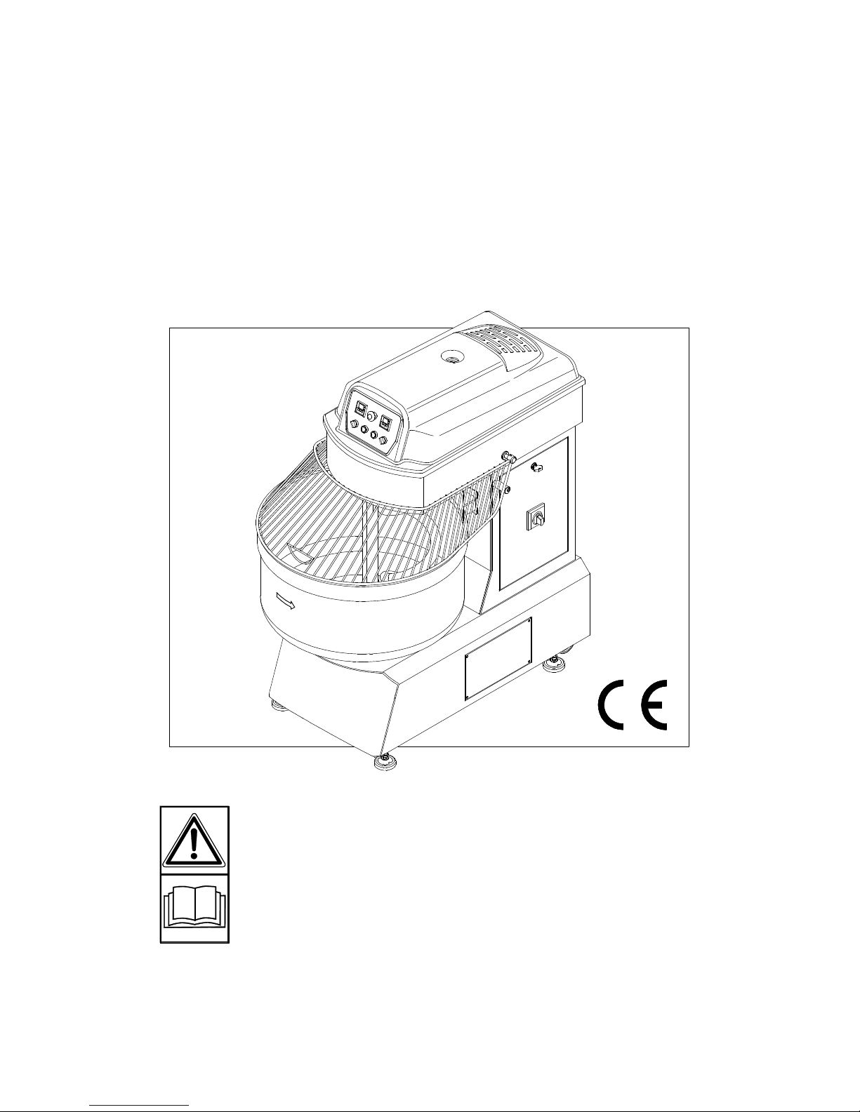
DOUGH MIXER
IRIS
OPERATING AND
MAINTENANCE
MANUAL
Rev.001 01-06-2012
Read the
instruction
manual
carefully
before
beginning
to work
with the
machine
Page 3

INDEX
SECTION 1: Description and Main
specifications
1.1 Presentation ....................................................3
1.2 Warranty ............................................................ 3
1.2.1 Warranty exclusions ..............................3
1.3 Description of the machine and use ................3
1.3.1 Use .........................................................5
1.3.2 Description ............................................5
1.3.3 Safety devices ........................................5
1.4 Identification ....................................................6
1.5 Noise level .......................................................6
1.6 Technical specifications ..................................6
SECTION 2: General safety rules
2.1 Safety ..........................................................8
2.1.1 Terminology used ..................................8
2.2 Safety decals ...................................................8
2.3 Clothing ..........................................................9
2.4 Ecology and pollution ....................................10
2.5 Safe use of the machine ................................10
2.6 Safe maintenance ..........................................10
SECTION 3: Transport and installation
3.1 Transport ............................................................ 11
3.2 Installation ......................................................11
3.2.1 Positioning ...........................................12
3.2.2 Electrical connection ............................12
3.3 General inspection .........................................12
SECTION 4: Instructions for use
4.1 Prior to use ....................................................13
4.1.1 Control panel (80-250) ........................13
4.1.2 Control panel (30-40) ..........................13
4.2 Use .........................................................13
4.2.1 How to start the dough mixer ..............14
4.2.2 How to take product from the bowl ......14
4.3 Emergency stop .............................................15
4.4 Cleaning after use ..........................................15
SECTION 5: Maintenance
5.1 Routine maintenance .....................................16
5.2 Belt transmission ...........................................16
5.2.1 Dough tool transmission ......................17
5.2.2 Bowl transmission ................................17
5.3 Storage .........................................................18
5.4 Troubleshooting .............................................19
SECTION 6: Spare parts
6.1 How to order spare parts …………………… ......21
6.2 Spare parts tables ..............................................21
Dati riportati nella targhetta di identificazione della macchina
Model
Year of manufacture
Serial number
Delivery date of machine
Manifacturer
Page 4

_______________________________
DOUGH
MIXER IRIS
_______________________________
3
SECTION 1
Description and main specifications
1.1 PRESENTATION
This manual contains the instructions and every
indication considered necessary for correctly
using and servicing the mod. «IRIS» dough
mixer, also called machine in the following text,
manufactured by
………………………………………………………
………….., also called Manufacturer in the text.
The information given in the manual does not
constitute a complete description of the various
components nor a detailed illustration of the way
they operate. However, the user will find
everything he normally needs to know for safe
use and correct care of the machine. Regular,
long-lasting operation and economic running of
the machine depend on compliance with the
instructions given in this manual as does careful,
regular maintenance.
WARNING
Failure to comply with the instructions given
in this manual will oblige the Manufacturer to
void the warranty provided with the machine.
If repairs or overhauls involving fairly complex
operations are required, contact the
Manufacturer where there are technicians able to
provide prompt and accurate technical
assistance.
1.2 WARRANTY
The Manufacturer guarantees its brand-new
products for a period of 24 (twenty-four) months
from the date of purchase. As soon as you
receive the machine, check to make sure that it
is in a perfect condition and complete.
Complaints must be presented in writing within 8
(eight) days from the date on which the actual
machine is received. The warranty solely covers
the repair or replacement, free of charge, of
those parts which, after having been carefully
examined by the manufacturer’s technical
department, are recognized as being defective
(excluding the electrical parts).
Repairs or replacement of parts under guarantee
will in no case extend the warranty terms.
However, the purchaser is only entitled to repairs
or replacements under guarantee if he has
complied with any other conditions concerning
warranty performance indicated in the contract of
supply.
1.2.1 WARRANTI EXCLUSIONS
The warranty also becomes void (besides in
the cases indicated in the contract of supply):
- When there have been incorrect
manoeuvres ascribable to the operator;
- When the damage has been due to
insufficient maintenance;
- When, following repairs carried out by
the user without the Manufacturer’s consent
or owing to the use of spurious spare parts,
the machine has been modified and the
damage is ascribable to these modifications;
- If the instructions in this manual have
not been complied with;
Damages caused by negligence,
carelessness, bad use and incorrect use of
the machine are also not covered by the
warranty.
Removal of the safety devices with which the
machine is equipped will automatically void
the warranty and relieve the Manufacturer
from all deriving liability.
If the machine or parts of it are returned, they
must be shipped CARRIAGE PAID even when
the Manufacturer’s warranty is still valid.
1.3 DESCRIPTION OF THE MACHINE
AND USE
The mod. «IRIS» dough mixer is a machine that
bears «CE» marking, in compliance with
Annexes «I» and «IV» of directive 2006/42CE
and directive 2006/95/CE - 93/68/CEE
concerning the electrical components, as
specified in the declaration of conformity with
which every machine is supplied.
Page 5
_______________________________
DOUGH
MIXER IRIS
_______________________________
4
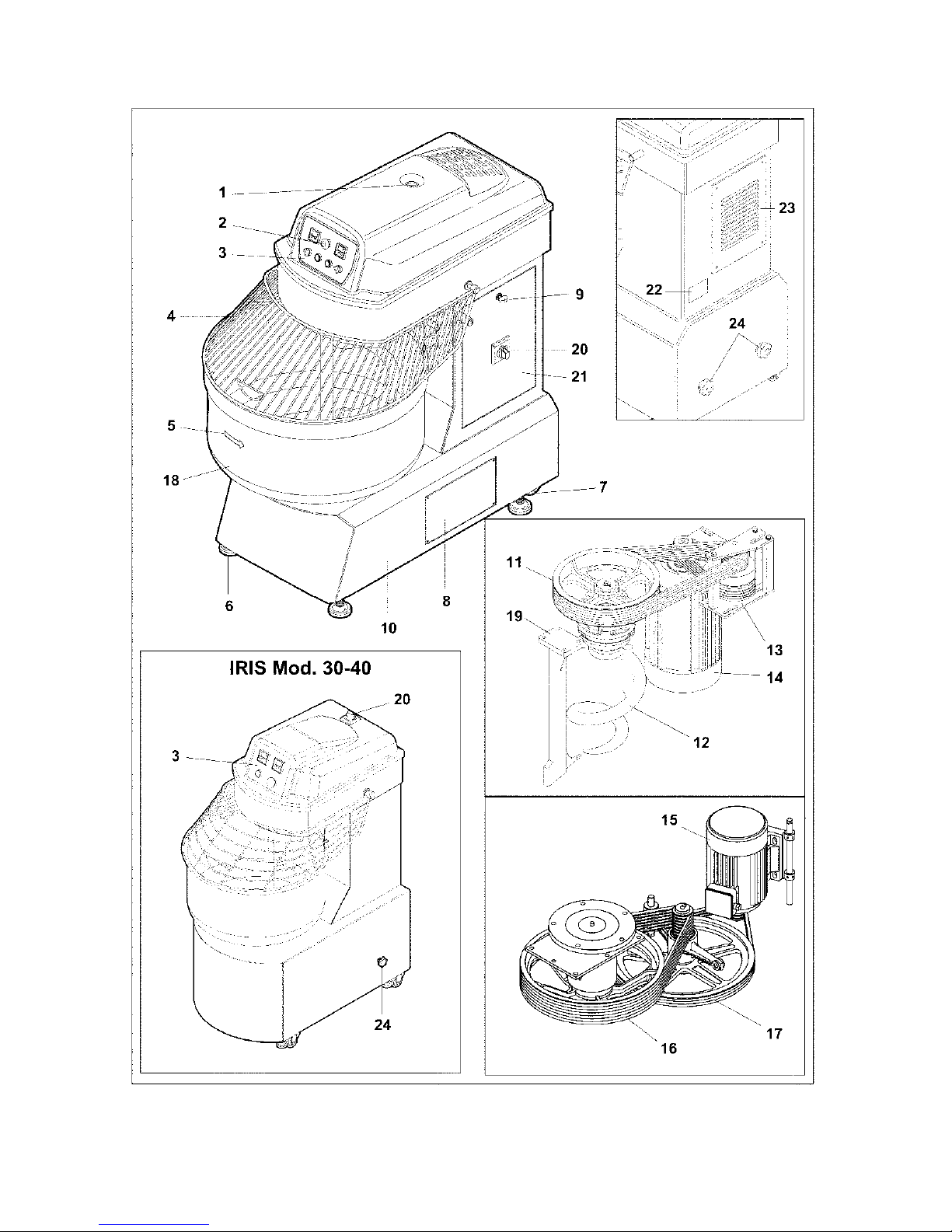
Fig. 1 - Overall view of the machine and main components
KEY Fig. 1 1) Upper cover fixing screw;
Page 6

_______________________________
DOUGH
MIXER IRIS
_______________________________
5
2) Emergency stop button;
3) Control panel (consult «4.1.1 Control
panel» for the relative description);
4) Protective grille;
5) Bowl;
6) Adjustable feet (4) to allow the machine
to stand in a stable way on the floor;
7) Wheels for moving the machine;
8) Side inspection panel;
9) Lock with key;
10) Bearing structure of the machine;
11) Upper pulley to control dough tool;
12) Dough tool;
13) Dough tool transmission unit;
14) Upper electric motor for controlling
dough tool;
15) Lower electric motor for controlling bowl
rotation;
16) Lower pulley for controlling bowl;
17) Bowl transmission unit;
18) Arrow indicating bowl rotation direction;
19) Shaft.
20) Main switch with door lock;
21) Door for accessing the electric panel;
22) Position of identification plate.
23) Rear inspection panel;
24) Lower belt tensioning knobs.
1.3.1 USE
The mod. «IRIS» dough mixer has been
exclusively designed for the use of mixtures of
various types of flour available on all the
international markets, in authorized work
environments and small industries such as:
bakeries, pizza restaurants and confectioners’
shops.
1.3.2 DESCRIPTION
(The numbers between brackets refer to Fig.1).
The machine mainly consists of a robust metal
bearing structure (10) equipped with two drive
units: an upper one (14), which turns the dough
tool. and a lower one (15), which drives the
bowl (18). The rotational movement of the IRIS
30-40 dough mixer is controlled by a single
motor. The electric panel is situated under the
upper cover, which also closes and protects
the machine. In both the drive units, the actual
drive is transmitted by V-belts, the tension of
which is regulated by belt stretchers. The
dough mixer’s functions are controlled by a
control panel (3), which is described in section:
«4.1.1 Control panel».
The work cycle can be programmed by means
of two timers, which allow the dough mixer to
automatically switch from the first to the second
speed. The bowl can be turned at first speed by
means of a selector, i.e.: NORMAL (anticlockwise direction), REVERSE (clockwise
direction), or bowl at a standstill. Drive reversal is
not available for version 30-40, thus the relative
selector is not installed. During the first phase,
the ingredients are mixed together so as to obtain
a homogeneous dough. As the consistency of the
mixture and the speed of the dough tool increase,
the dough is finished and fully blended in the
second phase. At the end of the process, the
operator can switch the selector to the reverse
rotation position (opposite to the direction of the
normal cycle, i.e. clockwise) to detach the dough
from the dough tool while bringing it to the center
of the bowl so that it can be easily cut and
removed.
WARNING
The Manufacturer declines all liability for
direct and indirect damages to persons,
animals or property caused by the machine
having been used for purposes other than
those described in this manual (see 1.3.2
Use).
1.3.3 SAFETY DEVICES
WARNING
The electrical system of this machine has
been built in compliance with the current
standards, particularly standard EN 60204-01.
The electrical system is equipped with a device
that protects against overloads and includes a
thermic relay and protective fuses (consult the
wiring diagram supplied separately).
To safeguard the operator, the grille (4) prevents
the limbs from accidentally accessing the bowl
interior when the dough tool is turning. The bowl
and dough tool will immediately stop if this grille is
raised when the machine is running. The electric
panel is also protected by a key-operated lock. In
versions 80-250, the access door has a keyoperated lock (9) and a main switch (20) with
Page 7
_______________________________
DOUGH
MIXER IRIS
_______________________________
6
door lock, i.e. it cannot be opened when the
machine is powered.
Protection is guaranteed for the 30-40 version
by the closing system of the upper cover with
main switch and the nut that closes the actual
cover itself. Lastly, the entire machine cycle will
immediately stop if the red stop button (2) on
the control panel is pressed.
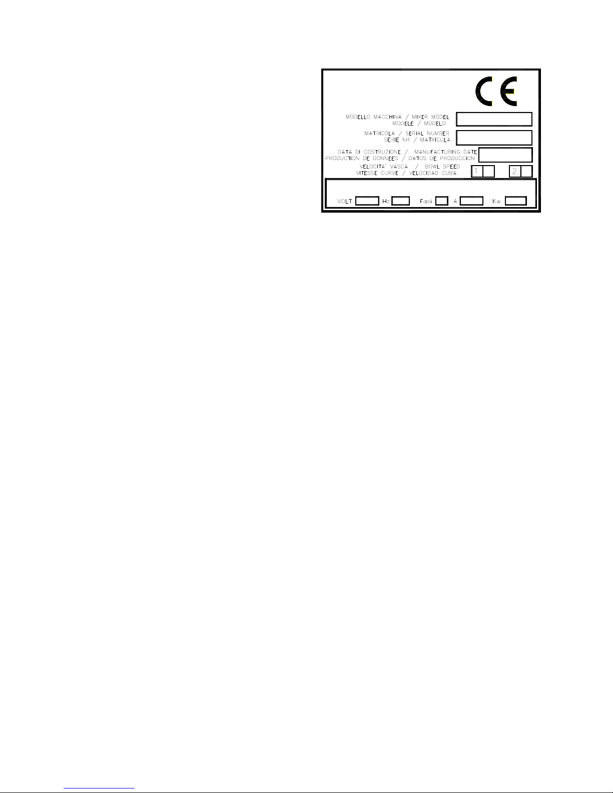
1.4 IDENTIFICATION
Each machine has an identification plate (Fig.
2) positioned at the rear (22 Fig. 1), that
provides the following information:
- Manufacturer’s name and address;
- «CE» marking;
A) Model of the machine;
B) Serial number;
C) Year of manufacture;
The data plate also indicates:
Volts : Voltage
Hz : Frequency
kW : Kilowatts
A : Amperes
The information on the machine’s identification
plate must be copied into page 2 of this
manual and must always be stated when
spare parts and/or assistance are required.
The «IRIS» dough mixer is equipped with
the following items as part of the standard
supply:
- Operation and maintenance manual of the
machine with a list of spare parts;
- Wiring diagram;
- «CE» Declaration of conformity.
CARATTERISTICHE ELETTRICHE / ELECTRICAL CHARACTERISTICS
CARACTERISTIQUES ELECTRIQUES / CARACTERISTCAS ELECTRICA
Fig. 2 - Identification plate
1.5 NOISE LEVEL
When the dough mixer is operating, the noise
level at the operator’s station is less than 70 dB.
1.6 TECHNICAL SPECIFICATIONS
- Stainless steel bowl;
- Dough tool in highly resistant stainless steel;
- Moving parts assembled on bearings;
- Safety device with lock and immediate brake
that stops the motor as soon as the protective
grille is raised;
- Stove enamelled finish;
- V-belt transmission;
- Two mixing speeds;
- 24 Volt low voltage control panel;
- Two timers.
The timers stop when the protective grille is
raised during the work cycle, in both the first and
second speed mode. The cycle will continue
when the «START» key is pressed and the timers
will start from the same point in which they
stopped.
Page 8
_______________________________
DOUGH
MIXER IRIS
_______________________________
7
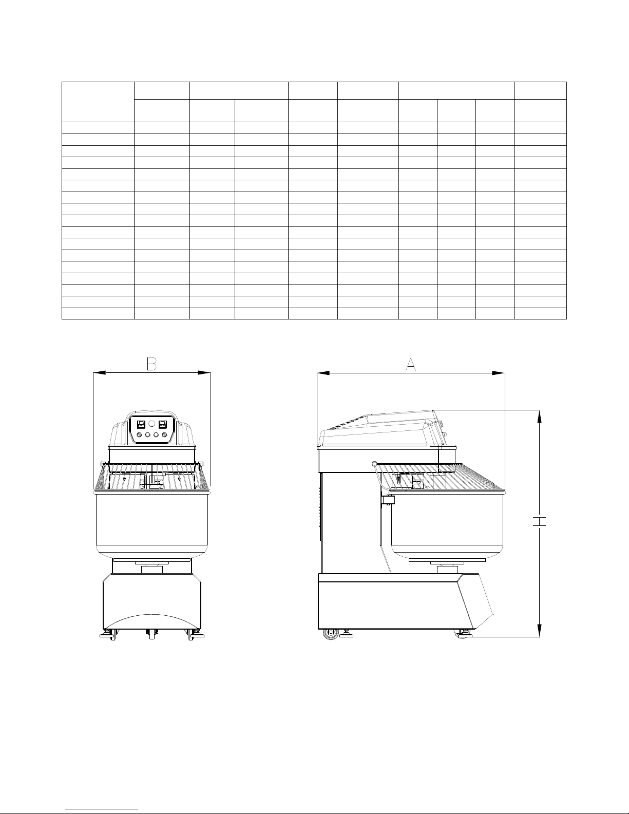
POWER DOUGH FLOUR BOWL DIMENSIONS WEIGHT
MIXER
MODEL
KW
Kg.
minimo
Kg.
massimo
Kg. Lt.
A
cm. B cm. C cm.
Kg.
IRIS 30
1,9 2 30 20 54 57 89 119 200
IRIS 40
1,9 4 40 27 63 57 89 119 200
IRIS 60
4,6 5 60 36 95 64 101 139 330
IRIS 80
4,6 6 80 50 127 75 119 145 410
IRIS 80-D
5,7 6 80 50 127 75 119 145 410
IRIS 100
5,7 8 100 65 145 75 119 145 410
IRIS 100-D
6,4 8 100 65 145 75 119 145 410
IRIS 130
6,9 12 130 80 193 85 140 150 580
IRIS 130-D
9,5 12 130 80 193 85 140 150 580
IRIS 160
8,5 15 160 100 250 95 156 160 740
IRIS 160-D
12,5 15 160 100 250 95 156 160 740
IRIS 200
8,5 17 200 125 275 95 156 160 740
IRIS 200-D
12,5 17 200 125 275 95 156 160 740
IRIS 250
9,7 22 250 150 320 105 163 160 790
IRIS 250-D
17,2 22 250 150 320 105 163 160 790
IRIS 300
12,5 27 300 180 420 113 173 166 840
IRIS 300-D
17,2 27 300 180 420 113 173 166 840
Fig. 3 - Dimensions of the machine
Page 9

_______________________________
DOUGH
MIXER IRIS
_______________________________
8
SECTION 2
General safety rules
2.1 SAFETY
WARNING
The user must train the personnel about the
risk of injuries, about the safety devices
installed in order to safeguard the operator
and about the general accident-prevention
rules established by the laws in force in the
country where the machine is installed.
Operator safety is of prime importance for
machine manufacturers. When creating a
new machine, manufacturers do all in their
power to foresee all the potentially dangerous
situations and naturally install all the
necessary protections. However, the number
of accidents caused by careless and inexpert
use of machines remains high. A distracted,
thoughtless and over-confident attitude often
leads to accidents, as can tiredness and
drowsiness.
It is therefore obligatory to read this manual
carefully, particularly the safety rules, and to
take great care when carrying out operations
that are particularly dangerous. This manual
must accompany the machine if it is moved to
another site or resold, until the time it is
completely dismantled.
The Manufacturer declines all liability for
failure to comply with the safety and
accident-prevention regulations.
WARNING
Pay attention to this symbol when it
appears in the manual. It highlights a
possible danger.
THERE ARE THREE HAZARD LEVELS:
- The word «DANGER» signals the
maximum danger level and warns that
unless the described operations are carried
out correctly, they will cause serious
injuries, death or long-term health risks.
- The word «WARNING» warns that unless
the described operations are carried out
correctly, they could cause serious
injuries, death or long-term health risks.
- The word «CAUTION» warns that unless
the described operations are carried out
correctly, they could cause damage to
the machine and/or the person.
2.1.1 TERMINOLOGY USED
• USER: The user is the person, body or
company who/that has purchased or rented
the machine and who/that intends to use it for
the purposes for which it has been designed.
• DANGER ZONE: Any zone inside and/or
near a machine where the presence of an
exposed person could put the safety and
health of that person at risk.
• EXPOSED PERSON: Any person who is
wholly or partly in a danger zone.
• OPERATOR: The person or persons
charged with installing, setting at work,
adjusting, servicing, cleaning, repairing and
transporting a machine.
• SPECIALIZED PERSONNEL: These are
those persons who have been specially
trained and authorized to carry out
maintenance work or repairs requiring
particular knowledge of the machine, the way
it works, the safety devices, the way of acting,
who are able to recognize the dangers
deriving from using the machine and are
therefore able to avoid them.
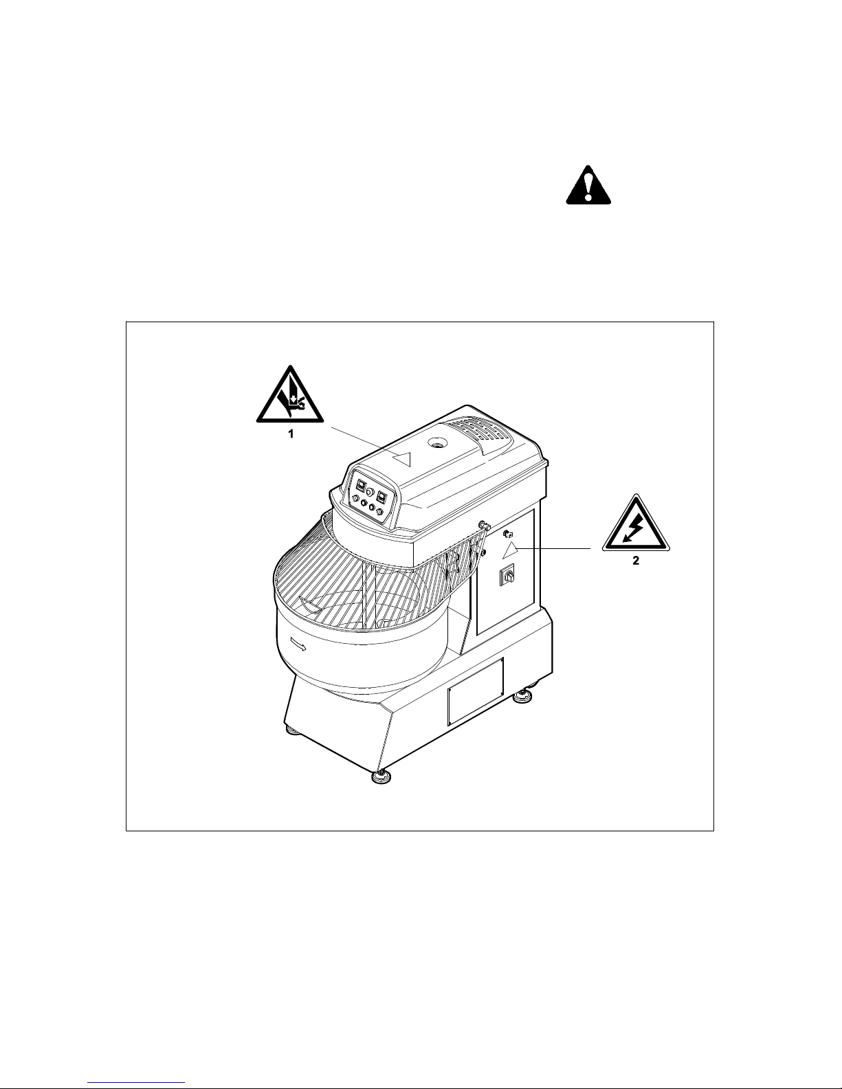
2.2 SAFETY DECALS
All possible measures were taken when the
machine was built in order to safeguard the
operators. Despite all this, there may still be
further residual risks that are indicated on the
machine my means of decals. This decals
(pictograms), illustrated in Fig. 4, are affixed
to the machine and point out the various
potentially unsafe and dangerous situations in
a schematic form.
Page 10
_______________________________
DOUGH
MIXER IRIS
_______________________________
9
Keep the decals clean and replace them
immediately if they detach or become
damaged.
With reference to Fig. 4, read the following
explanations carefully and memorize them.
1) Risk of injuries to the limbs. Take care
of the moving transmission belts when the
cover is raised.
2) Danger of high voltage. Do not work on
the electrical equipment unless the
machine has been disconnected from the
electric power source.
2.3 CLOTHING
WARNING
- Wear appropriate clothing. Do not wear
wide or loose clothing, necklaces, scarves,
ties, etc., which could become caught up in
moving parts. Long hair must be tied back.
Fig. 4 - Positions of the safety decals
Page 11
_______________________________
DOUGH
MIXER IRIS
_______________________________
10
2.4 ECOLOGY AND POLLUTION
WARNING
- Products used for cleaning purposes must be
disposed of in compliance with the laws in
force in the country where the machine is
used.
- Have packaging materials and processing
waste disposed of by specialized companies
authorized to collect and dispose of
differentiated waste.
- If the machine is dismantled, comply with the
anti-pollution laws in force in the country of
use.
2.5 SAFE USE OF THE MACHINE
DANGER
- It is absolutely forbidden to operate the
machine or have it operated by persons who
have not read and understood the instructions
in this manual, or by incompetent persons or
those who are not in good conditions of health.
- Make sure that all the safety devices are in
perfect conditions before starting up the
machine.
- Become familiar with the controls and their
functions before beginning work.
- It is absolutely forbidden to remove or tamper
with the safety devices.
- The area in which the machine is used must
be considered a «danger zone», especially for
persons who have not been trained to use the
machine.
- Before starting the machine, make sure that
there are no persons or animals in the
surrounding area.
- When a person is in a «danger zone», the
operator must act immediately, stop the
machine and possibly have the person in
question move out of the zone.
- It is absolutely forbidden to leave the machine
unattended when it is operating.
- It is absolutely forbidden to touch moving
parts or get between them.
- Before proceeding with any of the servicing
operations, disconnect the machine from the
power source and wait until all the moving parts
have come to a complete stop.
2.6 SAFE MAINTENANCE
WARNING
- Periodically check to make sure that the
overall machine and the safety devices are in
perfect conditions.
- It is obligatory to wear protective clothing,
work gloves to safeguard against cuts and
non-slip footwear with hard toe-tips when
servicing and repairing the machine.
- Spare parts must conform to the
specifications defined by the Manufacturer.
Only use genuine spares.
- Do not proceed with any servicing or cleaning
work unless the machine has been
disconnected from the electric power source.
- Strictly comply with the maintenance
instructions described in this manual. Have any
damaged or worn parts replaced by specialized
personnel.
- This instruction manual must be read,
memorized and kept throughout the entire
life of the machine.
Page 12

_______________________________
DOUGH
MIXER IRIS
_______________________________
11
SECTION 3
Transport and installation
3.1 TRANSPORT
If the machine must be transported for a long
distance, it can be easily loaded on to a truck
or other means of transport.
The dough mixer is usually supplied packed,
strapped, palletized and in a vertical position.
This means that the machine can be easily
moved, loaded or unloaded with a normal lift
truck. If the machine is moved without pallets, it
must be harnessed as illustrated in figure 5 and
lifted with a crane.
DANGER
Before proceeding with the lifting
operations, make sure that any mobile parts
of the machine are securely locked in place.
The lifting and transporting operations can
be very dangerous unless they are carried
out with the utmost care. Have anyone who
is not directly involved in the work move
well away; clear and delimit the area where
the operations will take place; make sure
that the lifting and handling means used are
in perfect conditions and fit for the job; do
not touch hanging loads and keep at a
safety distance away; the loads must not be
raised more than 20 centimeters from the
ground when they are transported. Make
sure that the work area is clear and that
there is an «escape route», i.e. a safe, free
area that can be rapidly accessed to the
operators should the load drop. To prevent
the load from shifting, the surface on to
which the machine is loaded must be
perfectly horizontal.
Once the machine has been transferred to the
means of transport, make sure that it remains
well locked in position and is unable to move.
Fix it firmly to the surface on which it has been
placed using taut ropes to prevent it from
shifting in any way.
3.2 INSTALLATION
After having made sure that the machine is in a
perfect condition, it can be positioned.
Bear the following details in mind when
choosing the definitive position for the
machine:
- choose a place that is free from damp and
sheltered from the weather conditions;
- the surface on which the machine is placed
must be perfectly flat, non-slip and with a load
capacity fit to bear the weight of the machine;
- allow for a clear, uncluttered work area around
the machine;
Fig. 5 - Lifting the dough mixer.
- the place in which the machine is positioned
must be supervised or closed, to prevent it from
being accessed by children or persons who have
not been trained to use it;
- the installation site must possess good lighting
that complies with the relative standards;
Page 13

_______________________________
DOUGH
MIXER IRIS
_______________________________
12
- the position must be near an electric panel
with a magnetothermic circuit-breaker;
- the voltage rating of the electricity main must
correspond to the value given on the
identification plate (Fig. 2);
- the electricity main must be equipped with a
grounding circuit that complies with the relative
standards;
- the ambient temperature must be between
+10° and +40°C;
- the machine must not be installed in a work
environment where there is an explosive
atmosphere.
3.2.1 POSITIONING
After the machine has been positioned and
bearing in mind the indications given in section
«3.2 Installation», proceed by ensuring that the
machine stands in a firm and stable way.
The mod. IRIS dough mixer has three wheels,
of which the front one is a castor (7 Fig. 1),
allowing it to be easily moved. After having
complied with the instructions given in the
previous section, lock the machine in the
required position and level it by means of its
adjustable feet (6 Fig. 1).
Fig. 6 – Plug
3.2.2 ELECTRICAL CONNECTION
DANGER
The machine must only be connected to the
electricity main by specialized and authorized
persons.
It is advisable to consult the wiring diagram of
the machine before proceeding.
Check the voltage rating of the electricity main in
the room and make sure that it corresponds to
the operating voltage of the machine’s electrical
system.
After having made the correct connection, start
the machine and make sure that the bowl turns in
the direction indicated by the arrow (18 Fig.1). If
this is not the case, invert two of the phases in
the plug (R and S - Fig. 6).
DANGER
If you are doubtful about the machine’s safety
systems, stop the machine and check them.
You may contact your nearest authorized
assistance service, the importer or the
Manufacturer if necessary.
3.3 GENERAL INSPECTION
WARNING
Carefully check to make sure that the machine
is efficient and that safety devices are
perfectly functional before setting the dough
mixer at work. Make sure that there are no
damaged components, that all the parts have
been installed correctly and that they function
perfectly.
Unsafe safety devices or damaged parts must
be repaired or replaced by specialized
personnel or by an Assistance center
authorized by the Manufacturer.
SECTION 4
Instructions for use
Page 14

_______________________________
DOUGH
MIXER IRIS
_______________________________
13
4.1 PRIOR TO USE
ATTENZIONE
It is advisable to remind the operator that
he is obliged to read and understand the
instructions in this manual, particularly
the ones in «Section 2» dedicated to
safety, before proceeding with normal use
of the machine. The operator must also
check to make sure that the machine is in
order and that any parts liable to wear and
deterioration are perfectly efficient.
DANGER
ALL THE ASSEMBLY, DISASSEMBLY
OPERATIONS AND ADJUSTMENTS MUST
ONLY BE CARRIED OUT AFTER THE
MACHINE HAS BEEN SWITCHED OFF
(MAIN SWITCH IN THE OFF POSITION)
AND AFTER IT HAS BEEN
DISCONNECTED FROM THE
ELECTRICITY MAIN.
4.1.1 CONTROL PANEL
(version 80-250)
The entire operating cycle of the dough mixer
is controlled by means of the control panel,
the voltage of which is reduced to 24 Volts
(Fig.7).
1) «First speed» timer. Used to select the
required time setting (in minutes).
2) Emergency button. Press this button to
disconnect the power source and stop all
the functions of the machine. The cycle
can be reset by turning the button and
then pressing the START button.
3) «Second speed» timer. Used to select
the time required (in minutes) to complete
the work cycle and obtain a homogeneous
dough that corresponds to the
specifications required by the operator.
4) Bowl rotation reversal selector.
Selector with two positions, plus neutral.
Reverses the rotation direction at the slow
speed only.
5) START button with indicator light.
Press this button to begin the work cycle.
When on, the indicator light shows that
the machine is powered.
6) Bowl rotation button. This button stops
the dough tool from turning and can
operate in both the continuous and
intermittent mode. By keeping the button
depressed, the bowl will turn. If it is
pressed intermittently, the bowl will turn to
a sufficient extent to allow the operator to
empty it.
7) Second speed cut-out switch. Allows
dough to be made using the slow speed
only. Turn the switch towards the right to
inhibit the second speed.
4.1.2 CONTROL PANEL
(version 30-40)
Consult the instructions in the previous
paragraph (4.1.1) in relation to points 1), 2)
and 3).
Points 4), 5), 6) and 7) are not pertinent to
this model of the machine.
8) Start button to start the machine.
4.2 USE
WARNING
The operator must supervise the area in
which the dough mixer is installed so as
to prevent unauthorized persons from
accessing the so-called danger zones
whilst the machine is working. He must
also keep the area constantly clean and
free from obstacles.
Page 15

_______________________________
DOUGH
MIXER IRIS
_______________________________
14
Fig. 7 - Control panel
4.2.1 HOW TO START THE DOUGH
MIXER
DANGER
IT IS ABSOLUTELY FORBIDDEN TO
USE THE MACHINE WITHOUT ITS
GRILLE AND PROTECTIVE CASING.
After having made all the adjustments, start
the machine and begin work.
1) Place the required quantities of flour,
water and any other ingredient required,
into the bowl.
2) Plug the machine into the electricity main,
then turn the main switch (Fig. 8) to the
ON position.
3) Now select the mixing times (if these have
not yet been memorized) by means of the
two timers (1 and 3 Fig. 7).
4) Press the START button - (5 Fig. 7) in
models 80-250, or (8 Fig. 7) in models 3040 - in order to start the operating cycle. If
the operator has selected the dough
mixing time settings in timer (1 Fig. 7) and
timer (3 Fig. 7), the machine will terminate
the work cycle during which it will
automatically switch from the first to the
second speed.
After the automatic stop, the mains voltage
is not disconnected and the machine is
ready for another batch of dough.
4.2.2 HOW TO TAKE PRODUCT FROM
THE BOWL
Proceed in the following way to take product
from the bowl:
1) Turn the selector (4 Fig. 7) in the opposite
direction to that of operation and then press
the START button.
The dough tool will turn in the opposite
direction, thus bringing most of the dough
towards the center of the bowl.
Page 16

_______________________________
DOUGH
MIXER IRIS
_______________________________
15
Fig. 8 - Machine’s main switch with two
positions (Fig.8), ON - OFF. The door that
accesses the electric panel remains locked in
the ON position
2) Lift the protective grille (4 Fig. 1) to
immediately stop the motors.
3) Now start to remove the dough.
The button (6 Fig. 7) allows the operator to
turn the bowl continuously or intermittently
and to access the part with the dough in
an easier way.
After this and if there are no other operations
to carry out, stop the machine in the
following way:
- press the red stop button (2 Fig. 7);
- turn the switch on the machine (Fig. 8) to
the OFF position;
- disconnect the machine from the electric
power source by means of the main switch
on the electricity main, prior to the
machine itself.
4.3 EMERGENCY STOP
Whenever the operator decides that the
machine must be blocked and prevented from
operating, he can raise the protective grille or
press the EMERGENCY button (red) on the
control panel. This latter action deactivates
the electric power supply.
4.4 CLEANING AFTER USE
WARNING
Disconnect the machine from the electric
power source before beginning to clean
the machine.
Remove any wet or dry residues and flour
dust with a slightly damp cloth.
WARNING
Never use continuous jets of water and
avoid splashing water indirectly in order
to clean the floor around and under the
machine. Once a month, remove the cover
and clean off the dust and residues from
the transmission with a vacuum cleaner.
Once the dough making and cleaning
operations have terminated, always make
sure that the electric power source has
been disconnected.
Page 17

_______________________________
DOUGH
MIXER IRIS
_______________________________
16
SECTION 5
Maintenance
5.1 ROUTINE MAINTENANCE
This range of dough mixers with fixed bowls
does not require any particular maintenance
work. However, tip-top performance and a
perfectly efficient machine are only obtained by
methodic and regular compliance with the
following regulations.
WARNING
The servicing, adjusting and preparation
jobs must always be carried out when
the machine is off and disconnected
from the electric power source.
- Maintenance work and adjustments may
only be carried out after the electric
power source has been disconnected by
turning off both the mains circuit-breaker
and the machine’s main switch (Fig. 8).
The routine maintenance operations can
be carried out by the operator, while
more complex jobs must be done by
specialized and authorized personnel.
- The general condition of the machine
must be inspected and the machine itself
cleaned daily, or as frequently as
possible.
- Excessively worn or broken parts must
be replaced immediately.
- The wiring diagram, which is supplied
together with the machine, must be kept
with care and consulted whenever
necessary. As soon as the machine is
received, it is advisable to make a copy
of the diagram and keep it with the other
documents.
5.2 BELT TRANSMISSION
The belts normally wear in an almost uniform
way, even though this wear may take place at
different times in one transmission as regards
the other and is bound to the consistency of the
dough as well as the number of hours that the
machine is used each day.
Every so often, the operator must therefore
check the degree of wear on all the belts in the
machine. Remember that if replacements are
required, the Manufacturer recommends
replacing all the belts at the same time
(complete replacement of each set of belts).
Fig. 9 - Dough tool belt tensioning
1) Belt stretcher fixing screws (4). - 2) Motor belt tension adjuster screw. - 3) Motor fixing screws (4).
- 4) Dough tool belt tension adjuster screw.
Page 18

_______________________________
DOUGH
MIXER IRIS
_______________________________
17
5.2.1 DOUGH TOOL TRANSMISSION
If the dough tool seems slow to turn, the
transmission belts may have loosened or be
broken. Proceed in the following way to
adjust and/or replace the belts:
1) Using a pipe wrench, unscrew the central
nut that fixes the cover to the machine (2 Fig. 1).
Raise the cover, paying particular
attention to the electric cables of the control
panel, which cannot be detached.
2) Loosen the four screws (1 Fig. 9) at the
base of the belt stretcher. Use the screw of
the belt stretcher (4 Fig. 9) to adjust the
tension of the transmission pulley/dough tool
belts.
Fig. 10 - Electric panel of IRIS 80-250
1) Thermic relay reset button. - 2)
Magnetothermic switches and fuses
Fig. 11 - Components of the electrical system
of IRIS 30-40
1) Thermic relay reset button. - 2)
Magnetothermic switches and fuses
3) Retighten the four screws (1 Fig. 9).
4) Loosen the four screws (3 Fig. 9) on
the motor bearing plate. Use the screw of the
belt stretcher (4 Fig. 9) to adjust the tension
of the motor pulley/transmission belts.
5) Retighten the four screws (3 Fig. 9).
6) Fit the upper cover back in place and
fix it with the relative nut (2 Fig. 1).
To replace any broken belts, remove the
cover and loosen the four screws that fix the
belt stretcher, as described previously, then
replace the broken belts. Always refer to the
spare parts tables which show the location of
the various different components. At the end
of the operation, tighten the belts in the
correct way and fit the upper cover back in
place.
5.2.2 BOWL TRANSMISSION
If the bowl seems slow to turn, the
transmission belts may have loosened or
be broken. Proceed in the following way to
adjust and/or replace the belts:
1) Turn the belt tightening knobs (24 Fig. 1)
positioned at the base of the machine (2
knobs in models 80-250, 1 knob in models
30-40).
Page 19

_______________________________
DOUGH
MIXER IRIS
_______________________________
18
Screw clockwise to tighten the belts,
unscrew to loosen or completely annul the
belt tension.
To replace any broken belts, first loosen them
with the two knobs (24 Fig. 1), remove the
side inspection panel (8 Fig. 1), then
replace the broken belts. Always refer to
the spare parts tables which show the
location of the various different
components. At the end of the operation,
tighten the belts in the correct way and fit
the side inspection panel back in place
with the relative four screws.
5.3 STORAGE
If the machine is to remain idle for a long
period of time, it must first be thoroughly
cleaned, the parts liable to wear must be
lubricated and the entire machine covered
with a plastic cloth.
If these operations are carried out with care, it
will be all to the advantage of the user, who
will find the machine in an excellent condition
when it is required for use once more.
Comply with the laws in force in the country
where the machine is used when it comes to
the way the products used for cleaning and
servicing the machine are used and disposed
of. Also comply with the recommendations of
the manufacturers of such products.
WARNING
If the machine is dismantled, comply with
the anti-pollution laws in force in the
country of use.
Page 20

_______________________________
DOUGH
MIXER IRIS
_______________________________
19
5.4 TROUBLESHOOTING
The following tables list the main faults, along with the relative causes and suggested remedies, to
which the machine may be subjected as it operates (NOTE: some of the indications are not
applicable to models 30-40).
Any operations required must be carried out by expert and authorized technicians and only after
having examined this manual.
FAULTS PROBABLE CAUSES POSSIBLE REMEDIES
The machine stops during
the work cycle but the green
starter indicator light
remains on.
The bowl is too full or the
voltage supply from the
electricity main is irregular.
Open the electric panel door (21
Fig. 1) and make sure that the
thermic relays and fuses function
correctly. If necessary, re-activate
the thermic relay by pressing the
button (1 Fig. 10). If the machine still
fails to operate, contact the Retail
Outlet’s Assistance Service.
The dough tool slows down
while the dough is being
mixed.
The dough tool’s transmission
belts have slackened or are
broken.
Tighten or replace the belts as
described in paragraph «5.1.1
Transmission belts».
The bowl slows down while
the dough is being mixed.
The bowl’s transmission belts
have slackened or are broken.
Tighten or replace the belts as
described in paragraph «5.1.1
Transmission belts».
When the START button is
pressed (5 Fig. 7 ), the
machine starts operating
but stops as soon as the
button is released.
The timer (1 Fig. 7) or the
relays of the electric panel
(Fig. 10) are dirtied with flour
or out of service.
Direct a jet of air (not too strong) on
to the timer and relays so as to
clean the contacts. If the machine
still fails to start, replace the
defective component.
When the START button is
pressed (5 Fig. 7), the
dough tool turns while the
bowl remains at a standstill.
Make sure that the bowl’s
mode selector (4 Fig. 7)
functions correctly. It could be
out of service.
Replace the selector if it is
defective.
The machine fails to
automatically switch from
the first to the second
speed.
The speed selector (7 Fig. 7)
is in the second speed
inhibited position.
The selector is defective.
Not enough power from the
electricity main.
Check the position of the second
speed inhibiting selector (7 Fig.7).
Replace the selector.
Check the power installed in the
bakery. Boost the power if
necessary.
Page 21

_______________________________
DOUGH
MIXER IRIS
_______________________________
20
FAULTS PROBABLE CAUSES POSSIBLE REMEDIES
The machine fails to
automatically switch from
the first to the second
speed.
The mains voltage is different
from that of the machine.
The second speed timer (3
Fig.7) is in the neutral position.
Check the mains voltage.
Make sure that the timer is in the
correct position (3 Fig. 7).
The machine is very noisy
and the protecting thermic
relays often stop it from
operating.
The machine may be powered
by two phases instead of
three.
Check the positions of the
magnetothermic switches (Fig. 10)
and the power cable connections.
When the main switch is
turned on (20 Fig. 1), the
indicator light (5 Fig. 1) fails
to come on and the
machine is not powered.
The wires in the mains plug
have detached.
The mains circuit-breaker is
broken.
Check the mains connections.
Replace the main circuit-breaker.
The machine fails to
operate when the START
button is pressed.
The button is broken.
The timers (1 and 3 Fig. 7) are
in the zero position.
The protective grille (4 Fig. 1)
is open.
The protective grille limit
switch is not positioned
correctly or is defective.
The protective
magnetothernmic switches
(Fig. 10) have tripped or are
faulty.
The stop button (2 Fig. 7) is in
the blocked position or is
defective.
Replace the START button.
Enter the operating values in the
timers.
Close the protective grille.
Check the grille limit switches.
Consult the relative spare parts
table for its position.
Position the magnetothermic
switches correctly or replace them if
necessary. Replace the protective
fuses.
Release the emergency button or
replace the contacts.
Page 22

_______________________________
DOUGH
MIXER IRIS
_______________________________
21
SECTION 6
Spare parts
6.1 HOW TO ORDER SPARE PARTS
The various components of the machine can
be ordered from:
-------------------------------------------------
-------------------------------------------------
-------------------------------------------------
-------------------------------------------------
-------------------------------------------------
-------------------------------------------------
-------------------------------------------------
specifying:
• The model of the machine.
• The serial number of the machine.
• Year of manufacture.
• Order number of the part.
• Description of the part and quantity required.
• Means of transport. If this item is not specified
and although particular care is taken with this
service, the Manufacturer shall not be liable for
any delays in shipment due to unforeseen
circumstances. The shipment expenses are
always at the consignee’s charge. The goods
travel at the principal’s risk and peril even if sold
ex destination.
Lastly, remember that the Manufacturer is
always at your disposal for any assistance
and/or spare parts required.
6.2 SPARE PARTS TABLES
Tab. 1 Dough mixer IRIS 30-40
Tab. 2 Dough mixer IRIS 80-250
– Structure and panels
Tab. 3 Dough mixer IRIS 80-250
- Upper drive unit
Tab. 4 Dough mixer IRIS 80-250
- Bowl and protections
Tab. 5 Dough mixer IRIS 80-250
- Lower drive unit
Page 23

_______________________________
DOUGH
MIXER IRIS
_______________________________
22
TAV. 01 Dough mixer IRIS 30-40 rev.00
Page 24

_______________________________
DOUGH
MIXER IRIS
_______________________________
23
TAV. 01 Dough mixer IRIS 30-40 rev.00
Pos. Mod. 30 Mod. 40 Descrizione
1 306200270 306200270 * PLASTIC LID IRIS 30-40
2 463200007 463200007 ELECTRONIC TIMER 1ST SPEED 48x48
3 464102002 464102002 COMPLETE GREEN START BUTTON - MIXER IRIS
4 464102005 464102005 COMPLETE RED EMERGENCY BUTTON - MIXER IRIS
5 463200007 463200007 ELECTRONIC TIMER 2ST SPEED 48x48
6 553110010 553110010 CONTROL PANEL MIXER 30-40 IRIS
7 554110041 554110041 ELECTRIC PANEL MIXER 30-40/IRIS IN 220/50
7 554110043 554110043 ELECTRIC PANEL MIXER 30-40/IRIS IN 400/50
7 554110042 554110042 ELECTRIC PANEL MIXER 30-40/IRIS IN 220/60
7 554110044 554110044 ELECTRIC PANEL MIXER 30-40/IRIS IN 400/60
8 423240041 423240041 TRAPEZOIDAL BELT
9 321400370 321400370 PIRAL PULLEY
10 321400510 321400510 MIXER SPIRAL MOTIVE PULLEY
11 462660002 462660002 ON-OFF MAIN ROTATING SWITCH
12 429202207 429202207 MOBILE FLANGE SUPPORT d.35
13 421025001 421025001 OBLIQUE BEARING
14 420812010 420812010 RADIAL BEARING
15 422600003 422600003 OIL BLOCK
16 369000010 369000010 * SMALL PLASTIC CUP
17 315000290 315000290 SPIRAL MIXER TRANSMISSION SHAFT
18 429202207 429202207 MOBILE FLANGE SUPPORT d.35
19 308600290 308600290 * BACK AIRING PANEL
20 490202015 490202015 DRAWN ROD D. 15
21 301100260 301100260 * MIXER BODY IRIS 30-40
22 352600030 352600030 MIXTURE BLOCK FIXING BRACKET
23 356000180 356000180 WHITE PROFILE IN Pe500 DESIGNED FOR PA
24 362400516 362400515 MIXTURE BLOCK PROTECTION
25 315000040 315000040 MIXER SPIRAL HOLDER SHAFT
26 372700040 372700040 MIXER SPIRAL
27 362500130 362500120 METAL BOWL PROTECTION
28 331700060 331700040 MIXER COLUMN
29 420812010 420812010 RADIAL BEARING
30 361900012 361900022 BOWL WITH BURR
31 315100030 315100030 BOWL-HOLDER SHAFT - MIXER 40
32 483010005 483010005 PLASTIC FOOT ARTICULATED STEM Fe
33 429321002 429321002 TWINNED RUBBER WHEEL GIR. SUPPORT
34 421025001 421025001 OBLIQUE BEARING
35 423210038 423210038 TRAPEZOIDAL BELT
36 321400390 321400390 BOWL PULLEY
37 315400050 315400050 TRANSMISSION CLUTCH PIN
38 321400450 321400450 BOWL TRANSMISSION MOTIVE PULLEY
39 345500010 345500010 WELDED NUT ANTI-ROTATION MIXER BELT REG.
40 420812001 420812001 TRANSMISSION BEARING
41 303900310 303900310 BOWL TRANSMISSION SUPPORT
42 415010122 415010122 BOWL TRANSMISSION SHAFT KEY
43 315000280 315000280 BOWL TRANSMISSION SHAFT
44 415010151 415010151 BOWL SUPPORT SHAFT KEY
Page 25

_______________________________
DOUGH
MIXER IRIS
_______________________________
24
TAV. 01 Dough mixer IRIS 30-40 rev.00
45 410192010 410192010 THREADED BAR
46 482550003 482550003 WHEEL 6 LOBE PASSING HOLE
47 423240032 423240032 TRAPEZOIDAL BELT
48 321400380 321400380 BOWL TRANSMISSION DRIVEN PULLEY
49 321400400 321400400 SPIRAL TRANSMISSION DRIVEN PULLEY
50 423240017 423240017 TRAPEZOIDAL BELT
51 321400490 321400490 MIXER MOTOR PULLEY
52 467341200 467341200 MOTOR 2°V IRIS 30-40 IN 220/50
52 467341400 467341400 MOTOR 2°V IRIS 30-40 IN 400/50
52 467341300 467341300 MOTOR 2°V IRIS 30-40 IN 220/60
52 467341500 467341500 MOTOR 2°V IRIS 30-40 IN 400/60
53 321400500 321400500 BOWL TRANSMISSION MOTIVE PULLEY
54 315400070 315400070 PIN MOTOR SUPPORT CLUTCH
55 303900071 303900071 BOWL MOTOR MOBILE SUPPORT
56 410192010 410192010 THREADED BAR
COLOURS
* WHEN ORDERING PLEASE SPECIFY MIXER COLOUR
WHEN ORDERING PARTS PLEASE SPECIFY REGISTRATION NUMBER
CODE COLOUR
BASE CODE -01 WHITE
BASE CODE -02 CREAM
BASE CODE -03 METAL GREY
BASE CODE -04 LIGHT BLUE
BASE CODE -05 YELLOW
Page 26

_______________________________
DOUGH
MIXER IRIS
_______________________________
25
Page 27

_______________________________
DOUGH
MIXER IRIS
_______________________________
26
TAV. 02 Dough mixer IRIS 60-300 - Structure and panels Rev.001
01-06-2012
Page 28

_______________________________ DOUGH MIXER IRIS _______________________________
27
TAV. 02 Dough mixer IRIS 60-300 - Structure and panels Rev.001 01-06-2012
Pos. Mod. 60 Mod. 80 Mod. 100 130 Mod. Mod. 16 Mod. 200 Mod. 250 Mod. 300
Descrizione
1*
306200520 306200120 306200120 306200210 306200140 306200140 306200140 306200140
* PLASTIC MIXER LID
2
410347010 410347010 410347010 410347010 410347010 410347010 410347010 410347010
BLIND INOX NUT
3
411015010 411015010 411015010 411015010 411015010 411015010 411015010 411015010
PLANE INOX WASHER
4
362600020 362600020 362600020 362600020 362600020 362600020 362600020 362600020
MIXER CONTROL PANEL COVER
5
463200007 463200007 463200007 463200007 463200007 463200007 463200007 463200007
ELETRIC TIMER 1ST SPEED 48x48
6*
464102001 464102001 464102001 464102001 464102001 464102001 464102001 463402001
COMP. SWITCH SIEMENS INV. BOWL MIXER IRIS
7*
464102002 464102002 464102002 464102002 464102002 464102002 464102002 463402002
* COMPLETE GREEN BUTTON SIEMENS STA RT MIXER IRIS
8*
464102003 464102003 464102003 464102003 464102003 464102003 464102003 463402003
* COMPLETE BLACK BU
TTON TELEMECANIQUE BOWL ROTAT ION
9*
464102004 464102004 464102004 464102004 464102004 464102004 464102004 463402004
* COMPL. BLACK SWITCH SIEMENS LOW /HIGH SPEED IRIS
10
463200007 463200007 463200007 463200007 463200007 463200007 463200007 463200007
ELETRIC TIMER 2ST SPEED 48x48
11*
460201002 460201002 460201002 460201002 460201002 460201002 460201002 460201002
* SCREEN-PRINTED PANEL FOR MIXER IRIS
12*
464102005 464102005 464102005 464102005 464102005 464102005 464102005 463402005
* COMPLETE RED BUTTON SIEMENS EMERG. IRIS
13*
553120020 553120020 553120020 553120020 553120020 553120020 553120020 553120020
* CONTROL PANEL MIXER 60-300 IRIS DIGITAL E LETTROMEC. SIEMENS
13*
553120010 553120010 553120010 553120010 553120010 553120010 553120010 553120010
* CONTROL PANEL MIXER 60-
300 IRIS ELETTROMEC. TELEMECANIQUE
14
356300040 356300040 356300040 356300040 356300040 356300040 356300040 356300040
THREADED BAR
15
410320010 410320010 410320010 410320010 410320010 410320010 410320010 410320010
HEXAGONAL NUT
16*
308600290 308600290 308600290 308600290 308600290 308600290 308600290 308600290
* BACK MIXER AIRING PANEL
17
482520002 482520002 482520002 482520002 482520002 482520002 482520002 482520002
LOCK WITH KEY WITH FINS
18
462660007 462660007 462660007 462660007 462660007 462660007 462660007 462660007
ON-OFF MAIN ROTATING SWITCH
19*
307600011 307600010 307600010 307600040 307600020 307600020 307600020 307600020
* MIXER CONTROL PANEL DOOR
20
483010001 483010001 483010001 483010001 483010001 483010001 483010001 483010001
PLASTIC FOOT ARTICULATED STEM Fe
21
429320002 429320002 429320002 429320002 429320002 429320002 429320002 429320002
WHEEL WITH TURNING SUPPORT HEAVY CAST IRON + POLES
22
429330001 429330001 429330001 429330001 429330001 429330001 429330001 429330001
WHEEL WITH FIXED SUPPORT D100 SUPP ORT PE
23*
301100270 301100070 301100070 301100190 301100100 301100100 301100100 301100510
* MIXER BODY IRIS
24*
308600280 308600280 308600280 308600280 308600280 308600280 308600280 308600280
* LOWER INSPECTION HATCH. IRIS
* WHEN ORDERING PLEASE SPECIFY MIXER COLOUR WHEN ORDERING PARTS PLEASE SPECIFY REGISTRATION NUMBER
CODE COLOUR CODE COLOUR
BASE CODE -01 WHITE BASE CODE -04 BASE CODE -04
BASE CODE -02 PANNA BASE CODE -05 YELLOW
BASE CODE -03 METAL GREY
Page 29

_______________________________
DOUGH
MIXER IRIS
_______________________________
28
TAV. 03 Dough mixer IRIS 60-300 - Upper drive unit Rev.001
01-06-2012
Page 30

_______________________________ DOUGH MIXER IRIS _______________________________
29
TAV. 03 Dough mixer IRIS 60-300 - Upper drive unit Rev.001 01-06-2012
Pos.
Mod. 60 Mod. 80 Mod. 100 130 Mod. Mod. 160 Mod. 200 Mod. 250 Mod. 300 Descrizione
1
429005002 429005002 429005002 429000001 429000001 429000001 429000001 429000001 CONE BUSH / KEYER
2
423240074 423240085 423240085 423240093 423240096 423240096 423240096 423240096 TRAPEZODAL BELT
3
423010525* 423010525* 423010525* 321400424* 321400424* 321400424* 321400424* 321400424 *
SPIRAL DRIVEN PULLEY MIXER IRIS
4
420812008 420812011 420812011 421005007 421005007 421005007 421005007 421005007 UPPER BEARING MIXER SPIRAL IRIS
5
303800310 303800220 303800220 303800220 303800220 303800220 303800220 303800220 SPIRAL BEARING SUPPORT
6
421025003 421005004 421005004 421005007 421005007 421005007 421005007 421005007 BEARING
7
422600005 422600007 422600007 422600010 422600010 422600010 422600010 422600010 OIL BLOCK
8
315000300 315000140 315000140 315000120 315000120 315000120 315000120 315000120 MIXER SPIRAL HOLDER SHAFT
9
369000020 369000020 369000020 369000030 369000030 369000030 369000030 369000030
PLASTIC CUP
10
372700080 372700010 372700010 372700060 372700020 372700020 372700030 372700090
MIXER SPIRAL- IRIS
11
467253400 * 467263401 * 467263400 * 467263402 * 467273400 * 467273400 * 467273401 * 467273402
* SPIRAL MOTOR
12
317500050-53 317500010-53 317500010-53 317500010-53 317500020-53 317500020-53 317500020-53 317500020-53
SPIRAL MOTOR SLIDE
13
321400261 321400260 321400260 321400171 321400170 321400170 321400170 321400170
SPIRAL MOTIVE PULLEY
14
346600020 346600020 346600020 346600020 346600020 346600020 346600020 346600020
PLAIN WASHER
15
- - - - - - - - - - - - - - - - - - - - - - - - - - - - - - - - - - - - - - - -
- - - - -
16
303900131-53 303900131-53 303900131-53 303900261 303900261 303900261 303900261 303900261
SPIRAL TRANSMISSION SUPPORT MIXER
17
315000160 315000160 315000160 315000250 315000250 315000250 315000250 315000250
ALBERO PULEGGIA RINVIO
18
420812009 420812009 420812009 420812020 420812020 420812020 420812020 420812020
BEARING
19
423240014 * 423240021 * 423240021 * 423240021 * 423240031 * 423240031 * 423240031 * 423240031
* TRAPEZODAL BELT
20
321400250 * 321400250 * 321400250 * 321400430 * 321400430 * 321400430 * 321400430 * 321400430
*PULEGGIA DOPPIA
21
420812009 420812009 420812009 420812020 420812020 420812020 420812020 420812020
BEARING
22
351400080 351400080 351400080 351400080 351400080 351400080 351400080 351400080
DISTANZIALE
23
Vedi pos. 16 Vedi pos. 16 Vedi pos. 16 Vedi pos. 16 Vedi pos. 16 Vedi pos. 16 Vedi pos. 16 Vedi pos. 16
SUPPORTO RINVIO SPIRALE
* WHEN ORDERING PLEASE SPECIFY MIXER COLOUR
WHEN ORDERING PARTS PLEASE SPECIFY REGISTRATION NUMBER
Page 31

_______________________________
DOUGH
MIXER IRIS
_______________________________
30
TAV. 04 Dough mixer IRIS 60-300 - Bowl and protections Rev.001
01-06-2012
Page 32

_______________________________ DOUGH MIXER IRIS _______________________________
31
TAV. 04 Dough mixer IRIS 60-300 - Bowl and protections Rev.001 01-06-2012
Pos.
Mod. 60 Mod. 80 Mod. 100 130 Mod. Mod. 160 Mod. 200 Mod. 250 Mod. 300 Descrizione
1
362500380 362500100 362500110 362500070 362500050 362500060 362500210 362500320
METAL BOWL PROTECTION IRIS
1
362400810 362400090 362400090 362400180 362400110 362400110 362400960 362400950
* PLASTIC PROTECTION IRIS
2
464805001 464805001 464805001 464805001 464805001 464805001 464805001 464805001
BOWL PROTECTION LIMIT SWITCH
3
332800010 332800010 332800010 332800010 332800010 332800010 332800010 332800010
GRID LIMIT SWITCH STARTER RANGE
4 *
490202015 490202015 490202015 490202015 490202015 490202015 490202015 490202015
DRAWN ROD D. 15
5
334000051 334000051 334000051 334000051 334000051 334000051 334000051 334000051
GRID STOP IRIS L=35
6
334000050 334000050 334000050 334000050 334000050 334000050 334000050 334000050
GRID STOP IRIS L=70
7
511600040 511600040 511600040 511600040 511600041 511600041 511600041 511600041
ROLLER GROUP WULKOLAN WITH BEARINGS
8
315400090 315400090 315400090 315400090 315400100 315400100 315400100 315400100 THREAD PINS FOR THRUST BEARING ROLLER
9
303800400_50 303800260_50 303800260_50 303800260_50 303800360_50 303800360_50 303800360_50 303800360_50
THRUST BEARING ROLLER SUPPORT
10
352600030 352600030 352600030 352600030 352600030 352600030 352600030 352600030 MIXTURE BLOCK FIXING BRACKET
11 *
331700090 331700010 331700010 331700050 331700030 331700030 M253-93 331700070 MIXER COLUMN
12
361900031 361900041 361900051 361900061 361900071 361900081 361900091 361900100 MIXER BURR BOWL
13 *
356000180 356000180 356000180 356000180 356000180 356000180 356000180 356000180 WHITE PROFILE FOR MIXTURE STOP
14
362400511 362400510 362400511 362400512 362400513 362400514 362400517 362400760 MIXTURE BLOCK PROTECTION IRIS
15
511100190 511100050 511100050 511100050 511100060 511100060 511100060 511100060
BOWL THRUST BEARING SUPPORT GROUP
* WHEN ORDERING PLEASE SPECIFY MIXER COLOUR
WHEN ORDERING PARTS PLEASE SPECIFY REGISTRATION NUMBER
Page 33

_______________________________
DOUGH
MIXER IRIS
_______________________________
32
TAV. 05 Dough mixer IRIS 60-300 - Lower drive unit Rev.001
01-06-2012
Page 34

_______________________________ DOUGH MIXER IRIS _______________________________
33
TAV. 05 Dough mixer IRIS 60-300 - Lower drive unit Rev.001 01-06-2012
Pos.
Mod. 60 Mod. 80 Mod. 100 130 Mod. Mod. 160 Mod. 200 Mod. 250 Mod. 300 Descrizione
1
315100050 315100020 315100020 315100010 315100010 315100010 315100010 315100010 MIXER BOWL-HOLDER SHAFT
2
422600005 422600007 422600007 422600010 422600010 422600010 422600010 422600010 OIL BLOCK
3
421025003 421005004 421005004 420812012 420812012 420812012 420812012 420812012
UPPER BEARING MIXER SPIRAL IRIS
4 *
303800310 303800220 303800220 303800160 303900040 303900040 303900220 303800160 SPIRAL BEARING SUPPORT
5
420812008 420812011 420812011 421005007 421005007 421005007 421005007 421005007 LOWER SPIRAL BEARING
6
321400051 321400051 321400051 321400020 321400020 321400020 321400020 321400020 PULLEY
7
423240066 423240074 423240074 423240089 423240090 423240090 423240092 423240093 TRAPEZOIDAL BELT
8
346600030
410112091
346600030
410112091
346600030
410112091
429000004 429000004 429000004 429000004 429000004 TONGUE/KEYER
9
315400050 315400050 315400050 315400050 315400050 315400050 315400050 315400050
TRANSMISSION CLUTCH PIN
10
420812007 420812007 420812007 420812007 420812007 420812007 420812007 420812007
RADIAL BEARING
11
315000070 315000070 315000070 315000070 315000070 315000070 315000070 315000070
ALBERO PER RINVIO VASCA
12
303800250 303800250 303800250 303800250 303800250 303800250 303800250 303800250
SUPPORTO RINVIO VASCA
13
321400090 321400090 321400090 321400210 321400210 321400210 321400210 321400210
PULLEY
14
POS.22 o POS. 27 POS.22 o POS . 27 POS.22 o POS. 27 POS.22 o POS. 27 POS.22 o POS . 27 POS.22 o POS. 27 POS.22 o POS. 27 POS.22 o POS . 27
15
415010142 415010142 415010142 415010142 415010142 415010142 415010142 415010142
TONGUE
16
423240085 423240088 423240088
423240091 *
423240091 423240091 423240091 423240091
TRAPEZOIDAL BELT
17
415010175 415010175 415010175 415010175 415010175 415010175 415010175 415010175
TONGUE
18
410112132 + 410123048 + 411061006 + 346600020 + 410156038 + 411080016
TWO HOLE WASHER FOR SHAFT
19 *
467221400 467221400 467221400 467231400 467241400 467241400 467241400 467241400
SPIRAL MOTOR
20
414501040 414501040 414501040 414501040 414501040 414501040 414501040 414501040
EXTERNAL STOP RING
21
321400060 321400060 321400060 321400520 321400200 321400200 321400200 321400200
PULLEY
22
309100020-53 309100020-53 309100020-53 309100020-53 309100020-53 309100020-53 309100020-53 309100020-53
THREADED BAR
23
411008010 411008010 411008010 411008010 411008010 411008010 411008010 411008010
PLAIN WASHER
24
482550003 482550003 482550003 482550003 482550003 482550003 482550003 482550003
6 LOBE WHEEL PASSING HOLE
25
346600030 346600030 346600030 346600030 346600030 346600030 346600030 346600030
TWO HOLE WASHER FOR SHAFT
26
321400110 321400110 321400110 321400150 321400150 321400150 321400150 321400150
PULLEY
27
309100030-53 309100030-53 309100030-53 309100030-53 309100030-53 309100030-53 309100030-53 309100030-53
THREADED BAR
28
303900070-53 303900070-53 303900070-53 303900070-53 303900070-53 303900070-53 303900070-53 303900070-53
BOWL MOTOR MOBILE SUPPORT
29
315400070 315400070 315400070 315400070 315400070 315400070 315400070 315400070
PIN MOTOR SUPPORT CLUTCH
30
482550003 482550003 482550003 482550003 482550003 482550003 482550003 482550003
6 LOBE WHEEL PASSING HOLE
* WHEN ORDERING PLEASE SPECIFY MIXER COLOUR
WHEN ORDERING PARTS PLEASE SPECIFY REGISTRATION NUMBER
Page 35

_______________________________
DOUGH
MIXER IRIS
_______________________________
34
 Loading...