

Page 1

Mod: ICE32A
Production code: CB316A
11/2007
Page 2

It is strictly forb
idden to reproduce this instruction manual or any part thereof.
AUTOMATIC ICE-CUBE MAKER
INSTRUCTIONS AND WARNINGS
24478 ed. 11-2007
Page 3
Page 4
Page 5
Page 6
Page 7

Dear Customer, Congratulations on having chosen a quality product which will certainly fully
meet your expectations. Thank you for having purchased one of our products. Please read
this instructi on manual carefully before using your new automatic ice-cube maker.
TABLE OF CONTENTS
1 IMPORTANT ADVI
CE AND RECOMMENDATIONS
2 TECHNICAL SPECIFICATIONS
3 ADVICE ABOUT TRANSPORTATION
4 UNPACKING
5 INSTALLATION
5.1
CONNECTION DIAGRAM
5.2 POSITIONING
5.2.a POSITIONING FOR FLUSH-MOUNTING MODELS
5.3 CONNECTION TO WATER MAINS
5.3.a WATER SUPPLY
5.3.b DRAIN
5.4 CONNECTION TO THE ELECTRICITY MAINS
6 START-UP
6.
1 CLEANING INTERNAL P A R TS
6.2 START-UP
6.2.a STARTING-UP MODELS WITH CONTINUOUS DELIVERY
7 MAIN CAUSES OF OPERATING FAILURE
8 OPERATION
8.
1 MODEL WITH CONTINUOUS DELIVER Y
8.1.a ADJUSTING DISPENSED QUANTITY
8.2 MODEL WITH COLD WATER DISPENS ER
9 MAINTENANCE
9.
1 CLEANING THE FILTE R OF WATER SUPPLY SOLENOID VALVE
9.2 AIR-COOLED MODELS
9.3 CLEANING AND SANITIZING OPERATIONS
10 PERIODS AT A STANDSTILL
T
h
e figures in this manual are of a general nature. Some details may therefore differ
depending on the specific model.
The Manufacturer declines all liability for an y inaccuracies in this instruction manual due to
printing or transcription errors. The Manufacturer also reserves the right to make any
modifications to the products that may be necessary or useful, also in the interests of the
user, without impairing the products’ essential features of functional ity and safety.
Page 8

1 IMPORTANT ADVICE AND RECOMMENDATIONS
This instruction manual forms an integral part of the automatic ice-cube maker (also more
simply called “appliance” in the text) and must be kept for possible future consultation.
In the event of the appliance being sold or transferred to another person, this manual must be handed
over to the new user, in order to enable him to become familiar with the operation of the equipment and
the corresponding advice and recommendations.
‼ Before installing and using the appliance, read the advice and recommendations contained
in this instruction manual very carefully. They are given in order to ensure safe installation, use
and maintenance of the appliance.
• always remove the plug from the power socket before proceeding with any cleaning or maintenance
operations
• to ensure the appliance operates efficiently and correctly, it is essential to comply with th
e
Ma
nufacturer’s instructions and to make sure that maintenance is performed by specially q
ualified
personnel
• do not remove any of the panels or grilles
• do not rest objects on the appliance or in front of the ventilation grilles
• always lift the appliance to move it, even slightly. Do not push or pull it
• any use of the appliance other than for the production of ice cubes using cold drinking water is to be
considered as improper use
• do not obstruct the ventilation and heat-dissipation grilles, since poor aeration - in ad
dition to
reducing efficiency and causing poor operation - may also cause serious damage to the appliance
• if the appliance breaks down and/or operates in a faulty way, switch it off by means of the main
switch fitted during the installation phase, remove the plug from the socket (if any), and turn off the
water tap. Do not make any attempt to repair the appliance yourself. Contact only professionally
qualified and authorized personnel
• in addition to rendering any form of warranty null and void, modifying (or attempting to modify) this
appliance is extremely dangerous
• open and close the door carefully without slamming it
• do not use the ice-cube container to cool or preserve food or drinks, as these operations could cause
the drain system to become clogged, thus leading to the container filling up and water leaking out
• in the event of a failure, contact the dealer who sold you the appliance; he will be able to give y
ou
the address of your nearest Authorized Technical Service Centre. Always insist on having original
spare parts mounted
• any specific information or diagrams regarding particular models will be attached to this instruction
manual
‼ Use of this electrical appliance requires compliance with certain fundamental rules; in particular:
• do not touch the appliance with wet or damp hands or feet
• do not use the appliance when you are barefoot
•
do not use extensions in premises such as bathrooms or shower rooms
• do not tug on the power supply cable to disconnect it from the mains
• do not allow the appliance to be used by children, incapable or inexperienced persons, unless they are
supervised or instructions have been issued about the use of the appliance by a person responsible
for their safety
• supervise children to ensure that they do not play with the appliance
Should you decide to scrap appliance, first disconnect the power cable from the mains, and then cut the
cable off.
In addition, proceed as follows:
• break off and remove the door in order to prevent the possible danger of a child getting trapped inside
• do not allow the coolant gas and oil in the compressor to disperse into the environment
• dispose of or recover the various materials according to the provisions established by the current laws
in force in your Country
Page 9

This appliance does not contain coolant that damages the ozone layer.
‼ The Manufacturer shall not be liable for any damage to the environment, animals, persons
or objects caused by incorrect installation.
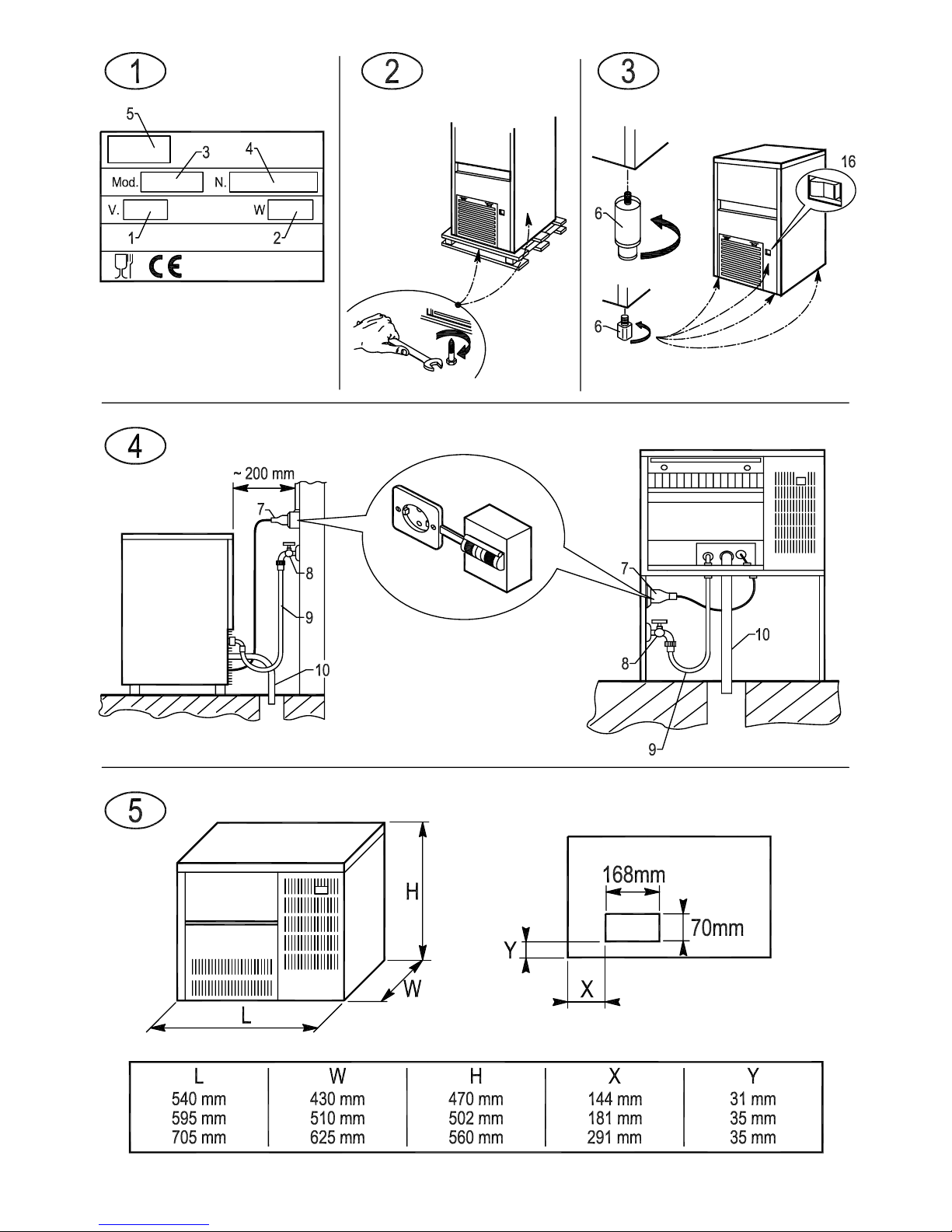
2 TECHNICAL DATA (Fig. 1)
The voltage and frequency are given on the data plate on the appliance. Refer to this data plate to
check compliance.
Voltage (1), power (2), model (3 ), serial No. (4), Manufacturer (5).
The weighted equivalent continuous sound level A of this appliance is less than 70 dB(A). The
measurements were made over an entire production cycle, at a distance of 1 m from the surface of the
appliance and at a height of 1.60 m from the floor.
The wiring diagram is stuck on the front counterpanel of the appliance.
In order to gain access thereto, unplug the appliance from the power source, loosen screws holding the
front panel, and slide it away after first opening the door.
3 ADVICE ABOUT TRANSPORTATION
The net weight and the weight including packaging of the appliance are given on the cover of this
instruction manual. Please refer to the instructions on the packaging in order to correctly transport and
lift the appliance.
To prevent the oil in the compressor from flowing back into the coolant circuit, always make sure that
the appliance is kept upright during transport, storage, and handling. Follow the instructions given on
the packaging.
4 UNPACKING
The appliance must be installed by authorized personnel, in compliance with the current laws in
force and the Manufacturer’s instructions.
Once you have removed the packaging according to the instructions on the box, MAKE SURE THAT
THE APPLIANCE IS IN A PERFECTLY GOOD CONDITION. IF IN DOUBT, DO NOT USE IT AND
IMMEDIATELY CONTACT THE DEAL E R who sold it to you.
All the packaging items (plastic bags, cardboard, polystyrene foam, nails, etc.) must be removed
and put out of the reach of children, as they are potential sources of danger.
Rest the wooden pallet on the floor and, using a hex socket wrench, loosen and remove the bolts (Fig. 2)
that fix the appliance to the pallet.
Lift the appliance using equipment fit to bear its weight. Separate the appliance from the wooden pallet
and fit the supplied legs into the housings on the base plate provided for the purpose (6 in Fig. 3).
Use a spirit level to ensure that the appliance is standing perfectly level. If necessary, adjust the legs.
5 INSTALLATION
5.1 CONNECTION DIAGRAM (Fig. 4)
7. electrical connection controlled by omnipolar circuit-breaker with residual current device
8. water tap
9. water supply pipe
10. water drainag
e pipe
Page 10

5.2 POSITIONING
‼ The appliance must be installed in a hygienically clean location; it is advisable to avoid
rooms like cellars and store-rooms, because failure to meet hygiene requirements is likely to
lead to the formation and prolif er ation of bacteria in the applia nc e .
The appliance can operate at an ambient temperature of between 10°C and 43°C.
The best performance will be obtained by installing the appliance in a place with an ambient
temperature of between 10°C and 35°C and a water temperature of between 3°C and 25°C.
Avoid direct exposure to sunlight and do not install near heat sources.
‼ This appliance:
• must be installed in a place where it can be supervised by skilled personnel
• must not be used outdoors
•
must not be installed in damp places or where it is liable to be sprayed with water
• must not be cleaned with jets of water
• must be positioned at a distance of at least 5 cm from the side walls (this does not apply to the
flush-mounting models)
5.
2.a POSITIONING FOR FLUSH-MOUNTING MODELS
Ventilation is ensured by the grille on the front panel; it is therefore not necessary to leave any gap,
except to facilitate installation.
A hole must be made in the surface where the appliance is to be located so that the power cable,
water supply pipe and the w a ter drain pipe can be passe d through as shown in Fig. 5.
The plug and water supply and drain connections are accessible from the front panel.
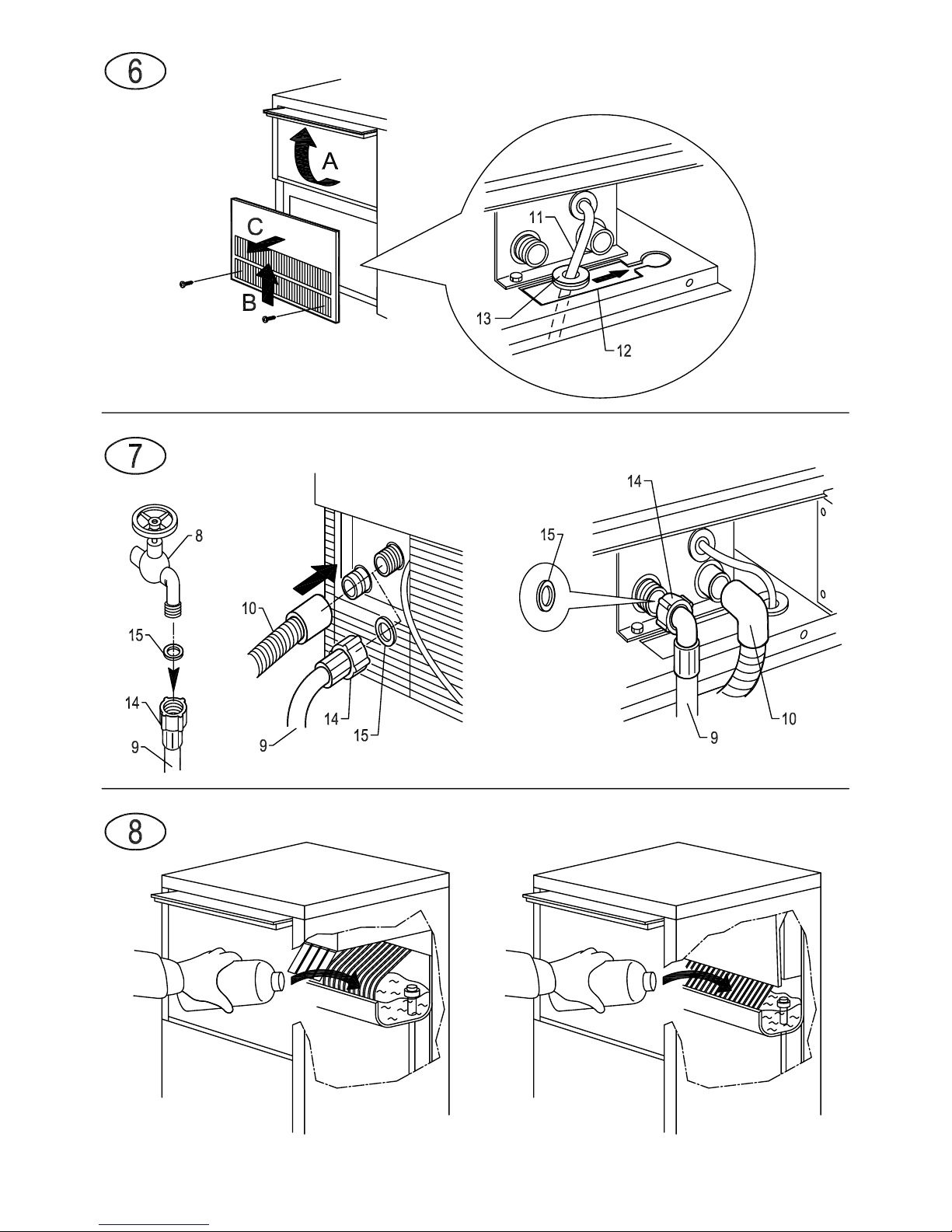
To access these, disconnect the appliance from the power supply, unscrew the screws that hold the
front panel in place and after opening the door, pull out the panel from above (Fig. 6).
Before fitting the appliance in place, the power cable must be fixed to the base plate as shown in
the diagram in Fig. 6:
• pass the plug and cable (11) through the hole (12) in the plate
• position the cable clamp (13) in its housing
Fit the front panel back in place after making these connections.
5.3 CONNECTION TO THE WATER MAINS
‼ IMPORTANT:
• the appliance must be connected to the water mains by professionally qualified personnel in
accordance with the Manufacturer’s instructions
• this appliance must be only be supplied with cold water for human consumption (drinking water)
• the operating pressure must be between 0.1 and 0.6 MPa
• a tap must be installed between the water mains and the feed pipe of the appliance, so that the
water supply may be shut off if necessary
• where the feed water is particularly hard, you are advised to install a softener. Any solid particles
(e.g. sand) may be eliminated by installing a mechanical filter, which must be periodically inspecte
d
and cleaned. These devices must comply with the standards in force in the Country of use
• never turn the water supply tap off when the appliance is working
5.3.a FILLING WITH WATER ( Fig. 7)
Inse
rt the special seals provided (15) in the two threaded ring nuts (14) of the water supply pipe (9)
supplied with the appliance.
Without exerting excessive force (otherwise the unions could crack), firmly tighten one of the
threaded ring nuts on the outlet of the solenoid valve located in the rear of the appliance (front for
t
he flush-mounting models). The other threaded ring nut must be screwed to the water tap (8);
this too must be provided with a thread.
Page 11

5.3.b DRAIN (Fig. 7)
Fix the water drain pipe ( 10) in the housing provided on the rear of the appliance (front for the
flush-mounting models). Make sure that:
• the pipe is a hose
•
the internal diameter is 22 mm, as required
• the water drain hose is not throttled at any point throughout its length
• the drain hose slopes downwards by at least 15%
It is advisable to drain the water straight into an open drain trap.
5.4 CONNECTION TO THE ELECTRICITY MAINS
‼ IMPORTANT:
• the appliance must be connected to the electricity mains by professionally qualified personnel in
accordance with the Manufacturer’s instructions
• before connecting the appliance to the electricity mains, make sure that the mains voltage ra
ting
corresponds to the value indicated on the rating plate
• make sure that the appliance is connected to an efficient earthing system
• make sure that the capacity of the power supply system suits the maximum power value indicated
on the rating plate of the appliance
• if the appliance comes supplied with a plug, prepare a socket controlled by an omnipolar circuitbreaker (7 in Fig. 4), with a contact-opening gap of not less than 3 mm, in accordance with national
safety standards currently in force. This switch must be equipped with fuses, with the associated
residual current device positioned in such a way as to be readily accessible. Insert the plug into the
socket controlled by the switch (7 in Fig. 4)
• the plug must only be replaced by professionally qualified and authorized personnel, and the new
plug must comply with current national safety standards
• if the appliance comes supplied without a plug and you wish to connect it permanently to the power
supply, prepare an omnipolar circuit-breaker (7 in Fig. 4), with a contact-opening gap of not less
than 3 mm, in accordance with national safety standards currently in force. This switch must be
equipped with fuses, with the associated residual current device positioned in such a way as to be
readily accessible. This operation must be carried out by a specialized technician
• make sure that you fully uncoil the power supply cable and check that it is not crushed in any way
• should the supply cable be damaged, it must be replaced by a specialized technician usin
g a
special cable available from the Manufacturer or from the Technical Service Centres
6 START-UP
6.1 CLEANING INTERNAL PARTS
The appliance will have already been cleaned in the factory. However, you are advised to wash the
internal parts again before using the appliance. Make sure that the power supply cable is unplugged
before carrying out the above cleaning operation.
See cleaning and sanitizing manual for information regarding cleaning operations.
For cleaning operations in general, use an ordinary detergent for washing dishes or a solution of water
and vinegar. Rinse thoroughly with plenty of cold water and remove any ice that may have been
produced during the first 5 cycles after cleaning, together with any ice present in the bin.
It is advisable to avoid using abrasive detergents or powders, since these might damage the finish.
6.2 START-UP
When you start up the appliance the first time, or when you start it up again after a long period at
a standstill, fill the basin manually with water (Fig. 8).
This filling operation must be carried out by opening the door, raising the flaps (if any) and pouring the
water directly into the internal basin.
In the cycles subsequent to the initial one, the appliance will be filled with water in a fully automatic way.
Page 12

Once the appliance has been correctly connected to the electricity mains, water mains and water drain
system, it can be started up as follows:
a) turn on the water supply tap (8 in Fig. 4)
b) insert the plug (if any) in the socket and switch on the power supply by means of the relative switch
fitted during the installation phase (7 in Fig.
4)
Switch on appliance by pressing the luminous switch (16 in Fig. 3).
For appliances that are connected permanently to the electricity mains, turn on by means of the switch
on the outside of the appliance, fitted during the installation phase.
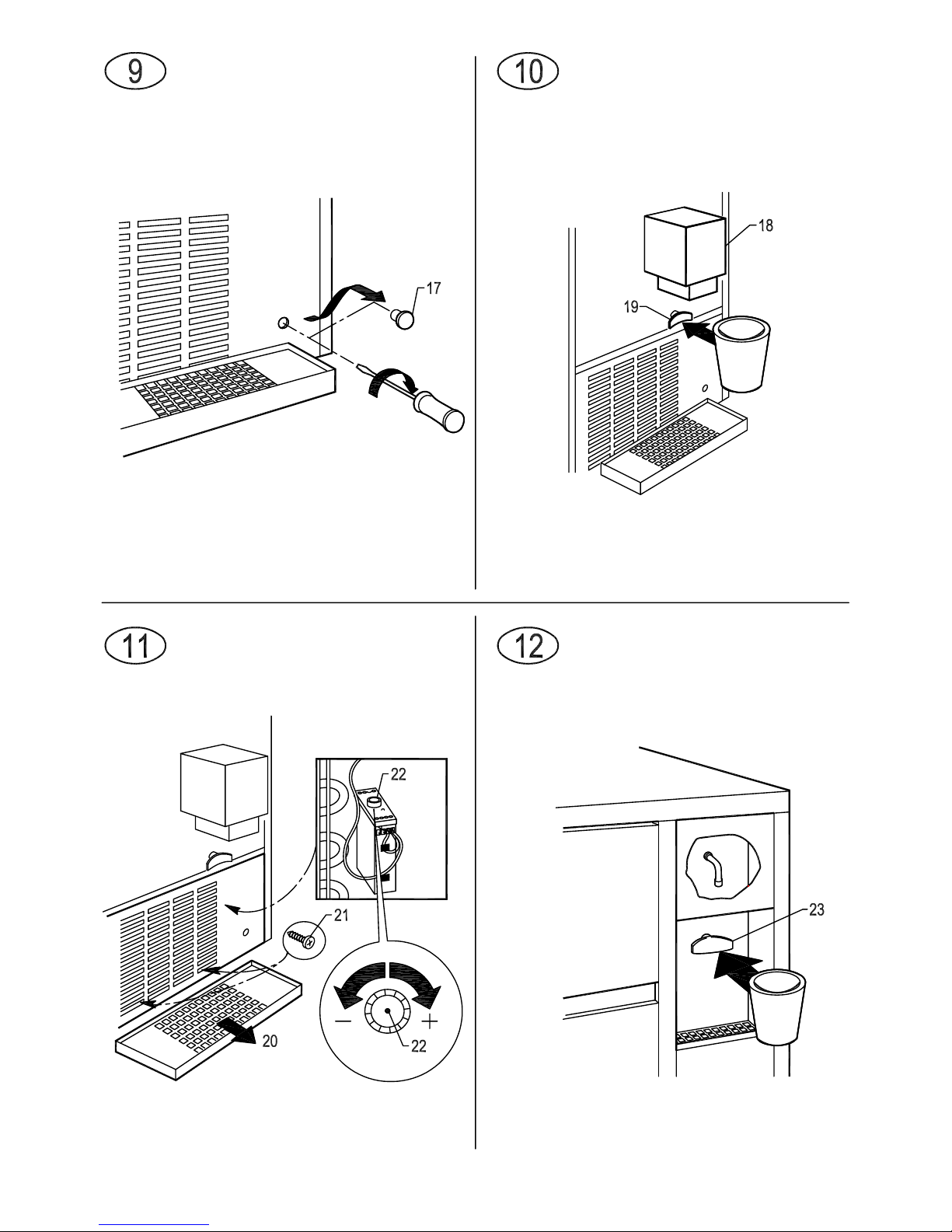
6.2.a STARTING UP MODELS WITH CONTINUOUS DELIVERY (Fig. 9)
Carry out operations a) and b) described above; then:
•
remove the plug (17) on the front grille pan
el
•
using a screwdriver turn the adjusting screw of the timer clockwise until you hear a click and the
water pump stops
• repeat the previous operation three times consecutively at intervals of one minute each
• when this operation has terminated, fit the plug (17) back on the front grille; the appliance will
automatically start producing ice
7 MAIN CAUSES OF OPERATING FAILURE
Should the appliance fail to produce ice, before calling on the Authorized Technical Service Centre, first
check carefull y t hat:
• the water supply tap (8 in Fig. 4), fitted during the installation phase, has been turned on
• electric power is reaching the appliance; the plug (if any) is properly inserted in the socket, the switch
(7 in Fig. 4) is in the “ON” position, and the push button (16 in Fig. 3) is lighted up
Furthermore:
• if there is excessive noise, make sure that the appliance is not touching furniture or sheet metal which
can give rise to noise or vibrations
• should any trace of water appear, check the drain hole of the container to ensure that it is not clogged,
that the water fill and drain pipes are correctly connected and are not throttled or damaged
• make sure that the temperature of the air or water does not exceed the installation limit values
(see paragraph 5.2)
• make sure that the water inlet filter is not clogged (see paragraph 9.1)
• make sure that the spray nozzles are not clogged with scaly deposits
If the fault still persists after the above inspections have been made, turn off the electric power source
by means of the switch fitted during the installation phase, pull out the plug from its socket, turn off the
tap connecting the appliance to the water mains, and contact the nearest Authorized Technical Service
Centre.
To obtain a faster and more efficient reply when you call the Centre, state the model of the appliance
precisely, together with its serial number or manufacturing number. This information is given on the
serial N° plate (Fig. 1) affixed to the rear of the appliance and on the cover of this instruction manual.
8 OPERATION
The appliance has a thermostat probe in the ice bin, which stops ice production when the ice
accumulated in the bin reaches the probe connected to the thermostat.
When ice is taken from the bin, the thermostat will automatically rea ctivate ice-cube production, thus
creating a new supply of ice.
8.1 MODEL WITH CONTINUOUS DELIVERY (Fig. 10)
The appliance is equipped with an ice-cube dispenser (18) on the front.
To take the required quantity of ice, place a glass or a suitable container under the dispenser and press
the button (19) to turn on the supply.
Page 13

8.1.a ADJUSTING DISPENSED QUANTITY (Fig. 11)
‼ IMPORTANT:
• the operations described below must be performed by a specialized technician, and only after
disconnecting the appliance from the electricity mains
• all operations that require handling of parts made of metal plate must be carried out wearing
suitable gloves to prevent cuts
The appliance is provided with an electronic device for adjusting the quantity of ice dispensed each
time.
To increase or decrease the dispensing time and the proportionate quantity of ice dispensed,
proceed as follows:
• remove the basin (20)
• slacken off the screws (21) on the front panel using a Phillips screwdriver
• pull out the front panel from above
•
turn the knob (22) on the electronic device clockwise to increase the quantity of ice dispensed
whenever the button is pressed, and anti-clockwise to reduce the quantity
8.2 MODEL WITH COLD WATER DISPENSER (Fig. 12)
The appliance is provided with a cold water dispenser located beside the ice bin.
To obtain cold water, place a glass under the outlet and gently press the button (23) to turn on the water
tap. Release the button to stop the flow of cold water.
If the appliance is already provided with a filter located on the cold water supply circuit, read the
instructions on the filter label carefully and follow the manufacturer’s recommendations regarding the
replacement schedules.
9 MAINTENANCE
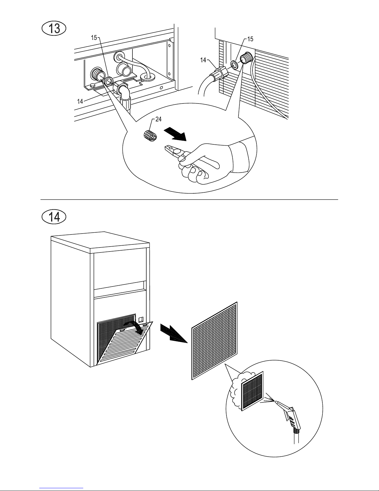
9.1 CLEANING THE FILTER OF WATER SUPPLY SOLENOID VALVE (Fig. 13)
!! At least every two months, clean the filter (24) located on the water inlet solenoid valve, proceeding
as follows:
• switch off the electric power supply by means of the switch (7 in Fig. 4), fit ted during installati on,
and disconnect the plug of the appliance from its socket (if any)
• shut off the water supply by turning the tap (8 in Fig. 4) fitted during installation
• unscrew the threaded ring nut (14) of the water feed hose, located at the outlet of the solenoid valve at
the rear of the appliance (front for the flush-mounting mode ls). For the built-in model, first remove
the panel as indicated at point 5.2.a
•
using a pair of pliers, remove the filter (24) from its seat without damaging the water feed pipe
connector
• place the filter under a strong jet of water to remove residue, but replace the filter if it is excessively
dirty
After having carried out the cleaning operations, refit the filter and hose pipe taking the necessary
precautions described earlier in the instruction manual.
When the operations have terminated, turn on both the electricity supply and wate r supply.
9.2 AIR-COOLED MODELS (Fig. 14)
For air-cooled models, it is very important to keep the finned condenser and its external filter (if any) clean.
Have the finned condenser cleaned at least once every two months by an Authorized Technical Service
Centre, which can include this operation in the scheduled maintenance programme.
The external filter (if any) must be cleaned at least once a month, as follows:
• switch of f app l ian ce an d cut off power supply with the switch (7 in Fig. 4) fitted at the installation stage
• open plastic grille
• remove filter and keep it at a distance form the appliance
•
remove dust from filter by blowing with compressed air
• replace filter in its seat and close plastic grille
Page 14

9.3 CLEANING AND SANITIZING OPERATIONS
A cleaning and sanitizing kit specifically designed for this appliance is available from your
dealer.
‼ Do not use corrosive substances to remove limescale from the appliance, because this will
invalidate the warranty, and may cause serious damage to the materials and components of the
appliance.
Do not use jets of water to clean the appliance.
‼ All cleaning operations must be carried out only after the electric power and water supplies
have been disconnected, as described previously, by professionally qualified and authorized
personnel.
Follow the instructions given in the cleaning and sanitizing manual supplied with the appliance.
‼ IMPORTANT:
All the ice produced during the first 5 cycles after cleaning and sanitizing operations, and any
ice already in the container, must be eliminated.
Complete sanitizing can only be carried out only by the Authorized Technical Service Centres, and must
be done regularly depending on the conditions of use of the appliance, the chemical and physical
features of the water, and after every period in which the appliance has remained at a standstill for any
length of time.
You are advised to ask your dealer to draw up a scheduled maintenance contract that will cover the
following:
• cleaning the condenser
• cleaning the filter located on the water supply solenoid valve
• cleaning the ice-tray
• checking the cha rge of coolant gas
•
checking the operating cycle
• sanitizing the appliance
10 PERIODS AT A STANDSTILL
If you do not intend to use the appliance for a certain period of time, proceed as follows:
• switch off the electric power source by means of the switch (7 in Fig. 4), and remove the plug of the
appliance from its socket (if any)
• shut off the water supply by turning off the water supply tap (8 in Fig. 4)
•
carry out all the operations envisaged for scheduled maintenance of the appliance (see chapter 9)
• empty the internal basin by raising the flaps (if any) and removing the overflow pipe
• empty out the pump body by blowing compressed air into the pipe that supplies water to the sprayer bank
• clean filter of water supply solenoid valve as described in chapter 9.1
•
clean filter of air condenser (if any) as described in chapter 9.2
Page 15

Page 16

Page 17

Page 18

Page 19

Page 20

Page 21

Page 22

Page 23

Page 24

Page 25

Page 26

Page 27

Page 28

Page 29

Check out Procedure for Service for CB
Anomaly THE ICE MAKER DOESN’T WORK
Cause Remedy
There is no supply mains voltage Check the user’s electrical system
Bin thermostat out of order Replace the bin thermostat
Safety thermostat of the water condenser out of
order
Replace the safety thermostat
Contactor out of order Replace the contactor
Anomaly THE ICE MAKER WORKS BUT THE ICE DOESN’T FORM
Cause Remedy
Overflow-tube in the bin not correctly positioned Check the right position
Ice maker without refrigerant Find the leak, repair it, make vacuum and charge
Refrigerant blow-by through the hot gas valve Clean the hot gas valve or replace it
Water blow-by through the evaporator water inlet
valve
Replace the valve
The compressor doesn’t compress Replace the compressor
For air-cooled models:
The fan is out of order
• Check the fan motor. If necessary, replace
it.
• Check the correct working of the pressure
switch
Anomaly THE ICE MAKER REMAINS WITHOUT WATER IN THE BASIN
Cause Remedy
No water supply to the ice maker Check the water supply
Overflow-tube in the bin not correctly positioned Check the right position
Water leakage from the pump Check and clamp the clips or replace the pump
Dirty spray nozzles Clean the spray nozzles
Faulty water inlet valve, it doesn’t open or is
clogged
Replace the water inlet valve
The timer doesn’t open the water inlet valve Replace the timer
Page 30

Anomaly
THE ICE MAKER REMAINS WITHOUT WATER IN THE MIDDLE OR AT
THE END OF THE CYCLE
Cause Remedy
Dirty spray nozzles Clean or replace the spray nozzles
Water leakage from the basin Check possible breakings
Filter of the water inlet valve clogged Clean the filter
Anomaly THE ICE MAKER DOESN’T SPRAY WATER
Cause Remedy
The pump is out of order
Check the electric and mechanical pump efficiency
or replace it
Filter of the pump suction clogged Clean the filter
Limestone inside the pump pipes Clean the pipes from the limestone
Spray nozzles clogged Clean the spray nozzles
Anomaly THE ICE MAKER DOESN’T STOP WHEN THE BIN IS FULL
Cause Remedy
Bin thermostat
Replace the thermostat or adjust it or check the
probe position
Anomaly
THE ICE MAKER STOPS BY INTERVENTION OF THE WATER
CONDENSER SAFETY THERMOSTAT / PRESSURE-SWITCH
(Water Leakage in the Condenser)
Cause Remedy
No water supply to the ice maker Check the water supply
The water inlet valve doesn’t open
• Check the correct working of the
thermostat / pressure-switch
• Check if the correct rated voltage reaches
the water inlet valve
• Replace the valve
Condenser clogged by limestone Remove the limestone from the condenser
Page 31

Anomaly THE ICE MAKER REMAINS IN THE DEFROSTING PHASE
Cause Remedy
Faulty evaporator thermostat Replace the evaporator thermostat
The hot gas valve doesn’t open
• Check the electric feeding
• Replace the valve coil
• Replace the valve
Timer locked Replace the timer
Anomaly NOT REGULAR OR INCOMPLETE DEFROSTING
Cause Remedy
Lack of water Check the right water flow to the evaporator
Lacking refrigerant charge Find the leak, repair it, make vacuum and charge
Evaporator encrusted by limestone
Remove the limestone from the whole evaporator,
but without roughening its surfaces
The water inlet valve of the water condenser
doesn’t close
• Replace the anti interference condenser
placed parallel to the pressure switch
• Replace the valve
Anomaly SHEET OF ICE UNDER THE EVAPORATOR
Cause Remedy
Faulty or not adjusted evaporator thermostat Replace the evaporator thermostat or adjust it
Refrigerant blow-by through the hot gas valve Clean or replace the valve
Timer locked Replace the timer
Ice maker without refrigerant Find the leak, repair it, make vacuum and charge
Page 32

Anomaly WATER LEAKAGES
Cause Remedy
Inlet or outlet pipe not connected Check connections
The pump is leaking Replace the pump
Slack pipe clips Check the clamp of the clips
The bin water-outlet joint is slack or badly
connected
Check or fasten
Anomaly IRREGULAR OR OPAQUE ICE CUBE
Cause Remedy
Water supply too calcareous
Spray nozzles badly lined up or dirty
Clean or direct the water jet toward the middle of
the ice cubes
Anomaly
COMPRESSOR: PROTECTION INTERVENTION
(Intermittent Working)
Cause Remedy
Faulty power supply
Check:
• continuity,
• the current carrying in Amp.,
• voltage of the electrical circuit.
Difficult condensation
Check:
• cleaning of the condenser and of the filter,
• the fan working,
• aeration in and out of the ice maker.
Starting capacitor out of order Replace the capacitor
Compressor starting relay out of order Replace the relay
Compressor winding discontinued Replace the compressor
Seizing Replace the compressor
Page 33

Anomaly NOISY COMPRESSOR
Cause Remedy
Extreme mechanical wear Replace the compressor
Anomaly NOISY PUMP
Cause Remedy
Worn bearings Replace the pump
Plate fixing Fasten the screws
Anomaly THE PUMP LEAKS WATER
Cause Remedy
Slack pipe-clips Check and clamp the clips
Worn ceramic seal Replace the pump
External gasket broken Replace the pump
Anomaly THE PUMP DOESN’T RUN
Cause Remedy
Lack of power supply Check the contacts of the timer micro-switch
Lack of power Replace the run capacitor
Mechanical locking Replace the pump
Interrupted winding Replace the pump
Page 34

Anomaly INTERVENTION OF THE USER’S MAIN SWITCH
Cause Remedy
Compressor: short circuit and/or low dielectric
strength
Replace the component
Pump: short circuit and/or low dielectric strength Replace the component
Hot gas valve: short circuit and/or low dielectric
strength
Replace the component
Thermostat: low dielectric strength Replace the component
Other electrical components: short circuit and/or
low dielectric strength
Replace the component
Anomaly ICE PRODUCTION DECREASE
Cause Remedy
Condenser or air filter clogged Clean the filter and the condenser
Bin flooded Check the water outlet pipes
Ice maker without refrigerant Find the leak, repair it, make vacuum and charge
Refrigerant blow-by through the hot gas valve Clean the valve or replace it
Water blow-by through the evaporator water inlet
valve
Replace the valve
The compressor doesn’t compress Replace the compressor
Page 35

ICE CUBE MAKERS “SPRAYERS” SYSTEM
Last Update: 04/04/2011
C
C
C
B
B
B
L
L
L
i
i
i
n
n
n
e
e
e
The following diagram shows the main concepts of the ice cube
makers working (‘sprayers’ system).
Compressor
Condenser
Air
Water
Evaporator
Each ice maker uses the properties of compression and
expansion of the liquefiable gases; its main principle is that each
change of bodies state is got by producing or absorbing heat.
The compressor sucks up the gases, generated by the
evaporation, and compresses them, increasing their
temperature and pressure.
A condenser, made up of a series of tubes (refrigerated by
cold water or ventilated air), carries away the heat, comprised in
the gas from the compressor and helps, in this way, the gas
liquefaction.
The refrigerating fluid, now in liquid state, circulates, then, in an
evaporator that permits an optimal heat exchange with the outroom, by taking away calories and producing ice, which is got by
means of the freezing of the water sprayed in the cubes forms
by the spray-bar.
The working of this machine is cyclical: ice cubes are produced
during the first phase and fall in the built-in bin during the
second phase.
Page 36

R
R
R
e
e
e
f
f
f
r
r
r
i
i
i
g
g
g
e
e
e
r
r
r
a
a
a
t
t
t
i
i
i
n
n
n
g
g
g
C
C
C
i
i
i
r
r
r
c
c
c
u
u
u
i
i
i
t
t
t
The working of this machine is cyclical. Each cycle is divided into
two phases: ice cubes are produced during the first phase and fall
in the built-in bin during the second phase.
The following diagram shows the main concepts of the
refrigerating circuit:
Hot gas
valve
Suction line
Capillar Tube
Condenser
(Water)
Condenser
(Air)
Refrigerating
filter
Compressor
Evaporator
Cubes basin
Production Phase of the Ice Cubes
The hot gas valve is closed; the refrigerating fluid
, after
having been cooled by the condenser, circulates through the
evaporator coil (welded to the cubes basin), and cools each
small copper cup.
Water is sprayed on the evaporator cubes-basin through the
spray-bar nozzles. An ice layer, due to the refrigerating fluid,
begins to form in the cups, till these are completely full (after
some minutes).
Ice Falling Phase (Defrosting)
Once the ice-production time is finished, the spray-
bar stops
spraying water on the cubes-basin and the hot gas valve,
assembled on the compressor delivery side, opens.
This opening permits to pipe the refrigerating fluid (now
overheated, after the compression) directly to the evaporator,
without letting it pass through the condenser.
Due to such overheated fluid, the evaporator warms up and
the ice cubes formed in the cups, fall in the bin below.
At the end of the defrosting phase, the cycle starts again.
The compressor is always working: during both the production
and the defrosting phase.
Page 37

R
R
R
e
e
e
f
f
f
r
r
r
i
i
i
g
g
g
e
e
e
r
r
r
a
a
a
t
t
t
i
i
i
n
n
n
g
g
g
C
C
C
i
i
i
r
r
r
c
c
c
u
u
u
i
i
i
t
t
t
(
(
(
C
C
C
o
o
o
m
m
m
p
p
p
o
o
o
n
n
n
e
e
e
n
n
n
t
t
t
s
s
s
)
)
)
Compressor
It sucks up the gases, generated by the evaporator by means of
a suction line and compresses them, increasing their
temperature and pressure.
Hot Gas Valve
It controls a circuit that starts from the compresso
r and arrives to
the evaporator, bypassing the condenser.
The opening of the valve permits to pipe the refrigerating fluid
(overheated after the compression) directly to the evaporator,
without letting it pass through the condenser thus warming up
the evaporator.
Condenser (Air/Water)
If ‘Water’, it is made up of a series of tubes, ref
rigerated by cold
water.
If ‘Air’, it is made up of a radiator, that exchanges heat with the
out-room, and is refrigerated by air, coming from a fan, run by
an electric motor.
Both of them carry away the heat, comprised in the gas that
comes out from the compressor, helping, in this way, the gas
liquefaction.
Refrigerating Filter + Capillar Tube
The refrigerant filter stops possible impurities and
the circuit
humidity.
The gas, in liquid status, goes to the evaporator through this
filter and the capillar tube.
Evaporator
It permits an optimal heat exchange with the water s
prayed on it
and produces ice by means of the water freezing.
It is made by a series of small tin plated cups, plunged into a
plastics support and welded to a copper coil, where the
refrigerating gas circulates.
Suction line
It permits the refrigerating gas circulation from th
e evaporator to
the compressor.
The suction line also controls and keeps constant the circulation
of the gas, coming out from the evaporator.
The liquid gas is trapped in a specific expansion boiler, that
prevents its arrival to the compressor.
Page 38

R
R
R
e
e
e
f
f
f
r
r
r
i
i
i
g
g
g
e
e
e
r
r
r
a
a
a
t
t
t
i
i
i
n
n
n
g
g
g
C
C
C
i
i
i
r
r
r
c
c
c
u
u
u
i
i
i
t
t
t
(
(
(
P
P
P
r
r
r
o
o
o
d
d
d
u
u
u
c
c
c
t
t
t
i
i
i
o
o
o
n
n
n
C
C
C
y
y
y
c
c
c
l
l
l
e
e
e
)
)
)
Ice cubes production
The hot gas valve is closed; the compressed gas from the
compressor, is piped to the condenser in order to get cool.
Hot gas
valve
Closed
Suction line
Capillar Tube
Condenser
(Water)
Condenser
(Air)
Refrigerating
filter
Compressor
Evaporator
Cubes basin
Defrosting
The hot gas valve is open; the compressed gas from t
he
compressor, is piped to the evaporator, bypassing the
condenser.
Hot gas
valve
Open
Suction line
Capillar Tube
Condenser
(Water)
Condenser
(Air)
Refrigerating
filter
Compressor
Evaporator
Cubes basin
Page 39

H
H
H
y
y
y
d
d
d
r
r
r
a
a
a
u
u
u
l
l
l
i
i
i
c
c
c
C
C
C
i
i
i
r
r
r
c
c
c
u
u
u
i
i
i
t
t
t
The following diagram shows the main concepts of the hydraulic
circuit:
Evaporator
Water-inlet
valve
Water
Supply
Water-inlet
valve
Water
Drain
Water
Condenser
Spray-bar
Pump
Overflow tube
Water Basin
CB1565 ONLY
Pressostatic
Valve
The water supply circuit of the basin, the water-inlet valve, the
pump and the evaporator are on all machines of the ‘CB’-line;
the water condenser circuit, on the contrary, is on water-cooled
versions only.
Water-inlet valve
It works during the defrosting phase and allows the
water to flow
on the evaporator, having two goals: 1st. one is to warm the
evaporator help, in this way, the ice cubes detaching; 2nd. one,
the water falls into the basin, restores the ideal level to start a
new production cycle.
The second water-inlet valve allows the water flow of the
through the water condenser.
Water basin
It gets water from the water mains. It feeds the pum
p by a
specific pipe provided with a filter.
Pump
It draws out water from the water basin and pipes it
, under
pressure, to the spray-bar.
Spray-bar
It gets water from the pump and, by means of its nozzles,
sprays it towards the cubes basin of the evaporator. The water
that does not freeze, by contacting the cups (refrigerated by the
evaporator coil), falls in the inside bin and is drawn by the pump
once again.
Overflow tube
It is a floodway. All the surplus water, entering in
to the water
basin, comes out from it.
Pressostatic valve (CB1565 only)
It is assembled only on water cooled machines.
I
t controls and keeps constant the condensing pressure, by
changing the quantity of water that flows in the condenser.
Page 40

E
E
E
l
l
l
e
e
e
c
c
c
t
t
t
r
r
r
i
i
i
c
c
c
C
C
C
i
i
i
r
r
r
c
c
c
u
u
u
i
i
i
t
t
t
The following diagram shows the main concepts of the electric
circuit:
Compressor
Condenser
Pressure switch
Bin
thermostat
Evaporator
thermostat
Hot gas
valve
Water-inlet
valve
(Evaporator)
Pump
Fan
Water-inlet
valve
(Condenser)
Safety
thermostat
no on CB1565W
Timer
Contactor - ONLY CB1565
H.P. Pressure switch - Only CB1565
The ice maker is energized by the bin thermostat, that stops
machine when the bin is full.
The timer is designed in such a way that it is connected
upstream the bin thermostat during the ice production phase, so
that the ice maker will stop only when the ice production phase
is over.
The following scheme shows this working system:
Timer
Utilizer
Unit
Bin thermostat
Only in the ice
production phase
NB: some components of the electrical circuit (called Utilizer
Units) are always energized and do not depend on the timer
status. See the following table:
““WWaatteerr”” mmaacchhiinneess
Condenser
pressure-switch
Compressor
Water-inlet
valve
(Condenser)
LINE
CCBB 224466 ÷÷ 442255 ““AAiirr””
Compressor
LINE
CCBB 664400 ÷÷ 11226655 ““WWaatteerr””
Condenser
pressure-switch
Compressor
Refrigerating
fan
LINE
For CB1565 the contactor energized the compressor.
Page 41

E
E
E
l
l
l
e
e
e
c
c
c
t
t
t
r
r
r
i
i
i
c
c
c
C
C
C
i
i
i
r
r
r
c
c
c
u
u
u
i
i
i
t
t
t
(
(
(
T
T
T
i
i
i
m
m
m
e
e
e
r
r
r
S
S
S
t
t
t
a
a
a
t
t
t
u
u
u
s
s
s
)
)
)
Ice cubes production
The timer, in the first phase, starts up the pump and the utilizer
units, as described in the scheme of the previous page.
Timer
Evaporator
thermostat
Pump
Utilizer
Unit
Some minutes after the beginning of the ice production phase,
due to the refrigerant in expansion in the coil, an ice layer starts
to form inside the cups; the evaporator thermostat, perceiving a
drop in temperature of the evaporator, starts the timer, in order
to complete the ice production phase.
Defrosting
The timer, once reached the set up time, simultaneou
sly
commutes three contacts, letting the defrosting phase begin.
Evaporator
thermostat
Timer
Hot gas
valve
Water-inlet
valve
(Evaporator)
The pump is stopped and also the spray noozles stop; on the
contrary, the hot gas valve is started in order to pipe the
refrigerating fluid (overheated) directly to the evaporator.
The water inlet valve opens and allows the water to flow from
water mains into the basin.
The evaporator thermostat, perceiving a temperature rise (due
to the circulation of hot fluid), starts up the timer again, so to
complete the defrosting phase.
Page 42

E
E
E
l
l
l
e
e
e
c
c
c
t
t
t
r
r
r
i
i
i
c
c
c
C
C
C
i
i
i
r
r
r
c
c
c
u
u
u
i
i
i
t
t
t
(
(
(
C
C
C
o
o
o
m
m
m
p
p
p
o
o
o
n
n
n
e
e
e
n
n
n
t
t
t
s
s
s
)
)
)
Controls systems
Hot gas valve – The opening of the valve permits to pipe the
refrigerating fluid (overheated after the compression) directly to
the evaporator, without letting it pass through the condenser
thus warming up the evaporator.
Evaporator thermostat – It feels the evaporator temperature
and drives the timer, as previuosly described.
Condenser pressure-switch – It controls and keeps constant
the condensing pressure; it drives the refrigerating fan, it drives
the condenser water inlet valve.
Timer – See next page.
Water-inlet valve (evaporator) – It is open during the
defrosting phase, allowing the water to flow on the evaporator
and, then, into the water basin, to restore the ideal water level to
start a new cycle of ice cubes production.
Water-inlet valve (condenser) – This second water-inlet valve
allows the water to flow through the water condenser.
Contactor – Energized the compressor.
Safety systems
Safety thermostat – Placed on the condenser of the water
models.
It stops the machine working, when the temperature of the water
condenser exceeds a preset threshold value.
Bin thermostat - The bin thermostat stops the ice machine
when it perceives a drop in temperature due to the ice cubes
accumulation in the bin.
The machine only stops during the defrosting phase, as the
timer keeps a second power source active during the production
phase till the phase commutation.
H. P. Safety Presssure switch – It stops the machine working,
when the condensation pressure exceeds the preset threshold
value.
Page 43

W
W
W
o
o
o
r
r
r
k
k
k
i
i
i
n
n
n
g
g
g
S
S
S
c
c
c
h
h
h
e
e
e
m
m
m
e
e
e
C
C
C
B
B
B
2
2
2
4
4
4
6
6
6
÷
÷
÷
4
4
4
2
2
2
5
5
5
(
(
(
A
A
A
i
i
i
r
r
r
V
V
V
e
e
e
r
r
r
s
s
s
i
i
i
o
o
o
n
n
n
)
)
)
Hydraulic Circuit
Refrigerating Circuit
Electric Circuit
LINE
CAMME 4
CAMME 3
CAMME 2 CAMME 1
EVAPORATOR
THERMOSTAT
BIN
THERMOSTAT
TIMER
MOTOR
CONDENSER
CAPILLAR
TUBE
COMPRESSOR
HOT
GAS
VALVE
SUCTION
LINE
NEUTRAL
WATER
INLET
VALVE
WATER
SUPPLY
PUMP
EVAPORATOR
+ SPRAY BAR
OVERFLOW
TUBE
GREEN LIGHT SWITCH
(on-off)
GREEN LIGHT SWITCH
(on-off)
Page 44

W
W
W
o
o
o
r
r
r
k
k
k
i
i
i
n
n
n
g
g
g
S
S
S
c
c
c
h
h
h
e
e
e
m
m
m
e
e
e
C
C
C
B
B
B
2
2
2
4
4
4
6
6
6
÷
÷
÷
4
4
4
2
2
2
5
5
5
(
(
(
W
W
W
a
a
a
t
t
t
e
e
e
r
r
r
V
V
V
e
e
e
r
r
r
s
s
s
i
i
i
o
o
o
n
n
n
)
)
)
Hydraulic Circuit
Refrigerating Circuit
Electric Circuit
LINE
SAFETY
THERMOSTAT
EVAPORATOR
THERMOSTAT
BIN
THERMOSTAT
CAMME 4 CAMME 3
CAMME 2
CONDENSER
PRESSURE-SWITCH
CONDENSER
WATER
DRAIN
WATER
INLET
VALVE
WATER
SUPPLY
SUCTION
LINE
NEUTRAL
COMPRESSOR
CAMME 1
TIMER
MOTOR
CAPILLAR
TUBE
WATER
SUPPLY
WATER
INLET
VALVE
PUMP
HOT GAS
VALVE
EVAPORATOR
+ SPRAY BAR
OVERFLOW
TUBE
GREEN LIGHT SWITCH
(ON-OFF)
GREEN LIGHT SWITCH
(ON-OFF)
Page 45

W
W
W
o
o
o
r
r
r
k
k
k
i
i
i
n
n
n
g
g
g
S
S
S
c
c
c
h
h
h
e
e
e
m
m
m
e
e
e
C
C
C
B
B
B
6
6
6
4
4
4
0
0
0
÷
÷
÷
1
1
1
2
2
2
6
6
6
5
5
5
(
(
(
A
A
A
i
i
i
r
r
r
V
V
V
e
e
e
r
r
r
s
s
s
i
i
i
o
o
o
n
n
n
)
)
)
Hydraulic Circuit
Refrigerating Circuit
Elctric Circuit
LINE
CAMME 4
CAMME 3
CAMME 2
CAPILLAR
TUBE
CONDENSER
CONDENSER
PRESSURE-SWITCH
COMPRESSOR
HOT GAS
VALVE
SUCTION LINE
NEUTRAL
FAN
CAMME 1
TIMER
MOTOR
EVAPORATOR
THERMOSTAT
BIN
THERMOSTAT
WATER
INLET
VALVE
WATER
SUPPLY
PUMP
EVAPORATOR
+ SPRAY BAR
OVERFLOW
TUBE
GREEN LIGHT SWITCH
ON-OFF
GREEN LIGHT SWITCH
ON-OFF
Page 46

W
W
W
o
o
o
r
r
r
k
k
k
i
i
i
n
n
n
g
g
g
S
S
S
c
c
c
h
h
h
e
e
e
m
m
m
e
e
e
C
C
C
B
B
B
6
6
6
4
4
4
0
0
0
÷
÷
÷
1
1
1
2
2
2
6
6
6
5
5
5
(
(
(
W
W
W
a
a
a
t
t
t
e
e
e
r
r
r
V
V
V
e
e
e
r
r
r
s
s
s
i
i
i
o
o
o
n
n
n
)
)
)
Hydraulic Circuit
Refrigerating Circuit
Electric Circuit
LINE
SAFETY
THERMOSTAT
CONDENSER
PRESSURE-SWITCH
CONDENSER
CAMME 4 CAMME 3
CAMME 2 CAMME 1
TIMER
MOTOR
WATER
DRAIN
WATER
INLET
VALVE
WATER
SUPPLY
NEUTRAL
SUCTION
LINE
COMPRESSOR
EVAPORATOR
THERMOSTAT
BIN
THERMOSTAT
CAPILLAR
TUBE
WATER
SUPPLY
WATER
INLET
VALVE
PUMP
HOT GAS
VALVE
EVAPORATOR
+ SPRAY BAR
OVERFLOW
TUBE
GREEN LIGHT SWITCH
ON-OFF
GREEN LIGHT SWITCH
ON-OFF
Page 47

W
W
W
o
o
o
r
r
r
k
k
k
i
i
i
n
n
n
g
g
g
S
S
S
c
c
c
h
h
h
e
e
e
m
m
m
e
e
e
C
C
C
B
B
B
1
1
1
5
5
5
6
6
6
5
5
5
(
(
(
A
A
A
i
i
i
r
r
r
V
V
V
e
e
e
r
r
r
s
s
s
i
i
i
o
o
o
n
n
n
)
)
)
Hydraulic Circuit
Refrigerant Circuit
Electric Circuit
LINE
CAMME 4
CAMME 3
CAMME 2
CAPILLARY
TUBE
CONDENSER
PRESSURE SWITCH
CONDENSER
COMPRESSOR
HOT GAS
VALVE
SUCTION
LINE
NEUTRAL
FAN
CAMME 1
TIMER
MOTOR
EVAPORATOR
THERMOSTAT
BIN
THERMOSTAT
WATER
INLET
VALVE
WATER
SUPPLY
PUMP
EVAPORATOR
+ SPRAYERS
BAR
OVERFLOW
PIPE
GREEN LIGHT
SWITCH ON-OFF
CONTACTOR
CONTACTOR
COIL
CONTACTOR
HP SAFETY PRESSURE SWITCH
GREEN LIGHT
SWITCH ON-OFF
Page 48

W
W
W
o
o
o
r
r
r
k
k
k
i
i
i
n
n
n
g
g
g
S
S
S
c
c
c
h
h
h
e
e
e
m
m
m
e
e
e
C
C
C
B
B
B
1
1
1
5
5
5
6
6
6
5
5
5
(
(
(
W
W
W
a
a
a
t
t
t
e
e
e
r
r
r
V
V
V
e
e
e
r
r
r
s
s
s
i
i
i
o
o
o
n
n
n
)
)
)
LINE
HP SAFETY
PRESSURE SWITCH
CONDENSER
CAMME 4 CAMME 3
CAMME 2 CAMME 1
TIMER
MOTOR
WATER
OUTLET
PRESSOSTATIC
VALVE
WATER
INLET
NEUTRAL
SUCTION
LINE
COMPRESSOR
EVAPORATOR
THERMOSTAT
BIN
THERMOSTAT
CAPILLARY
TUBE
WATER
INLET
WATER
INLET
VALVE
PUMP
HOT GAS
VALVE
EVAPORATOR
+ SPRAYER
BAR
OVERFLOW
PIPE
CONTACTOR
CONTACTOR
COIL
CONTACTOR
Hydraulic Circuit
Refrigerant Circuit
Electric Circuit
GREEN LIGHT
SWITCH ON-OFF
GREEN LIGHT
SWITCH ON-OFF
 Loading...