

Page 1
DIAMOND
P R O D U C T S
HYDRAULIC CHAIN SAW
MODEL HCH50
OPERATOR MANUAL
September 2009
Part # 1801446
Page 2

Manufacturer’s address:
TYROLIT Hydrostress AG
Witzbergstrasse 18
CH-8330 Pfäffikon
Switzerland
Telephone +41 (0) 44 / 952 18 18
Fax +41 (0) 44 / 952 18 00
Operating instructions
TYROLIT Hydrostress AG reserves the right to make technical changes
without prior notice.
Copyright © 2003 TYROLIT Hydrostress AG, CH-8330 Pfäffikon ZH
All rights reserved, in particular copying and translation rights.
Reprinting of extracts from this safety manual is prohibited. No parts may
be reproduced or processed, copied or distributed using an electronic
system, in whatever form, without the written permission of TYROLIT
Hydrostress AG.
10984695 en / 7.8.07
Page 3

Operating instructions Overview
Overview
Page
0 Introduction 1
0.1 Congratulations!- - - - - - - - - - - - - - - - - - - - - - - - - - - - - - - 1
0.2 Validity of these Operating instructions- - - - - - - - - - - - - - - 2
0.3 Standards - - - - - - - - - - - - - - - - - - - - - - - - - - - - - - - - - - - 2
0.4 Delimitation of the system- - - - - - - - - - - - - - - - - - - - - - - - 2
1 Product description 1
1.1 Important information on the Chain saw HCH5011 - - - - - - 1
1.2 Technical data - - - - - - - - - - - - - - - - - - - - - - - - - - - - - - - - 4
1.3 Accessories- - - - - - - - - - - - - - - - - - - - - - - - - - - - - - - - - - 9
1.4 Scope of supply - - - - - - - - - - - - - - - - - - - - - - - - - - - - - - - 9
2 Safety instructions 1
2.1 General- - - - - - - - - - - - - - - - - - - - - - - - - - - - - - - - - - - - - 1
2.2 Safety principles - - - - - - - - - - - - - - - - - - - - - - - - - - - - - - 2
2.3 General safety rules- - - - - - - - - - - - - - - - - - - - - - - - - - - - 3
2.4 Information and symbols- - - - - - - - - - - - - - - - - - - - - - - - - 5
2.5 Generally applicable warnings of residual dangers - - - - - - 6
2.6 Responsibility - - - - - - - - - - - - - - - - - - - - - - - - - - - - - - - - 7
3 Design and function 1
3.1 Design - - - - - - - - - - - - - - - - - - - - - - - - - - - - - - - - - - - - - 1
3.2 Function - - - - - - - - - - - - - - - - - - - - - - - - - - - - - - - - - - - - 1
3.3 Component description- - - - - - - - - - - - - - - - - - - - - - - - - - 2
4 Controls and displays 1
4.1 Controls - - - - - - - - - - - - - - - - - - - - - - - - - - - - - - - - - - - - 1
4.2 Displays - - - - - - - - - - - - - - - - - - - - - - - - - - - - - - - - - - - - 1
5 Putting into operation 1
6Operation 1
6.1 General- - - - - - - - - - - - - - - - - - - - - - - - - - - - - - - - - - - - - 1
6.2 System requirements - - - - - - - - - - - - - - - - - - - - - - - - - - - 5
6.3 Preparatory operations - - - - - - - - - - - - - - - - - - - - - - - - - - 5
6.4 Working with the Chain saw HCH5011- - - - - - - - - - - - - - - 10
6.5 After the work - - - - - - - - - - - - - - - - - - - - - - - - - - - - - - - - 12
7 Maintenance 1
7.1 General- - - - - - - - - - - - - - - - - - - - - - - - - - - - - - - - - - - - - 1
7.2 Maintenance and servicing table - - - - - - - - - - - - - - - - - - - 3
8 Servicing 1
8.1 General- - - - - - - - - - - - - - - - - - - - - - - - - - - - - - - - - - - - - 1
8.2 Tensioning the diamond chain- - - - - - - - - - - - - - - - - - - - - 3
8.3 Changing the diamond chain- - - - - - - - - - - - - - - - - - - - - - 4
8.4 Changing the bar - - - - - - - - - - - - - - - - - - - - - - - - - - - - - - 5
8.5 Changing the drive wheel - - - - - - - - - - - - - - - - - - - - - - - - 6
8.6 Troubleshooting- - - - - - - - - - - - - - - - - - - - - - - - - - - - - - - 7
HCH5011 / 001 I (II)
Page 4

Overview Operating instructions
9 Taking out of service and storage 1
9.1 Taking out of service- - - - - - - - - - - - - - - - - - - - - - - - - - - - 1
9.2 General - - - - - - - - - - - - - - - - - - - - - - - - - - - - - - - - - - - - - 1
9.3 Storage - - - - - - - - - - - - - - - - - - - - - - - - - - - - - - - - - - - - - 2
10 Transport, Packing 1
10.1 Transport - - - - - - - - - - - - - - - - - - - - - - - - - - - - - - - - - - - - 1
10.2 Packing - - - - - - - - - - - - - - - - - - - - - - - - - - - - - - - - - - - - - 1
11 Disposal 1
11.1 General - - - - - - - - - - - - - - - - - - - - - - - - - - - - - - - - - - - - - 1
11.2 Disposal regulations - - - - - - - - - - - - - - - - - - - - - - - - - - - - 2
11.3 Disposal of the Chain saw HCH5011 - - - - - - - - - - - - - - - - 2
II (II) HCH5011 / 001
Page 5

Operating instructions Introduction
0 Introduction
0.1 Congratulations!
You have decided to buy an advanced, tried and tested Hydrostress
system and have thus acquired a highly sophisticat ed and reliable state-ofthe-art unit.
Thanks to the stress we place on quality assurance, your Hydrostress
system is another top-of-the-range Swiss product:
• High performance
• Reliable operation
• High portability
• Easy handling
• Low maintenance costs
Only original Hydrostress spare parts ensure quality and
interchangeability.
In the case of neglected or inappropriate ma intenance, we refuse to accept
any warranty commitment as specified in our terms of delivery.
Any repair work is to be carried out by trained personnel only.
Should you need more details concerning your Hydrostress system in
order to keep it in perfect condition, please cont act our af ter-sales se rvice
for further information.
We hope that you will not experience any problems while working with your
Hydrostress system.
TYROLIT Hydrostress AG
Management
Copyright © Hydrostress, Jan. 2003
TYROLIT Hydrostress AG
Witzbergstrasse 18
CH-8330 Pfäffikon
Switzerland
Telephone +41 (0) 44 / 952 18 18
Fax +41 (0) 44 / 952 18 00
HCH5011 / 001 0-1
Page 6

Introduction Operating instructions
0.2 Validity of these operating instructions
These operating instructions are only valid for the following system:
Chain saw HCH5011
0.3 Standards
These operating instructions have been prepared in accordance with
CE Machinery Directive Appendix I and with the relevan t standards in force
at the time of printing.
0.4 Delimitation of the system
These operating instructions describe the use of the Chain saw HCH5011.
0-2 HCH5011 / 001
Page 7
Operating instructions Product description
1 Product description
1.1 Important information on the Chain saw
HCH5011
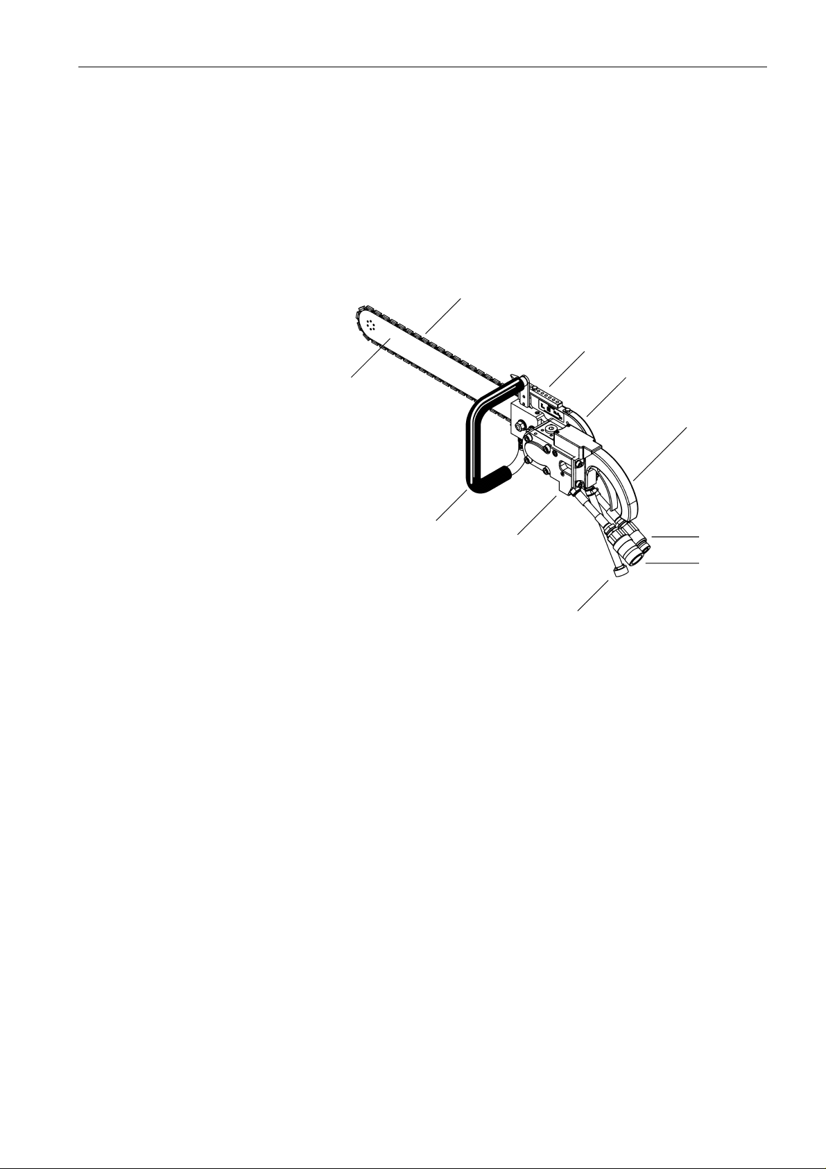
1.1.1 Main components
2
5
6
1
7
3
Fig. 1-1 Main components
1 Bar 7 Operating handle with manual starter
2 Chain 8 Coupling FD (flow)
3 T-handle 9 Hose stem (water)
4 Valve block 10 Nipple FD (return)
5 Cutting mandrel
6 Chain guard
4
10
8
9
HCH5011 / 001 1-1
Page 8

Product description Operating instructions
1.1.2 Intended purpose
The Chain saw HCH5011 is designed and built for the following
application:
• Cutting of concrete (including reinforced), masonry and natural stone
• Cutting of severance cuts, flush cuts and cross-cuts in ceilings, floors
and walls
• Only original TYROLIT Hydrostress AG tools (chains) should be used
The information provided in Chapter 1 “Technical Data” 1.2, 1-4
represents the mandatory usage limits and rated data
1.1.2.1 Safety measures
Any use other than for the intended purpose (see Chapter 1.1.2, 1-2)
constitutes improper use or misuse.
Since improper use or misuse can sometimes results in considerable
danger, here details of what we believe constitutes improper use or
misuse.
The following applications are prohibited:
• Cutting without the safety devices provided
• Cutting wood, glass and plastics
• Cutting without system and tool cooling
• Cutting in explosion-protected areas
• Cutting loose parts
• Incorrect or absence of waste water disposal (saw sludge)
1.1.3 Workplace and danger areas
Allow enough room for manoeuvre to ensure danger-free working.
Make sure you have sufficient lighting at your workplace.
Clearly cordon off the danger area so that no person can enter the danger
area during sawing.
The front, underneath and rear of the sawing area must be protected so
that persons or equipment cannot be harmed by falling parts or sawing
sludge, or by the protruding cutting tool.
Secure lumps of concrete that have been loosened against falling.
Breathing in the water fog that is created is a health hazard. Ensure
adequate ventilation in sealed-off areas.
The sludge resulting from cutting is very greasy. Remove this or ensure
that you or other people do not slip on it.
1-2 HCH5011 / 001
Page 9
Operating instructions Product description
1.1.4 EC statement of conformity
Designation Hydraulic chain saw
Type designation Chain saw HCH5011
Year of construction 2007
We declare under our own liability that this product complies with the
following directives and standards:
1.1.4.1 Directive applied:
European Machine Directives (Machinery Directive) 98/37/EC
1.1.4.2 Standards applied:
EN 292-1
EN 292-2
EN 294 Safety of machines
EN 349 Safety of machines
EN 982 Safety of machines
Safety of Machines
Basic concepts, general design principles
Safety distances to prevent upper limbs reaching danger
areas
Safety distances to avoid crushing of body parts
Safety requirements of safety systems and their components
Hydraulics
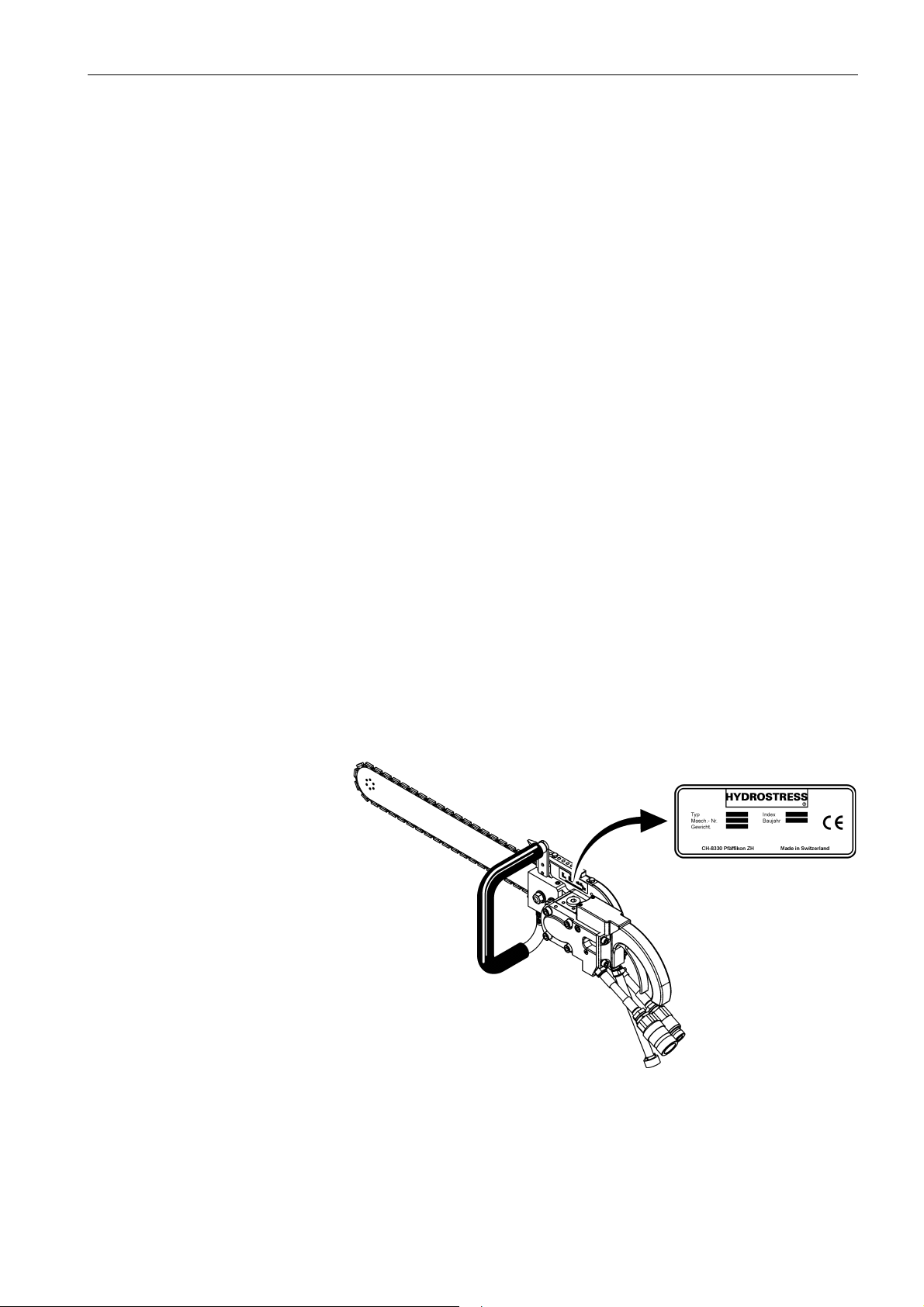
1.1.5 Name plate
Fig. 1-2 Name plate
HCH5011 / 001 1-3
Page 10
Product description Operating instructions
1.2 Technical data
1.2.1 Chain saw HCH5011
• Can be used with any hydraulic actuator (use a flow divider with
pressure limiter >40 l/min or >140bar)
• Flush cutting possible without removing the protective cover
1.2.1.1 Hydraulic system
Maximum pressure 140 bar
Maximum flow 45 l/min.
Hydraulic hose Length 2 m
1.2.1.2 Water
Minimum working pressure 2.5 bar
Minimum flow 7.5 l/min.
1.2.1.3 Weight
Chain saw HCH5011 incl. bar and chain 10.5 kg
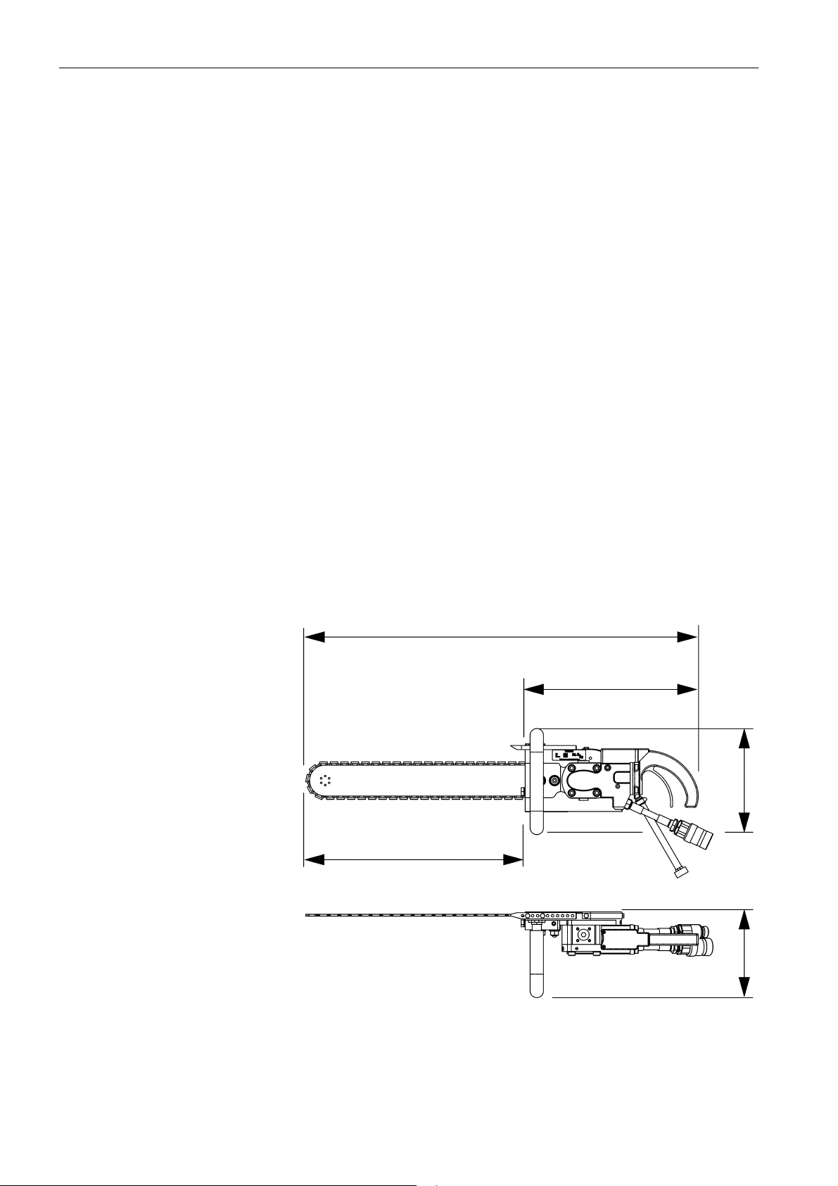
1.2.1.4 Dimensions Chain saw HCH5011
975 mm
560 mm
415 mm
265 mm
230 mm
Fig. 1-3 Dimensions Chain saw HCH5011
1-4 HCH5011 / 001
Page 11

Operating instructions Product description
1.2.2 Noise level
Depending on the working environment, the Chain saw HCH5011 can
cause excessive noise during operation.
The noise can permanently harm the hearing of operating personnel and
of other people nearby within a short time .
Ear protectors must therefore always be worn while working.
Danger
Noise danger
When using the Chain saw HCH5011 hearing protection must be
worn.
If this instruction is not followed irreparable hearing damage may
result.
1.2.3 TYROLIT Hydrostress AG- Bar
1.2.3.1 Bar 20“ (Chain saw HCH5011)
Length / Cutting depth 20“ (approx. 50 cm) / 42 cm
Width 85 mm
1.2.3.2 Bar 16“
Length / Cutting depth 16“ (approx. 40 cm) / 32 cm
Width 85 mm
(75 mm without chain)
(75 mm without chain)
HCH5011 / 001 1-5
Page 12

Product description Operating instructions
1.2.4 Diamond chains
The Chain saw HCH5011 is fitted as standard with the Hydrostress
Universal O-Ring diamond chain 20“ with double pump er .
1.2.4.1 Hydrostress Universal O-Ring diamond chain with double pumper
Application:
– Concrete with a moderate degree of reinforcement (reinforcing irons
of up to dia. 12mm)
– Brick and limestone
– Hard and soft natural stone
Hydrostress Universal O-Ring diamond chain 20“ with double
pumper
Part No. 10978001
Type Diamond chain with double
pumper
Number of segments 43
Segment dimensions:
Height 5.8 mm
Width 5.7 mm
Length 14 mm
Diamond segments laser-welded
Cutting speed 24 m/s
Hydrostress Universal O-Ring diamond chain 16“ with double
pumper
Part No. 10978132
Type Diamond chain with double
pumper
Number of segments 37
Segment dimensions:
Height 5.8 mm
Width 5.7 mm
Length 14 mm
Diamond segments laser-welded
Cutting speed 24 m/s
1-6 HCH5011 / 001
Page 13

Operating instructions Product description
1.2.4.2 Hydrostress concrete O-Ring diamond chains
The Hydrostress “concrete O-ring diamond chain” is characterised by a
long service life and high cutting power in highly reinforced concrete.
Application:
– Concrete with a high degr ee o f re infor ceme nt (r einfo rcing irons o f up
to dia. 19mm)
– Brick and limestone
– Hard natural stone
Hydrostress Concrete O-Ring diamond chain 20“
Part No. 10977642
Number of segments 43
Segment dimensions:
Height 5.8 mm
Width 5.7 mm
Length 15.2 mm
Diamond segments laser-welded
Cutting speed 24 m/s
Hydrostress Concrete O-Ring diamond chain 16“
Part No. 10978131
Number of segments 37
Segment dimensions:
Height 5.8 mm
Width 5.7 mm
Length 15.2 mm
Diamond segments laser-welded
Cutting speed 24 m/s
HCH5011 / 001 1-7
Page 14
Product description Operating instructions
1.3 Accessories
• Flow divider / Pressure limiter 40 l/min, 140 bar
• Pressure control valve 140 bar
1.4 Scope of supply
Complete chain saw system HCH5011:
• Chain saw HCH5011
• Carrying case HCH5011
• Tool kit HCH5011
• Operating Instructions / Spare parts list
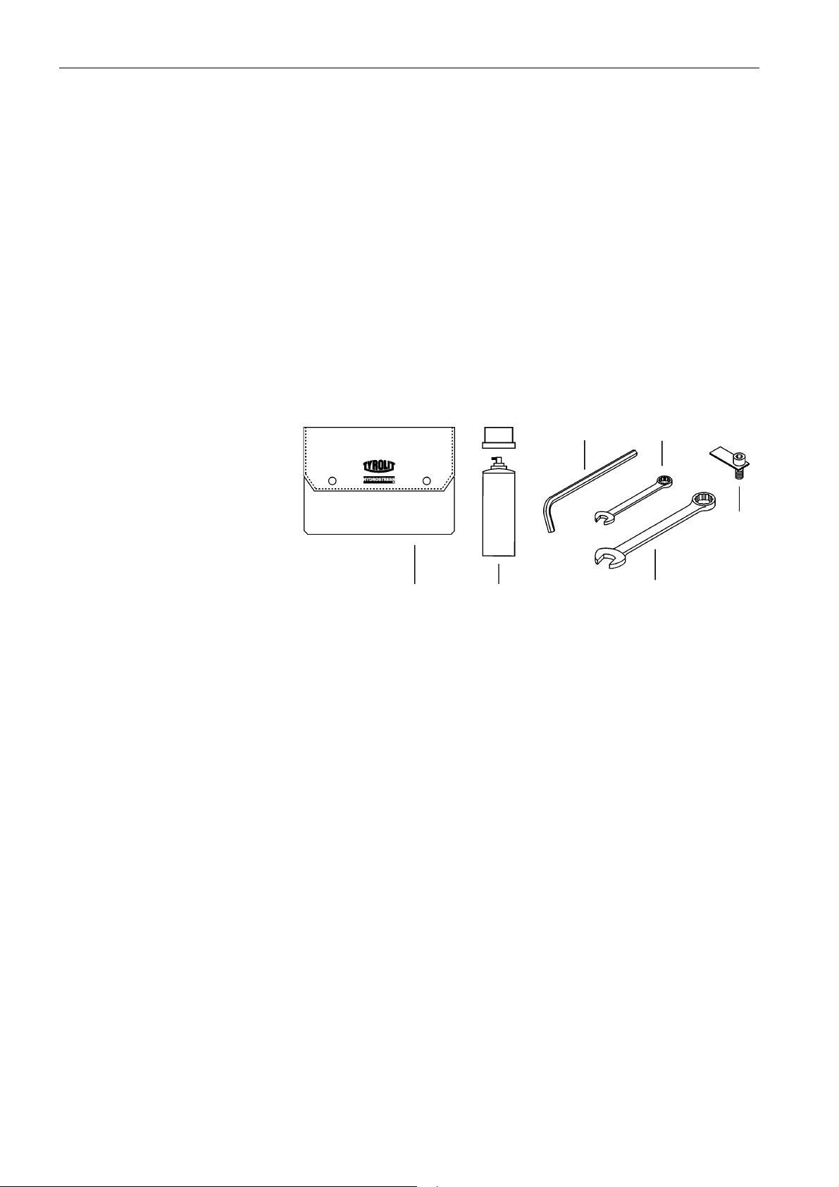
1.4.1 Tool kit comprises:
Fig. 1-4 Tool kit
1. Plastic tool bag Part No. 976497
2. Chain spray Part No. 975061
3. Allen key SW 5 Part No. 973791
4. Ring/open ended spanner SW 10 Part No. 973781
5. Ring/open ended spanner SW 19 Part No. 973784
6. Drive wheel assembly guide Part No. 962724
3
4
6
1
2
5
1-8 HCH5011 / 001
Page 15

Operating instructions Safety instructions
2 Safety instructions
2.1 General
2.1.1 Target audience
This chapter describes the safety instructions that it is essential to follow
when using the Chain saw HCH5011.
All persons who work on and with the Chain saw HCH5011, have a duty
to read and understand the chapters of the Operating instructions relevant
to their particular activities.
This applies in particular to the “Safety instructions” chapter which is
mandatory for all persons and activities.
2.1.2 Observance of the safety instructions
No work must be performed on or with the Chain saw HCH5011 before the
safety instructions contained in the Operating instructions (Chap ter 2) have
been read and understood. The Operating instructions are mandatory for
all work – abridged instructions should only be used in the form of
checklists.
The Chain saw HCH5011 has been inspected before being shipped and
is delivered in perfect condition. TYROLIT Hydrostress AG does not
accept any liability for damage caused by the failure to observe the
instructions and information provided in the Operating instructions. This
applies in particular to:
• Damage caused by improper use and operator error.
• Damage caused by failure to observe safety-related information in the
Operating instructions or shown on the warning signs fitted to the
machine.
• Damage caused by defective or absence of maintenance work.
Independently performed conversions and alterations may affect safety
and are not permitted.
2.1.3 Use for intended application
The intended application is described in “Chapter 1” under 1.1.2, 1-2.
2.1.4 Observance of the information on workplace safety and
danger area
The workplace and danger area are described in “Chapter 1” under
1.1.3, 1-2.
HCH5011 / 001 2-1
Page 16

Safety instructions Operating instructions
2.2 Safety principles
2.2.1 Delimitation of the safety concept
The Chain saw HCH5011 has no effect on the safety concept of the
connected systems, apparatus and installations.
2.2.2 Safety elements
Protection from personal injury is based primarily on a safety concept and
design safety.
2.2.2.1 Passive safety elements
Protection from live parts
All functional units that contain parts which ca rry hazardous voltag es, are
shock-protected by suitable covers.
2.2.3 Removing protective devices
Protective devices should only be removed when the device is turned off,
disconnected from the mains and at a standstill. Safety components in
particular should only be removed and refitted by authorised personnel,
see “Chapter 2”2.6.1, 2-7.
Before using the Chain saw HCH5011 again, the safety elements must be
checked for correct operation.
2.2.4 Safety measures (organisational)
2.2.4.1 Product monitoring obligation
Operating personnel must notify changes in the operational behaviour or
safety-related components to a responsible person or the manufacturer
immediately.
2.2.4.2 Location of Operating instructions
A copy of theOperating instructions must be available at all times to staff at
the place of use of the apparatus.
2-2 HCH5011 / 001
Page 17

Operating instructions Safety instructions
2.3 General safety rules
2.3.1 Statutory provisions
The generally applicable national and local safety and accident preven tion
provisions and the supplementary operator regulations must be followed
and complied with.
2.3.2 I nspection and maintenance obligation
The operator is under an obligation to only use the Chain saw HCH5011
when it is in a perfect and undamaged condition. The maintenance
intervals shown in the Operating instructions must be adhered to without
fail. Malfunctions and mechanical damage must be rectified without delay.
2.3.3 S pare parts
Only TYROLIT Hydrostress AG original spare parts should be used.
Otherwise damage may be caused to the Chain saw HCH5011 or to other
property and persons.
2.3.4 P ower connections
The Chain saw HCH5011 must be connected and co upled to the drive
assembly used in accordance with the Operating instructions.
2.3.5 Modifications
No technical alterations should be made to the apparatus in the form of
additions or conversions without the written consent of TYROLIT
Hydrostress AG.
2.3.6 Safety instructions in the individual chapters
The chapters of these Operating instructions contain additional safety
instructions. These make reference to specific potential dangers (residual
dangers). The instructions must be followed closely and require that the
actions described are taken.
HCH5011 / 001 2-3
Page 18
Safety instructions Operating instructions
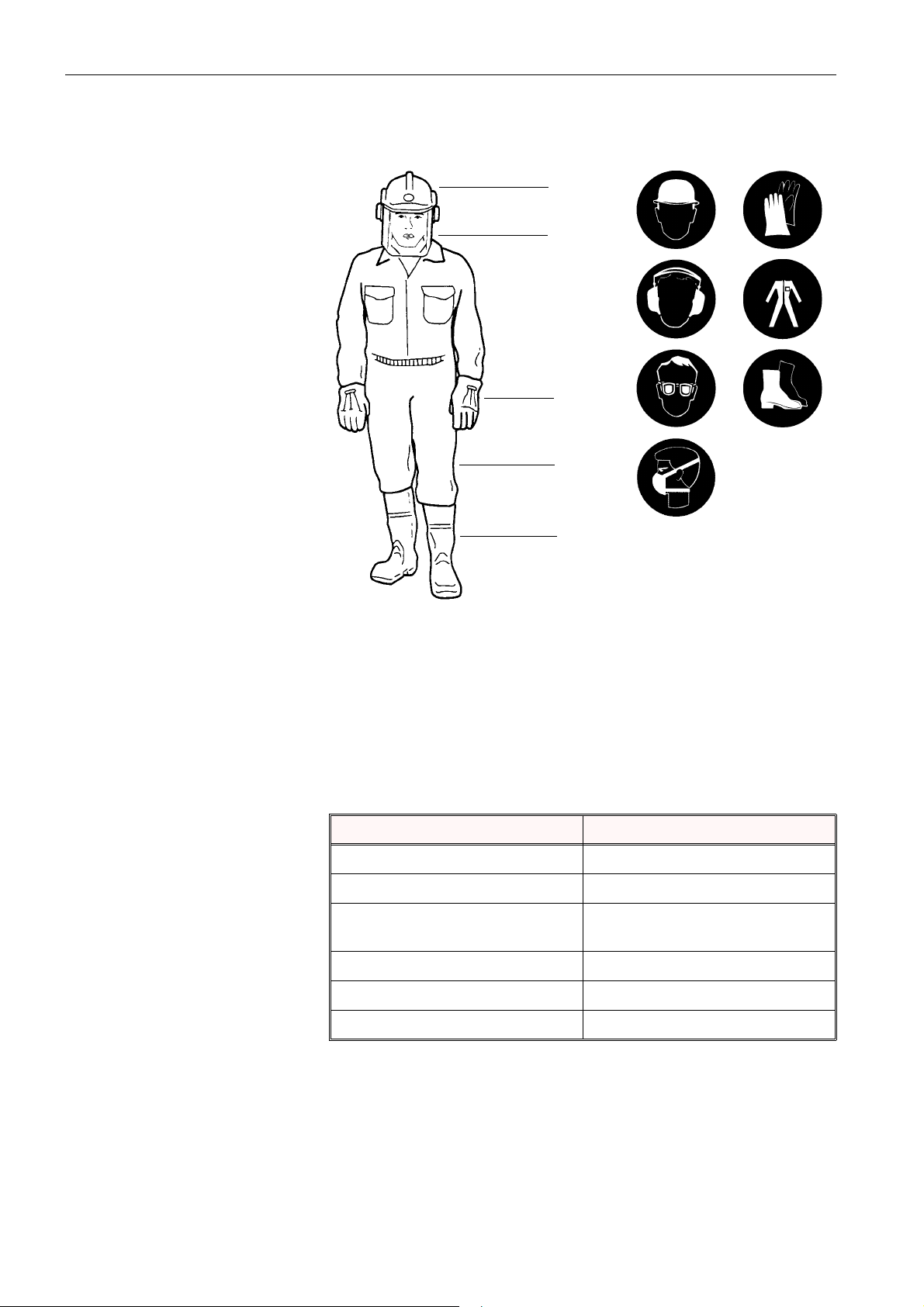
2.3.7 Safety clothing
1
2 / 3
4
5
6
Fig. 2-1 Safety clothing
1. Helmet with ear protectors 5. Waterproof, sturdy,
2. Visor or goggles comfortable clothing
3. Breathing mask 6. Work boots with steel toecaps
4. Waterproof gloves and non-slip soles
Safety clothing must always be worn when drilling, sawing, nibbling or
compressing concrete or stone in order to protect against the following
dangers:
Sources of danger Safety clothing
Falling parts: Helmet, steel-capped safety shoes
Moving, sharp-edged parts: Safety gloves
Flying pieces of concrete and
stone, flying sparks:
Slipping: Anti-slip shoes
Goggle or helmet with visor
Noise Ear protectors
Contamination of respiratory tracts Respiratory mask
2-4 HCH5011 / 001
Page 19
Operating instructions Safety instructions
2.4 Information and symbols
In these Operating instructions information panels are used to draw
attention to residual dangers and to point out important technical
requirements.
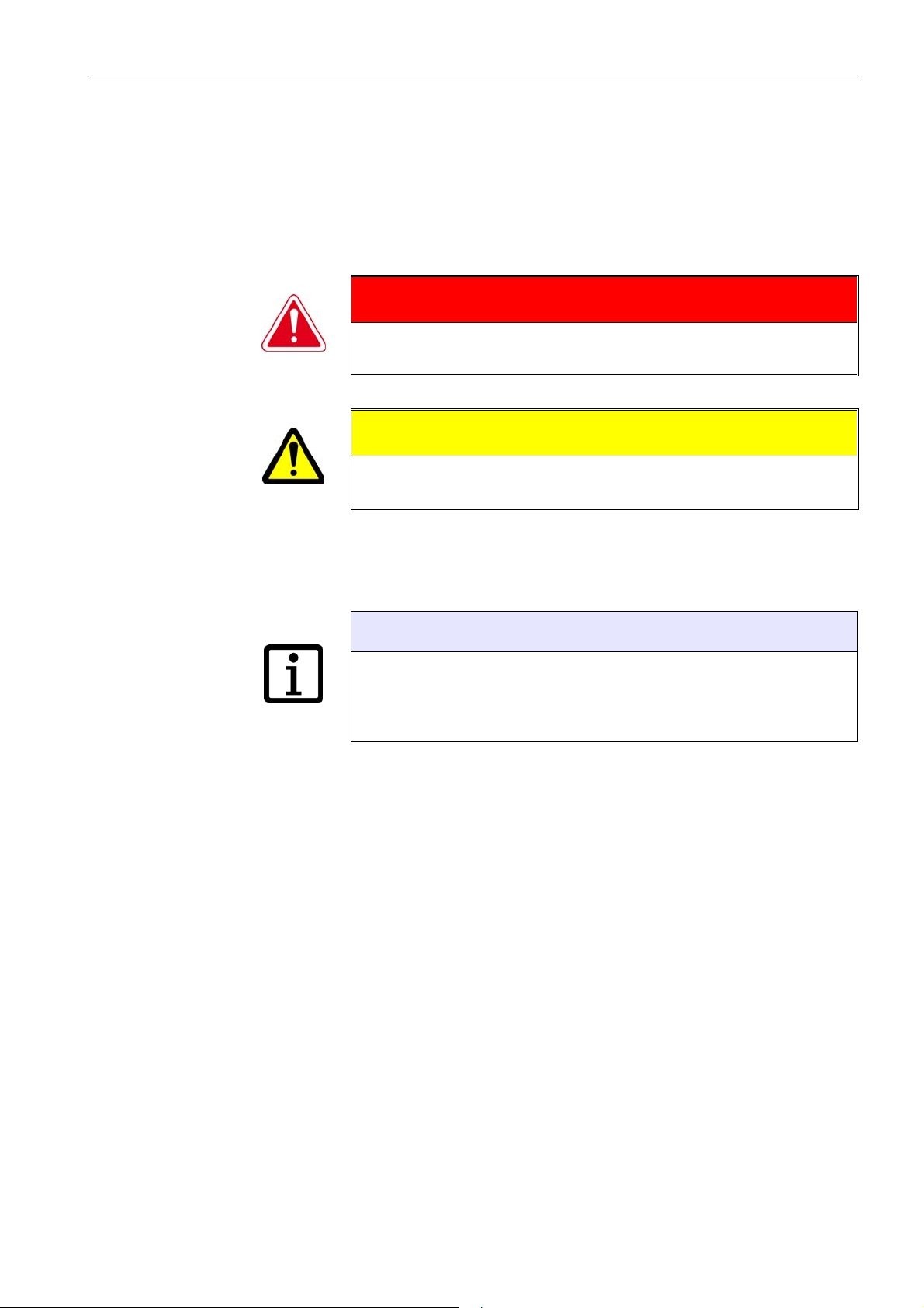
2.4.1 Danger symbols in the Operating instructions
Danger
Warning of danger, where failure to comply could lead to death or
serious injury.
Warning
Warning of danger, where failure to comply could lead to injury or
damage to property.
Fig. 2-2 Danger and warning notices
2.4.2 Information symbol
Text displayed in this way is practical information and is aimed at
achieving optimum use of the installation or appa rat us . Fa ilu re to tak e
note of this information may mean that the performances shown in the
technical data can no longer be guaranteed.
Fig. 2-3 Information notice
Information
HCH5011 / 001 2-5
Page 20

Safety instructions Operating instructions
2.5 Generally applicable warnings of residual
dangers
In the following warnings of residual dangers are shown that are generally
applicable to all work (with and on the saw systems and during all phases
of the life of the systems).
Danger
Electric shock due to defective electronic equipment.
The electrotechnical equipment must be checked prior to each use
and from time to time during prolonged usage. Defective parts
such as cables and plugs must be exchanged by electrotechnically
trained personnel in the powered down state.
Failure to comply with this regulation may lead to serious physical
injury or death. Secondary damage such as fires may also occur.
Warning
Danger from sharp tool edges.
Touching a tool whilst it is still in motion is prohibited.
When touching tools at a standstill it is recommended that
protective gloves are worn.
Failure to adhere to this regulation may result in cut wounds to the
hands.
Warning
Danger of allergic reactions if skin comes into contact with
hydraulic oil.
Persons who have an allergic reaction to hydraulic oil must wear
protective gloves and goggles when carrying out work where th ey
come into contact with hydraulic oil. Any areas of the skin affected
must be rinsed immediately with copious amounts of water.
Failure to adhere to this regulation may result in allergic reactions
or injuries to the eyes.
2-6 HCH5011 / 001
Page 21

Operating instructions Safety instructions
2.6 Responsibility
2.6.1 Authorised personnel
Work on or with TYROLIT Hydrostress AG machines or systems should
only be performed by authorised personnel. Personnel are considered by
TYROLIT Hydrostress AG to be authorised if they meet the necessary
training and know-how requirements and they have been assigned a
precise functional role.
The personnel qualifications for the corresponding work are contained in
the introduction under “General” of the respective chapters.
2.6.2 The manufacturer
TYROLIT Hydrostress AG or a company expressly nominated by
TYROLIT Hydrostress AG is deemed to be the manufacturer of the
products supplied by TYROLIT Hydrostress AG. Within the context of an
integrated quality and safety control system the manufacturer is entitled to
request from the operator information on the products.
2.6.3 Operator
The operator named by TYROLIT Hydrostress AG is the primary, legal
entity responsible for the correct use of the product and for the training and
use of the authorised personnel. The operator sets out the mandatory skills
and level of training of the authorised personnel for his company.
2.6.4 Operative (user)
User is the term employed by TYROLIT Hydrostress AG to designate a
person who independently performs the following work:
•Sets up TYROLIT Hydrostress AG machines or systems for tasks
according to the intended purpose.
• Performs tasks independently and monitors these.
• Locates malfunctions and initiates or performs troubleshooting.
• Carries out servicing and simple maintenance.
• Observes the correction functioning of the safety devices.
2.6.5 Service engineers
Service engineer is a term used by TYROLIT Hydrostress AG to
designate a person who independently performs the following work:
• Installs TYROLIT Hydrostress AG machines and systems and controls
their correct application.
• Makes adjustments to machines and system for which special access
rights are required.
• Performs repairs, complex service work and corrective work.
HCH5011 / 001 2-7
Page 22

Safety instructions Operating instructions
2.6.6 Qualification and training
2.6.6.1 Operator
• A technical trained person in a specialist role.
• Has extensive experience in personnel training and danger assessment.
• Has read and understood the “Safety instructions” chapter.
2.6.6.2 User
• Has completed concrete expert training or has professional experien ce.
• Has received an introduction (basic training) to operation of the
Chain saw HCH5011 from a service engineer.
• Has read and understood chapter 2 “Safety instructions”.
2.6.6.3 Service engineers
• Specialist professional training (mechanical / electrotechnical).
• Has attended specialist courses at TYROLIT Hydrostress AG.
• Has read and understood the “Safety instructions” chapter.
2-8 HCH5011 / 001
Page 23

Operating instructions Design and function
3 Design and function
3.1 Design
The Chain saw HCH5011 is comprised the following components.
• Chain saw unit
• TYROLIT Hydrostress AG bar
• TYROLIT Hydrostress AG diamond chain
Safety component:
• Chain guard
Fig. 3-1 Chain saw HCH5011 design
1. Chain saw unit
2. Bar
3. Diamond chain
4. Chain guard
3.2 Function
The overall function of the Chain saw HCH5011 remains exactly the same.
The Chain saw HCH5011 is powered by a hydraulic drive ass embly. The
chain is driven by the hydraulic motor incorporated into the chai n saw unit.
The driven chain is inserted into the material to be cut.
1
4
2
3
HCH5011 / 001 3-1
Page 24

Design and function Operating instructions
3.3 Component description
3.3.1 Chain saw unit
3.3.1.1 Design
4
1
2
6
3
5
Fig. 3-2 Chain saw unit
3.3.1.2 Function
The chain saw unit is the ce ntra l com pon ent of t he Chain saw HCH5011.
The chain saw unit incorporates the drive motor and the operating handle
and T-handle for using the HCH5011. The unit along with its valve block
and the hydraulic and water connections also constitutes the interface with
the power source (drive assembly).
8
10
9
11
7
1. Operating handle with manual starter 7. Water connection
2. Water level housing 8. Name plate
3. Drive wheel 9. Valve block
4. Fitting aid (chain-engraving) 10.Chain guard
5. Cutting mandrel 11.T-handle
6. Hydraulic connection
3-2 HCH5011 / 001
Page 25

Operating instructions Design and function
3.3.2 TYROLIT Hydrostress AG bar
3.3.2.1 Design
34
Fig. 3-3 Bar
3.3.2.2 Function
The bar is securely fixed to the chain saw unit. The chain runs and is guided
on the bar. The bar provides lateral support for the chain. The cutting
pressure is absorbed via the bar.
1
1. Water inlet 4. Assembly opening
2. Chain guide 5. Reversing wheel
3. Assembly bore hole
for chain tensioner
2
5
Information
The bar serves solely to guide the diamond chain. Never use the bar as
a lifting tool or a crow bar.
HCH5011 / 001 3-3
Page 26

Design and function Operating instructions
3.3.3 Diamond chain
3.3.3.1 Design
The diamond chain has a so-called O-ring design (SE AL- PRO ).
For the chain specification see “Chapter 1” 1.2.4, 1-6
Dimensions of a new chain
5.7mm
5.8 mm
Fig. 3-4 Dimensions of new chain
Dimensions of a worn chain
4.7mm
1.5 mm
Fig. 3-5 Dimensions of worn chain
Danger
When working with a worn chain there is a danger of the chain
breaking.
A worn chain must be replaced by a new chain.
Do not take any notice of the fact that some segments are not
completely worn.
Failure to comply with this regulation may lead to serious physical
injury or death.
3-4 HCH5011 / 001
Page 27

Operating instructions Design and function
Direction of travel and position of diamond chain
Ensure the correct position and direction of travel when fitting a chain.
The engraved mark on the chain saw unit is intended as a fitting aid.
1
2
Fig. 3-6 Diamond chain position and direction of travel
1. Fitting aid (engraving)
2. Chain direction of travel
Working with an incorrectly fitted chain will reduce the lifetime of
the chain and there is a danger of the chain breaking.
Insert the chain correctly according to the engraved mark.
Failure to comply with this regulation may lead to serious physical
injury or death.
3.3.3.2 Function
The diamond chain constitutes the tool for the Chain saw HCH5011. It is
with the help of the chain that the cut is performed.
Danger
HCH5011 / 001 3-5
Page 28

Design and function Operating instructions
3-6 HCH5011 / 001
Page 29

Operating instructions Controls and displays
4 Controls and displays
1
2
3
Fig. 4-1 Controls
1. Water level housing 4. Operating handle with manual starter
2. Locking cut-out 5. Couplings
3. T handle
4.1 Controls
Locking cut-out
Pressing the locking cut-out enables the ON/OFF function. This cut-out
ensures secure locking of the Chain saw HCH5011.
T handle
The T handle is used to hold and carry the Chain saw HCH5011.
Operating handle with manual starter
The operating handle with manual starter is secured by the locking cut-out
against unintentional activation. This must be operated before the Chain
saw HCH5011 can be switched on.
Couplings
4
5
The Chain saw HCH5011 is connected to the power source (power unit)
via the couplings.
4.2 Displays
Water level housing
The water level housing contains three bubble levels for alignment and
control of the direction of cut.
HCH5011 / 001 4-1
Page 30

Controls and displays Operating instructions
4-2 HCH5011 / 001
Page 31

Operating instructions Putting into operation
5 Putting into operation
The Chain saw HCH5011 is supplied ready for use. The information
provided in “Chapter 6”, Operation, also applies to the putting into
operation of your apparatus.
HCH5011 / 001 5-1
Page 32

Putting into operation Operating instructions
5-2 HCH5011 / 001
Page 33

Operating instructions Operation
6 Operation
6.1 General
Before proceeding read Chapter 2 «Safety instructions», 2-1 in these
Operating instructions. Be sure also to take note of all the danger
information given here and follow the instructions on how to avoid physical
injury and damage to property.
6.1.1 S afety instructions
It is essential to observe the following safety instructions, in particular in
relation to the operation of the HCH5011.
Danger
Danger of falling heavy parts.
When performing the types of work described in this chapter, it is
essential to wear the following individual protective equipment:
helmet, goggles, protective gloves and safety shoes. (s ee “Chapter
2” 2.3.7, 2-4)
It is essential that the work instructions and proc edures described
in this safety manual are followed.
Failure to observe this regulation may lead to serious physical
injury, and possibly even death, and to property damage.
Danger
Danger from machine suddenly starting up.
Before switching on the Chain saw HCH5011 the operator must
ensure that no other person is present in the danger areas.
Failure to adhere to this regulation may result in cut wounds to
body parts and damage to property.
Danger
When working with a worn chain there is a danger of the chain
breaking.
Worn chains must be replaced with new ones.
Failure to comply with this regulation may lead to serious physical
injury or death.
HCH5011 / 001 6-1
Page 34

Operation Operating instructions
Danger
Working with an incorrectly fitted chain will reduce the lifetime of
the chain and there is a danger of the chain breaking.
Use the fitting aid (chain engraving) to correctly insert the chain.
Failure to comply with this regulation may lead to serious physical
injury or death.
Danger
Noise danger
When using the Chain saw HCH5011 hearing protection must be
worn.
If this instruction is not followed irreparable hearing damage may
result.
Danger
Danger from uncontrolled movements
When the Chain saw HCH5011 is switche d on , alwa y s ho ld it wi th
both hands using the handles. Thumb s and fingers must be closed
around the handles. Otherwise you may loose control o f the Chain
saw HCH5011. Handles must always be clean and dry.
Failure to observe this regulation may lead to serious physical
injury, and possibly even death, and to property damage.
Danger
Danger from working at excessive chain speed or wit h insufficient
water feed.
This can lead to excessive wear of the chain, which in turn can
result in loss of stability and the chain breaking.
Operate the Chain saw HCH5011 at the correct speed and with
sufficient water feed.
Do not exceed a hydraulic flow of 45 l / min and 140 bar. The
working pressure of the water should be a minimum of 2.5 bar and
the flow a minimum of 7.5 l / min.
Failure to observe this regulation may lead to serious physical
injury, and possibly even death, and to property damage.
6-2 HCH5011 / 001
Page 35

Operating instructions Operation
Danger
Danger from segments or stone chips flying off from the tool.
The danger area must be property secured.
Failure to observe this regulation may lead to serious injury to
body parts, and possibly even death.
Danger
Danger of the Chain saw HCH5011 restarting in the event of an
accident
Ensure that you can quickly stop the Chain saw HCH5011 (see
Emergency Stop in the Operating instructions of the drive
assembly you are using).
Failure to observe this regulation may lead to serious physical
injury, and possibly even death, and to property damage.
HCH5011 / 001 6-3
Page 36

Operation Operating instructions
Warning
Warning of slippery floors
The water feed and abrasion can make standing surfaces smooth
and slippery. You should therefore always ensure you have a firm
footing.
Failure to adhere to this regulation may result in slight or serious
physical injury.
Warning
Warning against working when not in a fit state to do so.
Do not use the Chain saw HCH5011 if you are under the influence
of sedatives or alcohol or if you are overtired.
Failure to adhere to this regulation may result in slight or serious
physical injury.
6.1.2 Personnel qualifications
The Chain saw HCH5011 should not be operated by unauthorised
personnel. Personnel are only authorised where they meet the following
requirements.
• Completion of concrete expert training or having professional
experience.
• Receipt of an introduction (basic training) to the operation of the Chain
saw HCH5011 from a service engineer.
• Read and understood chapter 2 “Safety instructions”.
6-4 HCH5011 / 001
Page 37

Operating instructions Operation
6.2 System requirements
In order to use the Chain saw HCH5011 a hydraulic drive assembly is
needed.
Drive assembly power requirements:
Minimum power: Minimum flow 35 l/min.
Max. pressure 140 bar
Maximum power: Maximum flow 45 l/min.
Max. pressure 140 bar
If the basic power of the drive assembly used is higher, a flow divider /
pressure limiter or a pressure relief valve can be use d.
Operation of the individual system components is described in the
corresponding Operating instructions.
1
4
5
Fig. 6-1 Chain saw HCH5011 with drive assembly
1. Chain saw HCH5011 4. Main oil circuit (inlet)
2. Drive assembly 5. Main oil circuit (outlet)
3. Water feed (cooling water)
6.3 Preparatory operations
Always proceed as follows:
• Sort out fundamental conditions
• Securing the site
2
3
• Securing cutouts
• Decide on position and sequence of the cuts
• Perform a visual inspection of the Chain saw HCH 5011
• Connect the Chain saw HCH5011 to the drive assembly
HCH5011 / 001 6-5
Page 38

Operation Operating instructions
6.3.1 Sort out fundamental conditions
• Determine the position of pipes and cables in walls, floors and ceilings.
• Where does the cooling water used for sawing flow to? (Think about
water damage to the electrical supply).
6.3.2 Securing the site
• See “Chapter 1” Workplace an d da n ge r ar ea s 1. 1.3, 1-2
6.3.3 Securing cutouts
Secure cutouts from walls and especially from ceilings and floors by
suitable means, e.g. crane, supports, etc.
Check the weight of concrete. (1m³ = 2400-2700 kg)
6.3.4 Decide on position and sequence of the cuts
6.3.4.1 Position of cuts
Find out about the concrete or masonry to be sawed:
– Where does the reinforcement run?
– Is the concrete heavily or lightly reinforced?
Cut across the reinforcement if possible .
6.3.4.2 Cutting sequence
Decide on the sequence of cuts before starting work. For example, for a
window cutout carry out the bottom cut first, then the side cuts, and finally
the top cut.
4
2
3
1
Fig. 6-2 Sequence of cuts for a window cutout
Information
The wrong sequence of cuts can lead to jamming of the bar or damage
to the chain.
6-6 HCH5011 / 001
Page 39

Operating instructions Operation
6.3.5 Perform a visual inspection of the Chain saw HCH5011
6.3.5.1 Check the chain tension
6 mm
Fig. 6-3 Chain tension
– The chain tension is correctly set if with a moderate pull the chain can
be pulled away from the bar by a maximum of 6 mm.
– It must be possible to turn the chain one full rotation with ease by
hand.
For chain tensioning see “Chapter 7”
6.3.5.2 Check the diamond chain for wear
If chain is worn see “Chapter 3” 3.3.3, 3-4
To replace the chain see “Chapter 7”
6.3.5.3 Check the bar for wear
• The bar has been designed so that both sides can be used for working.
Rotate the bar if one side is worn.
Fig. 6-4 Rotating the bar
HCH5011 / 001 6-7
Page 40

Operation Operating instructions
6.3.5.4 Check the reversing wheel on the bar for wear
0
0.8 mm
Fig. 6-5 Worn reversing wheel
When the reversing wheel is in the new condition the distance between the
chain and bar edge is 0.8 mm. If the chain is running on the bar edge, the
reversing wheel must be changed.
Repairs to be performed by an authorised TYROLIT Hydrostress AG
service centre.
6.3.6 Connecting the Chain saw HCH5011
6.3.6.1 Connecting the hoses
Warning
Danger from uncontrolled movements of the HCH5011!
Never connect or disconnect hoses when the unit is running.
Failure to adhere to this regulation may result in cut wounds or
injury to body parts and damage to property.
Warning
Danger from uncontrolled escaping of oil.
Never connect or disconnect hoses when the unit is running.
Failure to adhere to this regulation may result in cut wounds or
injury to body parts and damage to property.
6-8 HCH5011 / 001
Page 41

Operating instructions Operation
6.3.6.2 Hose connections
Before connecting check couplings, Chain saw HCH5011 and feed lines
for cleanliness.
The following hose connections must be established:
1
3
5
Fig. 6-6 Hose connections
Hoses Chain saw HCH5011 Drive assembly hoses
Water inlet (1)
(Coupling – male connector)
Return (3)
(Coupling – male connector)
Flow (5)
(Coupling – female connector)
2
4
6
Water outlet (2)
(Coupling – female connector)
Main circuit oil return (4)
(Coupling – female connector)
Main circuit oil flow (6)
(Coupling – male connector)
Proceed as follows:
• Visual inspection
Check:
– Oil leaks from hoses and couplings
– Couplings for damage and contamination
– Hoses for damage
• Push the hose coupling onto its counterpart until you hear it "click"
• Twist the locking ring of the coupling
Information
If the hoses cannot be connected or this cannot be done easily, they are
under pressure. Depressurise the hoses by means of the pressure relief.
Never use force couplings to connect.
HCH5011 / 001 6-9
Page 42

Operation Operating instructions
6.4 Working with the Chain saw HCH5011
Following the preparatory operations, see “Chapter 6” 6.3, 6-5 the Chain
saw HCH5011 is ready for use.
6.4.1 Areas of use
The Chain saw HCH5011 is suited to the following cutting work:
• Small cutouts / cutting throughs
• Flush cuttings
• Narrow corner cuts
• Irregular shaped cuts
6.4.2 Starting the Chain saw HCH5011
Always proceed as follows:
• Start the drive assembly (see Operating instru ctions for the drive you are
using).
• Open the water valve on the drive assembly and check the water outlet
on the Chain saw HCH5011.
The water outlet on the Chain saw HCH5011 is released by pressing the
locking cut-out and the manual starter.
• Set the required operating pressure.
– Maximum flow 45 l/min.
– Max. pressure 140 bar
• Hold the Chain saw HCH5011 securely with both hands
• Press the locking cut-out and operate the manual starter
• Check the direction of travel of the chain (if this direction of travel of the
chain is wrong, connect the Chain saw HCH5011 properly).
• Perform the desired cut
6.4.3 Cutting sequence
Begin the cutting work taking into account the instructions of “Chapter 6”,
Position and sequence of cuts 6.3.4, 6-6.
Information
6-10 HCH5011 / 001
Page 43

Operating instructions Operation
6.4.4 Working with cutting mandrel
The cutting mandrel (1) has been developed as a mechanical aid that can
be used for horizontal and vertical cuts.
1
Fig. 6-7 Cutting mandrel
HCH5011 / 001 6-11
Page 44

Operation Operating instructions
6.5 After the work
Proceed as follows:
• Close off and decouple the water feed
• Blow out water from all lines
• Remove plug from mains (drive assembly)
• Uncouple hydraulic hoses
• Clean the Chain saw HCH5011 with water
• Lubricate the chain and the bar
6.5.1 Chain and bar lubrication
Fig. 6-8 Chain and bar lubrication
Proceed as follows:
• After final use rinse chain and bar with water. Allow chain to run for 5
seconds without water
• Disconnect the Chain saw HCH5011 from the drive assembly
• Lubricate the chain and bar (chain spray)
• Store the Chain saw HCH5011 in the dry state
Information
Frequent lubrication will extend the life of the diamond chain and the bar.
Information
In order to avoid frost damage, if there is a da nger of fro st once wo rk is
complete or prior to extended breaks in work the entire water system
must be emptied and blown out.
6-12 HCH5011 / 001
Page 45

Operating instructions Maintenance
7 Maintenance
7.1 General
Before proceeding read Chapter 2 «Safety instructions», 2-1 in these
Operating instructions. Be sure also to take note of all the danger
information given here and follow the instructions on how to avoid physical
injury and damage to property.
7.1.1 S afety instructions
It is essential to observe the following safety instructions, in particular in
relation to the maintenance of the HCH5011.
Danger
Danger of falling heavy parts.
When performing the types of work described in this chapter, it is
essential to wear the following individual protective equipment:
helmet, goggles, protective gloves and safety shoes (see “Chapter
2” 2.3.7, 2-4).
It is essential that the work instructions and proc edures described
in this safety manual are followed.
Failure to observe this regulation may lead to serious physical
injury, and possibly even death, and to property damage.
Danger
Danger from segments flying off from the tool.
In no event should diamond chains have new segments fitted by
unauthorised operators.
Failure to observe this regulation may lead to serious physical
injury, and possibly even death, and to property damage.
Warning
Danger from uncontrolled movements of the HCH5011!
Never connect or disconnect hoses when the unit is running.
Failure to adhere to this regulation may result in cut wounds or
injury to body parts and damage to property.
HCH5011 / 001 7-1
Page 46

Maintenance Operating instructions
Warning
Danger from uncontrolled escaping of oil.
Never connect or disconnect hoses when the unit is running.
Failure to adhere to this regulation may result in cut wounds or
injury to body parts and damage to property.
7.1.2 Personnel qualifications
The Chain saw HCH5011 should not be maintained by unauthorised
persons. Personnel are only authorised where they meet the following
requirements.
• Have completed concrete expert training or professional experience.
• Have received an introduction (basic training) to the operation of the
Chain saw HCH5011 from a service engineer.
• Have read and understood chapter 2 “Safety instructions”.
7-2 HCH5011 / 001
Page 47

Operating instructions Maintenance
7.2 Maintenance and servicing table
The following maintenance work must be performed according to the
prescribed cycles. Wear parts that are not subject to particular
maintenance intervals should also be checked regularly for wear and
adjusted or exchanged as necessary.
Maintain the system within the indicated intervals in order to ensure:
• Safety for the operator
• Optimum performance
• Optimum reliability at all times
before each
start-up
Hydraulic system Hydraulic hose inspection
(Tightness / cleanliness)
Coupling inspection
(Tightness / cleanliness)
Water economy Water line
(Tightness / cleanliness)
Blow out water (frost hazard) X
Chain saw unit Tightness / cleanliness X X
Retighten accessible screws and nuts X X
Bar Water cleaning X
Lubrication X X
Check for wear X X X X
Diamond chain Water cleaning X
Lubrication X X
Chain tension X
Check for wear X X X X
XX XX
XX XX
XX XX
upon completion of work
weekly
annually
in the event of malfunction
in the event of damage
Major service May only be carried out by TYROLIT
Hydrostress AG or an authorized
representative
HCH5011 / 001 7-3
X
Page 48

Maintenance Operating instructions
Information
Wear in the drive and reversing wheel / di amond chain and bar is highly
dependent upon the thickness, condition and degree of reinforcement of
the concrete being worked.
Information
In order to achieve an optimum balance between the diamond chain a nd
the drive wheel, whenever the chain is exchanged due to wear the drive
wheel should also be replaced.
Information
In order to achieve an optimum balance between the diamond chain a nd
the bar, every other time the chain is exchanged due to wear the bar
should also be replaced.
7-4 HCH5011 / 001
Page 49

Operating instructions Servicing
8 Servicing
8.1 General
Before proceeding read Chapter 2 «Safety instructions», 2-1 in these
Operating instructions. Be sure also to take note of all the danger
information given here and follow the instructions on how to avoid physical
injury and damage to property.
8.1.1 S afety instructions
It is essential to observe the following safety instructions, in particular in
relation to the servicing of the HCH5011.
Danger
Danger of falling heavy parts.
When performing the types of work described in this chapter, it is
essential to wear the following individual protective equipment:
helmet, goggles, protective gloves and safety shoes (see “Chapter
2” 2.3.7, 2-4).
It is essential that the work instructions and proc edures described
in this safety manual are followed.
Failure to observe this regulation may lead to serious physical
injury, and possibly even death, and to property damage.
Danger
Danger from segments flying off from the tool.
In no event should diamond chains have new segments fitted by
unauthorised operators.
Failure to observe this regulation may lead to serious physical
injury, and possibly even death, and to property damage.
Warning
Danger from uncontrolled movements of the HCH5011!
Never connect or disconnect hoses when the unit is running.
Failure to adhere to this regulation may result in cut wounds or
injury to body parts and damage to property.
HCH5011 / 001 8-1
Page 50

Servicing Operating instructions
Warning
Danger from uncontrolled escaping of oil.
Never connect or disconnect hoses when the unit is running.
Failure to adhere to this regulation may result in cut wounds or
injury to body parts and damage to property.
8.1.2 Personnel qualifications
The Chain saw HCH5011 should not be serviced by unauthorised
persons. Personnel are only authorised where they meet the following
requirements.
• Have completed concrete expert training or professional experience.
• Have received an introduction (basic training) to the operation of the
Chain saw HCH5011 from a service engineer.
Have read and understood chapter 2 “Safety instructions”.
8-2 HCH5011 / 001
Page 51

Operating instructions Servicing
8.2 Tensioning the diamond chain
2
Fig. 8-1 Tensioning the diamond chain
Proceed as follows:
To tension the diamond chain you will need the fork wrench SW 19
supplied with the tool kit.
• Loosen both nuts (1)
• Adjust the adjusting screw (2) for the correct chain tension
• Tighten both nuts (1)
8.2.1 C orrect chain tension
• The chain tension is correctly set if, in the middle of the bar, with a
moderate pull the chain can be pulled away from the bar by a maximum
of 6 mm.
• It must be possible to turn the chain in the uncoupled state one full
rotation with ease by hand.
1
6 mm
Fig. 8-2 Chain tension
HCH5011 / 001 8-3
Page 52

Servicing Operating instructions
8.3 Changing the diamond chain
To change the diamond chain you will need the fork wrenches SW 19 and
SW 10 supplied with the tool kit.
4
23
3
Fig. 8-3 Changing the diamond chain
3
8.3.1 Removing the diamond chain
Proceed as follows:
• Loosen the three chain guard securing screws (3)
Fork wrench SW10
• Remove the chain guard (4)
• Loosen both nuts (1)
Fork wrench SW19
• Release the tension in the diamond chain via the adjusting screw (2)
Fork wrench SW19
1
• Remove the diamond chain
8.3.2 Fitting the diamond chain
Proceed as follows:
• Place the diamond chain around the drive and reversing wheel and in
the chain guide of the bar. Note the direction of travel and installation
position of the diamond chain. See “Chapter 3” 3.3.3, 3-4
• Tension the diamond chain, see “Chapter 8” 8.2, 8-3
• Tighten both nuts (1)
Fork wrench SW1
• Fit the chain guard (4) with the fixing screws (3)
Fork wrench SW10
8-4 HCH5011 / 001
Page 53

Operating instructions Servicing
8.4 Changing the bar
To change the bar you will need the fork wrenches SW 19 and SW 10
supplied with the tool kit.
4
3
Fig. 8-4 Changing the bar
3
8.4.1 Dismantling the bar
Proceed as follows:
• Loosen the three chain guard securing screws (3)
Fork wrench SW10
• Remove the chain guard (4) and the chain tensioning device (5)
• Loosen both nuts (1)
Fork wrench SW19
• Release the tension in the diamond chain via the adjusting screw (2)
Fork wrench SW19
23
1
5
• Remove the diamond chain
• Remove the nuts (1) from the chain tensioning device (5)
• Remove the bar
8.4.2 Fitting the bar
Proceed as follows:
• Place the bar in the chain saw unit
• Fit the chain tensioning device (5) and tighten nuts (1) slightly
• Place the diamond chain around the drive and reversing wheel and in
the chain guide of the bar. Note the direction of travel and installation
position of the diamond chain. See “Chapter 3” 3.3.3, 3-4
• To tension the diamond chain see 8.2, 8-3
• Tighten both nuts (1) with fork wrench SW19
• Fit the chain guard (4) with the fixing screws (3)
Fork wrench SW10
HCH5011 / 001 8-5
Page 54

Servicing Operating instructions
8.5 Changing the drive wheel
In order to be able to change the drive wheel you must first dismantle the
bar, see “Chapter 8” 8.4.1, 8-5
To change the drive wheel you will need the wheel stop and Allen key SW
5 supplied with the tool kit.
1
Fig. 8-5 Changing the drive wheel
8.5.1 Dismantling the drive wheel
Proceed as follows:
• Fit the drive wheel stop (1)
• Loosen the left-hand thread Allen screw (2)
Allen key SW 5
• Remove the drive wheel and the V-seal
8.5.2 Fitting the drive wheel
• Fit the V-seal (grease the seal)
• Push drive wheel onto drive shaft
• Fit the drive wheel stop (1) and nuts (1)
• Secure the drive wheel with the Allen screw (2)
and Loctite 243
• Remove the drive wheel stop
2
8-6 HCH5011 / 001
Page 55

Operating instructions Servicing
8.6 Troubleshooting
Proceed systematically when looking for the causes of a fault. Refer to the
operating instructions of the drive assembly you are using when doing this.
The following table will help you to narrow down and rectify the source of
the fault.
Fault Possible cause Solution
Chain saw HCH5011 cannot be
started
Diamond chain broken Loose metal or stone in building
Drive assembly is switched off Switch on drive assembly
Emergency stop on drive assembly
has been activated
Chain tension too high Tension diamond chain correctly
Reversing wheel bearing rusted or
reversing wheel worn
Diamond chain has excessive
contact with building structure
Drive wheel incorrectly mounted Check drive wheel
structure
Diamond chain incorrectly
assembled
Diamond chain worn Replace diamond chain
Chain speed is too high Drive assembly power is too high.
Release emergency stop on the
drive assembly
see “Chapter 8” 8.2, 8-3
Free-up bearing with chain spray or
replace reversing wheel
Withdraw from cut and insert into
building structure with chain running
Remove metal or stones or position
cut at another point
Assemble diamond chain correctly
see “Chapter 3” 3.3.3, 3-4
see “Chapter 3” 3.3.3, 3-4
Use a pressure relief valve (140 bar)
or a flow divider (pressure limiter 40
l/min at 140 bar).
Diamond chain seriously worn on
cutting segment
Diamond chain vibrates heavily Diamond chain inadequately
Diamond chain sticks in cut Block being cut out moves Insert stable wood or steel shims in
Diamond chain can no longer be
tensioned, since the chain tensioner
is at its limit
HCH5011 / 001 8-7
Highly reinforced building structure Cannot be removed
Chain speed too low Use hydraulic unit at
min. 35 l/min
Insufficient water Min. pressure 2bar
Tension diamond chain correctly
tensioned
Incorrect cutting sequence Observe cutting sequence
Diamond chain has stretched
through normal wear
see “Chapter 8” 8.2, 8-3
the cut so that the block no longer
moves
see “Chapter 6” 6.3.4, 6-6
Lift bar from tensioning cam A and
tension using tensioning cam B
see “Chapter 8” 8.2, 8-3
Page 56

Servicing Operating instructions
Fault Possible cause Solution
No water coming from the bar and
diamond chain
Water line is blocked Clean water line
Water valve on feed line is closed Open water valve.
Insufficient water pressure Ensure a minimum water pressure
of 7.5 l/min
Diamond chain jumps from bar Chain tension too low Tension diamond chain correctly
see “Chapter 8” 8.2, 8-3
Worn chain guide on bar Replace bar
Worn chain wheels Replace chain wheels
If you are unable to remedy a fault, please call our service centre (see
manufacturer’s address on the reverse of the title page).
To guarantee a rapid and professional solution to the problem, it is
important that you have prepared as follows before calling:
• Try to describe the fault as accurately as possible
• Note the type and index of your unit (name plate)
Fig. 8-6 Name plate
• Have the operating instructions close to hand
8-8 HCH5011 / 001
Page 57

Operating instructions Taking out of service and storage
9 Taking out of service and storage
9.1 Taking out of service
9.2 General
Before proceeding read Chapter 2 «Safety instructions», 2-1 in these
Operating instructions. Be sure also to take note of all the danger
information given here and follow the instructions on how to avoid physical
injury and damage to property.
9.2.1 S afety instructions
It is essential to observe the following safety instructions, in particular in
relation to the taking out of service of the HCH5011.
Danger
Danger of falling heavy parts.
When performing the types of work described in this chapter, it is
essential to wear the following individual protective equipment:
helmet, goggles, protective gloves and safety shoes (see “Chapter
2” 2.3.7, 2-4).
It is essential that the work instructions and proc edures described
in this safety manual are followed.
Failure to observe this regulation may lead to serious physical
injury, and possibly even death, and to property damage.
Warning
Danger from uncontrolled movements of the HCH5011!
Never connect or disconnect hoses when the unit is running.
Failure to adhere to this regulation may result in cut wounds or
injury to body parts and damage to property.
Warning
Danger from uncontrolled escaping of oil.
Never connect or disconnect hoses when the unit is running.
Failure to adhere to this regulation may result in cut wounds or
injury to body parts and damage to property.
HCH5011 / 001 9-1
Page 58

Taking out of service and storage Opera ting inst ru ctio ns
9.2.2 Personnel qualifications
The Chain saw HCH5011 should not be taken out of service by
unauthorised persons. Personnel are only authorised where they meet the
following requirements.
• Have completed concrete expert training or professional experience.
• Have received an introduction (basic training) to the operation of the
Chain saw HCH5011 from a service engineer.
Have read and understood chapter 2 “Safety instructions”.
9.3 Storage
Some components of the Chain saw HCH5011 consist of materials which
may corrode. If unused for lengthy periods, take the following action:
• Blow the water out of the water lines
• Lightly oil the apparatus
• Store in a dry location
9-2 HCH5011 / 001
Page 59

Operating instructions Transport, Packing
10 Transport, Packing
10.1 Transport
The Chain saw HCH5011 is a high-tech apparatus. Protect it against
transport damage:
• Do not place anything on or against the Chain saw HCH5011
• Protect the Chain saw HCH5011 from impacts
• Transport the Chain saw HCH5011 in the carrying case provided for this
purpose
10.2 Packing
The Chain saw HCH5011 is packed in the carrying case included in the
scope of supply.
HCH5011 / 001 10-1
Page 60

Transport, Packing Operating instructions
10-2 HCH5011 / 001
Page 61

Operating instructions Disposal
11 Disposal
11.1 General
The operator can recycle or dispose of the Chain saw HCH5011 himself
provided he observes the statutor y provisions. In order to dismantle the
apparatus correctly and to properly remove the materials some knowled ge
in the area of mechanics and knowledge about differentiation of waste
materials is necessary.
Before proceeding read Chapter 2 «Safety instructions», 2-1 in these
operating instructions. Be sure also to take note of all the danger
information given here and follow the instructions on how to avoid physical
injury and damage to property.
11.1.1 Safety instructions
It is essential to observe the following safety instructions, in particular in
relation to the disposal of the HCH5011.
Danger of falling heavy parts.
When performing the types of work described in this chapter, it is
essential to wear the following individual protective equipment:
helmet, goggles, protective gloves and safety shoes (see “Chapter
2” 2.3.7, 2-4).
It is essential that the work instructions and proc edures described
in this safety manual are followed.
Failure to observe this regulation may lead to serious physical
injury, and possibly even death, and to property damage.
11.1.2 Personnel qualifications
Personnel performing the work described in this chapter must meet the
following conditions:
• Have and understood the safety instr uc tio ns in “Ch a pt er 2”.
• Completed their technical training (mechanical/electrotechnical)
and be in a position to identify the various material groups.
Danger
HCH5011 / 001 11-1
Page 62

Disposal Operating instructions
11.2 Disposal regulations
The normal local and regional rules and guidelines must be obse rved when
disposing of the Chain saw HCH5011.
11.3 Disposal of the Chain saw HCH5011
To allow proper disposal the components of the HCH5011 must be
dismantled. This is performed by the client’s personnel.
The dismantled parts of the apparatus are sorted by material and sent
separately to the appropriate collection points. Ensure that the following
parts in particular are properly disposed of.
The Chain saw HCH5011 consists of the following materials:
Cast aluminium Rolled aluminium products
Bronze Steel
Rubber Rubber / nylon fabric
Synthetic grease
11-2 HCH5011 / 001
 Loading...