

Page 1
DA435HA: 99901219 20100927
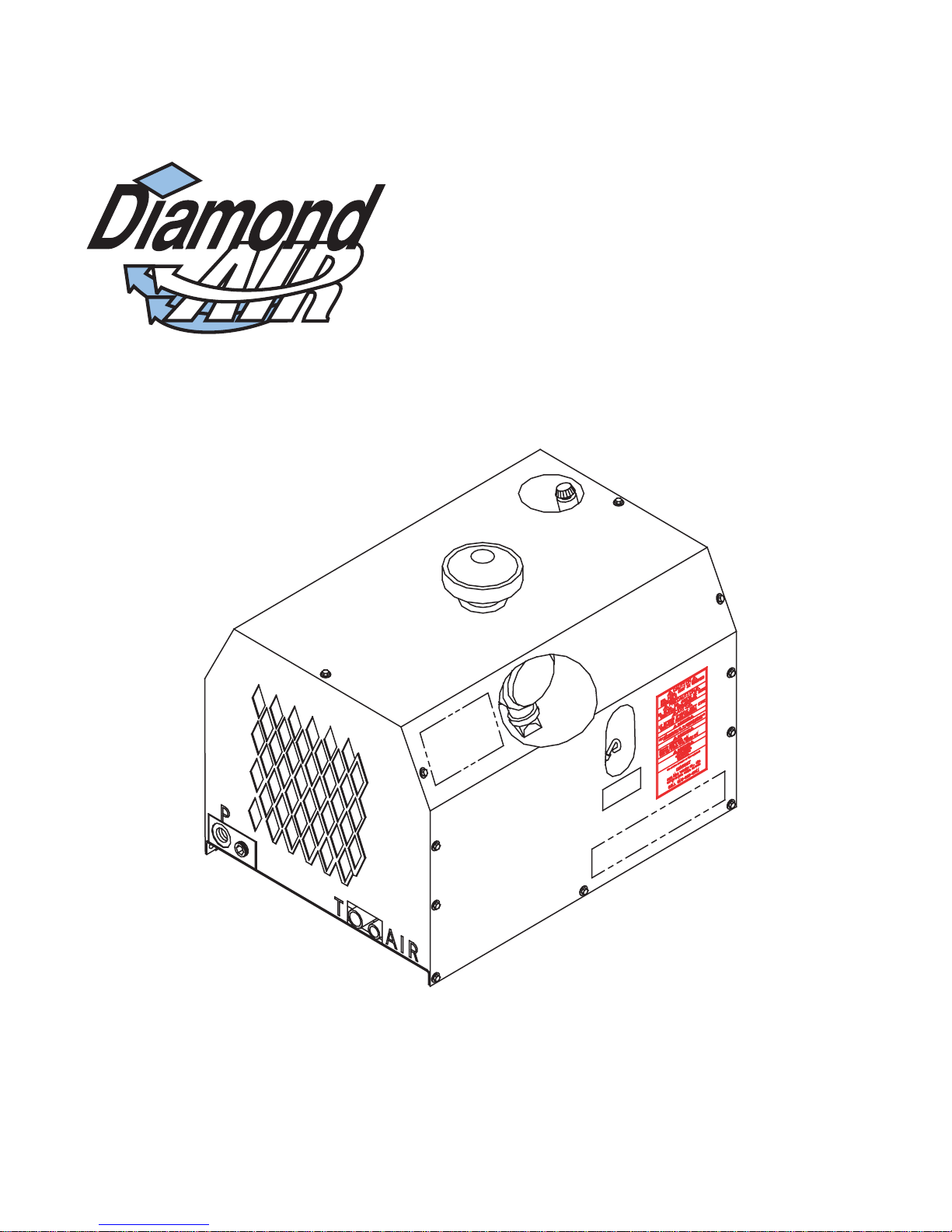
Model DA435HA
Air Compressor
(PART NO. 20013)
(Single Cooler - 10GPM)
(Replaces Model DA435HAR-10)
IOWA MOLD TOOLING CO., INC.
BOX 189, 500 HWY 18 WEST, GARNER, IA 50438
Iowa Mold Tooling Co., Inc. is an Oshkosh Truck Corporation company.
TEL: 641-923-3711
MANUAL PART NUMBER 99901219
Page 2

DA435HA: 99901219: ii
--------
REVISIONS LIST
DATE LOCATION DESCRIPTION OF CHANGE
20000731 4-10 I2 70395091 WAS 73095091 ID DECAL
20010925 4-2 EN-1365 - CHANGED BLOCK TO 301996, SOLENOID TO 301997, VALVE TO 301998
20020328 Section 4 UPDATED, IMPROVED DRAWING QUALITY
20030715 4-10 ADDED DECAL KIT NUMBER TO DECAL PLACEMENT DRAWING
20040408 4-5 ADDED “M” TO ITEM #66, RUBBER CAP
20050630 4-9 through 4-14 ECN 9835 - UPDATE CONNECTIONS ON 99901281, ADD HARNESS 304710, ADD CONNECTOR
20061127 4-4,5 ADDED ITEM 67 - 70392665 - RUBBER COUPLING TO 20056-2 PARTS LIST, 20056-3 DRAWING
20070405 Throughout ECN 10421 - MANUAL TITLE CHANGED TO CAS435HA
20100927 4-3 ECN 11273 -
4-3 UPDATED ITEMS M6, M11, M24, M25
4-4 M46 WAS 90° F ELBOW, IS NOW ELBOW 3/4JIC X 3/4NPT
4- 5 UPDATED DRAWING
4-7 EN-1369 - CHANGED BOLTS TO SS STAR DRIVE 1/4-20x3/4, ADDED 1/4 SS WASHER
4-9 ADDED DRAWING NO. TO BOM
4-10 ADDED AIR, HYDRAULIC TANK, HYDRAULIC PRESSURE DECALS
4-11 NEW HYDRAULIC INSTALLATION KIT DRAWING, BOM
CHART, ADD 99903712
6-1 through 6-8 REMOVED RELAY BOARD SECTION - OUTDATED
20056-1 - ITEM M30, 301438, REPL WITH 70048241
Page 3
DA435HA: 99901219: iii
N
19980930
PRECAUTIONS
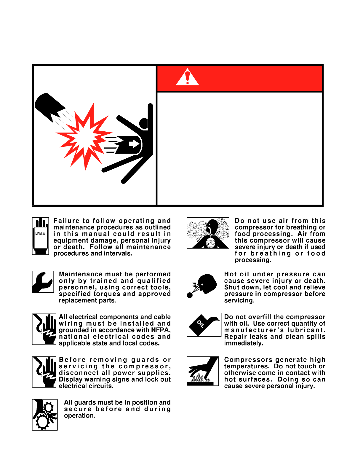
Read before operating your compressor!
EXPLODING T ANK WILL CAUSE
DEATH, SERIOUS INJURY
OR PROPERTY DAMAGE
●
Drain air tank after each use to prevent
moisture build-up and corrosion which
leads to tank failure.
Assure that tank and compressor relief
●
valves work properly, and are at correct
71393886
pressure settings.
DO NOT modify or repair air tank.
●
●
EVER drive vehicle with pressure in air
tank.
DANGER
Page 4

DA435HA: 99901219: iv
19980930
TABLE OF CONTENTS
PARA TITLE PAGE
SECTION 1. INTRODUCTION AND SPECIFICATIONS
1-1. INTRODUCTION ................................................................................................................ 1-1
1-2 ORDERING REPAIR PARTS ............................................................................................. 1-1
1-3. GENERAL INFORMATION................................................................................................. 1-1
1-4. SPECIFICATIONS.............................................................................................................. 1-1
SECTION 2. INST ALLATION
2-1. GENERAL .......................................................................................................................... 2-1
2-2. PTO AND PUMP INSTALLATION....................................................................................... 2-1
2-2-1. PTO INSTALLATION .......................................................................................................... 2-1
2-2-2. DRIVELINE AND PUMP INST ALLA TION ........................................................................... 2-2
2-3. COMPRESSOR INSTALLATION........................................................................................ 2-2
2-4. DRIVELINE INSTALLATION TECHNIQUES ...................................................................... 2-3
2-4-1. U-JOINT OPERATING ANGLES ........................................................................................ 2-3
2-4-2. SINGLE PLANE AND COMPOUND U-JOINT OPERATING ANGLES............................... 2-3
2-4-3. ELIMINA TING COMPOUND ANGLE INDUCED VIBRATION............................................. 2-4
2-4-4. ANGLE SIZE ...................................................................................................................... 2-5
SECTION 3. OPERA TION
3-1. GENERAL .......................................................................................................................... 3-1
3-2. OPERATION ...................................................................................................................... 3-1
SECTION 4. MAINTENANCE & PARTS
4-1. GENERAL .......................................................................................................................... 4-1
ROUTINE MAINTENANCE CHECKLIST ........................................................................... 4-1
OIL COOLING SYSTEM............................................................... 200057......................... 4-2
COMPRESSOR MOUNTING SYSTEM .......................................200056-1 ..................... 4-3
COMPRESSOR ASSEMBLY........................................................200056-2 ..................... 4-4
COMPRESSOR ASSEMBLY........................................................200056-3 ..................... 4-5
COMPRESSOR ASSEMBLY........................................................200056-4 ..................... 4-6
CANOPY SYSTEM............................................................................................................. 4-7
COMPRESSOR WIRING DIAGRAM.................................................................................. 4-8
INSTALLA TION KIT......................................................................51712642..................... 4-9
DECAL PLACEMENT......................................................................................................... 4-10
HYDRAULIC INST ALLATION KIT ................................................91707052..................... 4-11
DRIVELINE MOUNTING OPTION ...............................................31701761..................... 4-12
REPAIR KITS ..................................................................................................................... 4-12
SECTION 5. REP AIR
5-1. GENERAL .......................................................................................................................... 5-1
5-2. PISTON RING REPLACEMENT ........................................................................................ 5-1
5-3. OIL PUMP REPLACEMENT............................................................................................... 5-2
5-4. CRANKSHAFT AND BEARING REPLACEMENT .............................................................. 5-2
5-5. TROUBLESHOOTING ....................................................................................................... 5-4
SECTION 6. RELAY BOARD OPERATION
6-1. INTRODUCTION ................................................................................................................ 6-1
6-2. OPERATION ...................................................................................................................... 6-1
6-2-1. IGNITION “ON”................................................................................................................... 6-1
6-2-2. REMOTE STARTING THE VEHICLE................................................................................. 6-1
6-2-3. REMOTE ENGINE STOP................................................................................................... 6-1
6-2-4. REMOTE ENGINE SPEED (FROM CRANE)..................................................................... 6-3
6-2-5. COMPRESSOR ENGINE SPEED CONTROL (COMPRESSOR ONLY) ........................... 6-3
6-2-6. ENGINE SPEED CONTROL (CRANE&COMPRESSOR USED SIMULTANEOUSLY) ...... 6-3
6-3. INSTALLATION .................................................................................................................. 6-7
Page 5
DA435HA: 99901219: 1-119980930
SECTION 1. INTRODUCTION AND SPECIFICATIONS
1-1. INTRODUCTION
This manual provides information on the
installation, operation and repair of the IMT Model
DA435HA Hydraulic Air Compressor.
Three means are used throughout this manual to gain
the attention of operating and service personnel.
They are NOTES, CAUTIONS and WARNINGS
and are defined as follows:
NOTE
A NOTE IS USED TO EITHER CONVEY ADDITIONAL
INFORMATION OR TO PROVIDE FURTHER EMPHASIS
FOR A PREVIOUS POINT.
CAUTION
A CAUTION IS USED WHEN THERE IS THE STRONG
POSSIBILITY OF DAMAGE TO THE EQUIPMENT OR
PREMA TURE EQUIPMENT FAILURE.
WARNING
A W ARNING IS USED WHEN THERE IS THE POTENTIAL
FOR PERSONAL INJURY OR DEATH.
Operate this equipment with respect and service it
regularly for a safer working environment and
longer equipment life.
1-2. ORDERING INFORMATION
When placing orders or requesting assistance, refer
to the information below:
1-3. GENERAL INFORMATION
The IMT DA435HA air compressor is a single
stage, air cooled, 4-cylinder, pressure lubricated,
hydraulically driven unit, with a delivery rate of
35 CFM at 100 PSI.
CAUTION
OPERATING THE COMPRESSOR AT PRESSURES
ABOVE 150 PSI WILL SHORTEN THE SERVICE LIFE
AND VOID THE WARRANTY.
1-4. SPECIFICATIONS
Power Source Hydraulic Motor
Bore 2-5/8"
Stroke 2-1/2"
Cylinder Configuration V4
Dimensions 26-1/2"L x 19-1/8"H* x 19-3/4"W
Displacement 44 CFM**
Delivery 35 CFM**
Cooling Air
Fan Diameter 14-1/8"
Operating Speed 1400 RPM maximum
Lubrication Oil Pump
Oil Capacity 1-1/3 qts
Weight 200 lbs.
Reservoir requirement 12 Gallon minimum
Normal GPM @1400rpm 9.3 GPM
Normal Operating PSI 1850 PSI
Maximum PSI 2400 PSI
* Add 2-5/8” to height for air filter cap.
** @ 1400 RPM - 100 PSI
TRANSMISSION MAKE:
PTO NUMBER:
COMPRESSOR MODEL:
PUMP MAKE:
RESERVOIR CAPACITY:
TO BE COMPLETED BY DEALER
CHASSIS INFORMA TION
MODEL:
PTO %:
COMPRESSOR AND HYDRAULIC PUMP INFORMATION
SERIAL NUMBER:
MODEL:
ENGINE RPM:
Page 6

DA435HA: 99901219: 1-219980930
NOTES
Page 7
DA435HA: 99901219: 2-1
19980930
SECTION 2. INSTALLATION
2-1. GENERAL
This section pertains to the installation of the IMT
DA435HA compressor, PTO and pump. The
instructions are intended as a guide to assist you
with your particular installation. These instructions
will provide only general information.
2-2. PTO AND PUMP INSTALLATION
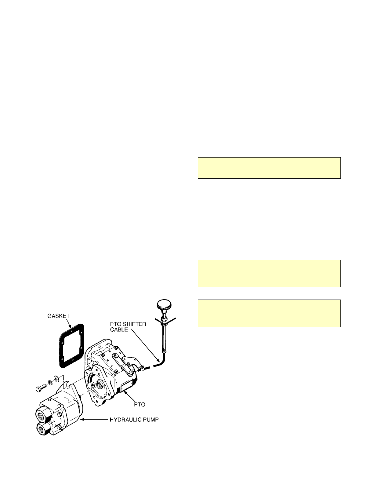
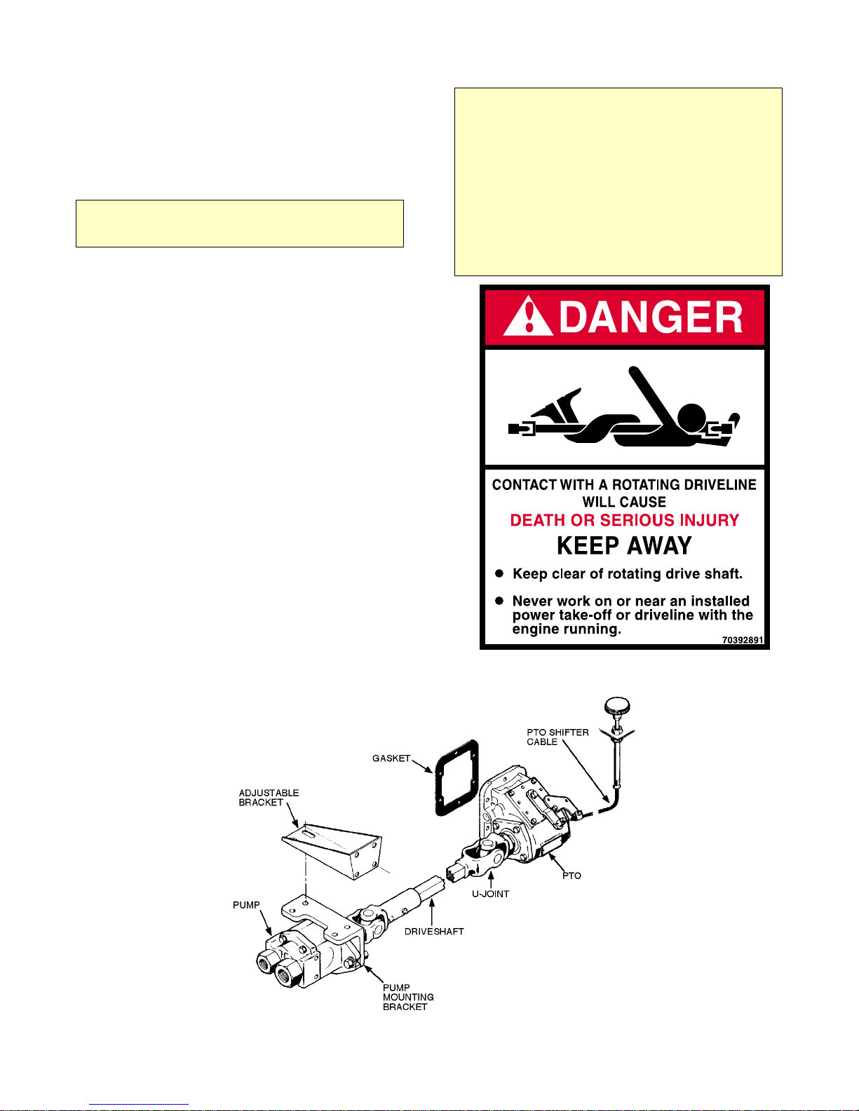
The pump may either be installed directly on the
PTO (see Figure B-1) or, as an optional method, it
may be driven by a driveline (see Figure B-2).
2-2-1. PTO INSTALLATION
Power take-off manufacturers provide specific
installation instructions for their products. Those
instructions should be followed when installing a
PTO. Check with the PTO manufacturers
representative for specific instructions regarding
your particular make, model and year of vehicle.
The following instructions are a guide in this
application.
1. If the vehicle is new, drain the transmission oil
into a clean container for reuse. If the vehicle is
used, drain and dispose of the transmission oil
properly.
2. Temporarily install the PTO with the proper
gaskets and only two studs. Snug the PTO down
and check the backlash for maximum allowance of
.006" to .012". If the backlash is excessive, remove
gaskets and check backlash again until it is
corrected.
3. Remove the PTO and apply Permatex® to the
gaskets. If the holes for the studs are tapped through
the transmission housing, apply Permatex to the
studs and tighten them down. Make certain that the
studs do not interfere with the transmission gears.
CAUTION
AVOID CONTACT OF PERMATEX WITH
TRANSMISSION FLUID.
Registered Trademark of Permatex Co., Inc., Kansas City, Kansas
4. Install the PTO and gaskets. Torque the nuts to
30 - 35 ft-lbs (4.14 - 4.84 kg-m) for a 6-bolt PTO
and 45 - 50 ft-lbs (6.22 - 6.91 kg-m) for 8-bolt
PTOs. Recheck the backlash.
5. Install the shifter cable to suit conditions.
Always allow for a slight overshift on lever or knob
to ensure the PTO is fully disengaged.
CAUTION
IT IS IMPORTANT THAT ADEQUATE SPACE BE
ALLOWED FOR FULL ENGAGEMENT OF THE PTO.
MODIFY THE EXHAUST OR OTHER OBSTRUCTIONS
AS NEEDED.
FIGURE B-1. PTO INSTALLATION
CAUTION
AVOID SHARP BENDS IN THE SHIFTER CABLE. ALL
BENDS SHOULD HAVE AT LEAST A 6" RADIUS.
TIGHTER BENDS WILL CAUSE DIFFICUL T OPERA TION
OF THE SHIFTER KNOB.
6. Replace the transmission oil. If the PTO is
located below the transmission oil level, an
additional quantity of oil will be required.
7. Start the engine, engage the PTO and check for
proper PTO rotation. Allow it to run for 5 - 10
minutes. Check for leaks, unusual noise and proper
operation.
8. Retorque the mounting bolts.
Page 8
DA435HA: 99901219: 2-2
19980930
2-2-2. DRIVELINE AND PUMP
INSTALLATION
The pump may be driven as shown in Figure B-2 as
an optional method to the one shown in Figure B-1.
The following steps are a guide in this application.
NOTE
BEFORE INSTALLING DRIVELINE, REFER TO
PARAGRAPH 2-4 FOR PROPER DRIVELINE
INST ALLATION TECHNIQUES.
1. Install the PTO (refer to Paragraph 2-2-1).
2. Loosely bolt the pump mounting bracket (A) to
the adjustable bracket (B) in Figure B-2.
3. Bolt the adjustable bracket to the frame at a
point that will not exceed 48" (122cm) from the
PTO and will not cause a joint angle greater than 3°.
4. Check the pump rotation and install pump, pump
end yoke and PTO end yoke.
WARNING
THE INSTALLER OF THE DRIVELINE MUST INSPECT
THE FINAL POSITION OF THE DRIVELINE TO
DETERMINE WHETHER ITS LOCATION PROVIDES
SUFFICIENT PROTECTION TO AN OPERATOR, OR
OTHER PERSONNEL, FROM HAZARDS ASSOCIATED
WITH A ROTATING DRIVELINE. IF PROTECTION IS
INSUFFICIENT, THE INSTALLATION OF A GUARD IS
REQUIRED. IF YOU ARE UNSURE OF METHODS TO
GUARD A ROTATING DRIVELINE, CALL IOWA MOLD
TOOLING CO., INC. FOR INSTRUCTIONS. FAILURE
TO DO SO MAY RESULT IN SERIOUS INJURY OR
DEATH.
5. Size, cut and weld the driveline to the necessary
length. Ensure driveline balance and run out meet
specification. Allow 1" (2.54cm) extra for PTO end
yoke.
6. Install driveline in phase with proper operating
angle calculations, lock set screws and grease Ujoints and mating spline.
7. Ensure all mounting bolts are tight.
2-3. COMPRESSOR INSTALLATION
See Installation Kit Drawing in the Parts Section for
specific installation and parts information.
FIGURE B-2. DRIVELINE & PUMP INSTALLATION
Page 9

DA435HA: 99901219: 2-319980930
2-4. DRIVELINE INSTALLATION
TECHNIQUES
2-4-1. U-JOINT OPERATING ANGLES
Every U-joint that operates at an angle creates
vibration.
U-joint operating angles are probably the most
common cause for driveline vibration in vehicles
that have been reworked or that have had auxiliary
equipment installed.
When reworking a chassis or installing a new
driveshaft in a vehicle, make sure that you follow
the basic rules that apply to u-joint operating angles,
as follows:
1. U-joint operating angles at each end of a shaft should
always be at least 1°.
2. U-joint operating angles on each end of a driveshaft
should always be equal within 1° of each other.
2-4-2. SINGLE PLANE AND COMPOUND
U-JOINT OPERATING ANGLES
There are two types of u-joint operating angles,
single plane and compound.
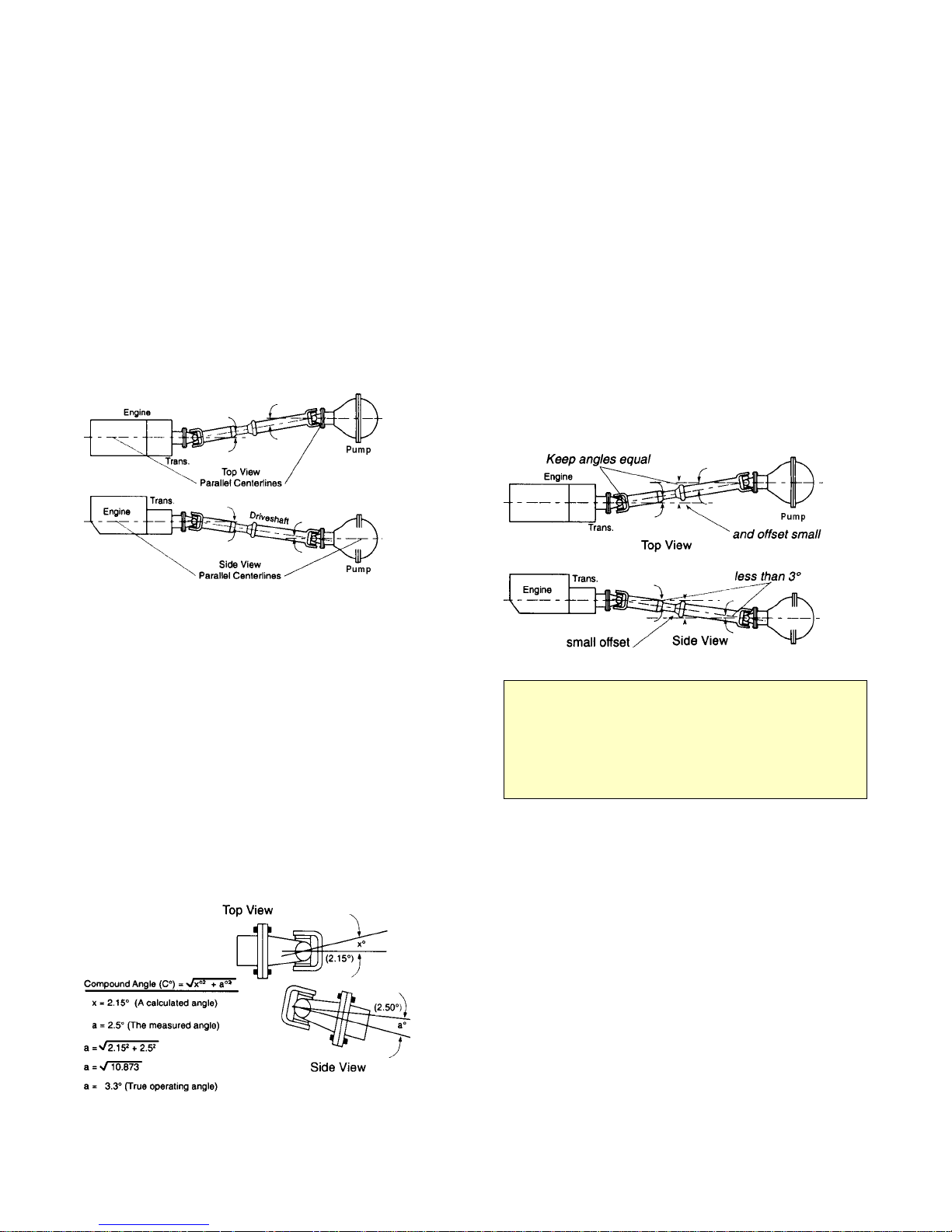
SINGLE PLANE
Single plane angles occur when the transmission and
pump components are in line when viewed from
either the top or side, but not both.
Determine the u-joint operating angle in an
application where the components are in line when
viewed from the top, but not in line when viewed
from the side, is as simple as measuring the slope of
the components in the side view, and adding or
subtracting those slopes to determine the angle. See
figure.
3. U-joint operating angles should not be larger than 3°. If
more than 3°, make sure they do not exceed the
maximum recommended angles for the RPM at which
they will be operating.
A u-joint operating angle is the angle that occurs at each
end of a driveshaft when the output shaft of the
transmission and the input shaft of the pump are not in
line. See figure.
The connecting driveshaft operates with an angle at
each u-joint. It is that angle that creates a vibration.
REDUCING AND CANCELING VIBRATION
A key point to remember about u-joint operating
angles: To reduce the amount of vibration, the
angles on each end of a driveshaft should always be
SMALL.
To cancel an angle vibration, the u-joint operating
angles need to be EQUAL within 1° at each end of a
shaft. See figure.
These angles should be SMALL and equal within 1°.
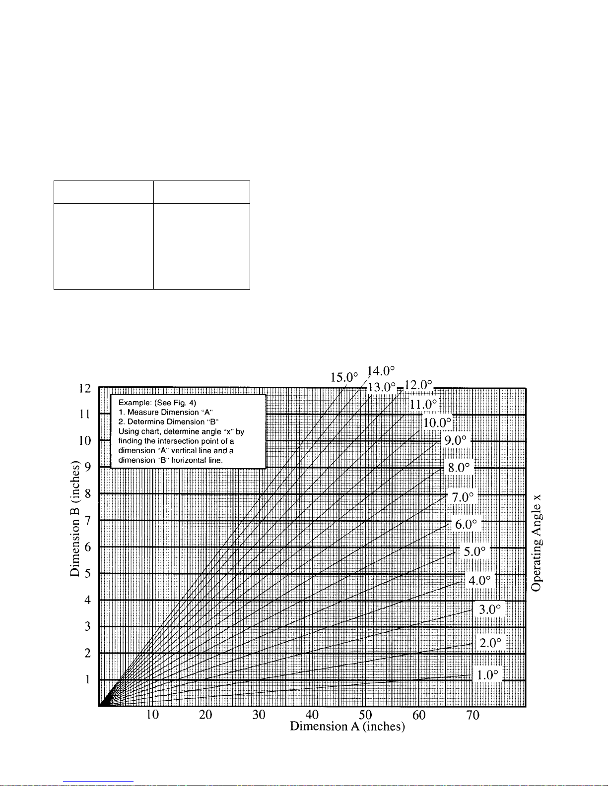
Determine the u-joint operating angles on a shaft
that is straight when viewed from the side and offset
when viewed from the top requires the use of a
special chart (See accompanying chart). In this type
of application, the centerlines of the connected
components must be parallel when viewed from the
top, as shown. These angles should also be SMALL
and equal within 1°. See figure.
Look at the angle chart and note that the smaller the
offset, the smaller the resultant angle.
To reduce the possibility of vibration, keep any
offset between connected points to a minimum.
Page 10
DA435HA: 99901219: 2-419980930
There are two things which can be done to make
certain single plane angles are SMALL and
EQUAL:
Make sure that the transmission and pump are mounted
so that their centerlines are parallel when viewed from
both the side and the top.
Make sure the offset between them is mall in both views.
COMPOUND ANGLES
Compound u-joint operating angles occur when the
transmission and pump are not in line when viewed
from both, the top and side. Their centerlines,
however, are parallel in both views. See figure.
Do the same for the other end of the shaft. Compare
the resultant calculated u-joint operating angle for
each end. They should be EQUAL within 1°. If they
are not, the driveshaft will vibrate.
2-4-3. ELIMINATING COMPOUND
ANGLE INDUCED VIBRATIONS
Compound u-joint operating angles are one of the
most common causes for driveline vibration. To
avoid thease problems, remember these important
considerations:
When setting up an application that requires compound ujoint operating angles, always keep the centerlines of the
transmission and pump parallel in both views.
Always keep the offset between their horizontal and
vertical centerlines small.
TRUE U-JOINT OPERATING ANGLE
The true u-joint operating angle, which must be
calculated for each end of the shaft with compound
angles, is a combination of the u-joint operating
angle in the top view, as determined from the chart,
and the measured u-joint operating angle in the side
view.
To determine the true u-joint operating angle for one
end of a shaft, (compound angle C° in the formula
shown in figure below) insert the u-joint operating
angle measurement obtained in the side view and the
u-joint operating angle obtained from the chart into
the formula.
NOTE
CENTERLINES OF TRANSMISSION AND AXLE MUST
BE PARALLEL IN BOTH TOP AND SIDE VIEWS TO USE
THIS METHOD OF DETERMINING TRUE U-JOINT
OPERATING ANGLE. CONTACT IMT TECHNICAL
SUPPORT IF YOU HAVE AN APPLICATION WHICH
CANNOT BE INSTALLED WITH THEIR CENTERLINES
PARALLEL.
Page 11
DA435HA: 99901219: 2-519980930
2-4-4. ANGLE SIZE
The magnitude of a vibration created by a u-joint
operating angle is proportional to the size of the ujoint operating angle. IMT recommends true u-joint
operating angles of 3° or less.
Obtain the true u-joint operating angle, as explained
above, and if it is greater than 3°, compare it to the
following chart.
The angles shown on the chart are the MAXIMUM
u-joint operating angles recommended by IMT and
are directly related to the speed of the driveshaft.
Any u-joint operating angle greater than 3° will
lower u-joint life and may cause vibration.
Remember to check maximum safe driveshaft RPM
as recommended by the driveshaft manufacturer.
DRIVESHAFT
RPM
5000 3.2°
4500 3.7°
4000 4.2°
3500 5.0°
3000 5.8°
2500 7.0°
2000 8.7°
1500 11.5°
OPERATING ANGLE
MAXIMUM
ANGLE CHART
FOR DRIVESHAFTS HAVING AN ANGLE IN THE TOP VIEW
Page 12

DA435HA: 99901219: 2-619980930
Page 13

DA435HA: 99901219: 3-119980930
SECTION 3. OPERATION
3-1. GENERAL
Each compressor is bench tested under load at the
factory to ensure proper break-in and operation.
While it is not necessary to follow any break-in
procedure, the following checks should be made
before putting the unit into service, as well as,
periodically during use.
1. Before start-up:
A. Check the oil level in the compressor
crankcase with the dipstick on the unit. If oil is
needed, use only IMTs synthetic compressor
oil. Always check compressor oil level with the
truck and compressor on level ground.
B. Check the air intake filter to make certain
that it is clean and unobstructed. A dirty filter is
a possible cause of reduced air output.
C. Avoid operating the compressor package
when the side-to-side or front-to-rear tilt is
greater than 20°.
2. With the compressor engaged:
Adjust engine speed to ensure that compressor
speed does not exceed 1400 RPM (max) under
load. Crack open air discharge valve until air
pressure drops to 140 PSI and maintains this
pressure without cycling. Doing so simulates a
maximum load condition.
3-2. OPERATION
To use the compressor, start the vehicle engine and
engage the compressor by operating the compressor
switch.
The system will now function automatically. It will
engage the hydraulic solenoid when the air pressure
is below 120 psi, and disengage when the air
pressure reaches 150 psi.
CAUTION
OPERATING THIS UNIT IN EXCESS OF 1400 RPM,
WILL VOID THE WARRANTY , AND WILL SHORTEN THE
NORMAL SERVICE LIFE OF THE COMPRESSOR.
If engine speed increase is required, readjust air
discharge valve to 140 PSI after speed has been
increased. Repeat until appropriate compressor
RPM (NOT engine) is acheived.
Checking compressor RPM can be done using a
phototach on the drive coupling through the air
cleaner access hole. A hydraulic flow meter can
be used, but is nat as accurate.
Page 14

DA435HA: 99901219: 3-219980930
NOTES
Page 15
DA435HA: 4-199901219: 19980930
Section 4. MAINTENANCE & PARTS
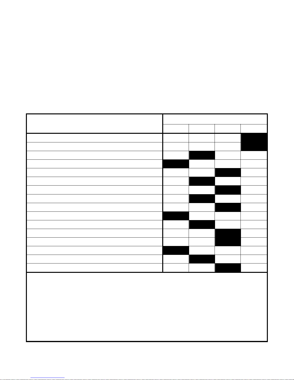
4-1. GENERAL
The following table provides list of routine
maintenance items, including service intervals. The
remainder of Section 4 includes a part lists and
assembly drawings of the compressor.
SERVICE INTERVALS
MAINTENANCE OPERATION
INSPECT DRIVE COUPLING FOR WEAR
AIR CLEANER - CHANGE
AIR INTAKE - INSPECT
CRANKCASE OIL LEVEL - CHECK, ADD IF NEEDED
CRANKCASE OIL - CHANGE (SEE NOTE 1)
CHECK CYLINDER HEAD STUD TORQUE (SEE NOTE 2)
COOLING VANES (FINS) - CLEAN
SAFETY VALVES - CHECK OPERATION
SAFETY VALVES - CLEAN
AIR RECEIVER - DRAIN CONDENSATION
RECEIVER SAFETY VALVES - CHECK OPERATION
TIGHTEN AND CHECK ALL VAL VES
CHECK ALL ELECTRICAL CONNECTIONS
CHECK FITTINGS AND AIR LINES FOR LEAKS
INSPECT CHECK VAL VES FOR PROPER OPERATION
DAILY WEEKLY 250/3 500/6
INSPECT CHECK VALVES FOR CARBON BUILDUP
Service intervals are listed as hours/months, whichever occurs first.
Use only IMT’s synthetic compressor oil. The use of any other oil causes excessive carbon buildup, and will void the
warranty on the compressor.
NOTE 1.
Under normal operating conditions, oil changes are required every 3 months. When operating in a dirty environment,
change the oil and air filter more frequently as your particular operating conditions dictate. Oil capacity is 1-1/3 quarts.
NOTE 2.
Cylinder head stud torque MUST be checked after the initial 8-10 hours of operation. The compressor must be cold (room
temperature) before retorquing of studs. Torque studs to 240 in-lbs plus or minus 10 in-lbs.
FIGURE D-1. ROUTINE MAINTENANCE CHECKLIST
Page 16
DA435HA: 4-2
00200057.01: 20010925
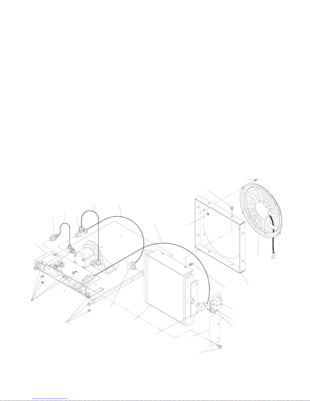
OIL COOLING SYSTEM (200057)
ITEM PART NO. DESCRIPTION QTY
200057 OIL COOLING SYSTEM 1
C1 80021 KIT HYD BLK N.O. SLND 1
301996 BLOCK-HYDRAULIC VALVE 1
301997 SOLENOID-HYDRAULIC 12VDC N.O. 1
301998 VALVE-RELIEF PILOTED SPOOL 1
C2 970508-106 CONNECTOR 1/2JIC 3/4SAE 1
C3 975508-019 HOSE ASM 1/2X19 SXE 1
C4 976512-1212 TEE 3/4NPT 3/4JIC MALE RUN 1
C5 975412-021 HOSE ASM 3/4X21” 2
C6 975412-029 HOSE ASM 1/2X29 SXS 1
C7 961504-090 NUT 1/4-20 TINNERMAN 4
C8 929705-075 BOLT 5/16-18X3 WHIZLOCK GR5 12
C9 974604-088 BOLT 1/4-20 HEX W/PL WASHER 4
C10 301577 FAN PUSHER 1
C11 300444 TAPE 1/16X3/4 CLOSED CELLO 2FT
C12 301434 SHROUD-OIL COOLER/FAN ASM 13 1
C13 961505-140 NUT 5/16-18 TINNERMAN 8
C14 300211 RELAY-POWER 2
C15 300909-025 CIRCUIT BREAKER 25A 1
C16 931600-050 SCREW 6-32X1/2 MACHINE 4
C17 973700-063 NUT #6-32 HEX NYLOC 1
C18 301433 BRACKET-OIL COOLER SIDE 35/17 1
C19 960212-050 ELBOW 1/2NPT 3/4JIC 2
C20 300836 OIL COOLER 12X13.5 1
C21 938205-071 WASHER 5/16 FLAT 6
C22 924305-166 NUT 5/16-18 NYLOC GR5 6
C23 301432 SUPPORT-OIL COOLER 35/175 RS 1
C24 929105-275 BOLT 5/16-18X2-3/4 HHGR5 2
C9
C1
C24
C21
C22
M10029
C2
C23
C8
C21
C22
C3
C4
C5
C19
C5
C20
C19
C6
C7
C18
C8
C13
C10
C11
C12
C14
C15
C16,C17
C8
Page 17
DA435HA: 4-300200056.01: 20100927
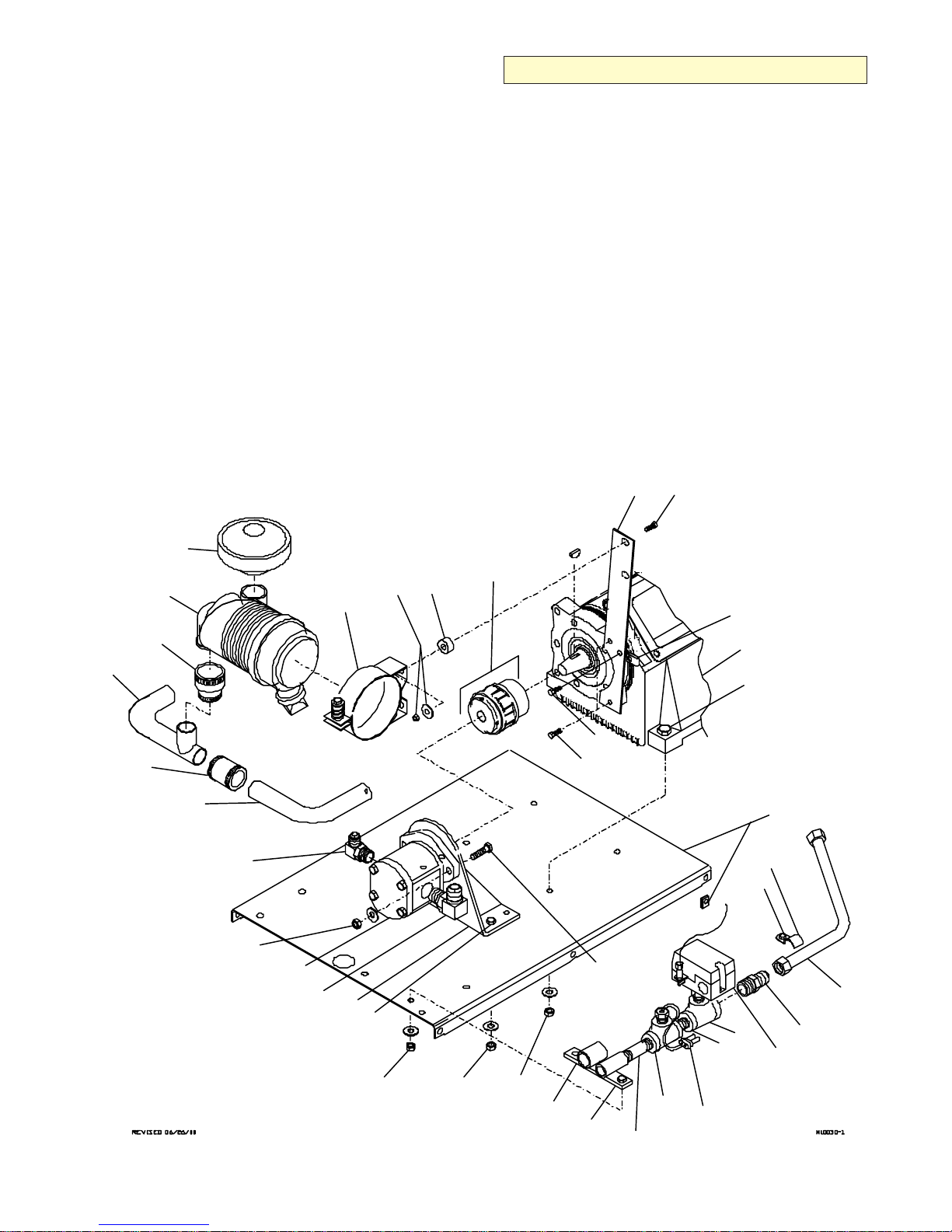
COMPRESSOR MTG SYSTEM (200056-1)
ITEM PART NO. DESCRIPTION QTY
M1 70000-001 COMPRESSOR REF
M2 929806-150 BOLT 3/8-16X1-1/2 HHGR8 6
M3 929704-050 BOLT 1/4-20X1/2 WHIZLOC 2
M4 301405 BASE 1
M5 961504-090 NUT 1/4-20 TINNERMAN 6
M6 978512-023 HOSE ASSY SS 3/4 1
M7 910212-075 CONNECTOR-TUBE 3/4X3/4NPT 1
M8 77041369 PRESSURE SWITCH W/UNLOADER 1
M9 961608-025 REDUCING NIPPLE 1/2X1/4NPT 1
M10 975200-025 INSERT-BRASS 2
M11 902203-022 REDUCER TEE 3/4X1/2X1/2 1
M12 922108-020 NIPPLE 1/2X2 SCH40 1
M13 301578 SWITCH-TEMP 1
M14 902415-020 TEE-PIPE 1/2 1
M15 922108-050 PIPE NIPPLE 1/2X5 SCH40 1
M16 929806-125 BOLT 3/8-16X1-1/4 HH 6
M17 301260 BRACKET 1
M18 938206-071 WASHER 3/8 FLAT 12
M19 925506-198 NUT 3/8-16 NYLOC GR8 12
M20 301248 BRACKET-HYD MTR MNT 1
M21 970412-106 ELBOW SAE#12 3/4JIC 1
M31
M34
M35
M30
M32
M29
M28
M33
CONTINUED ON FOLLOWING PAGE
ITEM PART NO. DESCRIPTION QTY
M22 301665 MOTOR-HYDRAULIC 1
M23 970408-088 ELBOW SAE#10 1/2JIC 1
M24 301928-125 CLAMP CONDUIT 1 1/4 1
M25 934504-075 SCREW TAP 1/4X3/4 1
M26 301430 TUBE-AIR INLET 1
M27 301418 SLEEVE 1
M28 301419 TUBE W/EXT 1
M29 301417 SLEEVE 1,75 ID X 1.25 ID 1
M30 70048241 AIR FILTER W/90° ELBOW 1
M31 300857 CAP-AIR FILTER 1
M32 300855 BAND-AIR FILTER MTG 1
M33 924305-166 NUT 5/16-18 NYLOC GR5 2
M34 938205-071 WASHER 5/16 FLAT 2
M35 301602 ISOLATOR 2
M36 301266 HUB-HYD MTR 1
M37 301267 SPIDER 1
M38 301265 HUB-CPRSR COUPLING 1
M39 301446 BRACKET-AIR FILTER 1
M40 929105-125 BOLT 5/16-18X1-1/4 HHGR5 2
M41 929405-125 BOLT5/16-24X1-1/4 HHGR5 1
M42 301628 WASHER-HUB RECIP 1
M43 300570-075 CLAMP 3/4 HOSE 1
M44 929105-100 BOLT 5/16-18X1 HHGR5 1
M45 925305-283 NUT 5/16-18 WHIZLOC 1
M39 M40
M36
M37
M38
M41
M42
M43
M45
M1
M2
M27
M26
M23
M18
M19
M22
M21
M20
M16
M18
M19
M18
M19
M18
M19
M17
M3
M16
M44
M2
M15
M14
M13
M12
M24
M25
M11
M4
M5
M6
M7
M8
M9
M10
Page 18

DA435HA: 4-400200056.02: 20061127
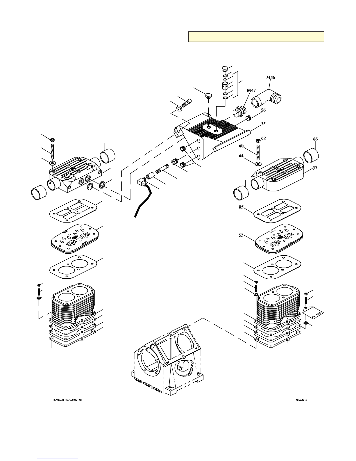
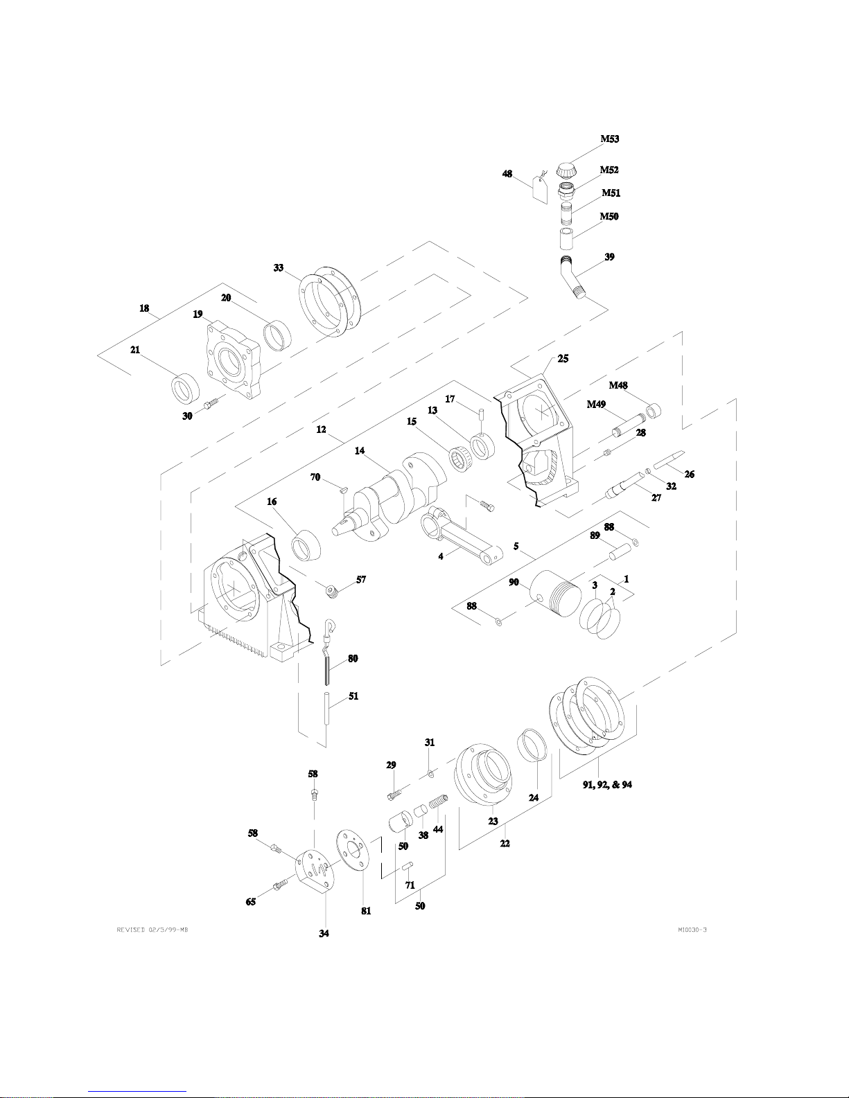
COMPRESSOR ASM (200056-2)
ITEM PART NO. DESCRIPTION QTY
200056 COMPRESSOR & MTG SYS REF
70000-001 COMPRESSOR REF
1. 51014947 RING SET-3 (INCL:2-3) 1
2. 70014599 COMPRESSION RING (part of 1) 8REF
3. 70014600 OIL RING (part of 1) 4REF
4. 51029283 CONNECTING ROD ASM 4
5. 51029285 PISTON ASM (INCL:88-90) 4
6. 7Q073017 O-RING (part of 47) 2REF
7. 70029468 SHIM (part of 47) 2REF
8. 76393085 O-RING (part of 47) 2REF
9. 72066426 BALL 19/32 STL (part of 47) 2REF
10. 70029593 INSERT (part of 47) 2REF
11. 51706913 CRANKCASE/CRANKSHAFT ASM
(INCL:12-33,91-94) 1
12. 51705661 CRANKSHAFT
(part of 11,INCL:13-17) 1REF
13. 60101269 OIL PUMP COLLAR (part of 12) 1REF
14. 60108748 CRANKSHAFT (part of 12) 1REF
15. 70055009 CONE BEARING (part of 12) 1REF
16. 70055012 CONE BEARING (part of 12) 1REF
17. 72066307 ROLL PIN .16X.44 (part of 12) 1REF
18. 51705709 FRT BRG HSG ASM
(part of 11,INCL:19-21) 1REF
19. 60025007 FRT BRG HSG (part of 18) 1REF
20. 70055011 CUP BEARING (part of 18) 1REF
21. 76039119 SEAL (part of 18) 1REF
22. 51705710 REAR BRG HSG ASM
(part of 11,INCL:23-24) 1REF
23. 60025005 REAR BRG HSG (part of 22) 1REF
24. 70055010 CUP BEARING (part of 22) 1REF
25. 60025012 CRANKCASE (part of 11) 1REF
26. 60120138 OIL SCREEN TUBE (part of 11) 1REF
27. 60120289 OIL SCREEN ([part of 11) 1REF
28. 72053403 PLUG 3/8 SH (part of 11) 1REF
29. 929105-100 CAP SCR 5/16-18X1 (part of 11) 5REF
30. 72060731 CAP SCR 5/16-18X3/4 SH(part of 11) 5REF
31. 938005-078 WASHER 5/16 LOCK (part of 11) 5REF
32. 72066008 OIL SCREEN CLAMP (part of 11) 1REF
33. 76039112 FRT BRG HSG GASKET(part of 11) 2REF
34. 60025006 REAR BRG HSG COVER 1
35. 60025193 PULSATION TANK 1
36. 60025194 CYLINDER BLOCK 2
37. 60025492 HEAD 2
38. 60101505 PLUNGER TRANSFER BUSHING 1
39. 60101507 BREATHER PIPE 1
40. 60106933 CHECK VALVE INSERT CAP 2
42. 7Q072212 O-RING 4
43. 76393107 O-RING 2
ITEM PART NO. DESCRIPTION QTY
44. 70014583 OIL PUMP SPRING 1
45. 70024122 WASHER .33X.5X.03 COPPER 12
46. 70029293 CYL BLOCK SPACER 2
47. 51714023 INSERT ASM (INCL:6-10) 2
48. 70039124 TAG-SYNTHETIC OIL 1REF
49. 70039300 DECAL-PATENT 1
50. 70051006 OIL PUMP 1
51. 70143153 DIPSICK 1
53. 70733069 REED VALVE ASM 2
56. 72053403 PLUG 3/8 SH 4
57. 72053404 PLUG 1/2 SH 1
58. 72053411 PLUG 1/8 SQHD 2
60. 72601708 STUD 5/16-18X3-1/2 12
62. 72062001 NUT 5/16-18 HEX 12
63. 72060063 CAP SCR 7/16-14X1-1/4 HHGR5 4
64. 72063001 WASHER 1/4 WRT 12
65. 72060731 CAP SCR 5/16-18X3/4 SH 4
66. 70392654M CAP 1-3/4 RUBBER 2REF
67. 70392654 COUPLING, RUBBER 2REF
69. 72063052 WASHER 7/16 LOCK 4
70. 72066267 WOODRUFF KEY .16X.62(part of 12) 1
71. 72661487 DRIVE PIN 1
79. 72601060 STUD 5/16X2 NC GR5 12
80. 73731843 DIPSTICK ASM 1
81. 76039093 PUMP COVER GASKET 1
82. 76039111 CYL BLOCK GASKET-BOTTOM 2
83. 76392119 CYLINDER BLOCK GASKET 2
84. 76392641 REED VALVE/CYL GASKET 2
85. 76392642 REED VALVE/HEAD GASKET 2
87. 72062036 NUT 5/16-24 HEX 12
88. 72066018 RET’G RING 5/8 STD INT(part of 5) 8REF
89. 70014627 PISTON PIN (part of 5) 4REF
90. 70029062 PISTON (part of 5) 4REF
91. 76039092 GASKET .006 (part of 11) 1REF
92. 76039094 GASKET .010 (part of 11) 1REF
94. 76039144 GASKET .020 (part of 11) 4REF
M10 975200-025 INSERT-BRASS 2
M46 981412-075 ELBOW-3/4JIC X 3/4 NPT LG 90° 1
M47 960412-075 NIPPLE 3/4MPT 3/4MPT HEX 1
M48 906130-015 PIPE CAP 3/8NPT 1
M49 922106-030 PIPE NIPPLE 3/8NPT X 3 1
M50 907215-020 PIPE COUPLING 1/2NPT SCH40 1
M51 923108-030 PIPE NIPPLE 1/2X3 GALV 1
M52 72531856 REDUCER COUPLING 3/4FPT 1
M53 70143495 BREATHER CAP 1
M54 907601-005 REDUCER BUSHING 3/8 1/8NPT 1
M55 922102-020 PIPE NIPPLE 1/8NPT X 2 SCH40 1
M56 907215-005 PIPE COUPLING 1/8 SCH40 GALV 1
M57 975104-012 ELBOW 1/8 X 1/4 90° COMPRSN 1
M58 89034176 TUBING 1/4 AIR BRAKE .75FT
CONTINUED ON FOLLOWING PAGE
Page 19
DA435HA: 4-5
00200056.03: 20010925
COMPRESSOR ASM (200056-3)
63
69
62
66
60
64
40
CONTINUED ON FOLLOWING PAGE
40
43
9
47
10
8
6
7
67
66
87
79
45
85
53
84
36
83
46
82
37
42
M57
M10
M58
M56
M55
M54
56
84
87
79
45
36
83
46
82
67
87
79
49
45
Page 20
DA435HA: 4-6
00200056.04: 19990209
COMPRESSOR ASM (200056-4)
Page 21
DA435HA: 4-7
CANOPY.01: 20010925
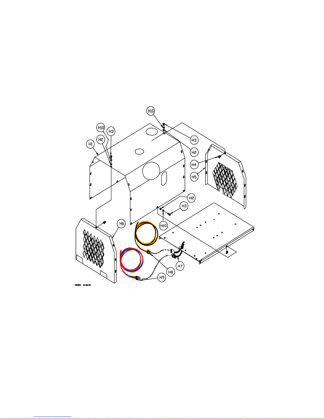
CANOPY SYSTEM
H1 301437 CANOPY 1
H2 977004-062 WASHER 1/4X.062X5/8 20
H3 983904-075 BOL T, ST A R DRIVE 1/4-20 x 3/4 20
H4 961504-090 NUT 1/4-20 TINNERMAN 14
H5 301436 PANEL-END RECIP 1
H6 301435 PANEL-END COOLER 1
H7 301381 HARNESS-35 RECIP 1
H8 301581 HARNESS-TOWER 3-WAY 1
H9 301607 HARNESS-SHROUD 3-WAY 1
H10 98404-071 WASHER, FLA T WIDE 1/4” SS 20
Page 22
DA435HA: 4-8
WIRING.01: 19990209
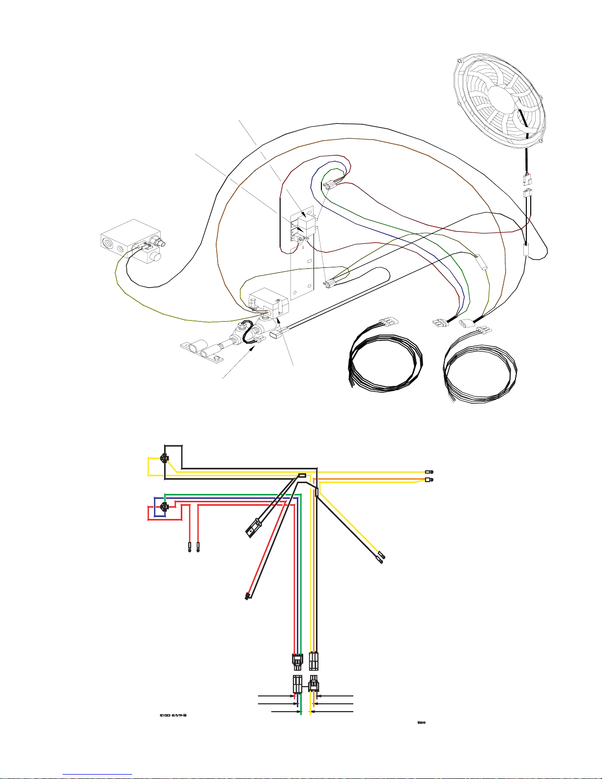
COMPRESSOR WIRING DIAGRAM
FAN
POWER RELAY
HIGH TEMPERATURE
SHUTDOWN
SWITCH RELAY
HYDRAULIC VALVE BLOCK ASM
W/ N.O. SOLENOID AND
RELIEF VALVES
COOLING
FAN ASM
M10033
HIGH TEMPERAT URE
SHUTDOWN SWITCH
SHUTDOWN RELAY
SOCKET
FAN RELAY
SOCKET
CIRCUIT
BREAKER
FURNAS
SWITCH
FURNAS
PRESSURE
SWITCH
SHUTDOWN
SWITCH
HYDRAULIC
SOLENOID
VALVE
FAN
BATTERY 12VDC
IGNITION 12VDC
PTO GROUND SIGNAL
CUSTOMER
CONNECTIONS
SYSTEM GROUND
SPEED CONTROL
COMPRESSOR ON
Page 23
DA435HA: 4-9
MOUNTING.01: 20050630
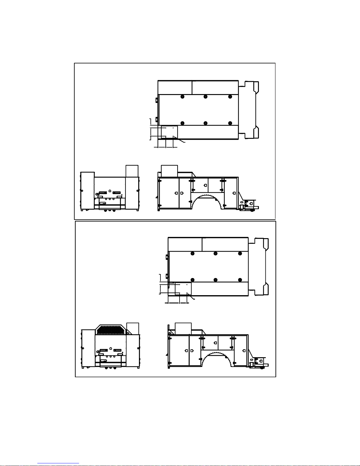
DA435HA MOUNTING LOCATIONS
(99903712)
DA435HA INSTALLATION ON SERIES 1 AND SERIES 2
DOMINATOR
4.40
13.38
12.75 12.00
DA435HA INSTALLATION ON SERIES 2
DOMINATOR WITH HEADACHE RACK
AND STANDARD HEIGHT SIDEPACK ON
COMPRESSOR SIDE
4.40
13.38
0.44 TYP. (4)
0.44 TYP. (4)
12.0018.75
Page 24
DA435HA: 4-10
51712642.01: 20010925
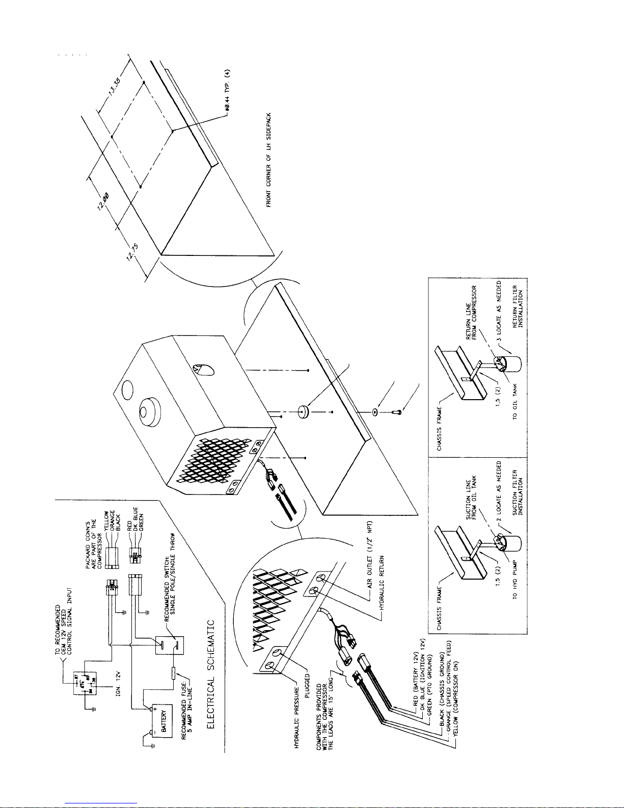
INSTALLATION KIT (51712642)
(THROUGH 3-15-05)
(INSTALLATION DWG 99901281 SHOWN)
ITEM PART NO. DESCRIPTION QTY
1. 76391527 BUMPER-RUBBER 4
2. 938206107 WASHER 3/8 FLA T GR8 (938206107) 4
3. 929106200 BOLT 3/8-16X2 HHGR5 4
4. 99901281 DRAWING 1
1 TYP (4)
2 TYP (4)
3 TYP (4)
Page 25
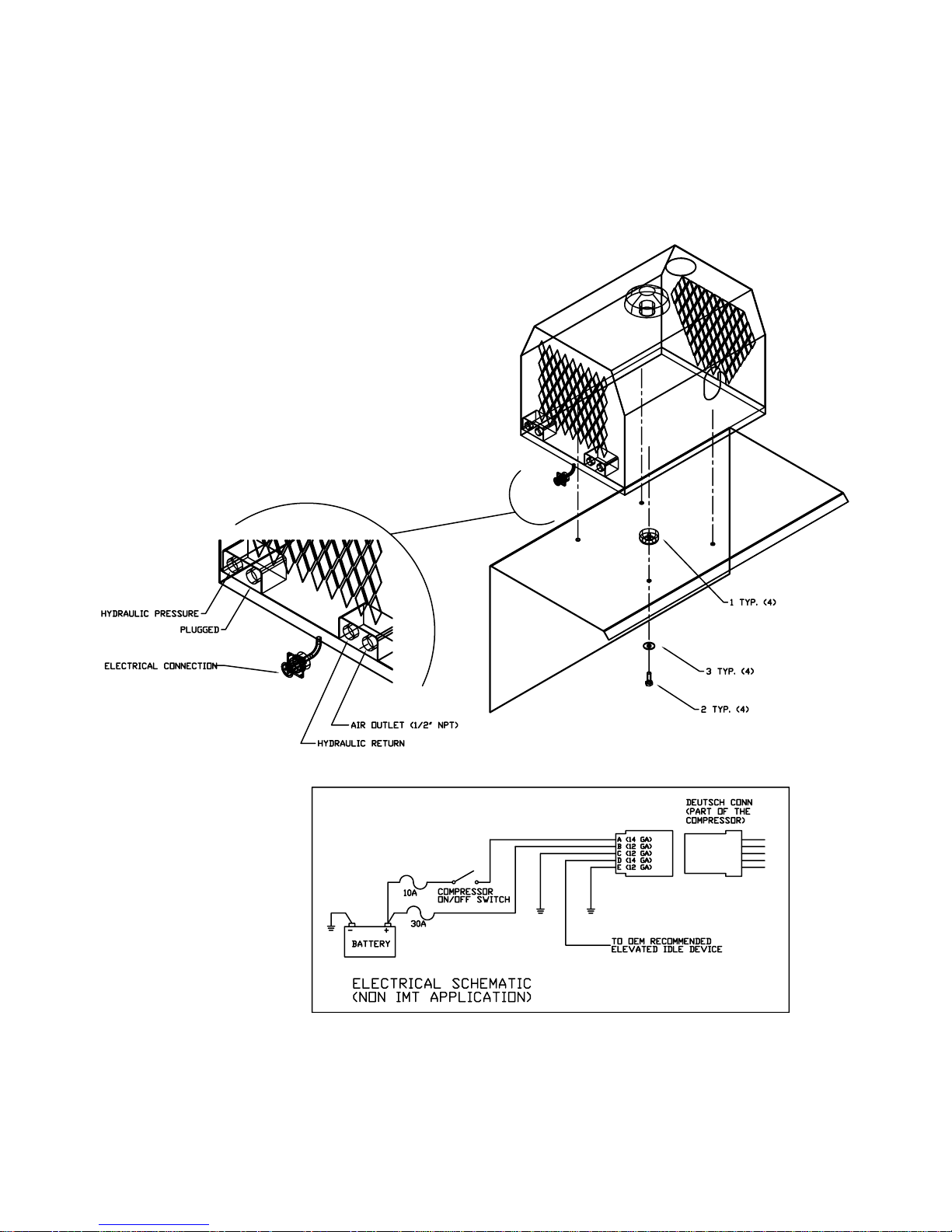
DA435HA: 4-1151712642.01: REV. B 20050630
INSTALLATION KIT (51712642)
(EFFECTIVE 3-15-05)
(INSTALLATION DWG 99901281 SHOWN)
ITEM PART NO. DESCRIPTION QTY
1. 76391527 BUMPER-RUBBER 4
2. 929106200 BOLT 3/8-16X2 HHGR5 4
3. 938206107 WASHER 3/8 FLA T GR8 4
Page 26
DA435HA: 4-12
20050629
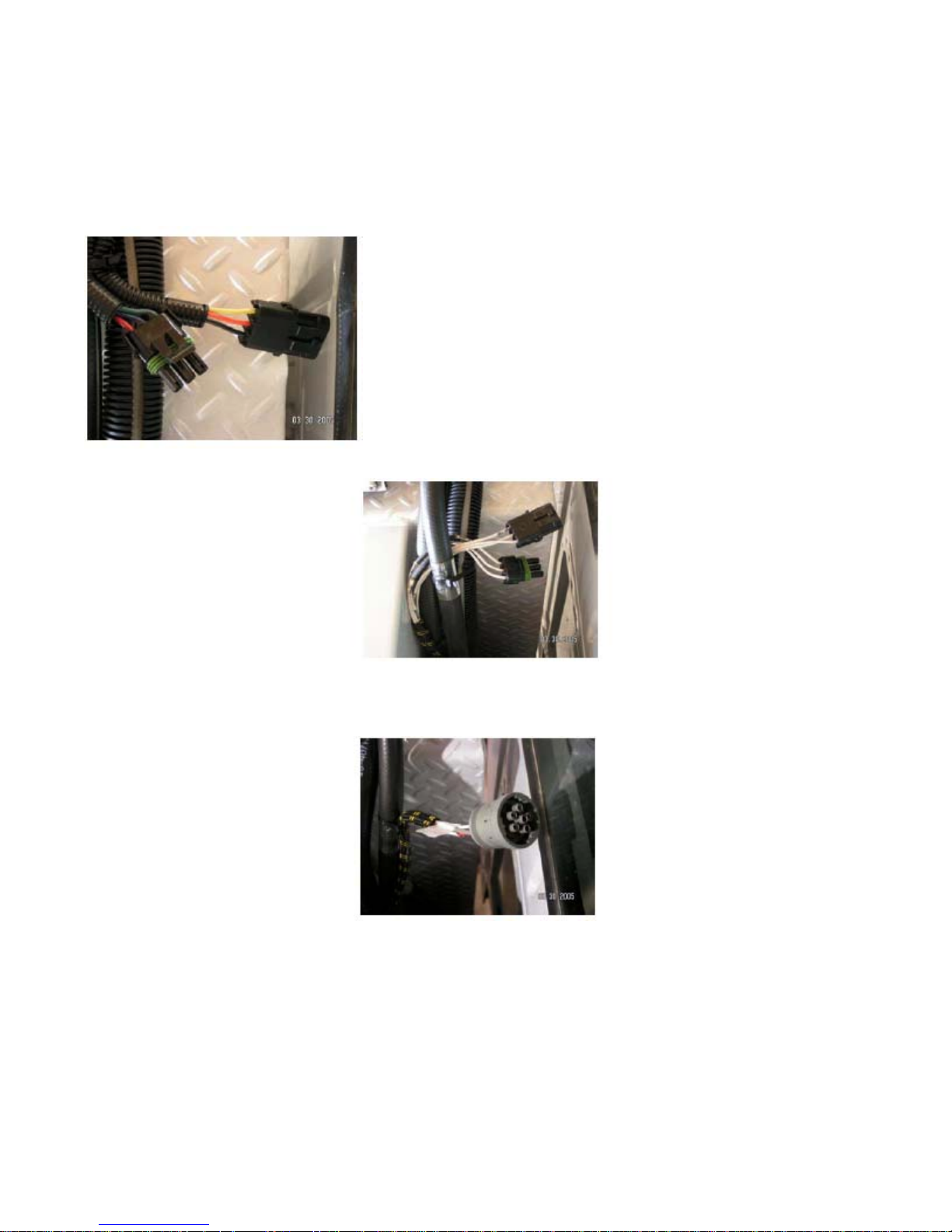
COMPRESSOR HARNESS CHART
Effective March 15, 2005, the connectors in the harnesses used on the DA435HA were upgraded. The old and new
connectors are not interchangeable, so for replacement parts, the correct harness and/or jumper must be ordered.
Use the following chart to determine the correct harness and/or jumper.
If your DA435HA connector looks like Connector A:
and your body connector looks like this: No jumper is needed.
and your body connector looks like this: Use jumper # 77441160.
If you are not using an IMT body and your connector looks like Connector A, use jumpers 301581 and 301607.
Page 27
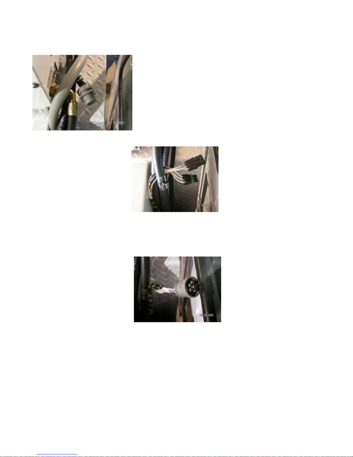
DA435HA: 4-13
20050630
COMPRESSOR HARNESS CHART, CONTINUED
If your DA435HA connector looks like Connector B:
and your body connector looks like this: Use jumper # 77441158.
and your body connector looks like this: No jumper is needed.
If you are not using an IMT body and your connector looks like Connector B, use jumper 77441157.
Page 28
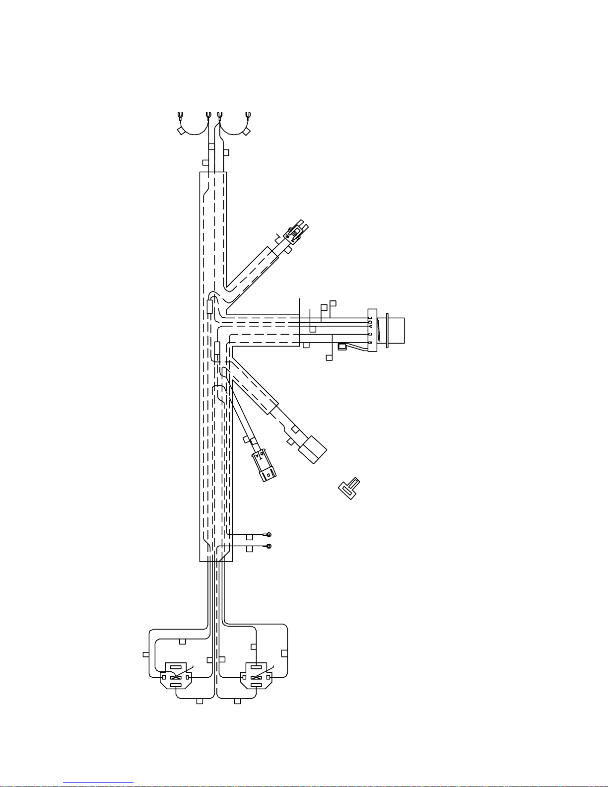
DA435HA: 4-14
E
304710: 20050629
HARNESS (304710) EFFECTIVE 3/15/05
LOCKING
#8 SPAD
4B
ORANGE 4A
FORKS
12
14 YELLOW
48
YELLOW
28
BLACK
14 YELLOW
SWITCH
11
3 YELLOW
2-WAY WP TOWER CONNECTOR
2 FEMALE TERMINALS
2 GRAY CABLE SEALS
BUTT
BUTT
9B BLACK
10 BLACK
14 RED
1
14 RED
8
4A
14 GA WIRE
9A
1
7
2C
14 BLACK
5
14 RED
MP 2 WAY MALE
SHUTDOWN SWITCH
TERMINAL, CABLE SEAL,
#10 RINGS
2A
WIRE TIE
CONNECTOR
FAN MOTOR
FEM TERMINAL AMP
PIN "F" IS
14 BLACK
ORANGE
YELLOW
DK GREEN
14 RED
TO LOOM
NOT USED
8-PIN CONNECTOR
YELLOW
3
20
BLACK
SHUTDOWN
SWITCH
87a
87
30
86
85
RELAY SOCKET
(LOAD VIEW)
BC
10 BLACK
YELLOW
7 DK GREEN
B
88
14 RED
6
14 RED
87
85
30
FAN POWER
CIRCUIT BREAKER
90
DK. BLUE
87a
RELAY SOCKET
(LOAD VIEW)
2 POSITION SPAL BODY SFL
ALL WIRE IS 16 GA GPT. EXCEPT 14 GA AS SHOWN.
Page 29
DA435HA: 4-15
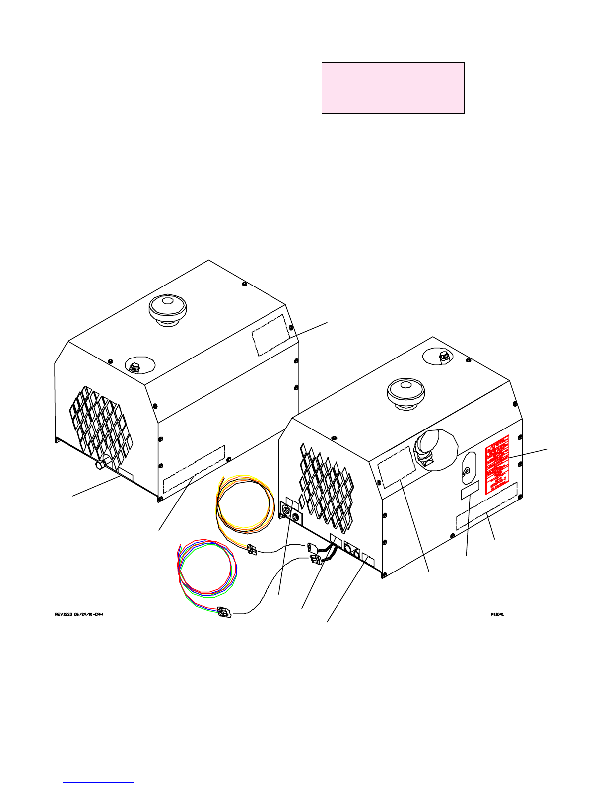
DECALS.01: 20030715
DECAL PLACEMENT (80015)
ITEM PART NO. DESCRIPTION QTY
I1 71393715 DECAL-DIAMOND AIR 2
I2 70395091 DECAL-DA435HA COMPRESSOR 2
I3 300913 DECAL-OIL DRAIN 1
I4 *300040 DECAL-DANGER BREATHING AIR 1
I5 *300042 DECAL-WARNING CONNECT AIR 1
I6 *300041 DECAL-WARNING FAN GUARD 1
I7 *301442 DECAL-DRIVE COUPLING 1
I8 301634 DECAL COMBO 1
I9 301480 SERIAL PLATE 1
I10 302265 DECAL - AIR 1
I11 302266 DECAL - HYD. TANK 1
I12 302267 DECAL - HYD. PRESSURE 1
* NOT SHOWN-SEE PLACEMENT CHART
DECAL PLACEMENT
ITEM LOCATION
I4 HOSE REEL COMPARTMENT
I5 HOSE REEL COMPARTMENT
I6 INSIDE CANOPY
I7 INSIDE CANOPY
I1
I8
I3
I2
I2
I9
I1
I10
I11
I12
Page 30
DA435HA: 4-16
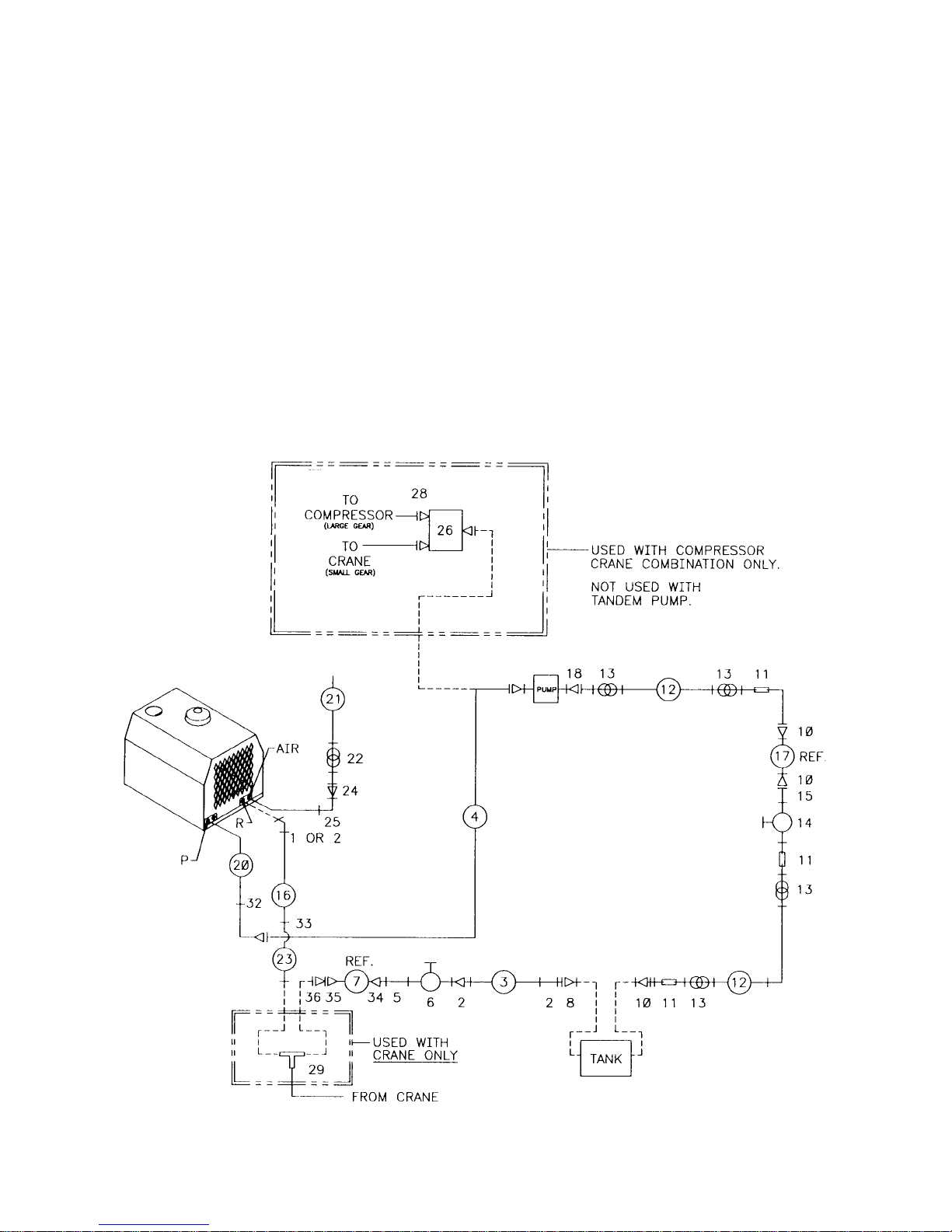
INSTALL: 20010925
HYDRAULIC INSTALLATION KIT
(91707052)
1. 72531427 ELBOW 3/4NPT #12MJIC 1
2. 72053676 ADAPTER 3/4MPT #12MJIC 3
3. 51707317 HOSE ASM 3/4X100 1
4. 51703585 HOSE ASM 1/2X220 FF 1
5. 72053141 PIPE NIPPLE 3/4NPT X CL 1
6. 73054129 GA T E V A L V E 3/4NPT 1
7. 73052040 HYD FILTR 25MIC 1-1/4FPT 1REF
8. 72053180 REDUCER BUSHING 1-1/4 3/4 1
9. 72532658 ELBOW #8MJIC #8FJIC 2
(NOT SHOWN)
10. 72053377 REDUCER BUSHING 1-1/4 1 3
11. 72431549 BARB NIPPLE 1MPT 1HOSE 3
12. 89039481 HOSE 1” 100R4 14FT
13. 72066515 HOSE CLAMP 1” 2-BOLT 4
14. 73054001 GA TE VALVE 1NPT 1
15. 72053185 PIPE NIPPLE 1NPTXCL 1
16. 51706446 HOSE ASM 3/4x35FF 1
17. 51709743 FILTER ASM 100-MESH 1REF
18. 72532712 BEAD NIPPLE #16MSTR 1” 45° 1
20. 51706981 HOSE ASM 1/2X35 1
21. 89392349 HOSE 3/4 300# 17”
22. 72066000 HOSE CLAMP SAE#12 1
23. 51704576 HOSE ASM 3/4X72FF 1
24. 72053458 BARB NIPPLE 3/4MPT 3/4HOSE1
25. 72053556 STREET ELBOW 3/4NPT 90° 1
26. 73054685 ROTARY FLOW DIVIDER 1REF
27. 72532358 ADAPTER 3REF
28. 72532376 HOSE FITTING 4REF
29. 72532695 TEE MJIC 1REF
30. 51711092 KIT-RELA Y BRD 1REF
31. 93710121 INSTALLA TION KIT W/CRANE 1REF
(INCLUDES 26-30)
32. 72533373 UNION BULKHD #8JIC 1
33. 72533371 UNION BULKHD #12JIC 1
34. 72531836 RED BUSHING 1-1/4 3/4NPT 1
35. 72533564 ADAPTER 1-1/4MPT #16MJIC 1
36. 72533028 ADAPTER #12MJIC #16FJIC 1
Page 31
DA435HA: 4-17
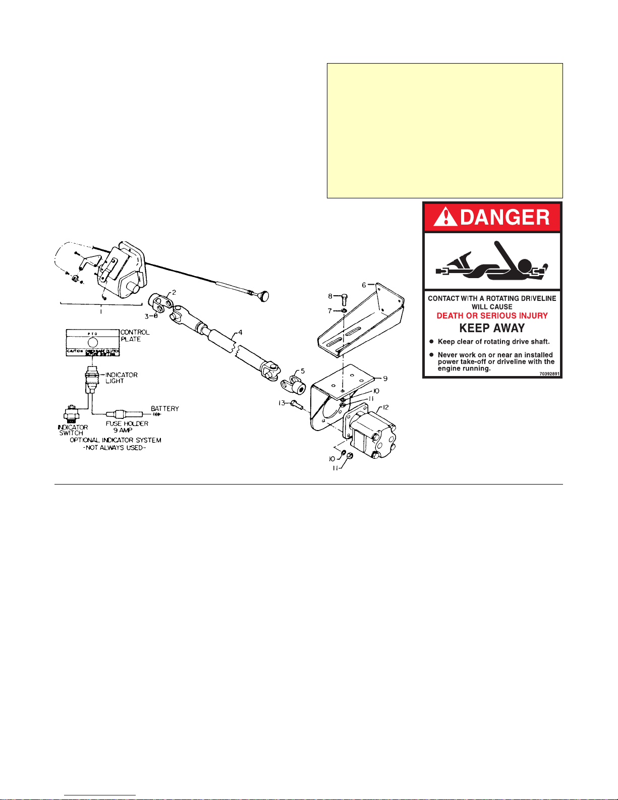
31701761.01: 19980930
DRIVELINE MOUNTING OPTION
(31701761)
ITEM PART NO. DESCRIPTION QTY
1. POWER TAKE-OFF REF
2. 70058146 END YOKE 1
3. 72060578 SET SCR 3/8-16X3/8 HH 1
4. 70058195 DRIVESHAFT ASM 1
5. 70058094 END YOKE 1
6. 60101988 MOUNTING BRACKET 1
7. 72063005 WASHER 1/2 WRT 4
8. 72060093 CAP SCR 1/2-13X1/2 HHGR5 4
9. 52703382 PUMP MOUNTING BRACKET 1
10. 72063053 WASHER 1/2 LOCK 8
11. 72062004 NUT 1/2-13 HEX 8
12 HYDRAULIC PUMP REF
13. 72060094 CAP SCR 1/2-13X1-3/4 HHGR5 4
WARNING
THE INSTALLER OF THE DRIVELINE MUST INSPECT
THE FINAL POSITION OF THE DRIVELINE TO
DETERMINE WHETHER ITS LOCATION PROVIDES
SUFFICIENT PROTECTION TO AN OPERATOR, OR
OTHER PERSONNEL, FROM HAZARDS ASSOCIATED
WITH A ROTATING DRIVELINE. IF PROTECTION IS
INSUFFICIENT, THE INSTALLATION OF A GUARD IS
REQUIRED. IF YOU ARE UNSURE OF METHODS TO
GUARD A ROTATING DRIVELINE, CALL IOWA MOLD
TOOLING CO., INC. FOR INSTRUCTIONS. FAILURE
TO DO SO MAY RESULT IN SERIOUS INJURY OR
DEATH.
GASKET KIT (51393217)
7Q072212 O-RING - CYL HEAD 4
76039092 GASKET-REAR BRG HSG .006 2
76039093 GASKET-PUMP COVER 1
76039094 GASKET-REAR BRG HSG .010 2
76039111 GASKET-CYL BLOCK BOTTOM 2
76039112 GASKET-FRT BRG HSG 2
76039119 SEAL 1
76039143 GASKET-REAR BRG HSG .015 2
76039144 GASKET-REAR BRG HSG .020 2
76392119 GASKET-CYL BLOCK 2
76392641 GASKET-REED V ALVE/CYL 2
76392642 GASKET-REED V AL VE/HEAD 2
REPAIR KITS
PISTON RING SET (51014947)
70014599 COMPRESSION RING 8
70014600 OIL RING 4
CRANKSHAFT KIT (51705743)
51705742 CRANKSHAFT ASM(INCL: KEY & CRANK) 1
70055010 BEARING-REAR CUP 1
70055011 BEARING-FRT CUP 1
70055012 BEARING-FRT CONE 1
70055009 BEARING-REAR CONE 1
72066307 DRIVE PIN 1
60101269 OIL PUMP COLLAR 1
Page 32

DA435HA: 4-18
99901219: 20000221
RECOMMENDED SPARE PARTS LIST
Model DA435HA Air Compressor
SHELF
ASSEMBLY LIFE ORDER
DESIGNATION ITEM NO. PART NO. DESCRIPTION QTY CODE (MO) QTY
0020057.01.19990209 OIL COOLING SYSTEM
C1 80009 CONTROLS-HYDRAULIC 1 C N/A
C10 301577 FAN PUSHER 1 C N/A
C11 300444 TAPE 1/16X3/4 CLOSED CELLO 2FT C N/A
C14 300211 RELAY-POWER 2 C N/A
C15 300909-025 CIRCUIT BREAKER 25A 1 C N/A
C20 300836 OIL COOLER 12X13.5 1 C N/A
00200056.01.19990209 COMPRESSOR MTG SYSTEM
M6 301605 TUBE ¾ AIR DISCHARGE 1 P N/A
M8 77041369 PRESSURE SWITCH W/UNLOADER 1 C N/A
M13 301578 SWITCH-TEMP 1 C N/A
M22 301665 MOTOR-HYDRAULIC 1 C N/A
M31 300857 CAP-AIR FILTER 1 C N/A
N/A 300854 REPLACEMENT AIR FILTER ELEMENT 1 C N/A
00200056.02.19990209 COMPRESSOR ASM
2 70014599 COMPRESSION RING 8 W N/A
3 70014600 OIL RING 4 W N/A
11 51706913 CRANKCASE/CRANKSHAFT ASM 1 W N/A
36 60025194 CYLINDER BLOCK 2 C N/A
38 60101505 PLUBGER TRANSFER BUSHING 1 C N/A
42 7Q072212 O-RING 4 C N/A
44 70014583 OIL PUMP SPRING 1 W N/A
45 70024122 WASHER .33X.5X.03 COPPER 12 W N/A
46 70029293 CYL BLOCK SPACER 2 W N/A
47 51714023 INSERT ASM 2 W N/A
50 70051006 OIL PUMP 1 C N/A
53 70733069 REED VALVE ASM 2 W N/A
66 70392654 CAP 1-3/4 RUBBER 2 C N/A
71 72661487 DRIVE PIN 1 C N/A
81 76039093 PUMP COVER GASKET 1 C N/A
82 76039111 CYL BLOCK GASKET-BOTTOM 2 C N/A
83 76392119 CYLINDER BLOCK GASKET 2 C N/A
84 76392641 REED VALVE/CYL GASKET 2 C N/A
85 76392642 REED VALVE/HEAD GASKET 2 C N/A
M53 70143495 BREATHER CAP 1 C N/A
CANOPY.01.19980930 CANOPY SYSTEM
H7 301381 HARNESS-35 RECIP 1 C N/A
H8 301581 HARNESS-TOWER 3-WAY 1 C N/A
H9 301607 HARNESS-SHROUD 3-WAY 1 C N/A
51712642.01.19990209 INSTALLATION KIT
91707052.01.19980930 HYDRAULIC INSTALLATION KIT
For additional instructions, see DOMINSTALL: 99901223: 19990812
1 76391527 BUMPER-RUBBER 4 W N/A
2 938206107 WASHER 3/8 FLAT GR8 4 W N/A
3 929106200 BOLT 3/8-16X2 HHGR5 4 W N/A
17 51709743 FIL TER ASM 100-MESH 1 P N/A
7 73052091 HYD FILTER 25/MIC-1 ¼ FPT 1 P N/A
Page 33
DA435HA: 99901219: 5-1
19980930
SECTION 5. REPAIR
5-1. GENERAL
This section describes the disassembly and assembly
procedures for the air compressor. In all cases,
remove the compressor from the vehicle before
proceeding with disassembly and repair within a
clean environment. Refer to the parts drawing in
section 4 of this manual for parts locations.
5-2. PISTON RING REPLACEMENT
1. Remove the pulsation tank.
2. Unscrew the head bolts and remove the heads.
NOTE
A RUBBER FACED MALLET WILL HELP WHEN
REMOVING THE HEAD. T AP THE SIDES OF THE HEAD
CAREFULLY UNTIL THE HEAD IS LOOSE. LIFT OFF
THE HEADS.
3. Remove the cylinder bolts. Tap the sides of the
cylinder several times to break it loose from the
gasket. Rock the cylinder back and forth and lift
until it is free. Lift it off the pistons.
8. With the ring expander, install the new ring kit.
Make certain that the oil ring is on the bottom and
the beveled inside edge of the compression ring is
toward the top of the piston.
9. Position the cylinder base gasket on the
crankcase. Use a few drops of oil to hold it in
position. Install the cylinder block spacer and gasket
on the crankcase.
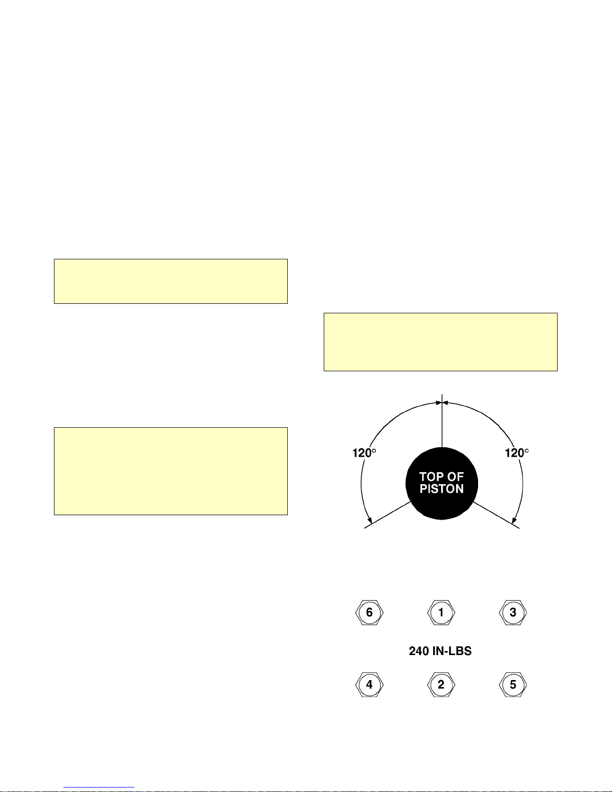
10. Rotate the rings so that the gaps of the three
rings are 120° apart. Lightly lubricate the inside of
the cylinder. Rotate the crankshaft so that a piston is
at the top of the stroke. Compress the rings with a
ring compressor, and slide the cylinder over the
piston. Repeat for the other piston.
CAUTION
DO NOT LUBRICATE THE RINGS. USE A LIGHT
LUBRICANT, SUCH AS WD-40 ONLY, ON THE
CYLINDER WALLS. OILING THE RINGS WILL
PREVENT THEM FROM SEATING AND CAUSE
EXCESSIVE OIL CONSUMPTION.
4. Use a single edged razor blade, or sharp
putty knife, to remove the old gasket material.
CAUTION
DO NOT ALLOW THE GASKET MA TERIAL T O FALL INTO
THE CRANKCASE. DO NOT NICK THE HEAD,
CYLINDER, OR CRANKCASE MATING FACES WHILE
REMOVING THE OLD GASKET. REMOVE ALL OF THE
OLD GASKET MATERIAL TO PROVIDE A SMOOTH,
CLEAN SURFACE FOR THE NEW GASKET. FAILURE
TO FOLLOW THIS PROCEDURE MAY RESULT IN THE
NEED TO RESEAL THE UNIT LATER.
5. Hone the cylinder to break the glaze and to
remove the buildup at the top of the cylinders.
6. Measure the inside diameter of the cylinder for
roundness and excessive wear. The bore should be
2.625" (0.0025" tolerance). If the bore is oversized,
the cylinder must be replaced.
7. With a ring expander, remove the compression
and oil rings.
FIGURE E-1. PISTON RING
ORIENTATION
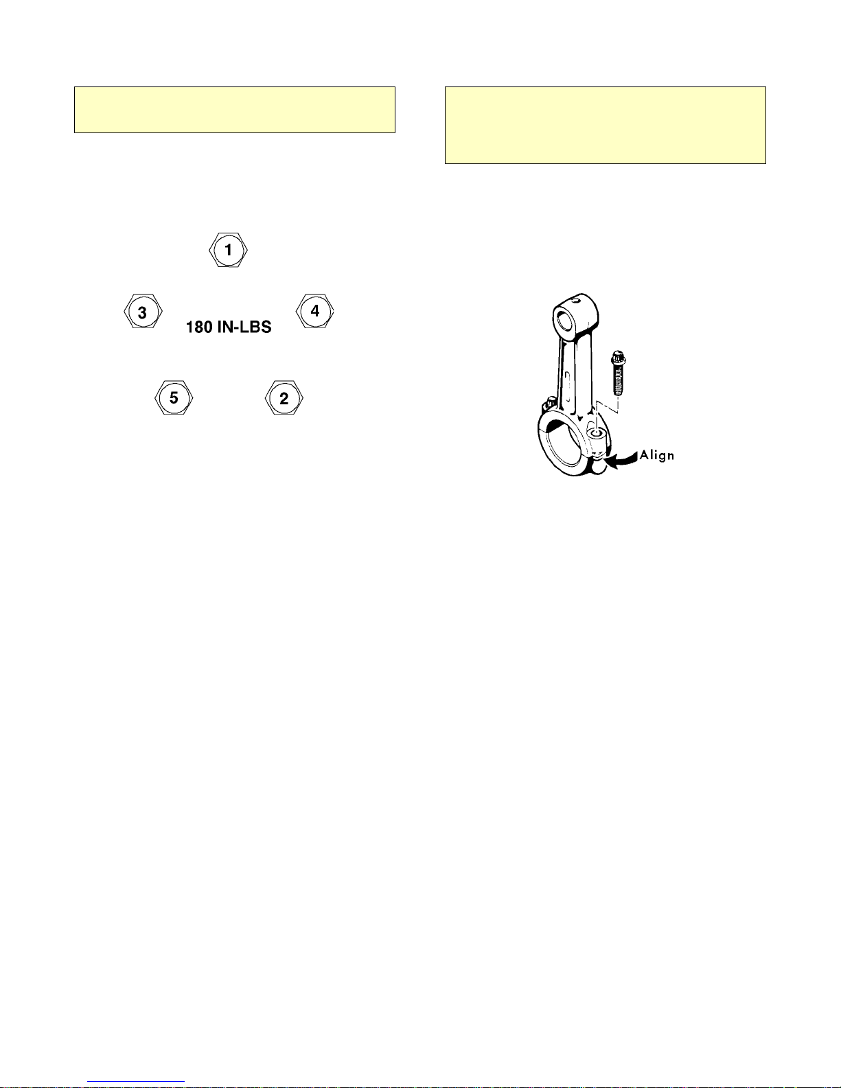
FIGURE E-2. CYLINDER HEAD TORQUE
SEQUENCE
Page 34

DA435HA: 99901219: 5-219980930
11. Slide the cylinder down until it mates with the
crankcase. Start all cylinder mounting bolts, until
they are snug. Torque the bolts to 180 in-lbs in the
sequence shown. Do not torque to the full 180 in-lbs
all at once, but in 25-50 in-lb increments.
12. Position the gaskets and valve plate on top of the
cylinder. Position the head on the cylinder and turn
studs finger tight. Torque the studs/nuts to 240 in-lbs
in 25-50 pound increments per Figure E-2.
NOTE
INSTALL THE VALVE PLATE WITH THE MARKED
SURFACE FACING UP.
7. Insert the two remaining bolts and torque to 180
in-lbs. The bolts should be torqued in a diagonal
pattern.
8. Install the air compressor in the vehicle.
Connect the air lines and wiring.
5-4. CRANKSHAFT AND BEARING
REPLACEMENT
If it is necessary to replace the crankshaft, related
components must also be replaced. Replace both
bearings, both races, the key, pump collar and pump
drive pin.
13. Install the pulsation tank, and torque to 180 inlbs.
14. Install the compressor, connect the wiring and
the air lines. Test the unit.
NOTE
IF PRESSURE FAILS TO BUILD AND THE
COMPRESSOR IS EXCESSIVEL Y NOISY, CHECK THE
V ALVE PLA TE. IT MA Y HA VE BEEN INST ALLED UPSIDE
DOWN.
5-3. OIL PUMP REPLACEMENT
1. Remove the bolts and lift off the pump
cover.
2. With a single edged razor blade, or sharp putty
knife, remove the old gasket material. Take care not
to damage the machined surfaces.
3. Lift the pump out of the cavity.
4. Position a new gasket on the rear bearing
housing.
NOTE
DEPENDING ON THE CONDITION OF THE
CRANKSHAFT, BEARING MAY BE REPLACED
WITHOUT REPLACING THE CRANKSHAFT . REPLACE
THE BEARING RACES WHENEVER THE BEARINGS
ARE REPLACED.
1. Remove the pulsation tank, both heads,
cylinders, and pistons.
2. Remove the bolts on the connecting rods, and
lift them out. Reassemble the connecting rods to be
certain that the matched parts remain together on the
same crankshaft journals.
3. Remove the pump cover, oil pump, sleeve,
spring, and rear bearing housing.
4. Remove the hydraulic motor hub (#301266), and
the front bearing housing.
5. Pull the crankshaft from the crankcase.
6. Remove all gasket material with a single edged
razor blade, or sharp putty knife.
5. Insert the pump into the cavity. Position the
pump slightly to one side, using a common
screwdriver. Wedge the pump into position so that it
partially compresses the spring. Note that the driver
pin and slot in pump must be in line.
6. Place the pump cover into position and start two
bolts (bolts must be diagonally opposed). Strike the
pump cover with a rubber faced mallet to jar the
pump loose. When the tension spring can be felt
against the pump cover, the pump is loose.
CAUTION
DO NOT GOUGE THE MACHINED SURFACES WHEN
REMOVING THE GASKETS. THIS MA Y CAUSE LEAKS.
7. Press the bearing races out of the bearing
housing.
8. Press the tapered roller bearings off of the
crankshaft if only the bearings are being replaced. If
the crankshaft is to be replaced, discard the entire
assembly.
9. Press the new bearings into position.
Page 35
DA435HA: 99901219: 5-3
THE CRANKSHAFT SHOULD HAVE NEW BEARINGS
INSTALLED. IF NOT, PRESS THE NEW BEARINGS
INTO POSITION ON THE CRANKSHAFT.
19980930
NOTE
10. Generously oil the front bearing race and install
the front bearing housing with gasket. Torque the
bolts to 180 in-lbs. Torque the bolts as shown in the
pattern below.
FIGURE E-3. BEARING HOUSING
TORQUE SEQUENCE
NOTE
GASKET KITS ARE SUPPLIED WITH TWO (2) EACH OF
.006, .010, .015, AND .020 GASKETS. USE THESE
REAR BEARING GASKETS IN ANY COMBINA TION AND
QUANTITY TO LIMIT ALL PLAY FRONT TO REAR, BUT
STILL ALLOW THE CRANKSHAFT TO TURN FREELY.
12. Install the oil pump (See paragraph 5-3).
13. Install the connecting rods. Thoroughly oil the
crankshaft and rods before installing them. When
installing the rods, make certain that the tabs are
aligned on the same side of the rod as shown below.
11. Slide the crankshaft into the crankcase.
Generously lubricate the bearing race and install the
rear bearing housing and gaskets.
FIGURE E-4. ROD ALIGNMENT
14. Install the pistons, rings, heads and pulsation
tank.
Page 36
DA435HA: 99901219: 5-4
19980930
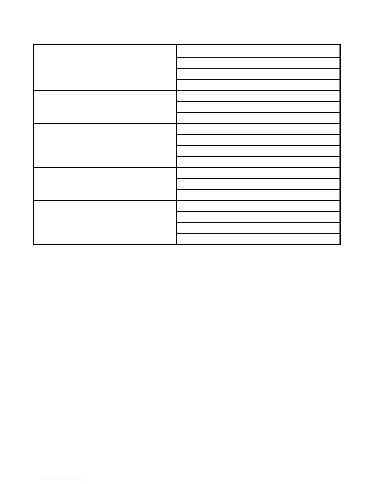
5-5. TROUBLESHOOTING
LOW OIL PRESSURE
NO OIL PRESSURE
COMPRESSOR WILL NOT ENGAGE
COMPRESSOR ENGAGES BUT WILL NOT
PRESSURIZE TANK
COMPRESSOR DOES NOT RECOVER PRESSURE
AS FAST AS IT SHOULD
LOW OIL LEVEL
LOOSE PIPE PLUG ON OIL PUMP COVER
WORN OR DEFECTIVE OIL PUMP
CRACK OR SCRATCH ON OIL PUMP COVER
DEFECTIVE OIL PUMP
BLOCKED OIL PASSAGE
DAMAGED OIL PUMP DRIVE PIN
NO POWER SUPPLIED TO COMPRESSOR
INTERNAL CIRCUIT BREAKER TRIPPED
PTO SWITCH NOT ENGAGED
DEFECTIVE PRESSURE SWITCH OR UNDERHOOD SWITCH
COMPRESSOR RELIEF V ALVE ENGAGED
AIR LEAK IN PLUMBING
WORN PISTON RINGS OR VALVE PLATES
DEFECTIVE CHECK VALVE / VALVES
DIRTY FILTER
AIR LEAK IN PLUMBING
WORN VALVE PLATES OR PISTON RINGS
FIGURE E-5. TROUBLESHOOTING CHART
Page 37
DA435HA: 99901219: 6-919980930
Page 38

DA435HA: 99901219: 6-1020020328
This parts manual is provided to the user to assist in servicing the equipment. It is the propertyof Iowa Mold Tooling Co., Inc and, as such,
may not be reproduced either whole or in part,whether by chemical, electrostatic, mechanical or photographic means without the
expressedwritten permission of an officer of Iowa Mold Tooling Co., Inc. One manual is provided with each piece of new equipment and
additional manuals may be obtained at a nominal price.
IOWA MOLD TOOLING CO., INC.
BOX 189, GARNER, IA 50438-0189
TEL: 641-923-3711
TECHNICAL SUPPORT FAX: 641-923-2424
 Loading...