

Diamond DA 40 Flight Manual

Introduction DA 40 AFM
FOREWORD
We congratulate you on the acquisition of your new DIAMOND STAR.
Skillful operation of an airplane increases both safety and the enjoyment of flying. Please
take the time therefore, to familiarize yourself with your new DIAMOND STAR.
This airplane may only be operated in accordance with the procedures and operating
limitations of this Airplane Flight Manual.
Before this airplane is operated for the first time, the pilot must familiarize himself with
the complete contents of this Airplane Flight Manual.
In the event that you have obtained your DIAMOND STAR second-hand, please let us
know your address, so that we can supply you with the publications necessary for the
safe operation of your airplane.
This document is protected by copyright. All associated rights, in particular those of
translation, reprinting, radio transmission, reproduction by photo-mechanical or similar
means and storing in data processing facilities, in whole or part, are reserved.
Copyright © by: DIAMOND AIRCRAFT INDUSTRIES GMBH
N.A. Otto-Strasse 5
A-2700 Wiener Neustadt, Austria
Phone. : +43-2622-26700
Fax : +43-2622-26780
E-Mail : office@diamond-air.at
Page 0 - 0 Revision 6 15-Sep-2004 Doc. # 6.01.01-E
DA 40 AFM Introduction
0.1 APPROVAL%
The content of approved chapters is approved by EASA. All other content is approved%
by DAI under the authority of EASA DOA No. EASA.21J.052 in accordance with Part 21.%
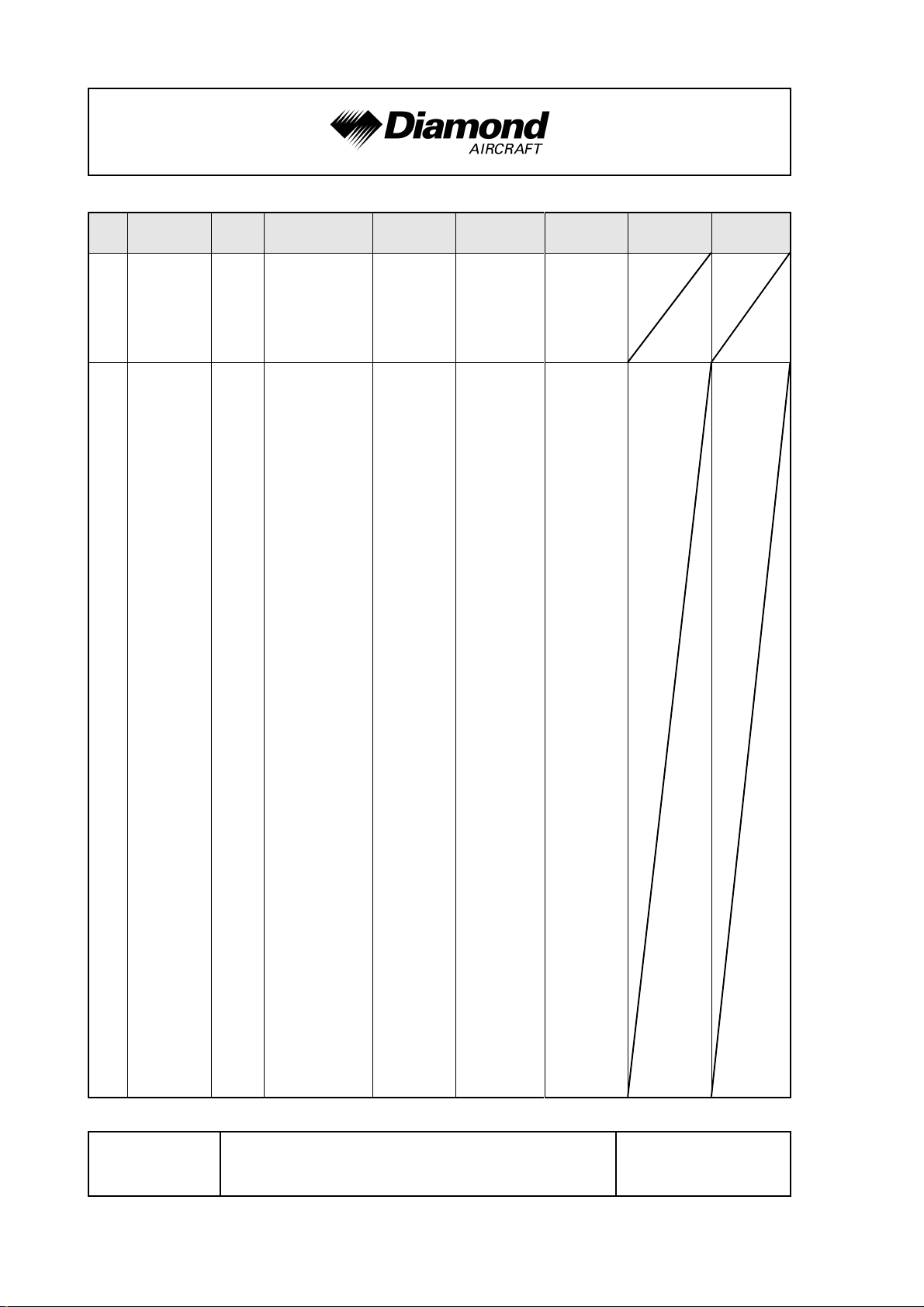
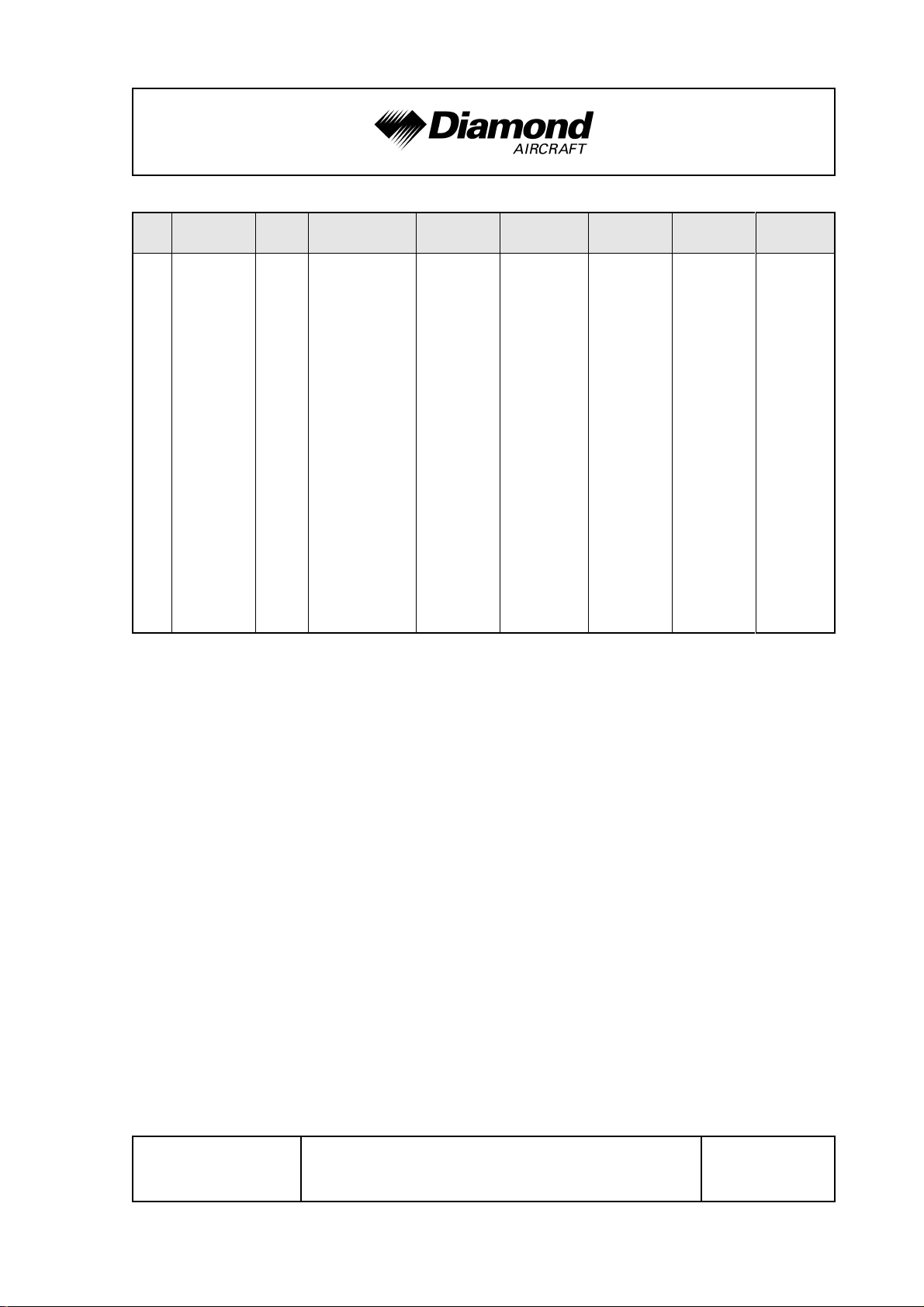
0.2 RECORD OF REVISIONS
All revisions of this manual, with the exception of -
C Temporary Revisions,
C updates of the modification level (Section 1.1),
C updated mass and balance information (Section 6.3),
C updates of the Equipment Inventory (Section 6.5), and
C updates of the List of Supplements (Section 9.2)
must be recorded in the following table. %
The new or amended text is indicated by a vertical black line at the left hand side of the
revised page, with the revision number and date appearing at the bottom of the page.
NOTE
If pages are revised which contain information valid for your
particular serial number (modification level of the airplane,
weighing data, Equipment Inventory, List of Supplements),
then this information must be transferred to the new pages
in hand-writing.
Temporary Revisions, if applicable, are inserted into this manual. Temporary Revisions
are used to provide information on systems or equipment until the next 'permanent'
Revision of the Airplane Flight Manual. When a 'permanent' Revision covers a Mandatory
or Optional Design Change Advisory (MÄM or OÄM), then the corresponding Temporary
Revision is superseded. For example: Revision 5 covers OÄM-40-061, therefore the
Temporary Revision TR-OÄM-40-061 is superseded by the 'permanent' Revision 5.
Doc. # 6.01.01-E Rev. 8 01-Dec-2010 Page 0 - 1
Introduction DA 40 AFM
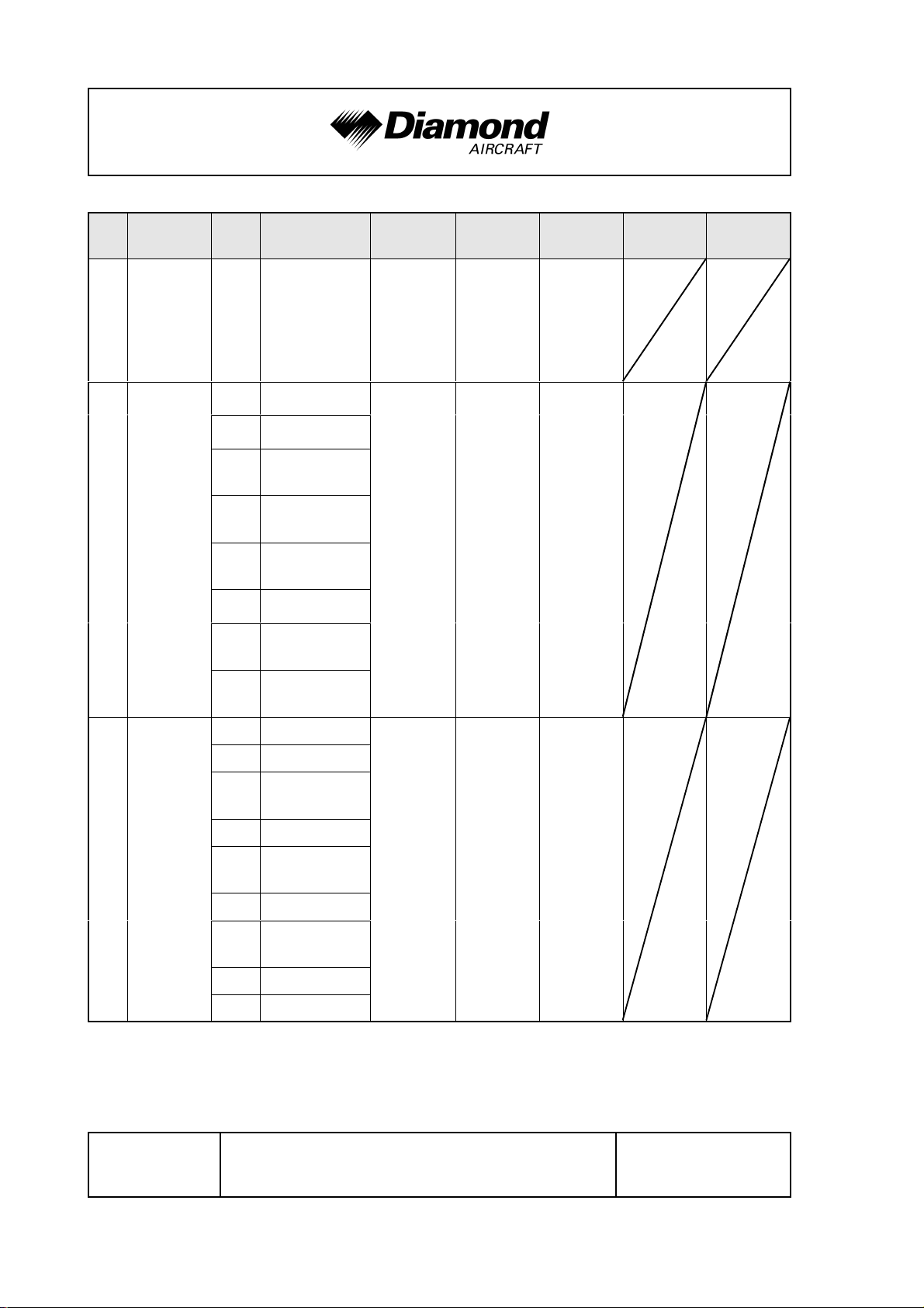
Rev.
No.
Reason
1 corrections all all 26-Sep-2000
OÄM 40-060
(White Wire
optional)
OÄM 40-068
(Essential Bus)
2
OÄM 40-073
(LASAR
optional)
corrections
Chapte
r
0 0-2, 0-4 thru 0-7
11-16
2
3
4A
4B 4B-4 thru 4B-6
6
7
0 0-2 thru 0-7
Page(s)
2-1, 2-7 thru 2-9,
2-13 thru 2-19
3-7, 3-8, 3-19,
3-20, 3-25, 3-26
4A-3 thru 4A-8,
4A-14, 4A-15
6-1, 6-2,
6-12 thru 6-14
7-1, 7-8, 7-14,
7-28 thru 7-38
Date of
Revision
19-Dec-2000
Approval
[approved by
Ing. Andreas
Winkler for
ACG]
approved by
Ing. Andreas
Winkler for
ACG]
Date of
Approval
09-Oct-2000
25-Jan-2001
Date Inserted Signature
11-2
2-1, 2-8, 2-9, 2-12,
2
2-15 thru 2-20
3 3-1, 3-25 thru 3-27
4A
5 5-7, 5-14, 5-16
6
7 7-32, 7-35, 7-36
8 8-1 thru 8-9
4A-1,
4A-8 thru 4A-31
6-7, 6-9,
6-12 thru 6-14
05-Feb-2001
[approved by
Ing. Andreas
Winkler for
ACG]
02 Jul 2001
3
OÄM 40-064
(Night VFR)
OÄM 40-069
(control surf.
gust lock)
OÄM 40-070
(tow bar)
corrections
Page 0 - 2 Rev. 8 01-Dec-2010 Doc. # 6.01.01-E
DA 40 AFM Introduction
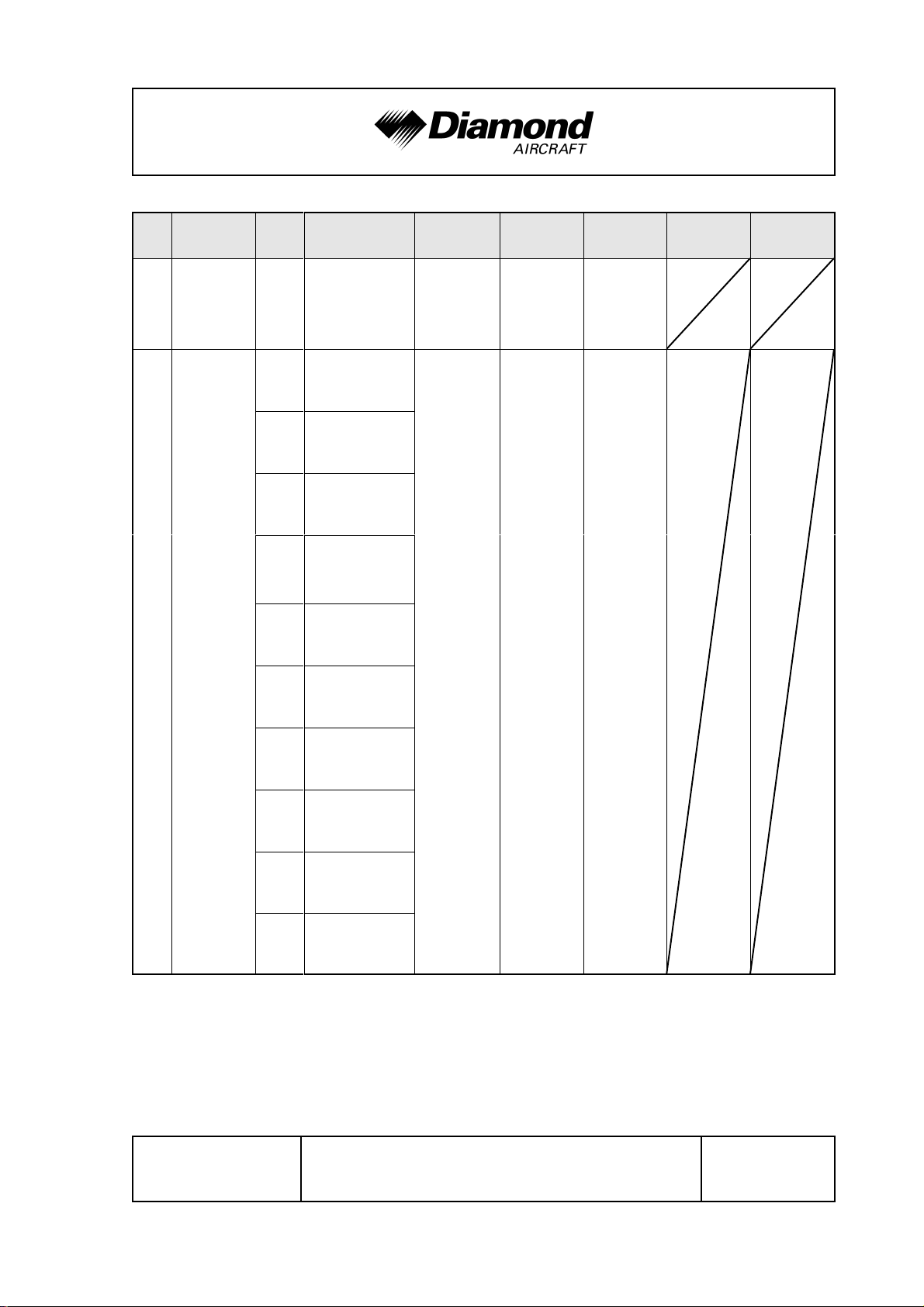
Rev.
No.
4
5
Reason
OÄM 40-067
(IFR)
corrections
OÄM 40-061
(KAP 140
autopilot)
OÄM 40-073
(SlickSTART)
OÄM 40-081
(door lock)
OÄM 40-085
(KX 155A
as COM 1)
OÄM's 40-092
thru 40-094
(Mikrotechna
ASI, altimeter,
VSI)
Chapte
r
all all 09 Apr 2001
0 0-1 thru 0-8
1 1-2, 1-5, 1-14
2
3
4A
4B 4B-1, 4B-8
6 6-5, 6-8 thru 6-17
Page(s)
2-1, 2-16, 2-22,
2-23, 2-24
3-13, 3-18, 3-22,
3-23, 3-24, 3-31,
3-36
4A-8, 4A-10, 4A-22,
4A-23, 4A-26
Date of
Revision
09 Sep 2001
Approval
[approved by
Ing. Andreas
Winkler for
ACG]
[approved by
Ing. Andreas
Winkler for
ACG]
Date of
Approval
02 Jul 2001
09 Sep 2001
Date Inserted Signature
MÄM 40-039/a
(VM 1000)
MÄM 40-048
(RH emerg.
window)
corrections
7-13, 7-14, 7-33,
7
88-10
9 9-3, 9-4, 9-5
7-35
Doc. # 6.01.01-E Rev. 8 01-Dec-2010 Page 0 - 3
Introduction DA 40 AFM
Rev.
No.
%
Reason Chapter Page(s)
type certifi-
6
cation in China
MÄM-40-
-047, -069,
-075, -078,
-096, -099,
-123e, -133,
-141, -174,
OÄM-40-
-063/b, -071/c,
-077, -078,
-080, -083/a,
-090, -091,
-097, -098,
-103, -104,
-105, -106,
-111, -112,
-114, -115,
-117, -117/a,
7
-119, -120,
-121, -122,
-124, -127,
-128, -138,
-140, -154,
-165, -167,
-168, -179,
-181, -183,
-185, -186,
-190, -198,
-200, -206,
-237, 250/a;
-175;
0 0-0, 0-5, 0-6 15 Sep 2004 2004-12326
all
all except cover
page
Date of
Revision
15 Jul 2006
EASA Approv-
al No.
Revision No. 7
of the AFM %
Doc. No.%
6.01.01-E is%
approved%
under the%
authority of%
DOA No.%
EASA.21J.052 %
ACG
Compliance
[Ing. Andreas
Winkler for
ACG]
[11 Aug 2006
Dipl.-Ing.
(FH)
Manfred
Reichel
for DAI]
Date
Inserted
Signature
RÄM-40-
-014;
corrections;
double-sided
layout
Page 0 - 4 Rev. 8 01-Dec-2010 Doc. # 6.01.01-E
DA 40 AFM Introduction
Rev.
No.
Reason Chapter Page(s)
MÄM-40-%
-176, -227/a,%
-313, -344,%
-360/a, -378,%
-401, -415,%
-428, -446;%
%
OÄM-40-%
-217, -251,%
8%
%%%
-253/b, 258,%
-267, -277/a,%
-279, 283/a,%
-284, -289,%
-326, -327;%
all except cover%
all%
page%
Date of
Revision
01 Dec 2010%
EASA Approv-
al No.
Revision No. 8%
of the AFM%
Doc. No.%
6.01.01-E is%
approved%
under the%
authority of%
DOA No.%
EASA.21J.052%
ACG
Compliance
Date
Inserted
Signature
%
corrections%
%
Doc. # 6.01.01-E Rev. 8 01-Dec-2010 Page 0 - 5
Introduction DA 40 AFM
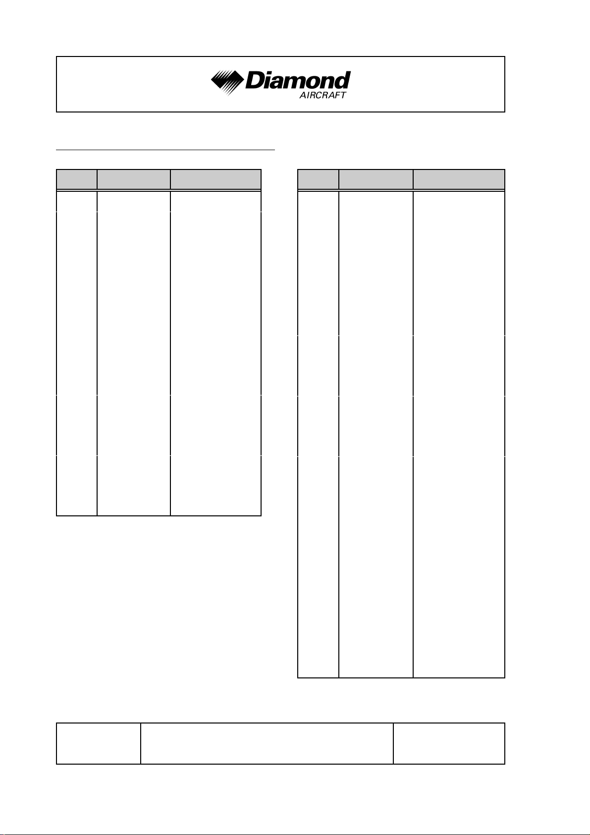
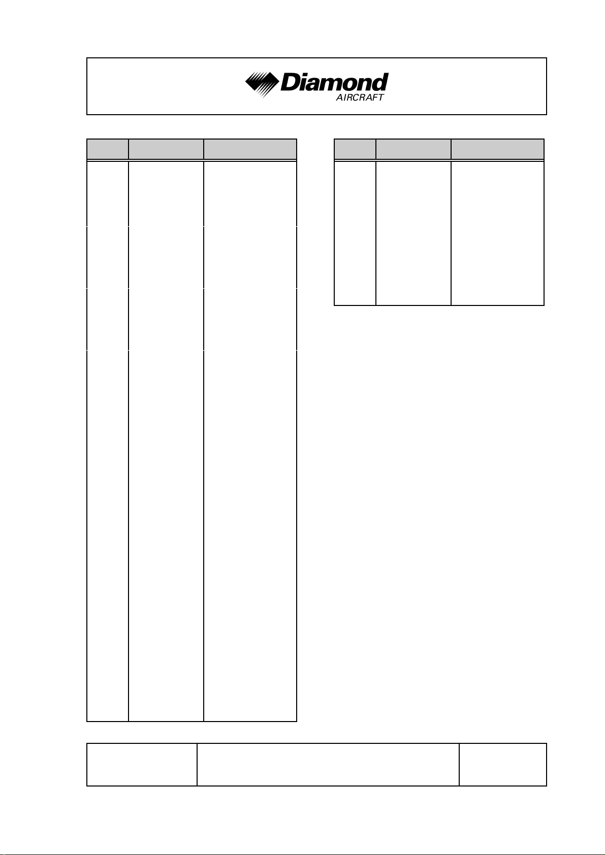
0.3 LIST OF EFFECTIVE PAGES
Ch. Page Date
0 0-0 15-Sep-2004
0-0a 15-Sep-2004
0-1 01-Dec-2010
0-2 01-Dec-2010
0-3 01-Dec-2010
0-4 01-Dec-2010
0-5 01-Dec-2010
0-6 01-Dec-2010
0-7 01-Dec-2010
0-8 01-Dec-2010
0-9 01-Dec-2010
0-10 01-Dec-2010
0-11 01-Dec-2010
0-12 01-Dec-2010
Ch. Page Date
1 1-1 01-Dec-2010
1-2 01-Dec-2010
1-3 01-Dec-2010
1-4 01-Dec-2010
1-5 01-Dec-2010
1-6 01-Dec-2010
1-7 01-Dec-2010
1-8 01-Dec-2010
1-9 01-Dec-2010
1-10 01-Dec-2010
1-11 01-Dec-2010
1-12 01-Dec-2010
1-13 01-Dec-2010
1-14 01-Dec-2010
0-13 01-Dec-2010
0-14 01-Dec-2010
1-15 01-Dec-2010
1-16 01-Dec-2010
1-17 01-Dec-2010
1-18 01-Dec-2010
1-19 01-Dec-2010
1-20 01-Dec-2010
1-21 01-Dec-2010
1-22 01-Dec-2010
1-23 01-Dec-2010
1-24 01-Dec-2010
Page 0 - 6 Rev. 8 01-Dec-2010 Doc. # 6.01.01-E
DA 40 AFM Introduction
Ch. Page Date
2 appr. 2-1 01-Dec-2010
appr. 2-2 01-Dec-2010
appr. 2-3 01-Dec-2010
appr. 2-4 01-Dec-2010
appr. 2-5 01-Dec-2010
appr. 2-6 01-Dec-2010
appr. 2-7 01-Dec-2010
appr. 2-8 01-Dec-2010
appr. 2-9 01-Dec-2010
appr. 2-10 01-Dec-2010
appr. 2-11 01-Dec-2010
appr. 2-12 01-Dec-2010
appr. 2-13 01-Dec-2010
appr. 2-14 01-Dec-2010
Ch. Page Date
2 appr. 2-28 01-Dec-2010
appr. 2-29 01-Dec-2010
appr. 2-30 01-Dec-2010
appr. 2-31 01-Dec-2010
appr. 2-32 01-Dec-2010
appr. 2-33 01-Dec-2010
appr. 2-34 01-Dec-2010
appr. 2-15 01-Dec-2010
appr. 2-16 01-Dec-2010
appr. 2-17 01-Dec-2010
appr. 2-18 01-Dec-2010
appr. 2-19 01-Dec-2010
appr. 2-20 01-Dec-2010
appr. 2-21 01-Dec-2010
appr. 2-22 01-Dec-2010
appr. 2-23 01-Dec-2010
appr. 2-24 01-Dec-2010
appr. 2-25 01-Dec-2010
appr. 2-26 01-Dec-2010
appr. 2-27 01-Dec-2010
Doc. # 6.01.01-E Rev. 8 01-Dec-2010 Page 0 - 7
Introduction DA 40 AFM
Ch. Page Date
3 3-1 01-Dec-2010
3-2 01-Dec-2010
3-3 01-Dec-2010
3-4 01-Dec-2010
3-5 01-Dec-2010
3-6 01-Dec-2010
3-7 01-Dec-2010
3-8 01-Dec-2010
3-9 01-Dec-2010
3-10 01-Dec-2010
3-11 01-Dec-2010
3-12 01-Dec-2010
3-13 01-Dec-2010
3-14 01-Dec-2010
Ch. Page Date
3 3-29 01-Dec-2010
3-30 01-Dec-2010
3-31 01-Dec-2010
3-32 01-Dec-2010
3-33 01-Dec-2010
3-34 01-Dec-2010
3-35 01-Dec-2010
3-36 01-Dec-2010
3-37 01-Dec-2010
3-38 01-Dec-2010
3-39 01-Dec-2010
3-40 01-Dec-2010
3-41 01-Dec-2010
3-42 01-Dec-2010
3-15 01-Dec-2010
3-16 01-Dec-2010
3-17 01-Dec-2010
3-18 01-Dec-2010
3-19 01-Dec-2010
3-20 01-Dec-2010
3-21 01-Dec-2010
3-22 01-Dec-2010
3-23 01-Dec-2010
3-24 01-Dec-2010
3-25 01-Dec-2010
3-26 01-Dec-2010
3-27 01-Dec-2010
3-28 01-Dec-2010
Page 0 - 8 Rev. 8 01-Dec-2010 Doc. # 6.01.01-E
DA 40 AFM Introduction
Ch. Page Date
4A 4A-1 01-Dec-2010
4A-2 01-Dec-2010
4A-3 01-Dec-2010
4A-4 01-Dec-2010
4A-5 01-Dec-2010
4A-6 01-Dec-2010
4A-7 01-Dec-2010
4A-8 01-Dec-2010
4A-9 01-Dec-2010
4A-10 01-Dec-2010
4A-11 01-Dec-2010
4A-12 01-Dec-2010
4A-13 01-Dec-2010
4A-14 01-Dec-2010
Ch. Page Date
4A 4A-28 01-Dec-2010
4A-29 01-Dec-2010
4A-30 01-Dec-2010
4A-31 01-Dec-2010
4A-32 01-Dec-2010
4A-33 01-Dec-2010
4A-34 01-Dec-2010
4A-35 01-Dec-2010
4A-36 01-Dec-2010
4A-37 01-Dec-2010
4A-38 01-Dec-2010
4A-39 01-Dec-2010
4A-40 01-Dec-2010
4A-15 01-Dec-2010
4A-16 01-Dec-2010
4A-17 01-Dec-2010
4A-18 01-Dec-2010
4A-19 01-Dec-2010
4A-20 01-Dec-2010
4A-21 01-Dec-2010
4A-22 01-Dec-2010
4A-23 01-Dec-2010
4A-24 01-Dec-2010
4A-25 01-Dec-2010
4A-26 01-Dec-2010
4A-27 01-Dec-2010
Doc. # 6.01.01-E Rev. 8 01-Dec-2010 Page 0 - 9
Introduction DA 40 AFM
Ch. Page Date
4B 4B-1 01-Dec-2010
4B-2 01-Dec-2010
4B-3 01-Dec-2010
4B-4 01-Dec-2010
4B-5 01-Dec-2010
4B-6 01-Dec-2010
4B-7 01-Dec-2010
4B-8 01-Dec-2010
4B-9 01-Dec-2010
4B-10 01-Dec-2010
4B-11 01-Dec-2010
4B-12 01-Dec-2010
Ch. Page Date
5 5-1 01-Dec-2010
5-2 01-Dec-2010
5-3 01-Dec-2010
5-4 01-Dec-2010
5-5 01-Dec-2010
5-6 01-Dec-2010
5-7 01-Dec-2010
5-8 01-Dec-2010
5-9 01-Dec-2010
5-10 01-Dec-2010
5-11 01-Dec-2010
5-12 01-Dec-2010
5-13 01-Dec-2010
5-14 01-Dec-2010
5-15 01-Dec-2010
5-16 01-Dec-2010
5-17 01-Dec-2010
5-18 01-Dec-2010
5-19 01-Dec-2010
5-20 01-Dec-2010
5-21 01-Dec-2010
5-22 01-Dec-2010
5-23 01-Dec-2010
5-24 01-Dec-2010
Page 0 - 10 Rev. 8 01-Dec-2010 Doc. # 6.01.01-E
DA 40 AFM Introduction
Ch. Page Date
6 6-1 01-Dec-2010
6-2 01-Dec-2010
6-3 01-Dec-2010
6-4 01-Dec-2010
6-5 01-Dec-2010
6-6 01-Dec-2010
6-7 01-Dec-2010
6-8 01-Dec-2010
6-9 01-Dec-2010
6-10 01-Dec-2010
6-11 01-Dec-2010
6-12 01-Dec-2010
6-13 01-Dec-2010
6-14 01-Dec-2010
Ch. Page Date
6 6-28 01-Dec-2010
6-29 01-Dec-2010
6-30 01-Dec-2010
6-31 01-Dec-2010
6-32 01-Dec-2010
6-15 01-Dec-2010
6-16 01-Dec-2010
6-17 01-Dec-2010
6-18 01-Dec-2010
6-19 01-Dec-2010
6-20 01-Dec-2010
6-21 01-Dec-2010
6-22 01-Dec-2010
6-23 01-Dec-2010
6-24 01-Dec-2010
6-25 01-Dec-2010
6-26 01-Dec-2010
6-27 01-Dec-2010
Doc. # 6.01.01-E Rev. 8 01-Dec-2010 Page 0 - 11
Introduction DA 40 AFM
Ch. Page Date
7 7-1 01-Dec-2010
7-2 01-Dec-2010
7-3 01-Dec-2010
7-4 01-Dec-2010
7-5 01-Dec-2010
7-6 01-Dec-2010
7-7 01-Dec-2010
7-8 01-Dec-2010
7-9 01-Dec-2010
7-10 01-Dec-2010
7-11 01-Dec-2010
7-12 01-Dec-2010
7-13 01-Dec-2010
7-14 01-Dec-2010
Ch. Page Date
7 7-28 01-Dec-2010
7-29 01-Dec-2010
7-30 01-Dec-2010
7-31 01-Dec-2010
7-32 01-Dec-2010
7-33 01-Dec-2010
7-34 01-Dec-2010
7-35 01-Dec-2010
7-36 01-Dec-2010
7-37 01-Dec-2010
7-38 01-Dec-2010
7-39 01-Dec-2010
7-40 01-Dec-2010
7-41 01-Dec-2010
7-15 01-Dec-2010
7-16 01-Dec-2010
7-17 01-Dec-2010
7-18 01-Dec-2010
7-19 01-Dec-2010
7-20 01-Dec-2010
7-21 01-Dec-2010
7-22 01-Dec-2010
7-23 01-Dec-2010
7-24 01-Dec-2010
7-25 01-Dec-2010
7-26 01-Dec-2010
7-27 01-Dec-2010
7-42 01-Dec-2010
7-43 01-Dec-2010
7-44 01-Dec-2010
7-45 01-Dec-2010
7-46 01-Dec-2010
7-47 01-Dec-2010
7-48 01-Dec-2010
7-49 01-Dec-2010
7-50 01-Dec-2010
7-51 01-Dec-2010
7-52 01-Dec-2010
7-53 01-Dec-2010
7-54 01-Dec-2010
Page 0 - 12 Rev. 8 01-Dec-2010 Doc. # 6.01.01-E

DA 40 AFM Introduction
Ch. Page Date
7 7-55 01-Dec-2010
7-56 01-Dec-2010
7-57 01-Dec-2010
7-58 01-Dec-2010
Ch. Page Date
8 8-1 01-Dec-2010
8-2 01-Dec-2010
8-3 01-Dec-2010
8-4 01-Dec-2010
8-5 01-Dec-2010
8-6 01-Dec-2010
8-7 01-Dec-2010
8-8 01-Dec-2010
Ch. Page Date
9 9-1 01-Dec-2010
9-2 01-Dec-2010
9-3 01-Dec-2010
9-4 01-Dec-2010
9-5 01-Dec-2010
9-6 01-Dec-2010
8-9 01-Dec-2010
8-10 01-Dec-2010
8-11 01-Dec-2010
8-12 01-Dec-2010
Doc. # 6.01.01-E Rev. 8 01-Dec-2010 Page 0 - 13

Introduction DA 40 AFM
0.4 TABLE OF CONTENTS
Chapter
GENERAL
(a non-approved chapter) ....................................... 1
OPERATING LIMITATIONS
(an approved chapter) .......................................... 2
EMERGENCY PROCEDURES
(a non-approved chapter) ....................................... 3
NORMAL OPERATING PROCEDURES
(a non-approved chapter) ......................................4A
ABNORMAL OPERATING PROCEDURES
(a non-approved chapter) ......................................4B
PERFORMANCE
(a non-approved chapter) ....................................... 5
MASS AND BALANCE / EQUIPMENT LIST
(a non-approved chapter) ....................................... 6
DESCRIPTION OF THE AIRPLANE AND ITS SYSTEMS
(a non-approved chapter) ....................................... 7
AIRPLANE HANDLING, CARE AND MAINTENANCE
(a non-approved chapter) ....................................... 8
SUPPLEMENTS .................................................... 9
Page 0 - 14 Rev. 8 01-Dec-2010 Doc. # 6.01.01-E

DA 40 AFM General
CHAPTER 1
GENERAL
Page
1.1 INTRODUCTION .......................................1-2
1.2 CERTIFICATION BASIS ..................................1-5
1.3 WARNINGS, CAUTIONS AND NOTES ......................1-5
1.4 DIMENSIONS..........................................1-6
1.5 DEFINITIONS AND ABBREVIATIONS .......................1-8
1.6 UNITS OF MEASUREMENT .............................1-18
1.6.1 CONVERSION FACTORS ..........................1-18
1.6.2 CONVERSION CHART LITERS / US GALLONS.........1-20
1.7 THREE-VIEW DRAWING................................1-21
1.8 SOURCE DOCUMENTATION ............................1-22
1.8.1 ENGINE ........................................1-22
1.8.2 PROPELLER ....................................1-23
1.8.3 ENGINE INSTRUMENTS ...........................1-23
1.8.4 IGNITION CONTROL UNIT .........................1-24
Doc. # 6.01.01-E Rev. 8 01-Dec-2010 Page 1 - 1
General DA 40 AFM
1.1 INTRODUCTION
This Airplane Flight Manual has been prepared in order to provide pilots and instructors
with all the information required for the safe and efficient operation of the airplane.
The Airplane Flight Manual includes all the data which must be made available to the pilot
according to the JAR-23 requirement. Beyond this, it contains further data and operating
instructions which, in the manufacturer’s opinion, could be of value to the pilot.
This Airplane Flight Manual is valid for all serial numbers. Equipment and modification
level (design details) of the airplane may vary from serial number to serial number.
Therefore, some of the information contained in this manual is applicable depending on
the respective equipment and modification level. The exact equipment of your serial
number is recorded in the Equipment Inventory in Section 6.5. The modification level is
recorded in the following table (as far as necessary for this manual).
Modification Source Installed
RH Emergency Window MÄM 40-048 9 yes 9 no
Modified MLG Strut MÄM 40-123/e 9 yes 9 no
1200 kg Maximum Take-Off Mass% MÄM 40-227% 9 yes% 9 no%
Autopilot OÄM 40-061 9 yes 9 no
Tow-Plane Operation OÄM 40-063/b 9 yes 9 no
Emergency Switch OÄM 40-067 9 yes 9 no
Essential Bus OÄM 40-068 9 yes 9 no
Long Range Tank OÄM 40-071/b 9 yes 9 no
Alternate Static Valve OÄM 40-072 9 yes 9 no
SlickSTART Ignition System OÄM 40-073 9 yes 9 no
MT P-420-10 Governor
% OÄM 40-077% 9 yes% 9 no%
Operation with Winter Kit OÄM 40-078 9 yes 9 no
Page 1 - 2 Rev. 8 01-Dec-2010 Doc. # 6.01.01-E
DA 40 AFM General
Modification Source Installed
Door Locking System OÄM 40-081 9 yes 9 no
NLG Speedkit OÄM 40-105 9 yes 9 no
MLG Speedkit OÄM 40-106 9 yes 9 no
Essential Tie Relay Bypass OÄM 40-126 9 yes 9 no
Baggage Extension
Baggage Tray*
Winter Baffle Fresh Air Inlet OÄM 40-183 9 yes 9 no
Nose Landing Gear Tie-Down OÄM 40-200 9 yes 9 no
Electrical Rudder Pedal Adjustment% OÄM 40-251% 9 yes% 9 no%
CO Monitor% OÄM 40-253% 9 yes% 9 no%
Autopilot Static Source% OÄM 40-267% 9 yes% 9 no%
Tall Main Landing Gear% OÄM 40-283% 9 yes% 9 no%
ELT Artex ME 406 ‘ACE’% OÄM 40-284% 9 yes% 9 no%
MT P-860-23 Governor% OÄM 40-289% 9 yes% 9 no%
Emergency Axe% OÄM 40-326% 9 yes% 9 no%
*For installation of the Baggage Tray the Baggage Extension must be installed.
This Airplane Flight Manual must be kept on board the airplane at all times. Its designated
OÄM 40-163
OÄM 40-164
9 yes
9 yes
9 no
9 no
place is the side bag of the forward left seat.
This Airplane Flight Manual constitutes an FAA Approved Airplane Flight Manual for
US registered airplanes in accordance with FAA regulation 14 CFR, Part 21.29.
Doc. # 6.01.01-E Rev. 8 01-Dec-2010 Page 1 - 3

General DA 40 AFM
CAUTION
The DA 40 is a single engine airplane. When the operating
limitations and maintenance requirements are complied with,
it has the high degree of reliability which is required by the
certification basis. Nevertheless, an engine failure is not
completely impossible. For this reason, flights during the
night, on top, under instrument meteorological conditions
(IMC), or above terrain which is unsuitable for a landing,
constitute a risk. It is therefore highly recommended to select
flight times and flight routes such that this risk is minimized.
Page 1 - 4 Rev. 8 01-Dec-2010 Doc. # 6.01.01-E
DA 40 AFM General
1.2 CERTIFICATION BASIS
This airplane has been type certified in accordance with the JAA JC/VP procedure. The
certification basis is JAR-23, published on 11-Mar-1994.
1.3 WARNINGS, CAUTIONS AND NOTES
Special statements in the Airplane Flight Manual concerning the safety or operation of
the airplane are highlighted by being prefixed by one of the following terms:
WARNING
means that the non-observation of the corresponding
procedure leads to an immediate or important degradation
in flight safety.
CAUTION
means that the non-observation of the corresponding
procedure leads to a minor or to a more or less long term
degradation in flight safety.
NOTE
draws the attention to any special item not directly related to
safety but which is important or unusual.
Doc. # 6.01.01-E Rev. 8 01-Dec-2010 Page 1 - 5

General DA 40 AFM
1.4 DIMENSIONS
Overall Dimensions
Span : appr. 11.94 m appr. 39 ft 2 in
Length : appr. 8.01 m appr. 26 ft 3 in
Height : appr. 1.97 m appr. 6 ft 6 in
Wing
Airfoil : Wortmann FX 63-137/20 - W4
Wing Area : appr. 13.54 m² appr. 145.7 sq.ft.
Mean aerodynamic
chord (MAC) : appr. 1.121 m appr. 3 ft 8.1 in
Aspect ratio : appr. 10.53
Dihedral : appr. 5°
Leading edge sweep : appr. 1°
Aileron
Area (total, left + right) : appr. 0.654 m² appr. 7.0 sq.ft.
Wing Flaps
Area (total, left + right) : appr. 1.56 m² appr. 16.8 sq.ft.
Horizontal Tail
Area : appr. 2.34 m
2
appr. 25.2 sq.ft.
Elevator area : appr. 0.665 m² appr. 7.2 sq.ft.
Angle of incidence : appr. -3.0° relative to longitudinal axis of airplane
Page 1 - 6 Rev. 8 01-Dec-2010 Doc. # 6.01.01-E

DA 40 AFM General
Vertical Tail
Area : appr. 1.60 m² appr. 17.2 sq.ft.
Rudder area : appr. 0.47 m² appr. 5.1 sq.ft.
Landing Gear
Track : appr. 2.97 m appr. 9 ft 9 in
Wheelbase : appr. 1.68 m appr. 5 ft 6 in
Nose wheel : 5.00-5; 6 PR, 120 mph
Main wheel : (a) 6.00-6; 6 PR, 120 mph%
in combination with any MLG strut%
(b) 15 x 6.0-6; 6 PR, 160 mph%
only in combination with the "thin"%
(MÄM 40-123/e) or the "tall" (OÄM 40-283)%
MLG strut%
Doc. # 6.01.01-E Rev. 8 01-Dec-2010 Page 1 - 7

General DA 40 AFM
1.5 DEFINITIONS AND ABBREVIATIONS
(a) Airspeeds
CAS: Calibrated Airspeed. Indicated airspeed, corrected for installation and
instrument errors. CAS equals TAS at standard atmospheric conditions at MSL.
IAS: Indicated Airspeed as shown on an airspeed indicator.
KCAS: CAS in knots.
KIAS: IAS in knots.
TAS: True Airspeed. The speed of the airpl ane relative to the air. TAS is CAS
corrected for errors due to altitude and temperature.
vA: Maneuvering Speed. Full or abrupt control surface movement is not permissible
above this speed.
vFE: Max. Flaps Extended Speed. This speed must not be exceeded with the given
flap setting.
vNE: Never Exceed Speed in smooth air. This speed must not be exceeded in any
operation.
v
NO
Maximum Structural Cruising Speed. This speed may be exceeded only in
smooth air, and then only with caution.
vS: Stalling Speed, or the minimum continuous speed at which the airplane is still
controllable in the given configuration.
v
: Stalling Speed, or the minimum continuous speed at which the airplane is still
S0
controllable in the landing configuration.
vx: Best Angle-of-Climb Speed.
vy: Best Rate-of-Climb Speed.
Page 1 - 8 Rev. 8 01-Dec-2010 Doc. # 6.01.01-E

DA 40 AFM General
(b) Meteorological Terms
ISA: International Standard Atmosphere. Conditions at which air is
identified as an ideal dry gas. The temperature at mean sea level is
15 EC (59 °F), air pressure at MSL is 1013.25 hPa (29.92 inHg); the
temperature gradient up to the altitude at which the temperature
reaches -56.5 EC (-69.7 °F) is -0.0065 EC/m (-0.00357 °F/ft), and
above this 0 EC/m (0 °F/ft).
MSL: Mean Sea Level.
OAT: Outside Air Temperature.
QNH: Theoretical atmospheric pressure at MSL, calculated from the
elevation of the measuring point above MSL and the actual
atmospheric pressure at the measuring point.
Indicated Pressure Altitude:
Altitude reading with altimeter set to 1013.25 hPa (29.92 inHg).
Pressure Altitude: Altitude above MSL, indicated by a barometric altimeter which is set
to 1013.25 hPa (29.92 inHg). The Pressure Altitude is the Indicated
Pressure Altitude corrected for installation and instrument errors.
In this Airplane Flight Manual altimeter instrument errors are regarded
as zero.
Density Altitude: Altitude in ISA conditions at which the air density is equal to the
current air density.
Wind: The wind speeds which are shown as variables in the diagrams in
this manual should be regarded as headwind or downwind
components of the measured wind.
Doc. # 6.01.01-E Rev. 8 01-Dec-2010 Page 1 - 9

General DA 40 AFM
(c) Flight Performance and Flight Planning
Demonstrated Crosswind Component:
The speed of the crosswind component at which adequate
maneuverability for take-off and landing has been demonstrated during
type certification.
MET: Weather, weather advice.
NAV: Navigation, route planning.
(d) Mass and Balance (M&B, W&B)
DP: Datum Plane; an imaginary vertical plane from which all horizontal
distances for center of gravity calculations are measured.
Moment Arm: The horizontal distance from the Datum Plane to the Center of Gravity
of a component.
Moment: The mass of a component multiplied by its moment arm.
CG: Center of Gravity, also called 'center of mass'. Imaginary point in which
the airplane mass is assumed to be concentrated for mass and balance
calculations. Its distance from the Datum Plane is equal to the Center
of Gravity Moment Arm.
Center of Gravity Moment Arm:
The Moment Arm which is obtained if one divides the sum of the individual
moments of the airplane by its total mass.
Center of Gravity Limits:
The Center of Gravity range within which the airplane, at a given mass,
must be operated.
Page 1 - 10 Rev. 8 01-Dec-2010 Doc. # 6.01.01-E
DA 40 AFM General
Usable Fuel: The quantity of fuel available for flight planning.
Unusable Fuel: The quantity of fuel remaining in the tank which cannot be used for flight.
Empty Mass: The mass of the airplane including unusable fuel, all operating
consumables and the maximum quantity of oil.
Useful Load: The difference between take-off mass and empty mass.
Maximum Take-off Mass:
The maximum permissible mass for take-off.
Maximum Landing Mass:
The highest mass for landing conditions at the maximum descent velocity.
This velocity was used in the strength calculations to determine the
landing gear loads during a particularly hard landing.
(e) Engine
Take-off Power:
Maximum permissible engine output power for take-off.
Maximum Continuous Power:
Maximum permissible engine output power used continuously during
flight.
CHT: Cylinder Head Temperature.
EGT: Exhaust Gas Temperature.
Doc. # 6.01.01-E Rev. 8 01-Dec-2010 Page 1 - 11

General DA 40 AFM
(f) Designation of the Circuit Breakers on the Instrument Panel
Asymmetric Instrument Panel (Circuit Breakers Right Hand)
AVIONICS:
ADF Automatic Direction Finder
AUDIO Audio Panel / Intercom
AUTOPILOT Autopilot
AVIONIC BUS Avionic Bus
DME Distance Measuring Equipment
ESSENTIAL AVIONIC Essential Avionic Bus
GPS Global Positioning System
GPS2 Global Positioning System #2
ENGINE:
NAV/COM1 Navigation/Communication #1
NAV/COM2 Navigation/Communication #2
STRIKE Strike Finder
XPDR Transponder
IGNITION Ignition
INST. 1 Engine Instrument VM 1000
START Starter
Page 1 - 12 Rev. 8 01-Dec-2010 Doc. # 6.01.01-E

DA 40 AFM General
LIGHTING:
FLOOD Flood Light
INST. Instrument Lights
LANDING Landing Light
POSITION Position Lights
STROBE Strobe Light (=Anti Collision Light = ACL)
TAXI/MAP Taxi Light/Map Light
SYSTEMS:
ANNUN. Annunciator Panel
DG Directional Gyro
FAN/OAT Fan/Outside Air Temperature Indicator
FLAPS Flaps
FUEL PUMP Fuel Pump
HORIZON Artificial Horizon (Attitude Gyro)
PITOT HEAT Pitot Heating System
T&B Turn & Bank Indicator
ELECTRICAL:
ALT. Alternator
ALT. CONT. Alternator Control
ALT. PROT. Alternator Protection
BATT. Battery
ESSENTIAL TIE Bus Interconnection
MAIN TIE Bus Interconnection
MASTER CONTROL Master Control (avionic master switch, essential bus
switch, essential avionics relay, bus interconnection
relay, avionics master relay)
Doc. # 6.01.01-E Rev. 8 01-Dec-2010 Page 1 - 13

General DA 40 AFM
Symmetric Instrument Panel (Circuit Breakers Bottom Side)
MAIN BUS:
ALT. Alternator
ALT. CONT. Alternator Control
ALT. PROT. Alternator Protection
AV. BUS Avionic Bus
DG Directional Gyro
FAN/OAT Fan/Outside Air Temperature Indicator
FUEL PUMP Fuel Pump
IGNITION Ignition
INST. Instrument Lights
MAIN TIE Bus Interconnection
POSITION Position Lights
START Starter
STROBE Strobe Lights (Anti Collision Lights, ACLs)
T & B Turn & Bank Indicator
TAXI/MAP Taxi Light/Map Light
Page 1 - 14 Rev. 8 01-Dec-2010 Doc. # 6.01.01-E
 Loading...