

Diamond D7401 Installation Manual
LOWPASS ON/OFF
Pushing this button “IN” engages the Lowpass filter. Pushing this button
“OUT” will bypass the filter.
LOWPASS FREQUENCY
Turning this control sets the Lowpass crossover point from 50Hz (fully
counterclockwise) to 5kHz (fully clockwise).
HIGHPASS ON/OFF
Pushing this button “IN” engages the Highpass filter. Pushing this button
“OUT” will bypass the filter.
LOWPASS
FREQUENCY
HIGHPASS FREQUENCY
Turning this control sets the Highpass crossover point from 15Hz (fully
counterclockwise) to 1.5kHz (fully clockwise).
Note: By engaging both Highpass and Lowpass filters and setting the desired
crossover points, a Bandpass filter can be created:
AUXILIARY CROSSOVER
Signal can be parallel routed from the INPUTS (X-OVER INPUT SELECT
button set to the “IN” position) or be directly sent to this crossover via the
AUX. X-OVER INPUT RCA jacks(X-OVER INPUT SELECT button set to
the “OUT” position). This configuration allows the AUX crossover to be used
with a separate stereo amplifier not equipped with its own on-board crossover
for the ultimate in system flexibility.
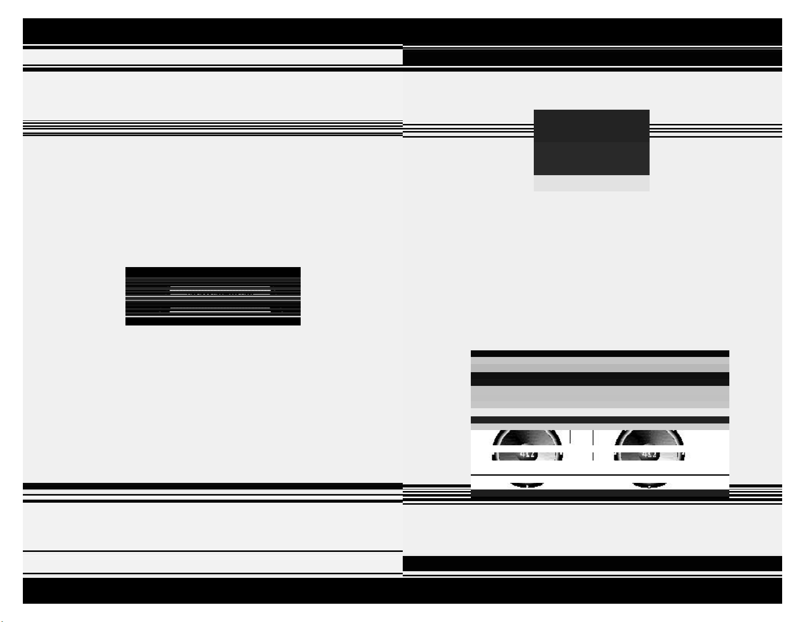
D7 CROSSOVER FREQUENCIES
Diamond Audio D7401 features fully variable crossovers. The frequency
control knobs (located in the tray on the top of the amplifier) when rotated all
the way to the left are labeled 50Hz Lowpass and 15Hz Highpass. When
rotated all the way to the right are labeled 5kHz Lowpass and 1.5kHz
Highpass.
Notice that the outer most circle of numbers (1:00, 2:00, etc.) represent
numbers as they appear on the face of a clock. The number underneath each
“hour” designation on the simulated clock face is the approximate crossover
frequency at that position.
BRIDGING
The D7401 is a mono-block (one channel) amplifier. There is no need to
“bridge” the outputs. The two sets of outputs are paralleled inside the amp for
installation convenience. This allows for a 4 Ohm load to be wired to each set
of outputs and the amp will see a 2 Ohm load. This also allows for a 2 Ohm
load to be wired to just one set of inputs (either one).
To make basic setting of the crossover frequencies a little easier, we’ve
come up with the following rotational diagram:
10
Note: It is important that a 2 Ohm minimum total speaker impedance load is
observed! If an impedance load of less than 2 Ohms is used, you will
eventually damage your amplifier and void your warranty.
11
RCA INPUTS AND OUTPUTS
As seen in the above drawing, the function of the RCA inputs, outputs,
and feature buttons are as follows:
INPUT
The RCA cables from your source unit should be inserted here.
-12dB BUTTON: INPUT
To the right of the INPUT RCAs you will find the -12dB button. Pushing this
button: “IN” allows your amplifier to accept signal voltages as high as 12VRMS.
Pushing this button “OUT” configures the amplifier to accept signal voltages up
to 6VRMS.
Note: To set crossovers, first remove the two 1/16” Allen screws holding
down the security cover using the Allen key provided. When reinstalling
the cover be careful not to overtighten the screws. Damage to the cover
may result.
SUB CROSSOVER CONTROLS
As seen in the above drawing, the function of the crossover controls (from
left to right) are as follows:
-12dB BUTTON: AUX X-OVER INPUT
Works the same as above, but for the X-OVER INPUT RCAs.
AUX X-OVER INPUT
These RCA jacks allow you independent access to the AUX X-OVER.
AUX X-OVER INPUT SELECT
This button selects the input signal used by the AUX X-OVER. Pushing this
button “IN” sends the signals from the main amp inputs to the AUX X-OVER.
Pushing the button “OUT” allows the AUX X-OVER to use signals from any
other source in your system.
AUX X-OVER OUT
These RCA outputs are used to provide filtered or unfiltered signals to an
outboard processor or amplifier.
By pushing the X-OVER INPUT SELECT button to the “IN” position,
and pushing the LOWPASS ON/OFF and HIGHPASS ON/OFF crossover
buttons to the “OUT” position, signals available at the INPUTS will bypass the
crossover and be made available at the AUX X-OVER OUTPUT RCAs allowing
you to “daisy-chain” multiple D7 amplifiers for the ultimate in
system design flexibility.
GAIN
This control matches the output voltage of the source unit or processor to the
amplifier inputs. Rotating this control to the “MIN” mark (counterclockwise)
configures your D7 amplifier to accept input voltages as high as 12V RMS with
the -12dB button pushed “IN” (see “RCA INPUT” drawing on page 12). This
control should be set as low as possible. The basic procedure for setting
input gains is as follows:
1. Adjust all amplifier gain controls to just above the minimum setting
(fully counterclockwise). If your source unit output voltage is less than
6 Volts RMS, push the –12dB button for the selected channel pair to
the “OUT” position. If the available signal voltage is more than 6 Volts
RMS, push the -12dB button to the “IN” position.
2. Using the highest quality source (usually CD) play some music and
slowly turn up the source unit until you can hear distortion. Now turn
down the volume until the distortion stops. This is your maximum
source unit level.
3. Turn up the amplifier gain until audible distortion starts. Turn down
the gain to the point JUST BELOW the start of the distortion.
4. Repeat step 3 for all amplifiers in your system.
Please refer to the Diamond Audio Level Setting Technical Brief available from
the Tech Department for a comprehensive level setting procedure.
12
9
SPEAKER WIRING
THERMAL MANAGEMENT SYSTEM
Diamond Audio recommends using speaker wire of at least 16 gauge.
Lay out the wire in the vehicle from the individual speaker locations to the
amplifier(s). Observe safe wiring precautions.
Your D7 Professional Reference Series Amplifier will accept speaker wire
up to 10 gauge directly. Locate the speaker terminal block on the end of the
amplifier. Strip approximately 1/2 inch of insulation from the wire, insert
the wire into the terminal, and tighten the Allen screw. Repeat for all speaker
wires. Please observe our recommended minimum speaker impedances to
prevent possible damage.
Banana Jacks using up to 8 gauge wire can be inserted into the speaker block.
Remove the set screw completely and insert the Banana Jack into the end of
the block.
The two sets of speaker outputs on the D7401 are paralleled inside the
amplifier for convenience in installation.
CROSSOVER SECTION
All Diamond Audio D7 amplifiers employ the most flexible internal crossover
sections currently available in mobile audio. They feature third-order 18dB/
octave Butterworth filters. These filter networks sum to a flat response at their
-3dB break points. This results in a smooth and seamless transition from one
frequency band to the next. Butterworth filters provide maximally flat
frequency responses when compared to other filter structures.
All crossover controls are mounted on the top of the amplifier. The internal
subwoofer crossover features a 18dB/octave Lowpass filter and a 18dB/octave
Subsonic filter. The Lowpass Filter is continuously variable from 50Hz to
5kHz and the Highpass from 15Hz to 1.5kHz.
The D7401 amplifier also provide a separate fully-independent crossover for
the output RCA jacks providing filter control of any other amplifier. It is
continuously variable from 50Hz to 5kHz; High, Low, Bandpass or Full Range.
When switched off, they are completely out of the signal path.
All D7 Professional Reference Series Amplifiers feature our Intelligent Thermal
Management System . All amplifiers feature one or two (depending
on model) internally mounted temperature-controlled cooling fans.
Care should be taken to allow adequate “breathing room” (approximately
2 inches) on all sides of the installed amplifier to allow the system to operate
at peak efficiency.
Cool outside air is drawn into the amplifier through the side vents on each
end panel. The air is then drawn over the top of the main circuit board, down
through the fan over the internal heat sink fins (in two directions) and out
through exhaust vents on the bottom of each end panel. In this way, the
cooling fan(s) remain nearly inaudible under almost all listening conditions.
When D7 amplifiers operate at high power for prolonged periods, the
temperature sensors instruct an intelligent monitoring circuit to speed up the
fan(s) until the amplifier has cooled down to its normal operating temperature.
Amplifier models D7401 also features our unique Power-Flow Busbar. The
shroud connecting and covering the two internal cooling fans of these amplifiers
is made of solid nickel-plated copper. Each end of this fan shroud is soldered to
full width pads on the main circuit board. The center
of this shroud is attached to the fans at eight points. The high current ground
path for the speakers now travels over the cooling fans through the shroud,
which functions as a busbar. At the same time, these high current signals are
completely isolated from the circuit board traces that carry low-level signals.
8
13
 Loading...