

Diamond CPE434 N, BRIO 43S/X N, CPE643F N, BRIO64/X N, CPE644 N Installation - Use - Maintenance
...Page 1
Mod: CGE611-NP
Production code: 503.016.201
05/2015
Page 2
1
UK
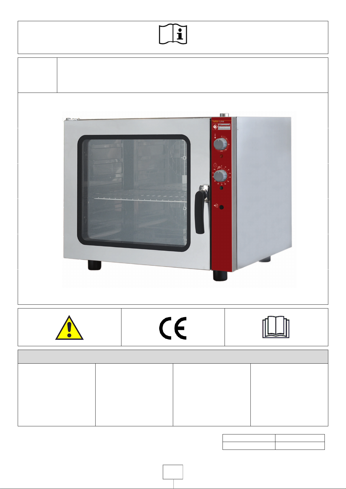
ELECTRIC FAN OVENS
Installation – Use - Maintenance
MOD.
BRIO43/X N
BRIO 43S/X N
BRIO64/X N
CPE434 N
CPE643F N
CPE644 N
CPE 644 N 230/1
CPE664 NP
GASTRO23/X N
CGE23 N
CGE11 N
CGE11 N 230/1
CGE611 NP
Doc.n° 252.386.00
Edition 07
Page 3

2
UK - INSTALLATION – USE - MAINTENANCE .............................................................................................................................. 11
I. GENERAL PRESCRIPTIONS ......................................................................................................................................................................... 11
1. DISPOSAL OF PACKING AND OF THE APPLIANCE .......................................................................................................................................................... 12
2. SAFETY AND CONTROL DEVICES ................................................................................................................................................................................... 12
II. INSTRUCTIONS FOR INSTALLATION ........................................................................................................................................................... 12
3. REMINDERS FOR THE INSTALLER .................................................................................................................................................................................. 12
4. REFERENCE STANDARDS AND LAWS ............................................................................................................................................................................ 13
5. UNPACKING .................................................................................................................................................................................................................. 13
6. POSITIONING ................................................................................................................................................................................................................ 13
7. CONNECTIONS .............................................................................................................................................................................................................. 13
8. COMMISSIONING ......................................................................................................................................................................................................... 14
III. INSTRUCTIONS FOR USE ............................................................................................................................................................................ 14
9. REMINDERS FOR THE USER .......................................................................................................................................................................................... 14
10. PROLONGED DISUSE ..................................................................................................................................................................................................... 15
IV. INSTRUCTIONS FOR CLEANING .................................................................................................................................................................. 15
11. REMINDERS FOR CLEANING ......................................................................................................................................................................................... 15
V. INSTRUCTIONS FOR MAINTENANCE .......................................................................................................................................................... 15
12. REMINDERS FOR THE MAINTENANCE TECHNICIAN ...................................................................................................................................................... 15
13. REPLACING COMPONENTS ........................................................................................................................................................................................... 15
14. MAIN COMPONENTS .................................................................................................................................................................................................... 16
PANNELLO DI CONTROLLO - CONTROL PANELS - PANNEAU DE CONTROLE – SCHALTBRETT - PANEL DE CONTROL
TAB1 - DATI TECNICI - TECHNICAL DATA - TECHNISCHE DATEN - CARACTERISTIQUES TECHNIQUES - DATOS TECNICOS- TECHNISCHE
GEGEVENS DATI TECNICI APPARECCHIATURE ELETTRICHE - DATI TECNICI ATECHNICAL DATA OF ELECTRIC APPLIANCES - CARACTÈRISTIQUES TECHNIQUES DES APPAREILS
ELECTRIQUES - TECHNISCHE DATEN ELEKTROGERATE - DATOS TÉCNICOS DE LOS EQUIPOS ELÉCTRICOS - TECHNISCHE GEGEVENS ELEKTRISCHE APPARATUUR
Page 4
11
Keep this manual in a safe place, known to all users,
This equipment is designed for cooking food. It is
This appliance is not intended for use by people
The appliance must be used by trained personn
el.
DO NOT STORE " AMMABLE MATERIALS
Identify the specific appliance model. The model
This device emits a sound pressure level less than
In the event of an appliance fault or malfunction
Use only detergents, that are suitable for oven
Do not allo
w dirt, fat, food or other residuals to
This equipment is supplied normally packed and
UK - INSTALLATION – USE - MAINTENANCE
number is detailed on the packing and on the
I.
GENERAL PRESCRIPTIONS
appliance dataplate.
READ THIS MANUAL CAREFULLY. IT
PROVIDES IMPORTANT INFORMATION
FOR SAFE INSTALLATION, USE AND
MAINTENANCE OF THE APPLIANCE.
FAILURE TO COMPLY WITH WHAT IS
PRESENTED BELOW MAY COMPROMISE
THE SAFETY OF THE EQUIPMENT.
THE MANUFACTURER WILL NOT BE
LIABLE FOR ANY DAMAGE OR INJURY
RESULTING FROM FAILURE TO
OBSERVING THE FOLLOWING RULES.
TRANSLATION OF THE ORIGINAL
INSTRUCTIONS.
so that it can be consulted throughout the working
life of the appliance.
DO NOT OBSTRUCT ANY AIR VENTS OR
DRAINS PRESENT ON THE APPLIANCE.
70 dB (A)
switch the appliance off at the main switch installed
upline.
The appliance should be frequently cleaned and
disconnected, when this occurs.
cleaning; do not use these for grills, as they are too
aggressive and rich in caustic soda.
form deposits on the appliance.
Do not clean the appliance with direct jets of water.
HANDLING AND UNPACKING
intended for industrial use. Any other use is to be
considered improper
(including children) with limited physical, sensory or
mental abilities or without experience and
knowledge of it.
Unless they are supervised or instructed in its use
by a person responsible for their safety.
Do not leave the appliance unattended when
operating.
IN CLOSE PROXIMITY TO THE
APPLIANCE. FIRE HAZARD.
The packaging shows the weight of the equipment,
volume, and signs for the transport and storage.
DETAILS OF STAFF
For handling of the equipment are not necessary
qualifications required by the personnel for the
purpose (keep in mind the kind of packaging).
It is however recommended to do so to those who
habitually uses lifting and transport.
STATE EQUIPMENT
palletized.
Page 5

12
In the case of delivery by our opinion the
equipment can also be devoid of packaging, other
The equipment can be lifted and moved with a
-
-
- Be sure to always check the equipment during
Do not stack more than the equipment packe
d
Make sure that the forks do not hit the frame of the
- the transparent cover, the bags containing the
-
APPLIANCE
The appliance is manufactured 90% from recyclable
The appliance must be scrapped in com
pliance with
The appliance is equipped with a manual reset
Identify the specific appliance model. The model
The appliance must be installed in a well
-
ventilated
types of packaging can be provided according to the
destination and / or customer requirements.
the straps (in Polypropylene - PP).
MEANS NECESSARY FOR HANDLING
forklift, crane, cranes or other appropriate means
having an adequate capacity.
Check the alignment of the forks and the stability of
the load before moving the equipment.
For handling Always follow the following rules:
Slowly moved the equipment.
Do not tilt the device but always keep it upright.
handling.
WARNING!
Do not spill the equipment.
Not carry the equipment.
Not cause jolts equipment.
STORAGE EQUIPMENT
And 'advisable for the storage environment is dry
with temperatures ranging from 0 ° C to 40 ° C.
metals (stainless steel, aluminium sheet, copper.. ..
).
current regulations governing such disposal.
Make the appliance unusable before scrapping.
It must be disposed of properly.
2. SAFETY AND CONTROL DEVICES
SAFETY THERMOSTAT
THE MANUFACTURER WILL NOT BE
LIABLE FOR ANY DAMAGE OR INJURY
RESULTING FROM FAILURE TO
OBSERVING THE FOLLOWING RULES.
safety thermostat that interrupts heating when the
operating temperature exceeds the maximum
permitted value.
To restore appliance operation press the
thermostat reset button. This procedure must only
be carried out by a qualified, authorized technician.
indication on the packaging and keep the vertical
position indicated by the arrows marked on the
packaging itself.
equipment. In the event of accidental damage
immediately controlled, if necessary contact the
manufacturer.
1. DISPOSAL OF PACKING AND OF THE
APPLIANCE
PACKING
The packing is made using environmentally friendly
materials. The plastic recyclable components are:
instructions manual and nozzles (made of
Polyethylene - PE).
II.
INSTRUCTIONS FOR
INSTALLATION
3. REMINDERS FOR THE INSTALLER
READ THIS MANUAL CAREFULLY. IT
PROVIDES IMPORTANT INFORMATION
FOR SAFE INSTALLATION, USE AND
MAINTENANCE OF THE APPLIANCE.
THE MANUFACTURER WILL NOT BE
LIABLE FOR ANY DAMAGE OR INJURY
RESULTING FROM FAILURE TO
OBSERVING THE FOLLOWING RULES.
number is detailed on the packing and on the
appliance dataplate.
room.
Page 6

13
Do not obstruct any air vents or drains present on
the appliance.
Check the state of the packing and in the event of
Remove
the protective film from the outer panels.
The appliance is not suitable for integrated
The appl
iance has no moving parts which could
The position and dimensions of connections are
The appliance must be connected to a potable
Install a mechanical filter and a shut
-
off valve
Make sure the water circuit is free of ferrou
s
Once the appliance has been installed, check for gas
INSTALLATION OF A WATER SOFTENER IS
Water discharge is located in the lower part of the
Any discharge blockage can be the cause of any bad
Check that the appliance is designed to operate at
A flexible rubber cable with insulation specifications
Connect the power supply cable to the terminal
Secure the power supply cable with the cable
Do not tamper with appliance components.
4. REFERENCE STANDARDS AND LAWS
upstream of the appliance in an easily accessible
point.
It is necessary to have a supply of drinking water
with hardness<10 °F to avoid circuit blockage.
Install the appliance in accordance with the safety
standards in force in the country.
5. UNPACKING
damage, ask the delivery person to inspect the
goods.
Remove the packing.
Use a suitable solvent to remove any residual
adhesive from the panels.
6. POSITIONING
The overall dimensions of the appliance and the
position of connections are given on the installation
diagram at the start of this manual.
particles before connecting the filter and the
appliance.
Seal any unused connectors with a plug.
leaks at the connection points.
RECOMMENDED TO AVOID LIMESTONE
DEPOSIT.
WATER DISCHARGE
oven and is to be connected to a rigid pipe, the
diameter of which should fit the discharge
connection.
The down flow pipe must be fitted at least 20 cm,
underneath the attachment.
odours in the baking chamber or of any steam
coming out of the door.
installation.
Position the appliance at least 10 cm from adjacent
walls. This distance can be reduced in the presence
of non-combustible walls or heat-insulated walls.
affect the stability, therefore, are not provided for
locking elements to the ground.
7. CONNECTIONS
given in the installation diagram at the end of this
manual.
CONNECTION TO THE WATER SUPPLY
water supply (max 35°C. ). The water inlet pressure
must be between 1, 5 - 3 bar. Use a pressure
reducer if the inlet pressure is above the maximum
permitted level.
ELECTRICAL CONNECTIONS
the voltage and frequency of the power supply
present on site. Check the details given on the
appliance dataplate.
Install upstream of the equipment in an easily
accessible place, an all-pole disconnecting device
with a contact gap of allowing full disconnection
under the conditions of overvoltage category III.
not lower than type H05 RN-F must be used for
connection.
board as shown in the wiring diagram supplied with
the appliance.
clamp.
Protect the power supply cable on the outside of
the appliance with a rigid plastic or metal pipe.
Page 7

14
PROTECTIVE EARTH AND EARTH BONDING
Connect the appliance t
o an efficient ground circuit.
Connect the metal structure of the appliance to the
Following installation or any maintenance
Switch on the appliance as directed in the
-
-
-
-
Thanks to the forced hot air system, the oven
For after
-
sales service, contact technical assistance
Thi
s equipment is designed for cooking food. It is
The first time, the appliance has to be used under
Prior to using the appliance, it is necessary to pre
-
Do not leave the appliance un
attended while in
On mechanical models, by presetting the timer, this
On mode
ls " .. . U… " , a pushbutton on the control
In the event of an appliance fault or malfunction
Clean the appliance following
the instructions given
Do not obstruct any air vents or drains present on
Keep this manual in a safe place, known to all users,
Installation and appliance maintenance must be
CONNECTIONS
READ THIS MANUAL CAREFULLY. IT
PROVIDES IMPORTANT INFORMATION
FOR SAFE INSTALLATION, USE AND
MAINTENANCE OF THE APPLIANCE.
Connect the earth conductor to the terminal with
the symbol next to the main terminal board.
equipotential node. Connect the conductor to the
terminal with the symbol placed on the outside
of the rear panel.
8. COMMISSIONING
operations, check appliance operation. In the event
of any malfunction, consult the next Paragraph
“Troubleshooting”.
ELECTRIC EQUIPMENT
instructions and reminders for use given in Chapter
“ INSTRUCTIONS FOR USE “ and check:
the current values of each phase.
the correct operation of the heating elements.
The regularity that your lights are bright.
the regularity of operation of the engine
THE MANUFACTURER WILL NOT BE
LIABLE FOR ANY DAMAGE OR INJURY
RESULTING FROM FAILURE TO
OBSERVING THE FOLLOWING RULES.
centres authorized by the manufacturer and
demand the use of original spare parts.
The appliance is designed for professional use and
must be operated by trained personnel.
intended for industrial use. Any other use is to be
considered improper
no load conditions, at the highest temperature, to
eliminate any whatever traces of grease, due to
manufacturing.
heat the cooking chamber. This is an essential
operation and has to be carried out for at least 10
minutes, every time the oven is used.
operation.
automatically switches on the oven and its signal
light, the internal oven light and presets food
cooking time. For digital models, consult the specific
section.
III.
INSTRUCTIONS FOR USE
9. REMINDERS FOR THE USER
VENTILATED OVEN
Ventilated ovens are an innovatory cooking system
for food, allowing to save considerable time and
energy, without altering food features.
reaches the required temperature in a very short
time, thus guaranteeing even cooking results, even
under full load conditions.
USING THE APPLIANCE
panel will allow water supply, to increase degree of
humidity.
switch the appliance off at the main switch installed
upline.
in Chapter “ INSTRUCTIONS FOR CLEANING”.
DO NOT STORE " AMMABLE MATERIALS
IN CLOSE PROXIMITY TO THE
APPLIANCE. FIRE HAZARD.
the appliance.
Do not tamper with appliance components.
so that it can be consulted throughout the working
life of the appliance.
carried out by qualified technicians authorized by
the manufacturer, in compliance with current safety
standards and the instructions in this manual.
Page 8

15
10. PROLONGED DISUSE
-
-
-
- Inspect the appliance thoroughly before using it
-
It is essential to have the oven clean
ed on a daily
Use only detergents, that are suitable for oven
The use of any unsuitable compound can cause
Identify the specific appliance model. The model
The appliance must be installed in a well
-
ventilated
Do not obstruct any air vents or drains present on
Installation and appliance maintenance must be
-
-
-
-
Before any prolonged disuse of the appliance,
proceed as follows:
Clean the appliance thoroughly.
Rub stainless steel surfaces with a cloth soaked in
vaseline oil to create a protective film.
Shut off and main switches upstream of appliances.
Following prolonged disuse, proceed as follows:
again.
Allow electric appliances to operate at the lowest
temperature for at least 60 minutes.
IV.
INSTRUCTIONS FOR CLEANING
V.
INSTRUCTIONS FOR
MAINTENANCE
12. REMINDERS FOR THE MAINTENANCE
TECHNICIAN
THE MANUFACTURER WILL NOT BE
LIABLE FOR ANY DAMAGE OR INJURY
RESULTING FROM FAILURE TO
OBSERVING THE FOLLOWING RULES.
number is detailed on the packing and on the
appliance dataplate.
room.
the appliance.
Do not tamper with appliance components.
11. REMINDERS FOR CLEANING
READ THIS MANUAL CAREFULLY. IT
PROVIDES IMPORTANT INFORMATION
FOR SAFE INSTALLATION, USE AND
MAINTENANCE OF THE APPLIANCE.
THE MANUFACTURER WILL NOT BE
LIABLE FOR ANY DAMAGE OR INJURY
RESULTING FROM FAILURE TO
OBSERVING THE FOLLOWING RULES.
DISCONNECT THE APPLIANCE ELECTRIC
SUPPLY, BEFORE CARRYING OUT ANY
OPERATION.
basis, with the machine temperature between 40
and 50° C. Carefully clean hinges – this is very
important – to avoid any future malfunctioning, in
door opening and closing.
carried out by qualified technicians authorized by
the manufacturer, in compliance with current safety
standards and the instructions in this manual.
COMMISSIONING
See Chapter “ INSTRUCTIONS FOR MAINTENANCE “.
VENTILATED OVEN
The appliance does not heat.
Possible causes:
Temperature thermostat defective.
Heating elements defective.
Safety thermostat tripped.
Heating cannot be adjusted.
Possible causes:
Temperature thermostat defective.
cleaning; do not use these for grills, as they are too
aggressive and rich in caustic soda.
oven component corrosion.
Do not clean the appliance with direct jets of water.
13. REPLACING COMPONENTS
REMINDERS FOR REPLACING COMPONENTS
Page 9

16
DISCONNECT THE APPLIANCE ELECTRIC
-
-
-
-
- Following, in reverse order, the sequence used for
-
-
-
-
-
- Following, in reverse order, the sequence used for
-
-
-
-
-
-
-
-
SUPPLY, BEFORE CARRYING OUT ANY
OPERATION.
After replacing an electrical system component,
check it is correctly wired.
VENTILATED OVEN
Replacing the heating element
Open the door.
Remove the inner panel.
Remove and replace the component.
Refit all parts.
their removal.
Replacing the working thermostat, safety
thermostat, motor, timer and spies
Open the door.
Remove the wrap.
Remove the inner panel.
Remove and replace the component.
Refit all parts.
their removal.
14. MAIN COMPONENTS
humidification push button
signal light for grill
grill timer
timer signal light
on/off timer
thermostat signal light
thermostat
engine
Page 10

PANNELLO DI CONTROLLO - CONTROL PANELS - PANNEAU DE CONTROLE – SCHALTBRETT - PANEL DE
LIGAR/DESLIGA
INDICADOR
TEMPORIZADO
INTERR
UPTEU
CONTROL
IT EN FR DE ES PT NL
1 TERMOSTATO THERMOSTAT THERMOSTAT THERMOSTAT TERMOSTATO TERMOSTATO THERMOSTAAT
2
3 TIMER ON/OFF ON/OFF TIMER TIMER ON/OFF TIMER ON/OFF TIMER ON/OFF
4 SPIA TIMER
5 TIMER GRILL GRILL TIMER TIMER GRILL TIMER GRILL TIMER GRILL
6 SPIA GRILL
7
8
SPIA
TERMOSTATO
PULSANTE
UMIDIFICAZION
E
TERMOMETRO
DIGITALE
THERMOSTAT
SIGNAL LIGHT
TIMER SIGNAL
LIGHT
SIGNAL LIGHT
FOR GRILL
HUMIDIFICATIO
N PUSH
BUTTON
DIGITAL
THERMOMETE
R
THERMOSTAT
LAMPE
TIMER LAMPE
GRILL LAMPE
R
HUMIDIFICATE
UR
THERMOMETR
E DIGITAL
THERMOSTAT-
KONTROLL
LÄMPCHEN
TIMER-
KONTROLL
LÄMPCHEN
GRILL-
KONTROLL
LÄMPCHEN
BEDIENUNGSK
NOPF
BEFEUCHTUNG
DIGITAL
THERMOMETE
R
TESTIGO
TERMOSTATO
TESTIGO TIMER
TESTIGO GRILL
BOTÓN DE
HUMIDIFICACIÓ
N
TERMÓMETRO
DIGITAL
INDICADOR
LUMINOSO DO
TERMOSTATO
R
TEMPORIZADO
R
LUMINOSO DO
TEMPORIZADO
S
R DO
GRELHADOR
INDICADOR
LUMINOSO DO
GRELHADOR
BOTÃO DE
HUMIDIFICAÇÃ
O
TERMÔMETRO
DIGITAL
LAMPJE
THERMOSTAAT
TIMER ON/OFF
LAMPJE TIMER
TIMER GRILL
LAMPJE GRILL
KNOP
BEVOCHTIGING
DIGITALE
THERMOMETER
Page 11

TAB1 - DATI TECNICI - TECHNICAL DATA - TECHNISCHE DATEN - CARACTERISTIQUES TECHNIQUES DATOS TECNICOS- TECHNISCHE GEGEVENS Dati tecnici apparecchiature elettriche - Dati tecnici
aTechnical data of electric appliances - Caractèristiques techniques des appareils electriques Technische Daten Elektrogerate - Datos técnicos de los equipos eléctricos - Technische gegevens
elektrische apparatuur
TENSIONE DI
MODELLI
MODELS
MODÈLES
MODELS
MODELOS
MODELOS
GASTRO23/X N 220-240 1 + N 50-60 3,3 3 G 1,5
CGE23 N 220-240 1 + N 50-60 3,5 3 G 1,5
CGE11 N 230/1 220-240 1 + N 50-60 3,5 3 G 1,5
CGE11 N
BRIO43/X N 220-240 1 + N 50-60 3,3 3 G 1,5
BRIO43S/X N 220-240 1 + N 50-60 3,5 3 G 1,5
BRIO64/X N 220-240 1 + N 50-60 3,3 3 G 1,5
ALIMENTAZIONE
POWER SUPPLY
SOURCE DE COURANT
STROMVERSORGUNG
FUENTE DE
ALIMENTACIÓN
FONTE DE ALIMENTAÇÃO
V N° Hz kW
220-240 3 50-60 6,3 4 G 4
380-415 3 + N 50-60 6,3 5 G 4
FASI
PHASES
PHASES
PHASEN
FASES
FASES
FREQUENZA
FREQUENCY
FRÉQUENCE
HÄUFIGKEIT
FRECUENCIA
FREQÜÊNCIA
POTENZA TOTALE
MASSIMA
MAXIMUM TOTAL
TOTAL MAXIMUM
MAXIMALE GESAMT
TOTAL MÁXIMA
MÁXIMA TOTAL
SEZIONE CAVO ALIMENTAZIONE
SECTION POWER CABLE
CÂBLE D'ALIMENTATION DE LA SECTION
ABSCHNITT NETZKABEL
CABLE DE ALIMENTACIÓN DE LA SECCIÓN
CABO DE ALIMENTAÇÃO SEÇÃO
-
220-240 3 50-60 7,7 4 G 4
CGE611 NP
380-415 3 + N 50-60 7,7 5 G 4
220-240 3 50-60 7,7 4 G 4
CPE664 NP
380-415 3 + N 50-60 7,7 5 G 4
CPE434 N 220-240 1 + N 50-60 3,5 3 G 1,5
CPE644 N 230/1 220-240 1 + N 50-60 3,5 3 G 1,5
220-240 3 50-60 6,3 4 G 4
CPE644 N
380-415 3 + N 50-60 6,3 5 G 4
CPE643F N 220-240 1 + N 50-60 3,6 3 G 1,5
 Loading...