

Page 1
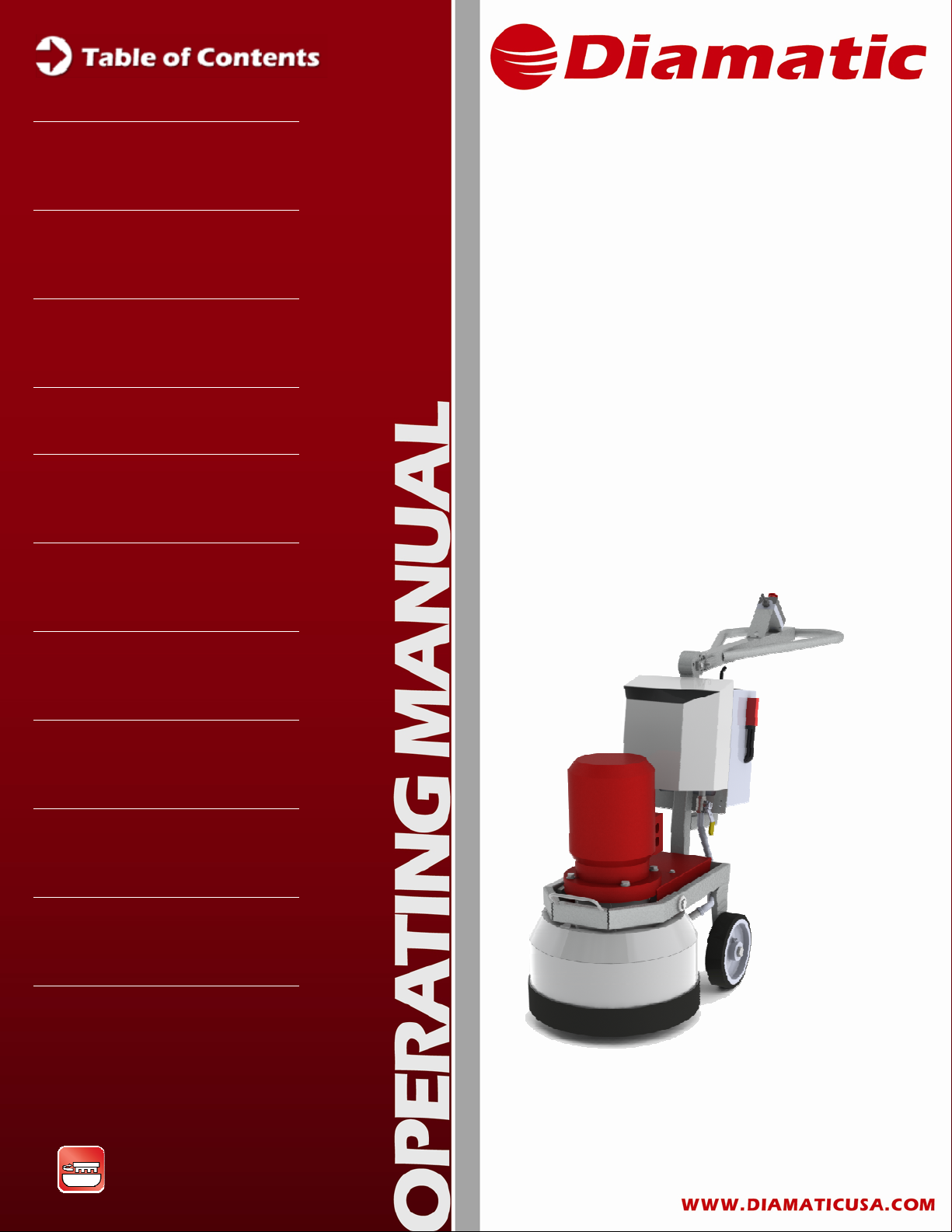
MODEL BMG-780 GRINDER
OPERATING MANUAL
SECTION 2 SAFETY INSTRUCTIONS
Technical Data 1
JANUARY 2008
Safety Instructions 2
General 3
Transport 4
Initial Operation 5
Operation 6
MODEL
BMG-535
Planetary Grinder
Maintenance 7
Electrical Systems 8
Fault Diagnosis 9
Spare Parts 10
Grinding & Polishing
Grinding & Polishing
1
Page 2

SECTION 1 TECHNICAL DATA
CONTENTS – SECTION 1
1.1 Rating
1.2 Unit specifications
1.3 Operative range and correct usage
1.4 Stand-by power supply
1.5 Machine type designation
MODEL BMG-535 GRINDER
OPERATING MANUAL
APRIL 2009
Grinding & Polishing
1
Page 3
SECTION 1 TECHNICAL DATA
1.1 RATING
Unit / Designation: Grinding Machine
Machine Type: BMG-535
Manufacturer:
MODEL BMG-535 GRINDER
OPERATING MANUAL
APRIL 2009
US BV
13201 North Santa Fe Utrechthaven 12
Oklahoma City, OK 73114 3433 PN Nieuwegein
United States of America THE NETHERLANDS
Local: 405-478-3440 T +31(0)30 – 601 88 66
toll-free: 800-256-3440 F +31(0)30 – 601 83 33
1.2 UNIT SPECIFICATIONS
Technical Data:
Grinding Machine BMG-535
Power Consumption 7.5 kW
Connected loads 220V, Three phase, 25.2A
Connected loads 440V, Three phase, 14.4A
Dimensions:
BMG-535
Length 37.5 in / 950 mm
Width 23 in / 580 mm
Height 49.25 in / 1250 mm
Weight 617 lbs / 280 kg
Grinding & Polishing
2
Page 4
MODEL BMG-535 GRINDER
SECTION 1 TECHNICAL DATA
1.3 OPERATIVE RANGE AND CORRECT USAGE
The BMG-535 is exclusively designed to process horizontal
surfaces. The machine must not be used for other purposes. The
manufacturer will not be liable for damage resulting from
incorrect usage. In these cases, the user takes responsibility for
all risks.
1.4 STAND-BY SUPPLY (GENERATOR)
If the BMG-535 is to be operated using power from a generator,
the generator must be operated in accordance with the current
U. S. National Electric Code guidelines or European VDE
standards, as appropriate (this applies, but is not limited to, the
protective earth conductor in particular) in order to ensure that all
safety devices are functioning and to eliminate possible damage
to electrical components.
OPERATING MANUAL
APRIL 2009
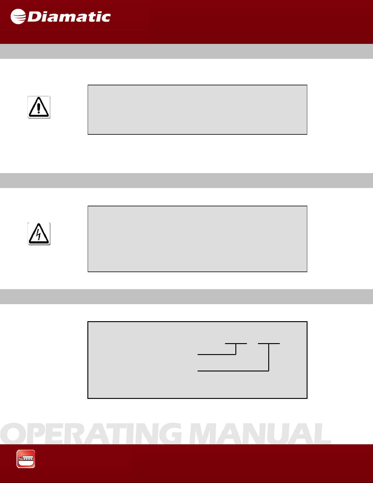
1.5 MACHINE TYPE DESIGNATION
BMG – 535
Product Type
Working width in mm
Grinding & Polishing
3
Page 5

SECTION 2 SAFETY INSTRUCTIONS
CONTENTS – SECTION 2
2.1 Warnings and symbols
2.2 Organizational measures
2.3 Personnel selection and qualification
2.4 Safety precautions applicable to some operating sequences
2.5 Special work within the scope of use of the equipment and maintenance
activities as well as repairs during operation
MODEL BMG-535 GRINDER
OPERATING MANUAL
APRIL 2009
2.6 Definition of the safety off position
2.7 General Safety Considerations
2.8 Electrical engineering regulations
Grinding & Polishing
4
Page 6
SECTION 2 SAFETY INSTRUCTIONS
2.1 WARNINGS AND SYMBOLS
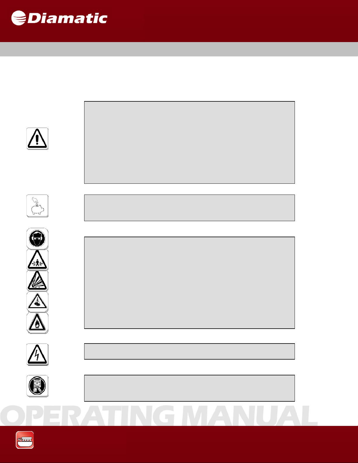
The following denominations and symbols are used in the Operating Instructions
to highlight areas of particular importance:
Symbol of operational safety.
In these Operating Instructions this symbol will be
shown next to all safety precautions that are to be
followed to maximize safety and equipment
performance. Follow these instructions and take
special care in these circumstances. In addition to
these instructions, the general safety precautions and
accident prevention guidelines are also to be followed.
MODEL BMG-535 GRINDER
OPERATING MANUAL
APRIL 2009
Particular details regarding the economical use of the
equipment.
Information, instructions and restrictions with regard to
possible risks to persons, property or equipment.
Warning of dangerous voltages.
Indicates protective devices in electrical appliances.
Grinding & Polishing
5
Page 7

SECTION 2 SAFETY INSTRUCTIONS
Indicates where consultation with the manufacturer is
required.
Instructions relating to periodic checks.
Reference to important instructions contained in the
Operating Instructions.
MODEL BMG-535 GRINDER
OPERATING MANUAL
APRIL 2009
2.2 ORGANIZATIONAL MEASURES
In addition to these Operating Instructions, general and legal regulations
regarding accident prevention and environmental protection must be complied
with per local regulations.
Such duties may, for example, relate to the handling of hazardous substances, or
the provision and wearing of personal protection equipment, as well as
compliance with traffic regulations.
The Operating Instructions must be supplemented by other instructions, including
the duty to supervise and report incidents relating to particular working practices,
for example work organization, work procedures and personnel safety.
Personnel entrusted with working with the machine must read and understand
the Operating Instructions before starting work, paying specific attention to the
Safety information. To read these instructions after work has commenced is too
late. This particularly applies to incidental activities such as setting up the
equipment, carrying out maintenance work or training staff to work with the
machine.
These Operating Instructions are to be kept with the machine, and
must be within reach at all times!
Grinding & Polishing
6
Page 8

SECTION 2 SAFETY INSTRUCTIONS
From time to time the working practices of the operators are to be checked by a
supervisor, especially regarding awareness of safety and hazards.
Operators must tie back long hair, and not wear loose clothing or jewelry
including rings. There is a risk of injury by items getting caught, or being drawn
into moving machinery.
:
Use personnel protection equipment if necessary or required by
local regulations! Take notice of all safety and hazard notices on
the machine!
All safety and hazard notices at or on the machine must be kept complete and
legible.
If safety-critical changes occur to the machine or its working method, the
machine must be shut down immediately. The cause of the fault must be
established and remedied.
Changes, additions or conversions to the machine must not be
made, without the manufacturer’s permission!
This applies in particular to the fitting and adjustment of safety devices.
Spare parts must comply with the technical requirements specified by the
manufacturer. This is always guaranteed if original spare parts are used.
Intervals for recurring checks and inspections specified in these Operating
Instructions must be complied with.
To perform maintenance work correctly, it is imperative to be equipped with the
proper tools for the task.
The location and the operation of fire extinguishers must be made known on
each work site.
Take note of the facilities for reporting and fighting fires.
MODEL BMG-535 GRINDER
OPERATING MANUAL
APRIL 2009
Grinding & Polishing
7
Page 9

MODEL BMG-535 GRINDER
OPERATING MANUAL
SECTION 2 SAFETY INSTRUCTIONS
2.3 PERSONNEL SELECTION AND QUALIFICATION
Fundamental duties:
Work on the machine may only be undertaken by trained personnel.
Only trained personnel may be employed. Note the statutory minimum age.
Clearly specify the responsibilities of personnel for operation, setting up,
servicing and maintenance work.
Make sure that only authorized personnel operate or work on the machine.
Define responsibilities of the machine operator, with regard to traffic safety
regulations, and inform him not to take instructions from third parties who may
not be complying with the local safety requirements.
Personnel, who are being trained to operate equipment, may only use the
machine under constant supervision of an experienced person.
.
Work on electrical equipment may only be performed by a skilled
electrician or by trained persons under the supervision of a skilled
electrician, as well as in accordance with the local electrical
engineering regulations.
APRIL 2009
2.4 SAFETY PRECAUTIONS APPLICABLE TO SOME
OPERATING SEQUENCES
Do not allow any method of working that impairs safety.
Recognized official procedures have to be used to ensure the machine is
operated in the safest and best conditions.
Grinding & Polishing
Only operate the machine when all safety devices, and related
safety equipment, are present and operational!
8
Page 10
SECTION 2 SAFETY INSTRUCTIONS
Check the machine visually for any damage and defects at least once a day.
In the event of operational malfunctions the machine must be shut down
immediately and secured.
Secure the work area around the machine in public areas
providing a safety distance of at least 6.5 feet (2 meters) from the
machine.
Faults must be immediately remedied.
Carry out the switch on, and switch off, operations in accordance with the
operations manual.
Before turning on the machine verify that no one can be endangered when the
machine starts up.
Do not turn off the dust collector while the machine is running.
All persons in the proximity of the machine must wear ear
protectors and safety shoes. In addition, the machine operator
must wear close fitting protective clothing.
Use only extension cables, used for extending the main cable, that
are sized and marked in accordance with the overall power
consumption of the machine and valid U. S. National Electric Code
guidelines or European VDE standards, as appropriate.
MODEL BMG-535 GRINDER
OPERATING MANUAL
APRIL 2009
Grinding & Polishing
9
Page 11

MODEL BMG-535 GRINDER
OPERATING MANUAL
SECTION 2 SAFETY INSTRUCTIONS
APRIL 2009
2.5 SPECIAL WORK WITHIN THE SCOPE OF USE OF THE
EQUIPMENT AND MAINTENANCE ACTIVITIES AS WELL
AS REPAIRS DURING OPERATION
Mechanical servicing work:
Put the machine in the Safety off position as described in Section 2.6 before
carrying out any service work on the machine.
Follow any special safety instructions in sections on servicing the machine. See
Section 7.
Service and maintenance intervals specified in these Operating Instructions, as
well as information on the replacement of parts must be undertaken and/or
complied with.
These activities may only be undertaken by qualified personnel.
The operator must be given information about maintenance and work procedures
before starting the cleaning process. This includes, but is not limited to the
following:
• Procedures that are related to normal operation
• Methods of tools adjustment on the machine, and its safety devices,
• All “ON and OFF” functions that have to be carried out according to the
operation manual
• Methods for maintenance and repair.
If the equipment is switched off in order to carry out maintenance, repair, or
adjustment, it must be secured against unintended restart.
Switch OFF and disconnect the machine from the power supply.
See Section 2.6 Safety off position for specific details.
Always dispose of the contents of the dust bin or of a connected dust collector
before loading the machine onto a vehicle.
Grinding & Polishing
10
Page 12

SECTION 2 SAFETY INSTRUCTIONS
Observe the local waste disposal regulations; in uncertain situations ask the next
higher authority.
Do not use any aggressive cleaning materials.
Only use lint-free cleaning cloths.
Always verify that any bolted connections that were loosened during service and
maintenance work are properly secure and tight.
If safety devices need to be removed or dismantled during service and repair,
these safety devices must be reinstalled, and inspected immediately after
completion of the servicing and repair work.
Make sure that process materials and replaced parts are disposed of safely and
in an environmentally friendly manner.
Make sure that electrical components used for replacement purposes comply
with the original parts and are correctly adjusted if necessary.
Work on electrical equipment may only be performed by a skilled
electrician or by trained persons under the supervision of a skilled
electrician, as well as in accordance with the local electrical
engineering regulations.
MODEL BMG-535 GRINDER
OPERATING MANUAL
APRIL 2009
2.6 DEFINITION OF THE SAFETY OFF POSITION
Definition
Putting the equipment in the Safety off position involves:
Grinding & Polishing
: The machine is in a safe condition where it cannot be a hazard.
• Switching off the machine.
• Switching off the dust collector (if being used).
• Waiting for all drives to stop.
• Disconnecting all power from the power source.
• Securing against unintended restart.
11
Page 13

SECTION 2 SAFETY INSTRUCTIONS
2.7 GENERAL SAFETY CONSIDERATIONS
MODEL BMG-535 GRINDER
OPERATING MANUAL
APRIL 2009
Any machine, if it is not used according to regulations, may be
hazardous during operation, set-up and servicing. The machine
owner is responsible for compliance with the safety regulations
during operation and maintenance, and for the use of safety
devices supplied with the machine, as well as the provision of
appropriate additional safety devices!
2.8 ELECTRICAL ENGINEERING REGULATIONS
Work on electrical equipment may only be performed by a skilled
electrician or by trained persons under the supervision of a skilled
electrician, as well as in accordance with the local electrical
engineering regulations.
Use only extension cables, used for extending the main cable, that
are sized and marked in accordance with the overall power
consumption of the machine and the U. S. National Electric Code
guidelines or European VDE standards, as appropriate.
The electrical components of the equipment must be inspected regularly. Defects
such as loose connections or scorched cables must be replaced immediately.
Call a skilled electrician or our Customer Service.
A second person must be in attendance while the electrician is working on the
equipment.
The work area must be secured against any third party entering the work area,
by means of a red and white safety chain and a danger sign. Use only tools that
are insulated against electricity.
Only start work after you are familiar with the electrical engineering regulations
that apply to the local area.
Only use multi-meters that comply with the regulations when troubleshooting.
From time to time check multi-meters to ensure that they are operating correctly.
Grinding & Polishing
12
Page 14

SECTION 3 GENERAL
CONTENTS – SECTION 3
3.1 Range of application
3.2 Scope of supply
3.3 Description of the machine
3.4 Operating elements
3.5 Electric components
3.6 Upper part
MODEL BMG-535 GRINDER
OPERATING MANUAL
APRIL 2009
3.7 Lower part
3.8 Tensioner upper belt
3.9 Tensioner lower belt
3.10 Pulley
3.11 Center pulley
3.12 Contra pulley
3.13 Driving pulley
3.14 Diamond tool holder
3.15 Diamond Tooling
3.16 Care and maintenance
Grinding & Polishing
13
Page 15

SECTION 3 GENERAL
3.1 RANGE OF APPLICATION
Typical ranges of applications for the BMG-535 are for example:
• To remove undulated concrete surfaces
• To prepare the surface for coatings
• To polish the surface
• To remove coating defects
• To remove glue residue
MODEL BMG-535 GRINDER
OPERATING MANUAL
APRIL 2009
3.2 SCOPE OF SUPPLY
Scope of supply of the machine:
• Grinding machine (BMG-535)
• Dust hose (Optional)
• Operating manual (1x)
Grinding & Polishing
14
Page 16
SECTION 3 GENERAL
3.3 DESCRIPTION OF THE MACHINE
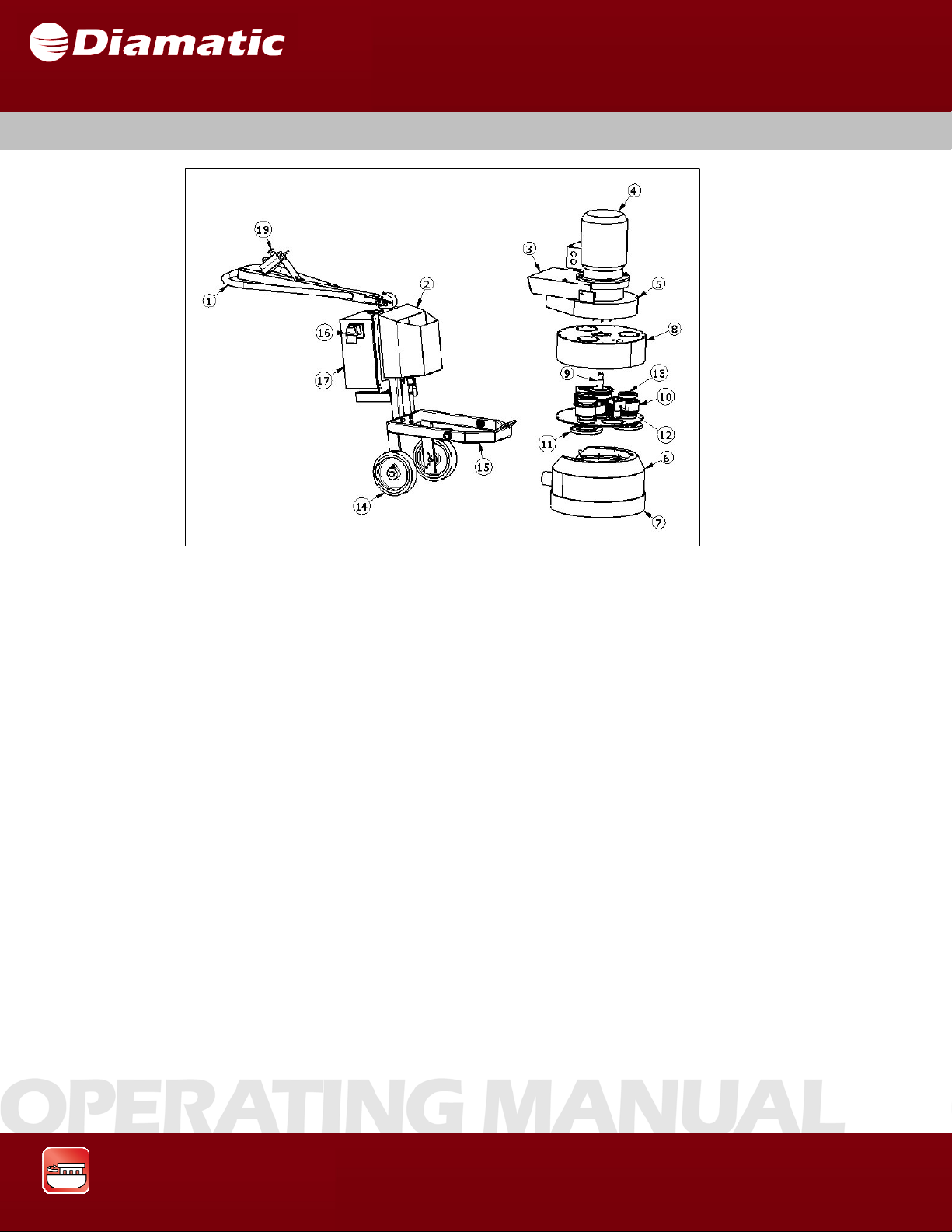
1 Steering Handle 8 Lower Housing 15 Lower Frame
2 Water Tank 9 Center Pulley 16 Electrical Plug
3 Cover, Upper Part 10 Lower Belt 17 Control Panel
4 Motor 11 Diamond Tool Holders 18 Safety Switch
5 Motor Mount Plate 12 Lower Belt Tensioner
6 Cover Housing 13 Pulley
7 Dust Control Seal 14 Wheel
The BMG-535 has a working width of 535 mm and gives excellent performance
due to its economic efficiency and easy handling.
The machine is capable of leveling uneven and undulating floors.
This process is suitable for an optimization of surfaces prior to blast
cleaning.
Alternately, the machine can be used to smooth floor surfaces as preparation for
coatings to be applied.
Depending on the application the diamond disc holder can be fitted with several
different types of diamond-grinding discs.
Fig. 3.1
MODEL BMG-535 GRINDER
OPERATING MANUAL
19
Pushbutton
APRIL 2009
Grinding & Polishing
15
Page 17
SECTION 3 GENERAL
The individual tooling heads rotate at approximately 1250 revs/min. The Lower
Housing rotates at approximately 82 revs/min.
3.4 OPERATING ELEMENTS
MODEL BMG-535 GRINDER
OPERATING MANUAL
APRIL 2009
Fig. 3.2
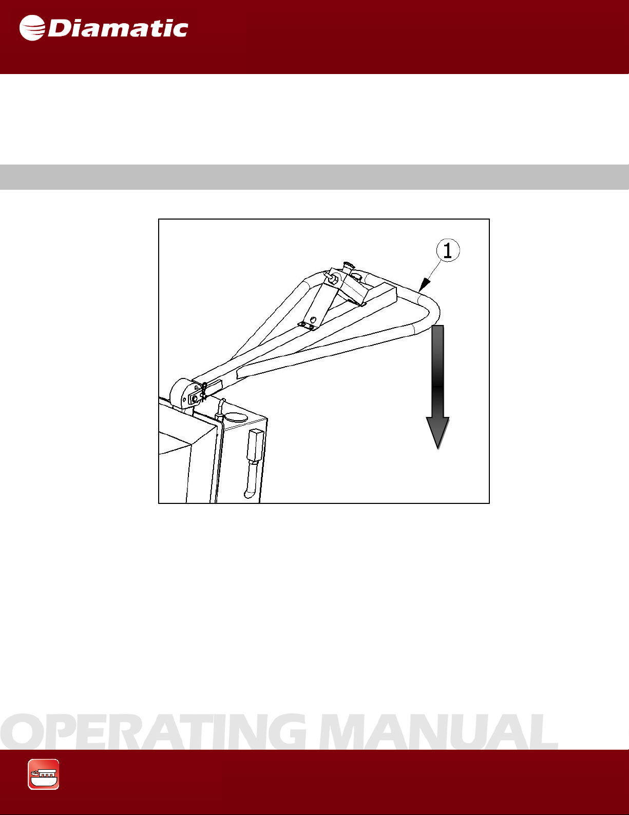
Before Switching on the BMG-535, the front part of the grinding machine
must be
lifted by pushing the handgrip (1) down toward floor level till the front of the
machine is approximately 4 inches (10 cm) from the ground.
Grinding & Polishing
16
Page 18
SECTION 3 GENERAL
h
3.5 ELECTRIC COMPONENTS
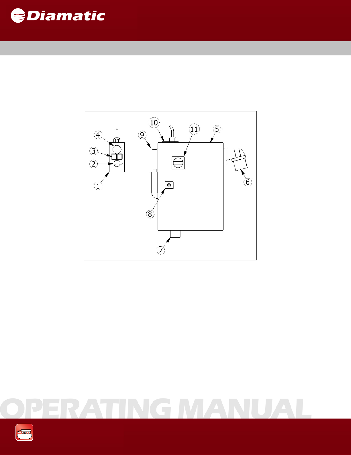
The Pushbutton mounted on the Steering Handle is used to control all elements
of the machine. The Control Panel contains the main disconnect, safety switch,
and hour meter.
MODEL BMG-535 GRINDER
OPERATING MANUAL
APRIL 2009
Fig. 3.3
1 Pushbutton Enclosure 5 Panel Enclosure 9 Safety Switch
2 FWD/REV Switch 6 Panel Plug 10 Hour Counter
3 Start/Stop Buttons 7 Motor Plug 11 Main Disconnect Switc
4 Emergency Stop 8 Panel Lock
Start/Stop Buttons
The green start button turns on the machine. The red stop button turns off the
machine.
Grinding & Polishing
17
Page 19

SECTION 3 GENERAL
Emergency Stop
This red mushroom-shaped switch when pressed will immediately cut off
the power supply to the panel and motor and bring the machine to rest. To
restart the machine the switch must be reset.
FWD/REV Switch
The FWD/REV switch changes the direction of rotation of the head of the
machine. This switch must be changed when the head is not rotating, if it
is changed during operation it could result in damage to the machine or to
the work surface.
Hour Counter
The hour counter simply monitors the number of hours the machine has been
in operation.
MODEL BMG-535 GRINDER
OPERATING MANUAL
APRIL 2009
Safety Switch
This switch is spring loaded; it will turn off the power supply if the operator
loses control of the machining while operating and must be worn at all times.
Main Disconnect Switch
This switch controls the flow of electricity from the power source to the panel
and all subsequent electrical components.
Grinding & Polishing
18
Page 20
SECTION 3 GENERAL
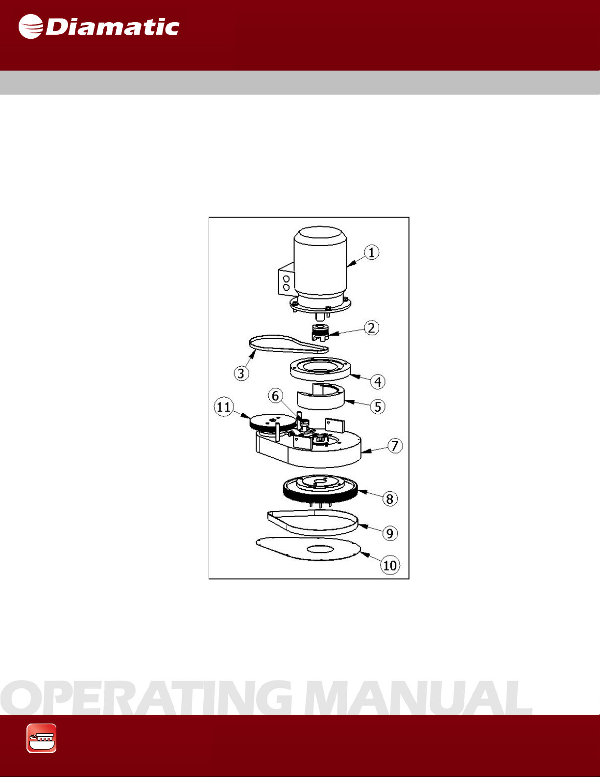
3.6 UPPER PART
The upper part of the BMG-535 is where the drive system for the machine is
located. The rotational drive is powered through a speed reduction drive belt and
pulley system, which also gives rotation to the grinder he ad and drive to the center
pulley. Upper Belt (item #3) in Figure 3.4 is set using an electronic belt tension
meter at the factory and set somewhere between 200-215 Hz. The Housing Drive
belt (item #9) is also set using an electronic belt tension meter at the factory and set
somewhere between 160-170 Hz.
MODEL BMG-535 GRINDER
OPERATING MANUAL
APRIL 2009
1 Motor 5 Spider bearing 9 Tensioner upper belt
2 Coupling 6 Motor housing 10 Contra pulley
3 Flange motor seat 7 Center pulley
4 Motor seat 8 Upper belt
Grinding & Polishing
Fig. 3.4
19
Page 21
SECTION 3 GENERAL
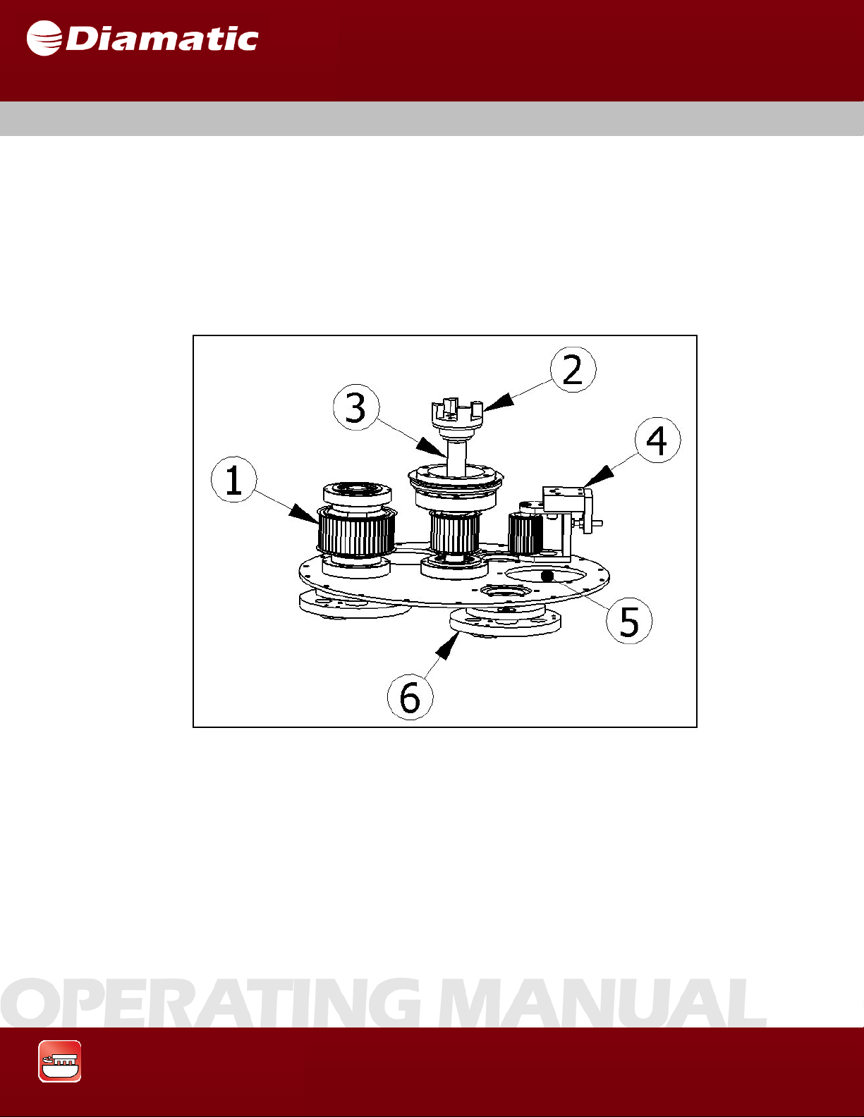
3.7 LOWER PART
The lower part of the BMG-535 is where the drive pulleys and the diamond tool
holders are fitted. On the driving pulley, there is a coupling which is driven by the
electric motor. Between the driving pulley and the driven pulley, there is the main
drive belt. This belt is tensioned at approximately 55-60 Hz with an electronic belt
tension meter. Under the pulleys there are the tool holders on which the diamond
discs can be fitted. The pulleys are covered by a protective housing which also
turns.
MODEL BMG-535 GRINDER
OPERATING MANUAL
APRIL 2009
Fig. 3.5
Grinding & Polishing
1 Tooling Pulley 4 Tensioner Lower Belt
2 Coupling 5 Inspection Hole
3 Driving Pulley 6 Diamond Tool Holder
20
Page 22
SECTION 3 GENERAL
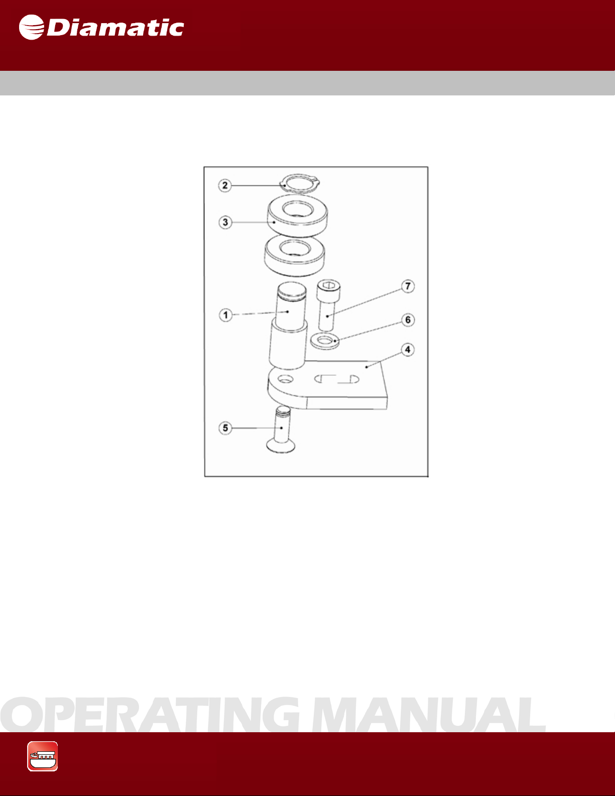
3.8 TENSIONER UPPER BELT
The upper belt tensioner keeps the upper belt tight. By taking off the cover of the
upper part, the tensioner can be accessed.
MODEL BMG-535 GRINDER
OPERATING MANUAL
APRIL 2009
1 Axle 5 Flat Head Socket Cap Screw
2
3 Bearing 7 Socket Head Cap Screw
4 Tensioner plate
Grinding & Polishing
Fig. 3.6
Retainingring
6 Flat Washer
21
Page 23
SECTION 3 GENERAL
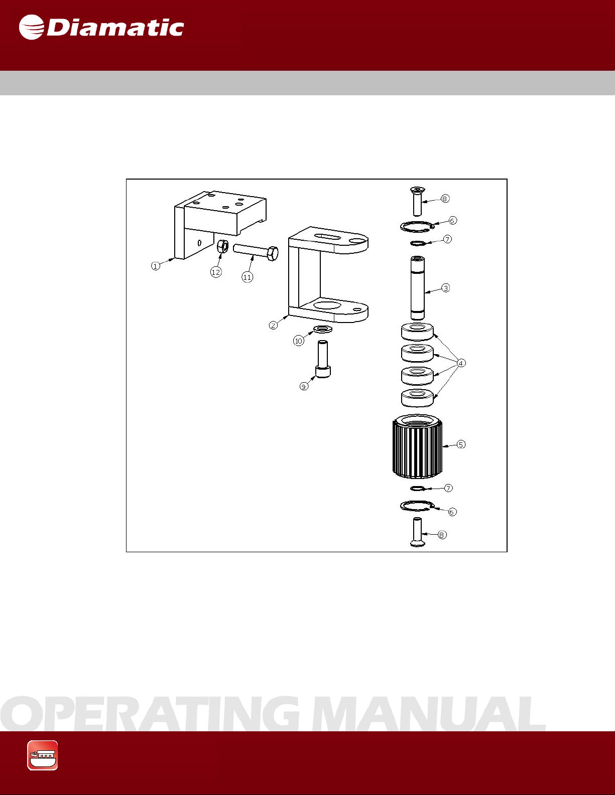
3.9 TENSIONER LOWER BELT
The lower belt tensioner keeps the lower belt tight. By taking off one of the two
inspection hole covers at the bottom of the lower plate the tensioner can be
accessed.
MODEL BMG-535 GRINDER
OPERATING MANUAL
APRIL 2009
Fig. 3.7
1 Holder 6 Retaining ring 11
2 Tensioner 7 Retaining ring 12
3 Axle 8 Flat Head Socket Cap Screw
4 Bearing 9 Socket Head Cap Screw
5 Pulley 10 Flat Washer
Grinding & Polishing
HexHeadCapScrew
HexNut
22
Page 24
SECTION 3 GENERAL
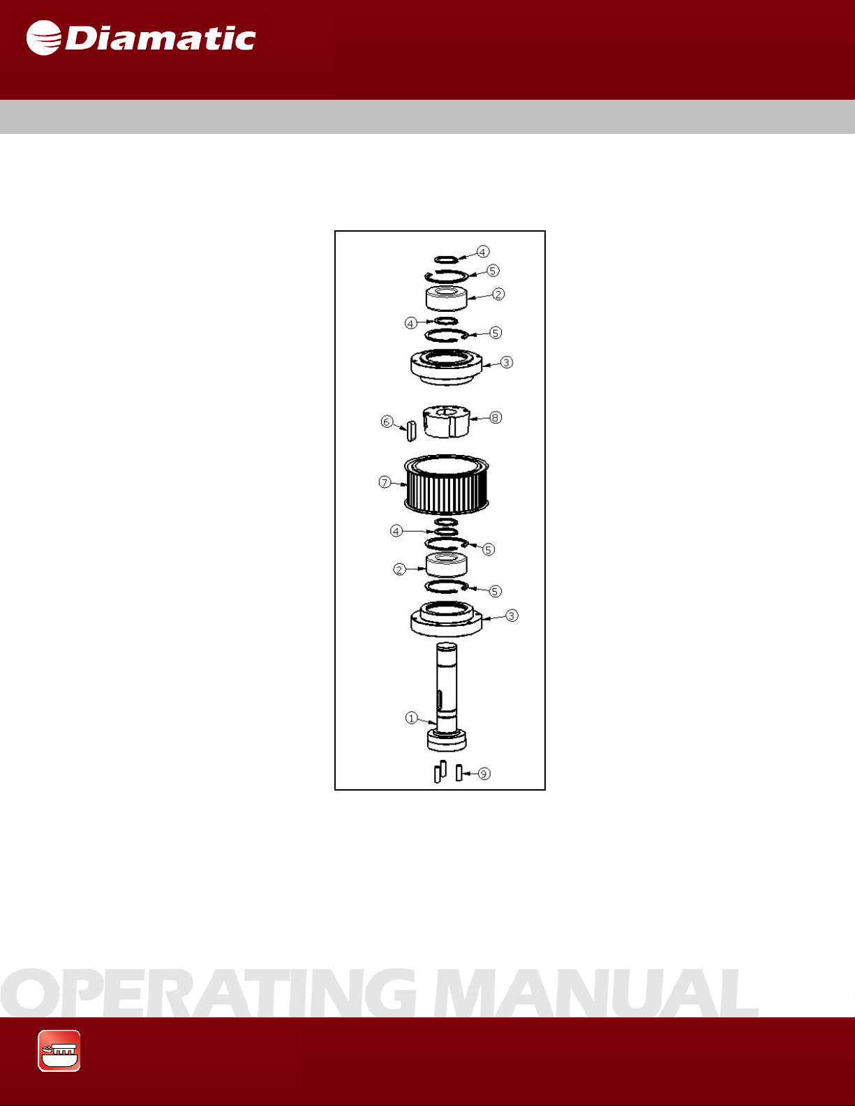
3.10 TOOLING DRIVE PULLEY
There are three pulleys in the machine. Under these pulleys the diamond discs are
fixed. The pulley is driven by the driving pulley through a belt. The pulley is fixed on
the lower housing with screws.
MODEL BMG-535 GRINDER
OPERATING MANUAL
APRIL 2009
Fig. 3.8
1 Axle 4 Retaining ring 7 Pulley
2 Bearin g 5 Retaini ng ring 8 Taper Lo ck Bushing
3 Bearing House 6 Key 9 Dowel Pin
Grinding & Polishing
23
Page 25
SECTION 3 GENERAL
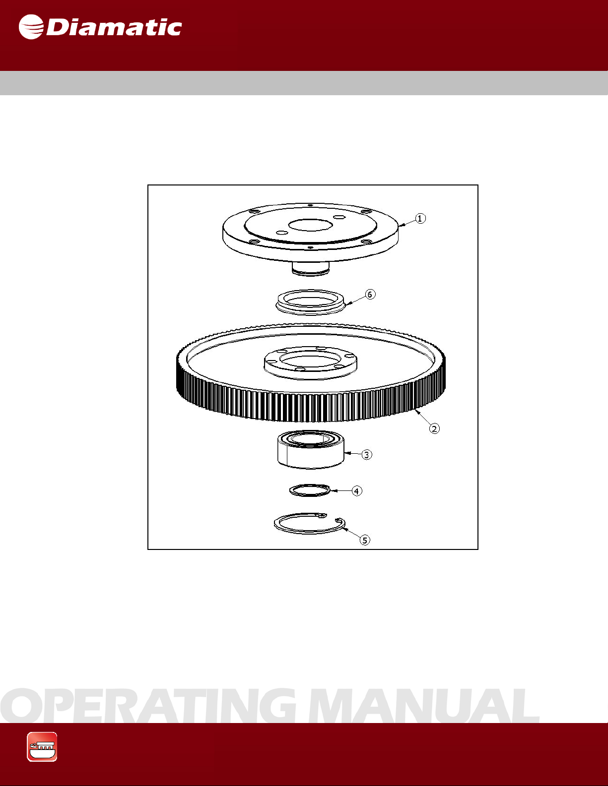
3.11 CENTER PULLEY
The center pulley will slow down the speed of the lower housing. The
six head cap screws connect the pulley with the lower housing.
MODEL BMG-535 GRINDER
OPERATING MANUAL
APRIL 2009
Fig. 3.9
Grinding & Polishing
1 Sprocket 4 Retaining ring
2 Pulley 5 Retaining ring
3 Bearing 6 V-Seal
24
Page 26
SECTION 3 GENERAL
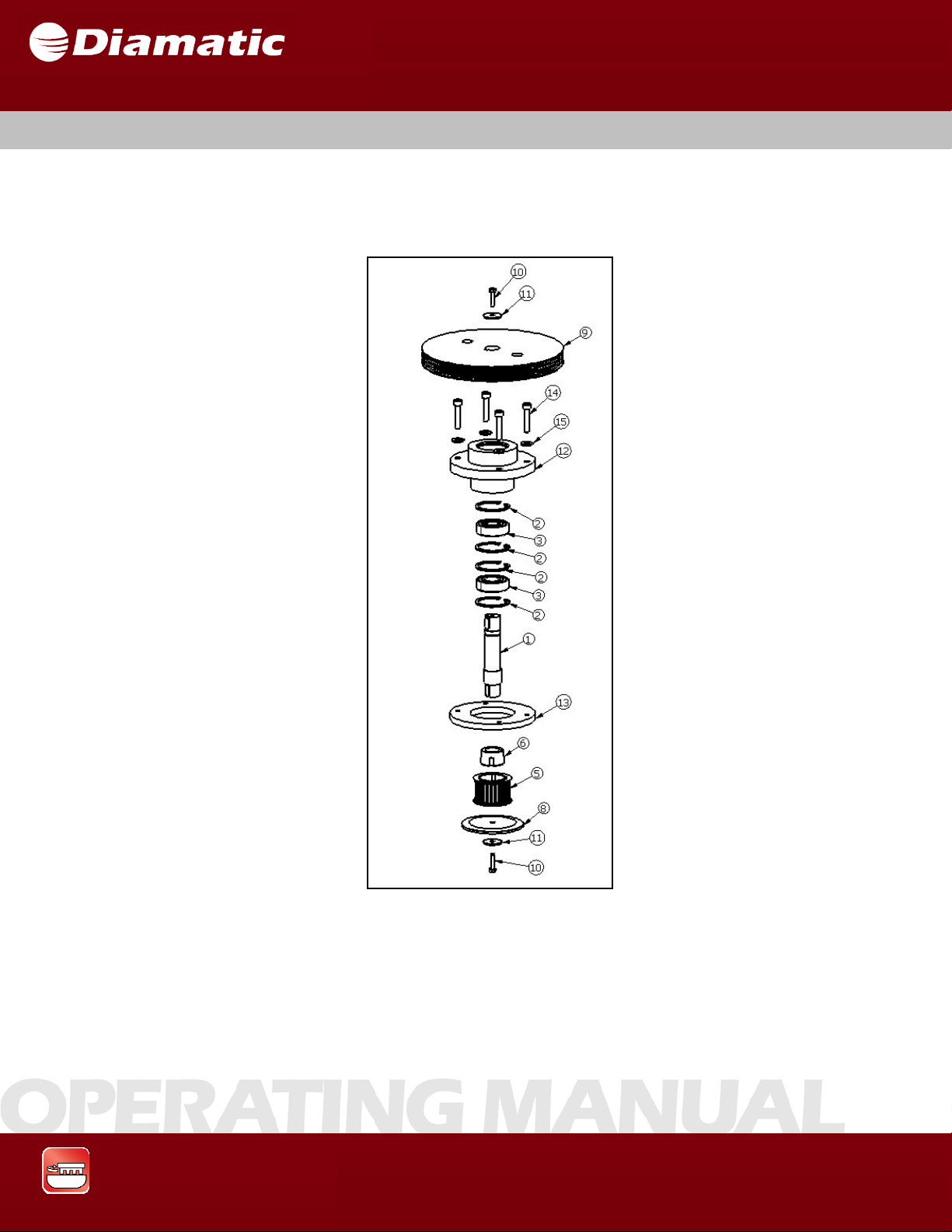
3.12 CONTRA PULLEY
The contra pulley gives a reduction of speed to the lower housing. The belt pulley is
driven by a belt from the motor pulley.
MODEL BMG-535 GRINDER
OPERATING MANUAL
APRIL 2009
Fig. 3.11
1 Axle 6 Tape r Lock Bushing 11 Flat Washer, Wide
2 Retaining Ring 7
3 Bearing 8 Flange 13 Ring
4 Retaining Ring 9 Belt Pulley 14 Socket Head Cap Screw
5 Pulley 10
Grinding & Polishing
Key
HexHeadCapScrew
12 Bearing House
15 Flat Washer, Narrow
25
Page 27
SECTION 3 GENERAL
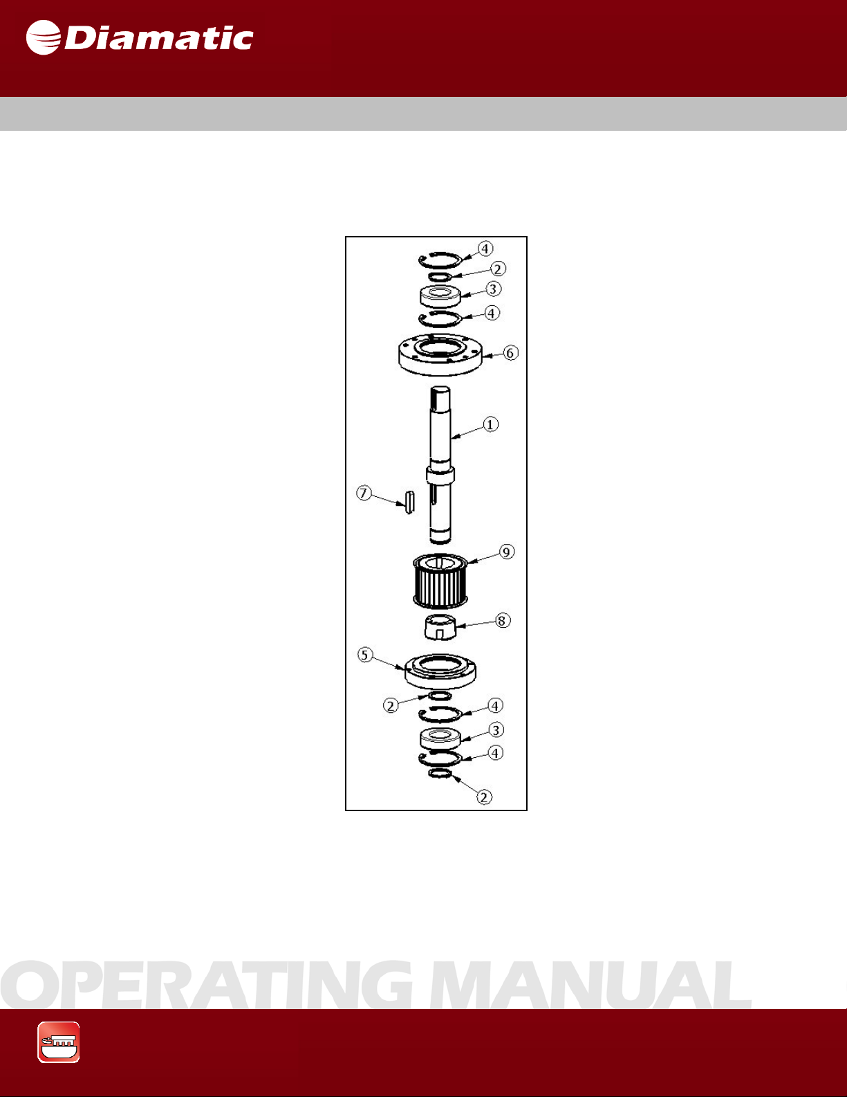
3.13 DRIVING PULLEY
On the driving pulley shaft, there is a coupling which is driven by the electric motor.
The driving pulley drives the three pulleys with a belt. The pulley is fixed on the
lower housing with screws.
MODEL BMG-535 GRINDER
OPERATING MANUAL
APRIL 2009
Fig. 3.11
1 Axle 5 Bearing House 9 Pulley
2 Retaining Ring 6 Bearing House
3 Bearing 7 Key
4 Retaining Ring 8 Taper Bushing
Grinding & Polishing
26
Page 28
MODEL BMG-535 GRINDER
SECTION 3 GENERAL
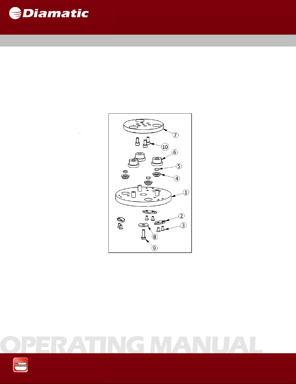
3.14 DIAMOND TIPPED CUTTING TOOL HOLDER
The diamond tool holder is connected under the pulley by three bolts.
There are 3 soft buffers so the energy from the diamond disc will be
softened. There are three magnets to attract any iron particles. The
centering stars are in place to ensure that the diamond disc cutting
tools will pass each other with working clearance. The cutting tools
must be locked with the three screws on each plate.
OPERATING MANUAL
APRIL 2009
Fig. 3.12
1 Holder for Tools 5 Magnet 9 Hex Head Bolt
2 Centering Star 6 Buffer Soft 10 Socket Head Cap Screw
3 Flat Head Socket Cap Screws 7 Buffer Plate
4 Magnet Holder 8 Flat Washer, Wide
Grinding & Polishing
27
Page 29

SECTION 3 GENERAL
3.15 DIAMOND TOOLING
There are three types of tooling that can be put under the diamond tooling.
The three types are: Diamond Segments
Polycrystalline (PCD) Diamond Segments
Polishing Resins
Diamond Segments
The diamond tools are designed for use on concrete floors.
These tools can be used to prepare a floor prior to coating or
as initial steps in a polishing process.
PCD Diamonds
MODEL BMG-535 GRINDER
OPERATING MANUAL
APRIL 2009
PCD’s can be used for removing epoxy, coating, and other floor
coatings.
Polishing Resins
Polishing resins are used in the final step of a polishing process.
For questions about the right set for the right floor treatment
use the tool scheme chart below or contact your distributor.
,
Grinding & Polishing
28
Page 30

SECTION 3 GENERAL
3.16 CARE AND MAINTENANCE
Special care and regular maintenance of the machine are imperative for proper
function and safety.
Pay attention to unusual noises or strong vibrations. Check for the cause of every
big change. Call a technician if you have doubts about the cause or when a
repair without a technician seems not possible without damages. Only use
genuine parts.
Generally the grinding machine BMG-535 requires very little special attention
regarding its maintenance.
Verify that any wastes or fiber residues do not remain in the area of the grinding
disc.
Depending upon the use of the machine the pulley should be checked about
every 200 hours.
Before using the machine you should always verify that all bolted connections
are secure and tight.
Use of non-original replacement components or wear parts may
void the machine warranty.
MODEL BMG-535 GRINDER
OPERATING MANUAL
APRIL 2009
Grinding & Polishing
29
Page 31

SECTION 3 GENERAL
________________________________________________________________
Notes
________________________________________________________________
MODEL BMG-535 GRINDER
OPERATING MANUAL
APRIL 2009
Grinding & Polishing
30
Page 32

Page 33

SECTION 4 TRANSPORT
CONTENTS – SECTION 4
4.1 Unit specifications
4.2 Manual mode of moving the machine
4.3 Transport with cranes or lifts
4.4 Transport of the machine with vehicle
4.5 Operation of the machine while grinding
MODEL BMG-535 GRINDER
OPERATING MANUAL
ARRIL 2009
4.1 UNIT SPECIFICATIONS
Model BMG -535
Dimension (inches) 37.5 x 23 x 49.5
Dimensions (mm) 950 x 580 x 1250
Weight 620 lbs / 280 kg
Grinding & Polishing
32
Page 34

MODEL BMG-535 GRINDER
SECTION 4 TRANSPORT
4.2 MANUAL MODE OF MOVING THE MACHINE
To move the machine, press down the handgrips of the machine (see fig.3.2) until
the front part rises off the ground and the machine is well balanced. It can now be
pushed around on its wheels.
The machine should only be moved around after attachments are disconnected,
such as:
• Generator, (i f being employed)
• Dust collection unit, (optional extra)
OPERATING MANUAL
ARRIL 2009
Grinding & Polishing
33
Page 35

MODEL BMG-535 GRINDER
OPERATING MANUAL
SECTION 4 TRANSPORT
4.3 TRANSPORT WITH CRANES OR LIFTS
If the machine is to be transported by a crane or a fork lift, verify that the lifting
strap(s) has sufficient capacity to support the weight of the machine. The gross
weight is shown in Section 4.1 Unit specifications and also on the serial number
plate on the machine.
Fasten any lifting slings to the lower machine frame. The lower frame is also a
suitable fixing point for fastenings or tie-downs to be used during transportation
of the machine on a vehicle.
4.4 TRANSPORT OF THE MACHINE WITH VEHICLE
When transporting the machine in a vehicle, always drive carefully and in a
manner to avoid the machine shifting. Secure the machine with a tightening load
strap over the lower frame. Use at least two load straps, and tighten down to the
body of the vehicle.
ARRIL 2009
4.5 OPERATION OF THE MACHINE WHILE GRINDING
The machine must always be operated in accordance with the instructions given
in Section 5.2 “Initial Operation”.
Grinding & Polishing
34
Page 36

SECTION 5 INITIAL OPERATION
CONTENTS – SECTION 5
5.1 Preparation for initial operation
5.2 Initial operation
MODEL BMG-535 GRINDER
OPERATING MANUAL
APRIL 2009
Grinding & Polishing
35
Page 37

MODEL BMG-535 GRINDER
SECTION 5 INITIAL OPERATION
5.1 PREPARATION FOR INITIAL OPERATION
Before start-up, all operating personnel must be familiar with the
safety regulations given in this manual.
• Put the grinding machine and the filter unit onto the surface to be treated.
• Attach the appropriate diamond tooling that is required for the particular
process. Please read Section 7 Maintenance of this manual.
• Using the correct cables, connect the machine and the dust collector to
the electricity supply point. These electric supply points should be
protected and equipped with an Fl-switch. In case of doubt, ask the local
safety officer.
• Check the extension cable for external damage.
OPERATING MANUAL
APRIL 2009
• Check the dust hose for damage.
• Connect the grinding machine and the dust collector unit with the flexible
dust hose. Use hose clamps at the connections.
• Make sure the dust bin of the dust collector unit is empty.
If problems with the BMG-535 arise during the assembly or startup, call a qualified person for help. Work on electrical equipment
may only be undertaken by qualified personnel.
Any machine, if it is not used according to the regulations, may
be hazardous to the operating, set-up and service personnel.
The equipment owner is responsible for compliance with the
safety regulations during operation and maintenance of safety
devices supplied with the machine as well as the provision of
appropriate additional safety devices.
Grinding & Polishing
36
Page 38
SECTION 5 INITIAL OPERATION
5.2 INITIAL OPERATION
MODEL BMG-535 GRINDER
OPERATING MANUAL
APRIL 2009
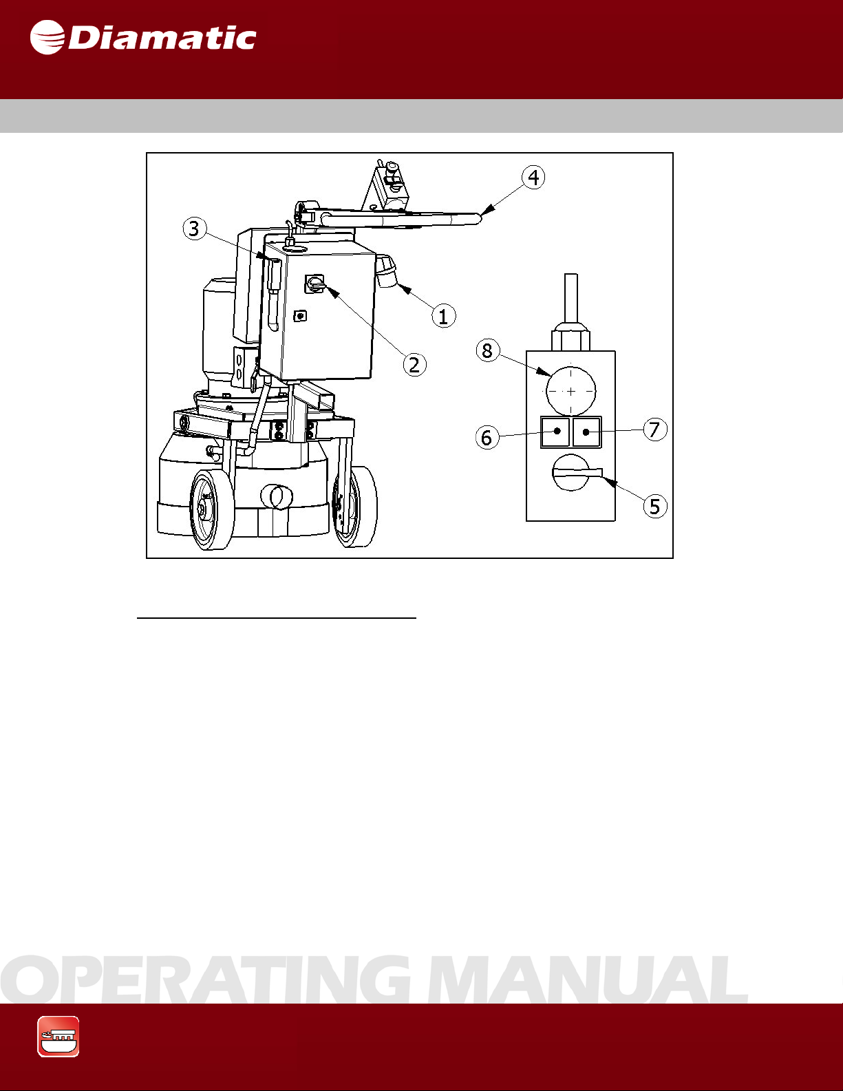
Fig. 5.1
Switching on the grinding machine:
• Make sure the motor is connected to the plug on the bottom of the panel
with the supplied cord.
• Make sure the electrical disconnect switch (2) on the outside of the panel
is turned to the off position.
• Connect the machine to the electrical outlet (1) with an extension cable
that complies with the appropriate European or U.S. NEC guideline, as
appropriate.
• Turn the electrical disconnect switch (2) on the outside of the panel to the
“ON” position.
• Put the safety cord on to your wrist and make sure the other end is insert ed
into the SAFETY SWITCH (3).
• Press down both handgrips (4) until the front part rises approximately 4
inches (10 cm) from the ground.
Grinding & Polishing
37
Page 39

SECTION 5 INITIAL OPERATION
• Using the “FWD/REV” selector switch (5) determine the head rotation direction.
• Press the green “START” button (6) to start the machine.
• Now let down the grinding disc on the surface gently and begin the grinding work. Move
the machine slowly forward or reverse to start grinding or polishing. (See chapter 6).
Switching off the grinding machine:
• Push down on the handgrips (4).
• Push the red “STOP” button (7) on the operator control panel.
• In case of emergency, push the red “EMERGENCY STOP” button (8).
MODEL BMG-535 GRINDER
OPERATING MANUAL
APRIL 2009
Grinding & Polishing
38
Page 40

SECTION 5 INITIAL OPERATION
________________________________________________________________
Notes
________________________________________________________________
MODEL BMG-535 GRINDER
OPERATING MANUAL
APRIL 2009
Grinding & Polishing
39
Page 41

SECTION 6 OPERATION
CONTENTS – SECTION 6
6.1 Operation
6.2 Switching-off the machine
6.3 Trouble shooting
6.4 Safety shutdown
6.5 Restarting after a fault
6.6 Proceedings- before and after a stationary period
MODEL BMG-535 GRINDER
OPERATING MANUAL
APRIL 2009
Grinding & Polishing
40
Page 42

SECTION 6 OPERATION
6.1 OPERATION
Pay attention to following aspects during operation of the BMG-535.
Before beginning the grinding work, verify that all bolted connections are properly
secured and tight.
Before switching the machine on, make sure that all protective housings are fitted
and the dust collector unit is correctly connected.
Handle all plugs, cables, hoses and operating elements carefully. Avoid contact
with live wires.
Before grinding, clean the surface to be treated with a broom. There should not
be any debris such as stones, cloths or standing liquid on the surface.
Any obstructions in the surface to be treated, like concrete reinforcing steel or
other objects, should be removed from the work surface to prevent damage to
the machine seals and diamond discs.
These Operating Instructions are to be kept with the machine
and must be within reach at all times.
Only trained personnel may be employed. Note the statutory
minimum age. Specify clearly the responsibilities of personnel for
operation, set up, service and maintenance work.
Make sure that only authorized personnel operate or work on the
machine.
Regular inspection is necessary to prevent unplanned down time
of your grinding machine. See Section 7 Maintenance.
While using the dust collector unit, observe any special workers’
protection rules, and local regulations regarding waste disposal.
MODEL BMG-535 GRINDER
OPERATING MANUAL
APRIL 2009
Grinding & Polishing
41
Page 43

SECTION 6 OPERATION
The process described in Section 5.2 “Initial Operation” shall be followed during
the normal start up of the BMG-535 for daily operation.
If there are any doubts as to how to start up the machine, read
Sections 5.1 and 5.2 of this operating manual.
Verify that the electric cable and dust hose are clear from vehicle traffic, such as
forklifts and other equipment.
6.2 SWITCHING OFF THE MACHINE
To switch off the machine, push the red “STOP” button on the operator control
panel (7). See Figure 5.1 in Section 5.2 for additional details.
MODEL BMG-535 GRINDER
OPERATING MANUAL
APRIL 2009
Grinding & Polishing
42
Page 44

SECTION 6 OPERATION
6.3 TROUBLE SHUTDOWN
In case of emergency or operating trouble, such as vibrations or
loud noises, switch the machine off immediately by pushing the
Emergency Stop (E-Stop) button on the operator control panel
(8)
.
6.4 SAFETY SHUTDOWN
The machine has to be in its Safety off position before starting repair work. See
Section 2.6.
The local safety regulations are valid in all cases regarding the operation of the
machine and will always supersede any instructions provided in this manual.
Before performing inspection or maintenance work make sure
that all moving machine parts are stopped. Observe the Safety
off position, Section 2.6.
MODEL BMG-535 GRINDER
OPERATING MANUAL
APRIL 2009
6.5 RESTARTING AFTER A FAULT
Grinding & Polishing
The results of all electrical repair work must be verified using the
appropriate measurement techniques per the regulations stated
in the European VBG4 and VDE 0701 standards or per the
applicable U.S. guidelines, as appropriate. See also Section 5.2
Initial operation.
43
Page 45

MODEL BMG-535 GRINDER
OPERATING MANUAL
SECTION 6 OPERATION
APRIL 2009
6.6 PROCEEDINGS – BEFORE AND AFTER STATIONARY
PERIOD
Before a long stationary period:
If the grinding machine will be out of action for a long period of time, protect the
machine during storage per the following:
• Clean the machine and cover it with a tarp.
• Protect the electric motors from moisture, heat, dust and impacts.
• Remove flexible couplings from machine to keep from warping which can
cause uneven grind.
After a long stationary period:
Follow the steps listed in Section 5.1 “Initial Operation” of this manual.
Grinding & Polishing
44
Page 46

SECTION 6 OPERATION
________________________________________________________________
Notes
________________________________________________________________
MODEL BMG-535 GRINDER
OPERATING MANUAL
APRIL 2009
Grinding & Polishing
45
Page 47

Page 48

SECTION 7 MAINTENANCE
7.1 Recommendations
7.2 Maintenance and inspection list
7.3 Repairing
7.4 Grinding tool replacement / assembly
7.5 Upper Part
7.6 Lower part
7.7 Pulley maintenance
7.8 Other maintenance
7.9 Recommended Spares for Stock
7.10 Influences on the Grinding Pattern
CONTENTS – SECTION 7
MODEL BMG-535 GRINDER
OPERATING MANUAL
APRIL 2009
Grinding & Polishing
47
Page 49

SECTION 7 MAINTENANCE
7.1 RECOMMENDATIONS
Failures due to inadequate or incorrect maintenance may generate very high
repair costs and potentially long periods of down time for the machine. Therefore,
regular maintenance is required.
Operational safety and service life of the machine depend, among other things,
on proper maintenance.
The table in section 7.2 shows recommended service intervals for normal use of
the machine.
The recommended time periods are based upon uninterrupted operation. When
the indicated number of working hours is not achieved during the corresponding
period, the period can be extended. However, a full overhaul must be carried out
at least once a year.
Due to different working conditions, inspection and maintenance intervals may
vary. Prepare a suitable inspection schedule considering known working
conditions and experience.
Our specialists will be happy to assist with more advice.
Prior to any repair work on the machine and its drives, secure
the machine against unintentional activation. Put the machine in
its safety off position. Section 2.6
Follow additional operating and maintenance procedures of
OEM parts, if included, during your service and maintenance
work.
Pay attention to special notice given in instructions for electricmotors.
MODEL BMG-535 GRINDER
OPERATING MANUAL
APRIL 2009
Grinding & Polishing
48
Page 50

MODEL BMG-535 GRINDER
Operating hours/time period
Inspection points, and
maintenance instructions
12 hours after repairing Check all accessible screw connections for
tightness.
SECTION 7 MAINTENANCE
7.2 MAINTENANCE AND INSPECTION LIST
Daily and prior to starting work
Quarterly Clean the machine with a damp cloth.
Annually Full overhaul and cleaning of the complete
Verify all safety devices are working
correctly.
Check the power supply cable for damage.
Check the dust collector hose for damage.
Check the optional water tank and system
for damage, if applicable.
Check grinding disk coupling and remove
any foreign material and debris.
Check the grinding disc and the coupling
for wear.
Check the countersunk head screw of the
grinding disc for tightness.
Check the tension of the V-belt, adjust as is
required.
Check the brush dust seal.
machine.
Replacement of the pulley parts. (about
200 hours).
OPERATING MANUAL
APRIL 2009
Grinding & Polishing
49
Page 51

SECTION 7 MAINTENANCE
7.3 REPAIRING
As previously mentioned in Section 5.1 Initial operation, we recommend
conducting initial repair work on the machine with the support of personnel, by
taking this advice, maintenance personnel get the opportunity to be trained by an
expert on the machine.
Only repair work that could occur within the bounds of regular
of the machine, or work that is required to replace wear
described.
If parts or components are to be replaced, the following sequence(s) of
maintenance must be followed.
It is advisable to stock all spare or wear parts that cannot be obtained quickly. As
a rule, production standstill periods are more expensive than the cost for carrying
the corresponding spare part.
Screws that have been removed must be replaced with those of the same quality
(strength, material) and design.
Prior to any repair work on the machine and its drives, secure
the machine against unintentional activation. See Section 2.6.
Use of non-original replacement components or wear parts may
void the machine warranty.
MODEL BMG-535 GRINDER
OPERATING MANUAL
APRIL 2009
operation
parts, will be
Grinding & Polishing
50
Page 52
MODEL BMG-535 GRINDER
SECTION 7 MAINTENANCE
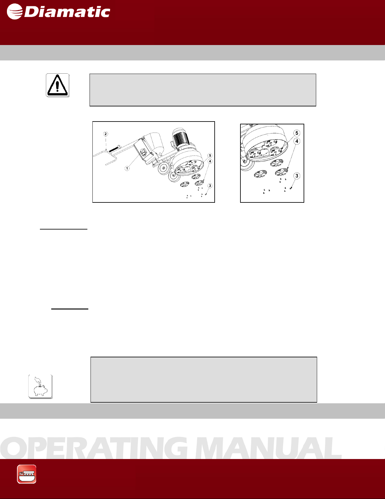
7.4 GRINDING DISC REPLACEMENT/ASSEMBLY
Prior to any repair work being carried out on the machine or its
drives, secure the machine against unintentional activation. See
Section 2.6.
OPERATING MANUAL
APRIL 2009
Disassembly:
1. Make sure that the power supply is disconnect from the electrical inlet (1).
2. Tilt the machine to the back with the help of the handgrips (2) and lay it down on the chassis.
You MUST add weight on the handle or otherwise secure the handle to the ground in order to
prevent the machine from tipping forward during change over.
3. Unscrew the three countersunk head screws (3).
4. Remove the grinding disc downwards (4).
Assembly:
5. Clean the diamond holder thorough (5).
6. Adjust the grinding disc in the centering (4).
7. Set in and tighten the countersunk head screw (3).
8. Tilt the machine forwards.
Fig. 7.1
When replacing the grinding disc, also check the condition of the
drive pulley and the diamond tool holders.
Always replace any worn fasteners.
7.5 UPPER PART
Grinding & Polishing
51
Page 53
SECTION 7 MAINTENANCE
MODEL BMG-535 GRINDER
OPERATING MANUAL
APRIL 2009
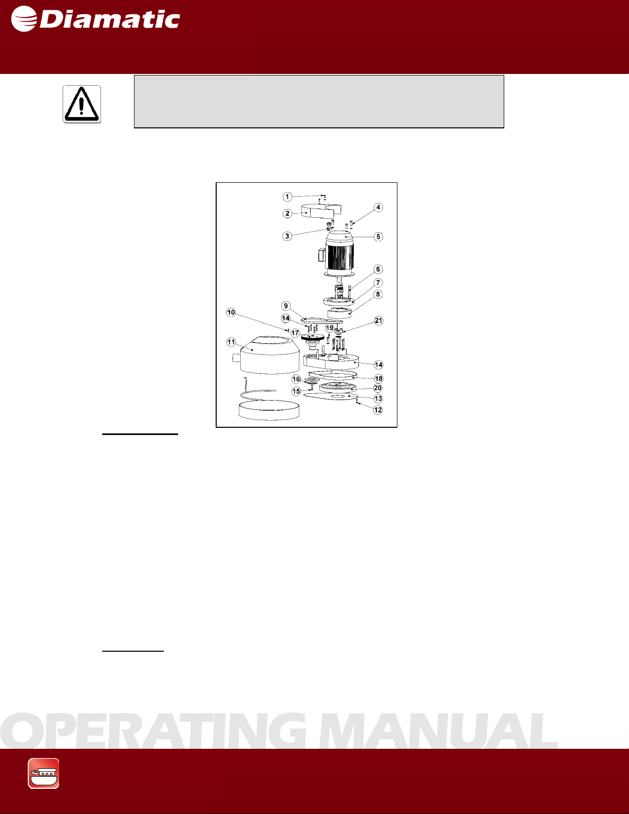
Fig. 7.2
Prior to any repair work being carried out on the machine or its
drives, secure the machine against unintentional activation. See
Section 2.6.
Disassembly:
1. Unscrew the bolts (1) on the topside, to enable the protection cover (2) to be
removed.
2. Disassemble the upper tensioner (3) and the bolts (4) to enable the motor (5) to be
removed.
3. Unscrew the long bolts (6) so the motor adapter flange (7) and the motor
mount (8) can be removed.
4. Now the belt (9) can be removed.
5.
The protection cover (11) can be removed by taking out the
bolts (10)
6. Unscrew the bolt (12) this will allow the under plate (13) to be removed.
7. Unscrew the bolts (14) and the bolt (15) to enable the rings (16) and the contra pulley
(17) to be taken out of the upper
drive.
8. Remove the belt (18).
9.
The center pulley (20) can be removed by unscrewing bolt
The coupling (21) must be taken off before you can disassembled the lower part.
10.
Assembly:
(19).
Assemble the parts in the reverse order that they have been disassembled.
Grinding & Polishing
52
Page 54
SECTION 7 MAINTENANCE
7.6 LOWER PART
MODEL BMG-535 GRINDER
OPERATING MANUAL
APRIL 2009
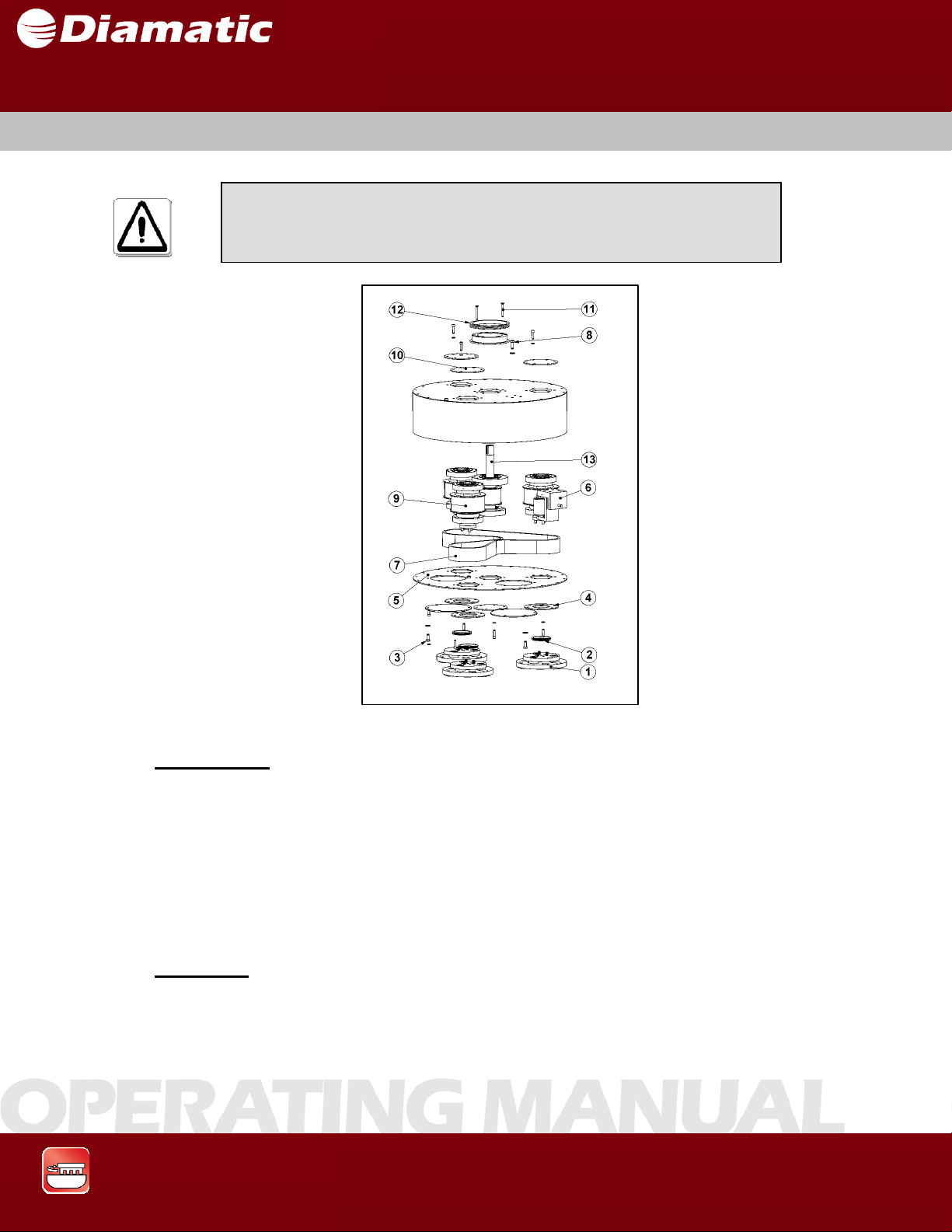
Prior to any repair work being carried out on the machine or its
drives, secure the machine against unintentional activation. See
Section 2.6.
Fig. 7.3
Disassembly:
1. Disassemble the diamond tool holders (1) and take off the v-seal (2).
2. Unscrew the bolts (3) from the underside, remove the rings (4), and the lower
plate (5).
3. Release the force on the lower tensioner (6), to enable the belt (7) t o b e
removed.
4. Unscrew the bolts (8) on the upper side to enable the pulleys (9), the
tensioner (6), the v-seal (12) and the rings (10) to be removed.
5. Unscrew the bolts (11) to enable the driving pulley (13) to be removed.
Assembly:
Assemble the parts in the reverse order that they have been
disassembled.
Grinding & Polishing
53
Page 55
7.7 TOOLING DRIVE PULLEY
SECTION 7 MAINTENANCE
Prior to any repair work being carried out on the machine or its
drives, secure the machine against unintentional activation. See
Section 2.6.
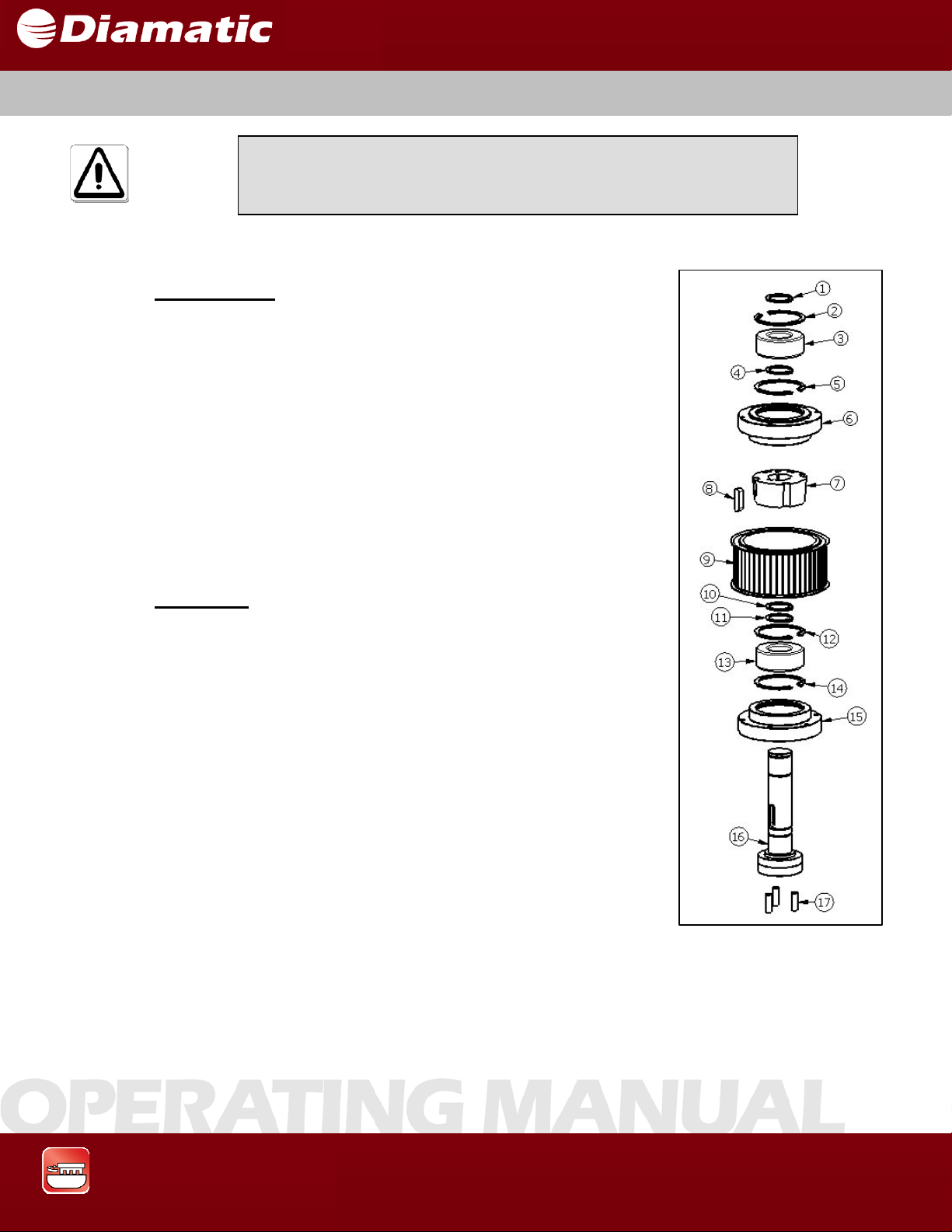
Disassembly:
1. Take off the retaining ring (1).
2. Remove the assembly of the retaining ring (2), bearing
(3), retaining ring (5), & bearing house (6) as one piece.
3. Take off the retaining ring (4) .
4. Unscrew the screws of the taper bush (7).
5. Remove the taper bush (7), the key (8) and the pulley (9).
6. Take off the retaining rings (10) & (11).
7. Remove the bearing housing assembly similar to step 2
but instead removing items (12), (13), (14), & (15).
8. It will be necessary to remove retaining rings (2), (5),
(12), & (14) to remove bearings (3) and (13) from
bearing house (6) and (15)
Assembly:
MODEL BMG-535 GRINDER
OPERATING MANUAL
APRIL 2009
• Make sure that bearing (3,13) and bearing housing (6,
15) are clean and rub the bearings with a few drops of
Loctite 609 on the inner diameter and outer diameter.
When installing new dowel pins (17) be sure to apply
Loctite 609 to them before pressing them into the
holes in the end of the shaft to hold them in place.
• Assemble the parts in the reverse order that they have
been disassembled.
F
i
g
.
7.4
Grinding & Polishing
54
Page 56

SECTION 7 MAINTENANCE
7.8 OTHER MAINTENANCE
Check the dust seals for wear and replace them at the time when
they no longer provide a good seal against dust emissions from the
machine. This will ensure that there is no damage caused to the surrounding
workspace and consequently saves additional cleanup charges from the job
client.
Clean the machine with a damp cloth.
Do not use high pressure water or compressed air for cleaning
the machine!
Apply Oil to the adjusting pin of the operating lever, and other moving parts with
clean oil can at regular intervals
MODEL BMG-535 GRINDER
OPERATING MANUAL
APRIL 2009
Grinding & Polishing
55
Page 57

MODEL BMG-535 GRINDER
It is highly recommended, that having the following spare parts on stock
will
avoid unplanned downtime and/or long equipment downtime that may result
from waiting for spare parts to ship.
Part No. Description Qty.
BG11924 Driving belt upper 1
BG11904 Driving belt middl e 1
BG11928 Driving belt lower 1
See chapte r 1 0 Diamond disc >1
The grinding pattern depends upon the surface being treated.
Depending on the required surface finish specified, the tools
(Diamond Wings),
will have to be changed in order to produce the best result. This may be done by
simply comparing the individual results of the tools.
For grinding applications, use the left-right switch of the machine every 330 sq.
ft. (100m2 ) to change the
rotation of the grinding head). This will also provide a
longer
life of the diamond tools, since they will wear down more equally.
Please note that this is NOT recommended for polishing applications.
Changing the rotation of the heads will result in large scratches that are difficult
to remove.
In the last 2mm of the diamond tools there is a loose buffer
material (no
diamond inside), changing the rotation helps ensure that the diamond tools do
not wear in such a way that diamonds are left on one side of the grinding disc
and the other side the diamonds are completely gone.
SECTION 7 MAINTENANCE
7.9 RECOMMENDED SPARES FOR STOCK
7.10 INFLUENCES ON THE GRINDING PATTERN
OPERATING MANUAL
APRIL 2009
Check the grinding pattern after new or other types of diamond
tools have been fitted.
By doing this, the operator can best produce efficient work, as
well as save
Grinding & Polishing
unnecessary wear and repair costs.
56
Page 58

SECTION 8 MAINTENANCE
CONTENTS – SECTION 8
8.1 Directions for electrical engineering
8.2 Electrical Schematic - 230V / 50 and 60 HZ
8.3 Control Panel Layout and Device Settings - 230V / 50 and 60 HZ
MODEL BMG-535 GRINDER
OPERATING MANUAL
APRIL 2009
Grinding & Polishing
57
Page 59

MODEL BMG-535 GRINDER
g
OPERATING MANUAL
SECTION 8 MAINTENANCE
8.1 DIRECTIONS FOR ELECTRICAL ENGINEERING
APRIL 2009
Work on electrical equipment or operating materials may only be
performed by a skilled electrician or by trained persons under the
guidance and supervision of a skilled electrician as well as in
accordance with the electrical en
ineering regulations.
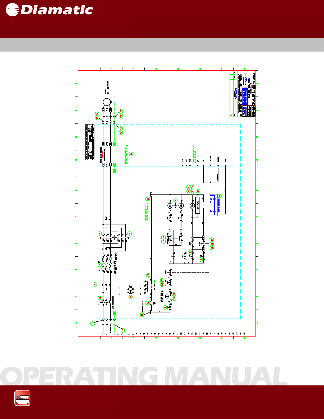
To identify electrical components, refer to the electrical schematics in
Section 8.2 or call a service center.
The results of all electrical repair work must be verified using the
appropriate measurement techniques per the regulations stated
in the European VBG4 and VDE 0701 standards or per the
applicable U.S. guidelines, as appropriate. See also Section 5.2
Initial operation.
Grinding & Polishing
58
Page 60
MODEL BMG-535 GRINDER
OPERATING MANUAL
SECTION 8 MAINTENANCE
8.2 ELECTRICAL SCHEMATICS - 23OV / 50 AND 60 HZ
APRIL 2009
Grinding & Polishing
59
Page 61
MODEL BMG-535 GRINDER
OPERATING MANUAL
SECTION 8 MAINTENANCE
APRIL 2009
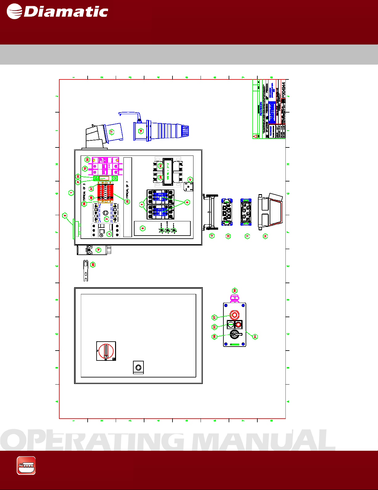
8.3 CONTROL PANEL LAYOUT FOR 23OV / 50 AND 60 HZ
Grinding & Polishing
60
Page 62

SECTION 8 MAINTENANCE
ITEM NUMBER QTY PN DESCRIPTION
1 1 P005037 ENCLOSURE W/ BACKPANEL
2 1 P004841 DISCONNECT, COMPLETE, BACK PANEL MOUNTED
3 1 P005033 MANUAL STARTER
4 2 P004828 CONTACTOR
5 1 P004781 MOTOR PROTECTOR, AUX CONTACT
6 2 P004822 CONTACTOR, AUX CONTACT, TOP MOUNT
7 1 P004893 CONTACTOR, MECHANICAL INTERLOCK
8 1 P004956 SOFT START
9 1 P004989 HOUR METER, W/ GASKET
10 1 P002024 CIRCUIT BREAKER
11 1 P004959 MALE INSERT
12 1 P004960 FEMALE INSERT
13 1 P003515 BULKHEAD MOUNTING
14 1 P004958 HOOD, SIDE ENTRY
15 2 P003081 CONNECTOR
16 3 P001041 CONDUIT FLEX
17 1 P000398 INLET PLUG, PANEL MOUNT
18 1 P000402 PLUG, CORD END, IEC, FEMALE
19 1 P004790 SAFETY SWITCH, DEADMAN WITH CORD GRIP P003095 INCLUDED
20 1 P004791 SAFETY SWITCH, DEADMAN, KEY W/ TETHER AND CLIP
21 1 P001044 CONNECTOR, 1/2" STRAIGHT
22 1 P002208 CONNECTOR, 1/2" 90 DEGREE, PMA
23 1 P004786 SWITCH, DOUBLE PUSHBUTTON
24 1 P005034 ENCLOSURE, POLYCARBONATE, 3 HOLE
25 3 P005035 SWITCH, CONTACT BLOCK, 1 NO, BASE MOUNTING
26 2 P005036 SWITCH, CONTACT BLOCK, 1 NC, BASE MOUNTING
27 1 P004922 SWITCH OPERATOR, E-STOP, TURN TO RELEASE
28 1 P004904 SWITCH, SELECTOR
29 1 P005014 TRANSFORMER CONTROL
30 1 P004876 CIRCUIT BREAKER
31 1 P004879 RELAY, INTERFACE, SPDT
32 1 P004880 RELAY, INTERFACE, SOCKET
33 1 P004881 RELAY, INTERFACE, HOLD DOWN CLIP
34 1 P004882 RELAY, INTERFACE PROTECTION MODULE RC CIRCUIT
35 7 717051 TERMINAL/ RK2.5-4/TERMINAL BLOCK, RED
36 1 717052 TERMINAL/ RK2.5-4/TERMINAL BLOCK, WHITE
37 1 717048 TERMINAL/ END BARRIER, KBL6-10 AND AP2.5-10 TERMINAL BLOCK
38 2 717045 TERMINAL/ ES35, TERMINAL END STOP
39 2 P003096 CORD GRIP 1/2" LARGE W/ LOCK NUT
40 1 P004576 XFMR TERMINAL COVER
41 1 P002050 RECTIFIER, FULL WAVE BRIDGE
MODEL BMG-535 GRINDER
OPERATING MANUAL
APRIL 2009
Grinding & Polishing
61
Page 63

Page 64

SECTION 9 FAULT DIAGNOSIS
CONTENTS – SECTION 9
9.1 Troubleshooting - grinding machine
9.2 Troubleshooting - electrical system
MODEL BMG-535 GRINDER
OPERATING MANUAL
APRIL 2009
Grinding & Polishing
63
Page 65

MODEL BMG-535 GRINDER
SECTION 9 FAULT DIAGNOSIS
9.1 TROUBLESHOOTING – GRINDING MACHINE
Fault Possible Cause Remedy
Excessive vibration Imbalance due to worn or
Unusual noises
Reduced or no
grinding
performance
Prior to any repair work on the machine or its drives, the
machine must be secured against unintentional activation. Put
the machine in its Safety off position. See section 2.6.
Replace all worn or
broken grinding tools.
PU-belt is too tight.
Screws worked loose on the
grinding disk(s)
Defective bearing.
Wrong tension of the belt.
Defective motor bearing.
Debris deposit on the
broken parts.
Release the tension of
the upper belt.
Tighten the counter-
sunk head screws on the
grinding disc.
Check the bearing on
the axle drive shaft and
replace if necessary.
Check the tension of the
belt, replace the belt if
necessary.
Change the motor.
Clean the coupling.
coupling.
Grinding tools have reached
the maximum permissible
wear.
Inappropriate grinding tool for
the application.
Too low tension of the belt.
Replace the worn parts.
Replace the grinding
tools with appropriate
grinding tools for the
surface to be treated.
Re-tension the belt.
OPERATING MANUAL
APRIL 2009
Grinding & Polishing
64
Page 66

MODEL BMG-535 GRINDER
g
SECTION 9 FAULT DIAGNOSIS
9.2 TROUBLESHOOTING – ELECTRICAL SYSTEM
Fault Possible Cause Remedy
Motor does not
switch on
Motor turns off
while running
Work on electrical equipment or operating materials may only be
performed by a skilled electrician or by trained persons under the
guidance and supervision of a skilled electrician as well as in
accordance with the electrical en
ineering regulations.
Prior to any repair work on the machine or its drives, the
machine must be secured against unintentional activation. Put
the machine in its Safety off position. See section 26.
Under voltage trip due to
power interruption
Defective Component
GFCI device
tripped
Check the main power
supply for proper voltage
and switch on again.
Troubleshoot and
replace defective
component.
Reset GFCI device and
retry. If device trips
again, determine cause
and replace.
Motor protection switch
triggered because of
overload.
Motor protector switch tripped
because of low or under
voltage condition.
Motor defective.
Reduce additional load
or increase extension
cord wire size.
Increase extension cord
wire size.
Have motor checked by
a trained professional to
confirm.
OPERATING MANUAL
APRIL 2009
Grinding & Polishing
65
Page 67

SECTION 9 FAULT DIAGNOSIS
________________________________________________________________
Notes
________________________________________________________________
MODEL BMG-535 GRINDER
OPERATING MANUAL
APRIL 2009
Grinding & Polishing
66
Page 68

SECTION 10 SPARE PARTS
CONTENTS – SECTION 10
10.1 Spares Parts - BMG-535
MODEL BMG-535 GRINDER
OPERATING MANUAL
APRIL 2009
Grinding & Polishing
67
Page 69
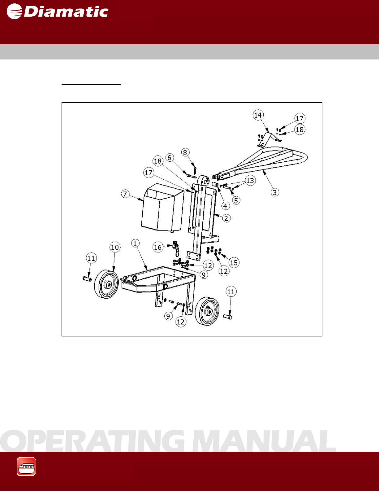
SECTION 10 SPARE PARTS
10.1 SPARE PARTS – BMG-535
Frame Assembly
MODEL BMG-535 GRINDER
OPERATING MANUAL
APRIL 2009
Grinding & Polishing
68
Page 70
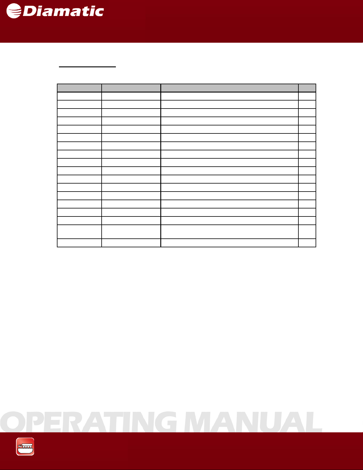
SECTION 10 SPARE PARTS
Frame Assembly
ITEM NO. PART NUMBER DESCRIPTION QTY.
1 PG-10306 MAIN FRAME ASSEMBLY 1
2 PG-10305 POWERBOX FRAME ASSEMBLY 1
3 BG005341 STEER 1
4 PA-10868 HANDLE BUSHING 1
5 BG11757 PIN 1
6 BG11750 PIN, K NURLED HA NDLE 1
7 PG-10334 WATE R TA NK , IMPERIAL 1
8 CP-10263 HAIRPIN COTTER PIN 1
9 800838 M12 X 1.75 X 40MM HEX HEAD CAP SCREW 6
10 4501710 WHEEL 2
11 PA-10876 WHEEL SUPPORT, MAIN FRAME 2
12 800798 WASHER, 1 2M M , NA RROW 10
13 CP-10036 15MM RETA INING RING, EXTERNAL 2
14 PA-10852 BRACKET / ST E ER 1
15 800842 M12 X 1.75 HEX NUT 4
16 BG11860 WATER TAP 1
MODEL BMG-535 GRINDER
OPERATING MANUAL
APRIL 2009
17 800779 M6 X 1.0 X 16MM SOCKET HEAD CAP SCRE W 6
18 800774 FLAT WAS HER, 6M M , NARROW 6
Grinding & Polishing
69
Page 71
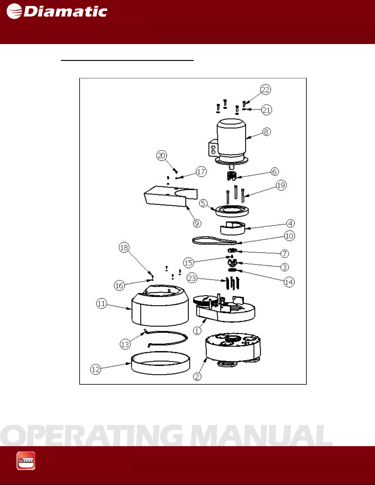
SECTION 10 SPARE PARTS
Upper & Lower Assemblies Combined
MODEL BMG-535 GRINDER
OPERATING MANUAL
APRIL 2009
Grinding & Polishing
70
Page 72
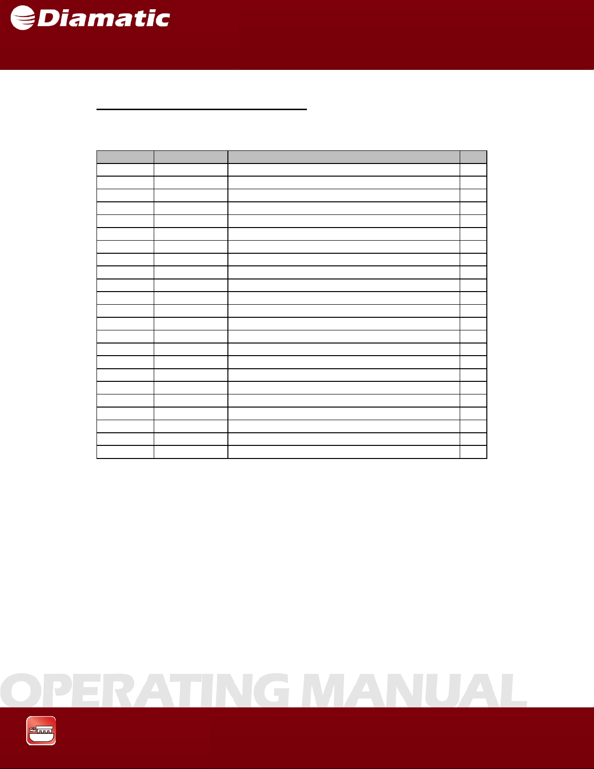
SECTION 10 SPARE PARTS
Upper & Lower Assemblies Combined
ITEM NO. PART NUMBER DESCRIPTION QTY.
1 PG-10297 UPPER ASSEM BLY 1
2 PG-10299 LOWER ASSEM BL Y 1
3 P A-10249 MA CHINED COUPLING 1
4 BG005311 MOTOR SEAT 1
5 BG005310 FLANGE, MOTOR SEAT 1
6 P A-10858 MOT O R CO UPLING 1
7 CP-10052 SPIDER 1
8 BG11960 MOTOR 1
9 BG005347 PROTECTION CAP 1
10 BG11924 UPPER DRIVE BELT 1
11 BG005539 COVER HOUSING 1
12 BG11925 DUST RING 1
13 PG-10309 WATER PIP E ASSEMBLY (OPTIONAL) 1
14 BG11797 SEAL 1
15 BG11780 KEY 1
16 800774 FLAT WASHE R, 6MM, NARROW 4
17 800775 FLAT WASHE R, 8MM, NARROW 2
18 800779 M6 X 1.0 X 16MM SOCKE T HEAD CAP SCREW 4
19 800830 M14 X 2.0 X 110MM SOCKET HEAD CAP SCREW 4
20 05-91578 M8 X 1.25 X 16MM HEX HEAD CAP SCREW, 2
21 5001090 FLAT WASHE R, 14MM 4
22 5036870 M14 X 2.0 X 40MM HEX HEAD CAP SCREW 4
23 800857 M8 X 1.25 X 90MM SOCKET HEAD CAP SCREW 6
MODEL BMG-535 GRINDER
OPERATING MANUAL
APRIL 2009
Grinding & Polishing
71
Page 73
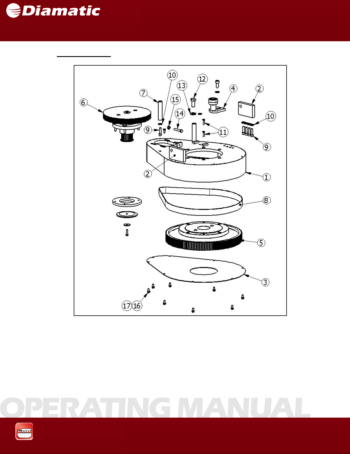
SECTION 10 SPARE PARTS
Upper Assembly
MODEL BMG-535 GRINDER
OPERATING MANUAL
APRIL 2009
Grinding & Polishing
72
Page 74
SECTION 10 SPARE PARTS
R
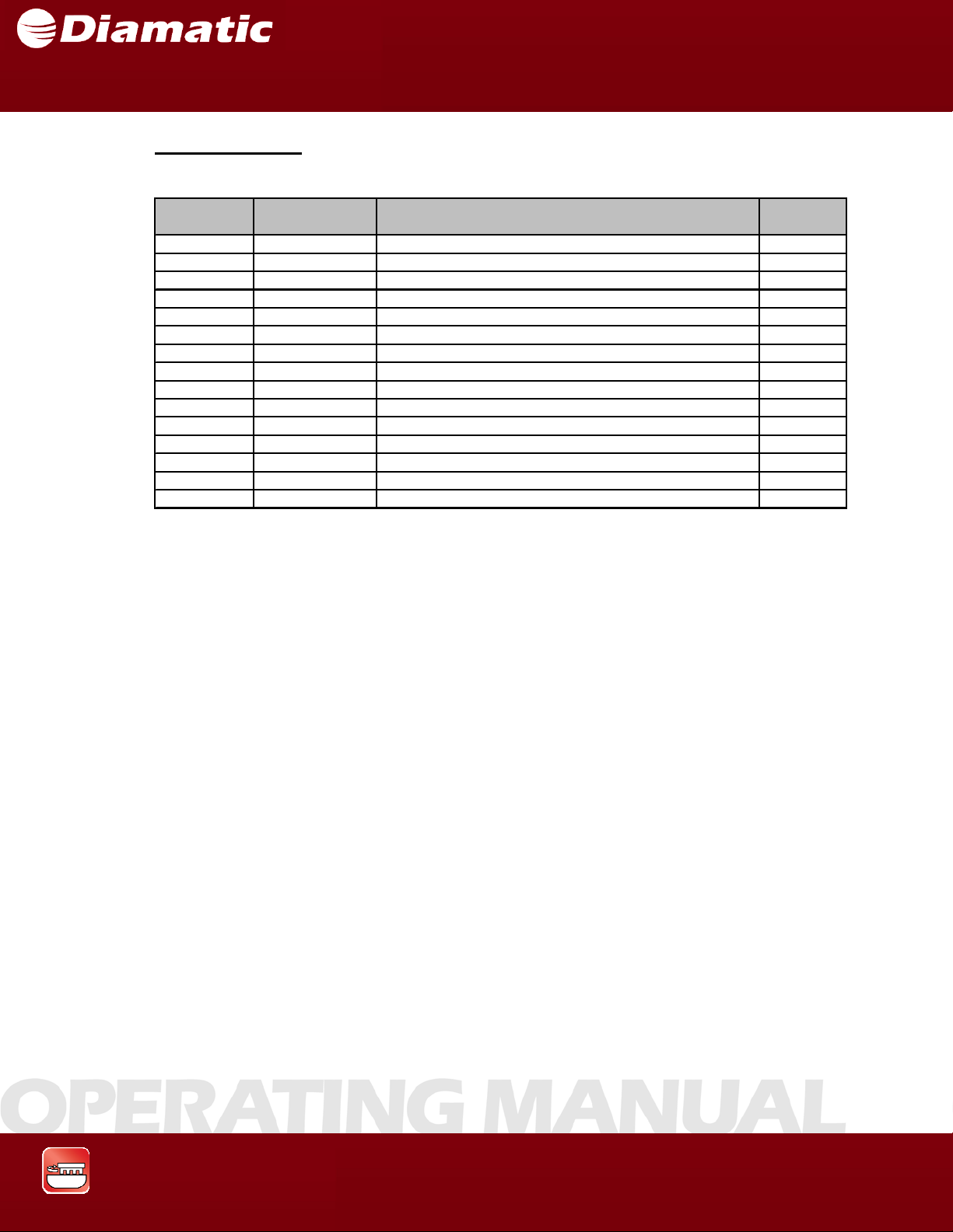
Upper Assembly
ITEM NO.
1 BG005309 MOTOR PLATE ASSEMBLY 1
2 BG005313 HOLDER 2
3 BG007834 LOWER P LA T E UP PER DRIVE 1
4 PG-10044 TENSIONER UPPER B ELT 1
5 PG-10300 CENTER PULLEY ASSEMBLY 1
6 PG-10301 CONTRA PULLEY ASSEMBLY 1
7 PA-10250 PROTECTION CAP SUPPORT 2
8 BG11904 MIDDLE B ELT 1
9 800787 M8 X 1.25 X 30MM SOCKET HEAD CAP SCREW 6
10 800775 FLAT WAS HE R, 8MM, NARROW 6
11 800789 M14 X 2.0 X 30MM HEX HEAD CAP SCREW 1
12 5001090 FLAT WASHER, 14MM 1
13 800788 M8 X 1.25 X 45MM HEX HEAD CAP SCREW 1
14 5028810 M8 X 1.25 HEX NUT 1
15 5028750 M6 X 1.0 X 15MM HEX HEAD CAP SCREW 1
PART
NUMBE
MODEL BMG-535 GRINDER
OPERATING MANUAL
APRIL 2009
DESCRIPTION QTY
Grinding & Polishing
73
Page 75
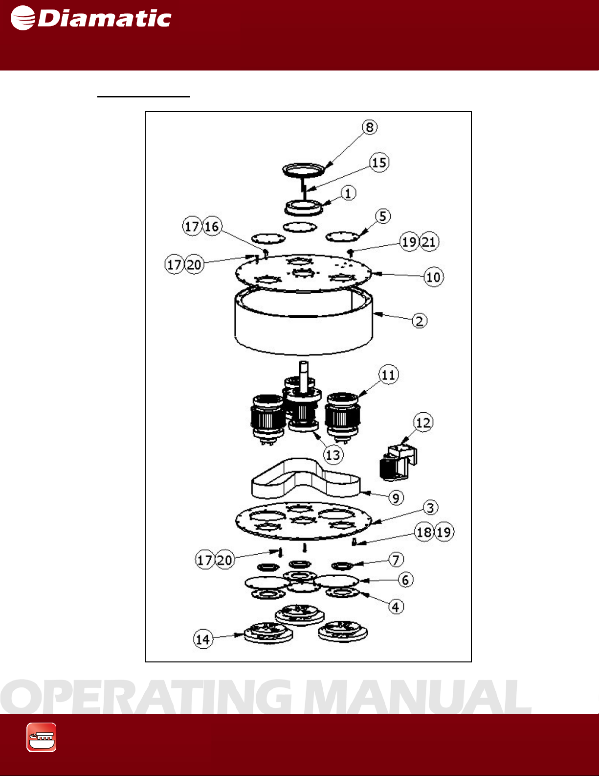
SECTION 10 SPARE PARTS
Lower Assembly
MODEL BMG-535 GRINDER
OPERATING MANUAL
APRIL 2009
Grinding & Polishing
74
Page 76
SECTION 10 SPARE PARTS
R
A
R
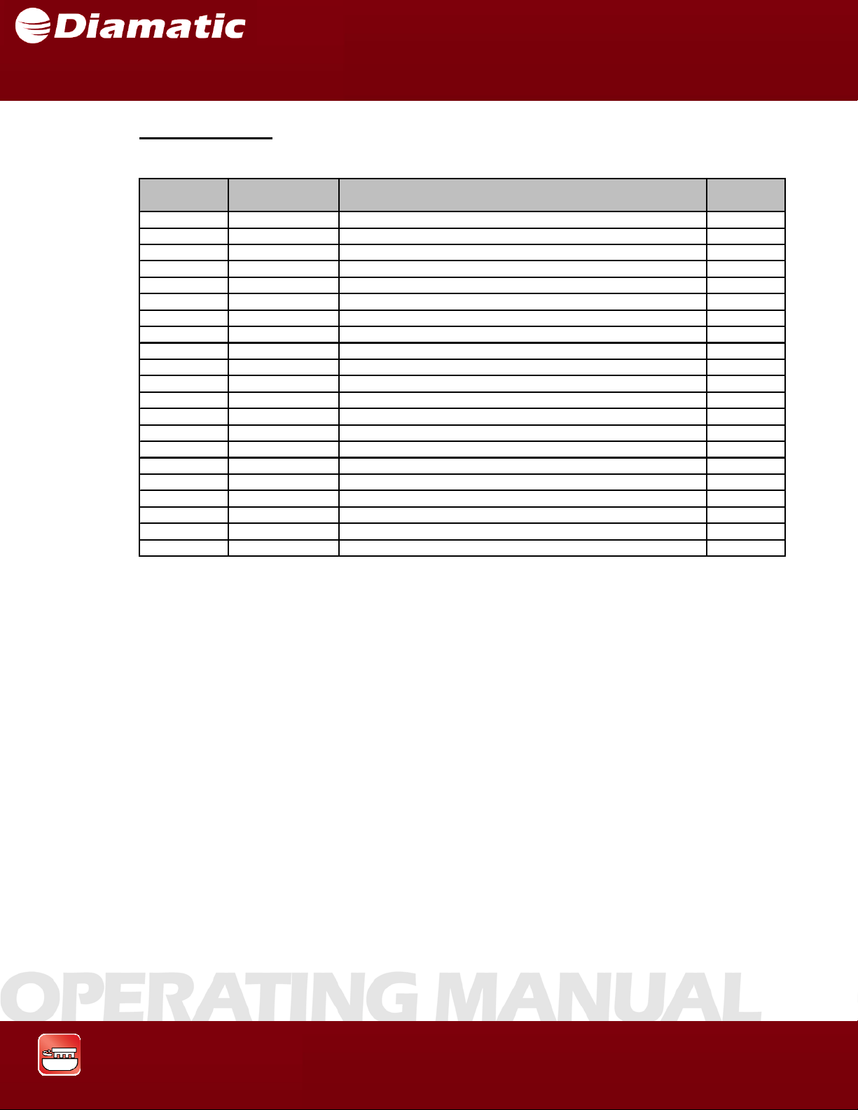
Lower Assembly
ITEM NO.
1 BG005314
2 BG005322 HOUSING 1
3 BG005324 LOWER P LA T E 1
4 BG005326 RING 3
5 BG005327 COVER 4
6 BG005350 INSPECTIO N COVE R 2
7 BG11829 V-RING SEAL 3
8 BG11849 V-RING SEAL 1
9 BG11928 LOWER BELT 1
10 PA-10845 UPPER PLATE 1
11 P G-10290 TOOLING DRIVE AXLE ASSEMBLY 3
12 P G-1 0291 LOWER TENSIONER ASSEMBLY 1
13 P G-1 0292 DRIVING P ULLE Y A SSEMBLY 1
14 P G-1 0293 DIAMOND HOLDE
15 800840 M6 X 1.0 X 50MM FLAT HEAD SOCKET CAP SCREW 2
16 5028 750 M6 X 1.0 X 15MM HEX HEAD CAP SCREW 36
17 5037600 LOCK WASHER, M6 78
18 05-91578 M8 X 1.25 X 16MM HEX HEAD CAP SCREW 6
19 800848 LOCK WASHE R, M8 10
20 800839 M6 X 1.0 X 25MM HEX HEAD CAP SCREW 42
21 800803 M8 X 1.25 X 20MM HEX HEAD CAP SCREW 4
PART
NUMBE
MODEL BMG-535 GRINDER
OPERATING MANUAL
APRIL 2009
DESCRIPTION QTY
DAPTER RING 1
3
Grinding & Polishing
75
Page 77
SECTION 10 SPARE PARTS
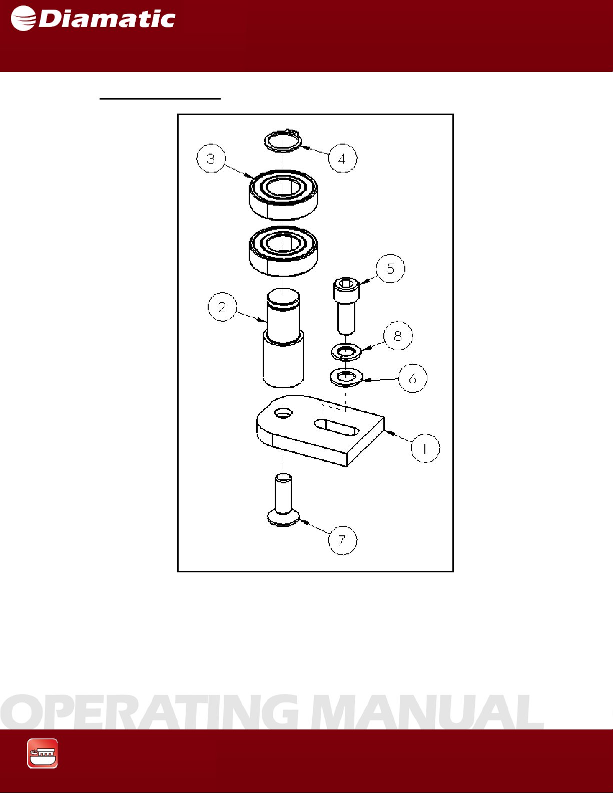
Upper Belt Tensioner
MODEL BMG-535 GRINDER
OPERATING MANUAL
APRIL 2009
Grinding & Polishing
76
Page 78
SECTION 10 SPARE PARTS
Upper Belt Tensioner
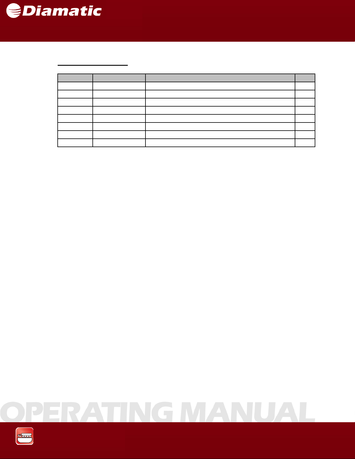
ITEM NO. PART NUMBER DESCRIPTION QTY.
1 BG005831 TENS ION PLATE 1
2 BG005830 AXLE 1
3 BG11911 BEARING 2
4 CP-10040 RETAINING RING, 20MM, EXT 1
5 800790 M10X1.5X30MM SOCKE T HEAD CAP SCREW 1
6 800791 FLAT WASHER, M10, NARROW 1
7 800792 M10 X 1.5 X 30MM FLAT HEAD SOCKET CA P S CRE W 1
8 4774800 LOCK WASHER, M10 1
MODEL BMG-535 GRINDER
OPERATING MANUAL
APRIL 2009
Grinding & Polishing
77
Page 79
SECTION 10 SPARE PARTS
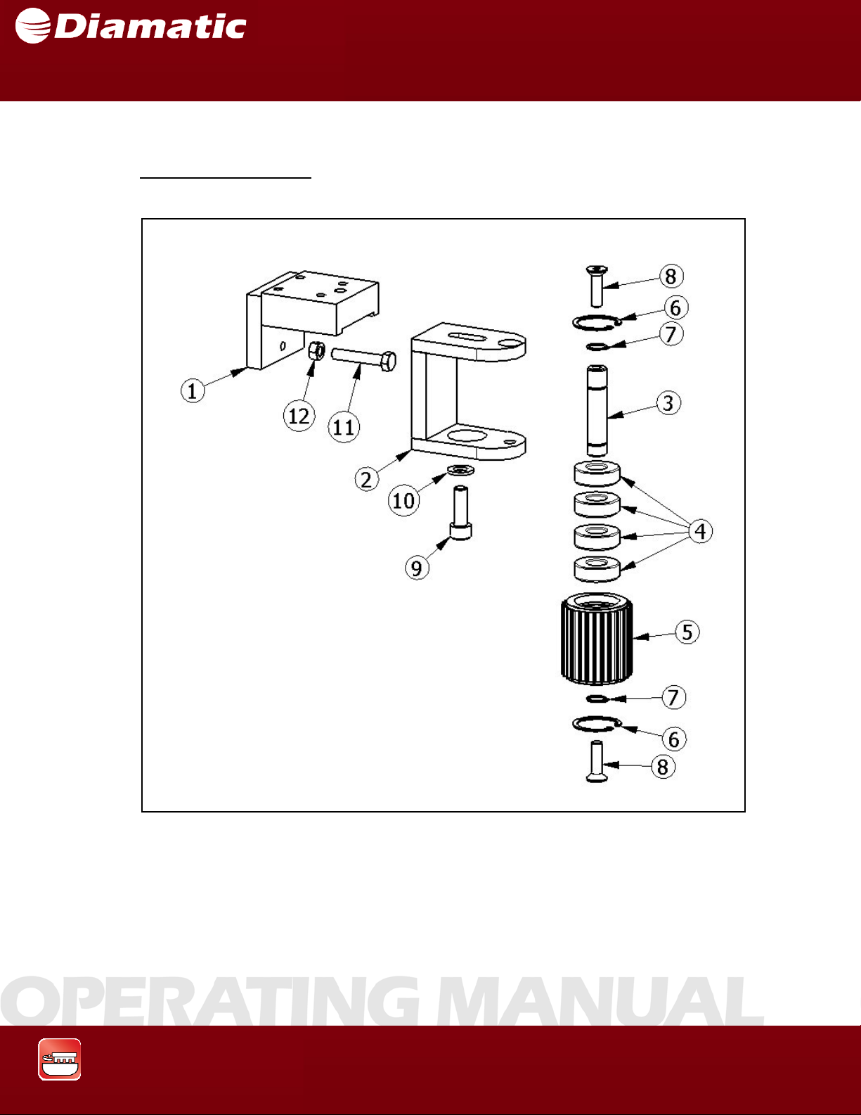
Lower Belt Tensioner
MODEL BMG-535 GRINDER
OPERATING MANUAL
APRIL 2009
Grinding & Polishing
78
Page 80
SECTION 10 SPARE PARTS
Lower Belt Tensioner
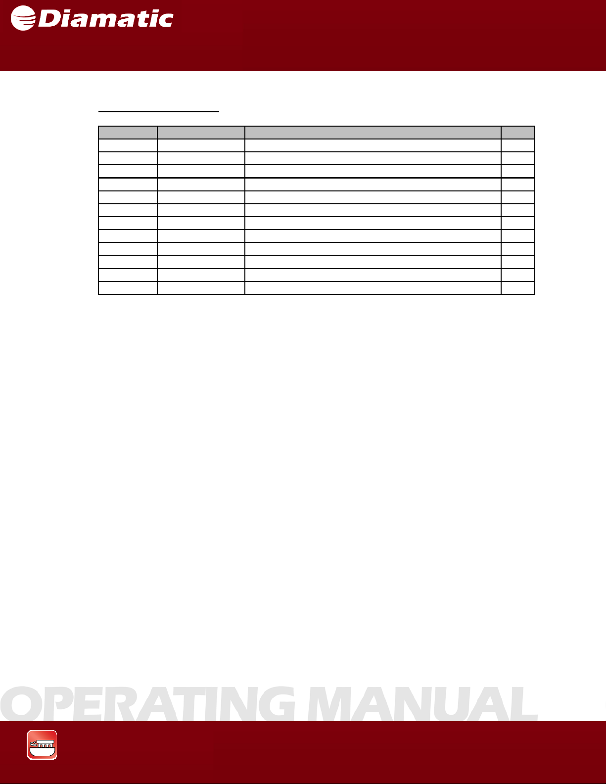
ITEM NO. PART NUMBER DESCRIPTION QTY
1 BG005332 HOLDER, LOWER BELT TENSIONE R 1
2 BG005333 TENSIONER, LOWER 1
3 BG005337 AXLE, LOWER TENSIONER 1
4 BG11792 BEARING 4
5 BG005336 PULLEY 1
6 BG11793 RETAINING RING, 35MM, INTERNAL 2
7 BG11794 RETAINING RING, 15MM, EXTERNAL 2
8 800785 M 8 X 1.25 X 30MM FLA T HE A D SOCKET CAP SCREW 2
9 800790 M 10 X 1.5 X 30MM SOCKET HEAD CAP SCREW 1
10 800791 FLAT WASHER, M10 1
11 800826 M8 X 1.25 X 50MM HEX HEAD CAP SCREW 1
12 5028810 M8 X 1.25 HEX NUT 1
MODEL BMG-535 GRINDER
OPERATING MANUAL
APRIL 2009
Grinding & Polishing
79
Page 81
SECTION 10 SPARE PARTS
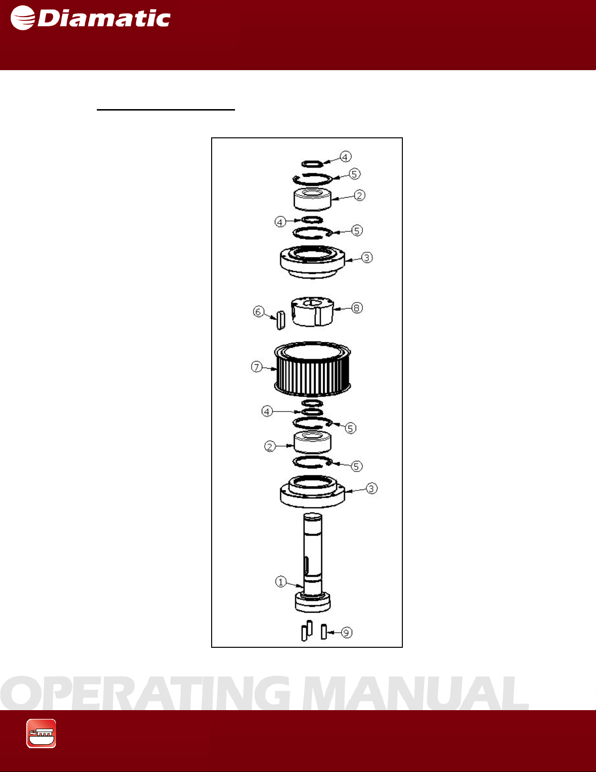
Tooling Pulley Assembly
MODEL BMG-535 GRINDER
OPERATING MANUAL
APRIL 2009
Grinding & Polishing
80
Page 82
SECTION 10 SPARE PARTS
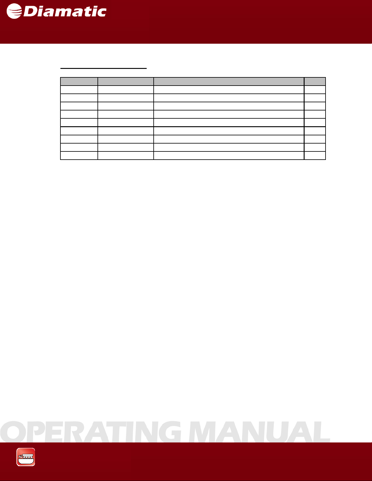
Tooling Pulley Assembly
ITEM NO. PART NUMBER DESCRIPTION QTY.
1 PA-10921 AXLE, TOOLING DRIVE, IMPERIAL 1
2 BG11817 BEARING 2
3 BG005317 BEARING HOUSE 2
4 BG11801 RETAINING RI NG, 30MM, EXTERNAL 4
5 BG11814 RETAINING RI NG, 62MM, INTERNAL 4
6 BG11780 KEY 1
7 PA-10924 PULLEY, IMPERIAL 1
8 BG11819 TAPER LOCK BUSHING 1
9 CP-10054 DOWEL PIN 3
MODEL BMG-535 GRINDER
OPERATING MANUAL
APRIL 2009
Grinding & Polishing
81
Page 83
SECTION 10 SPARE PARTS
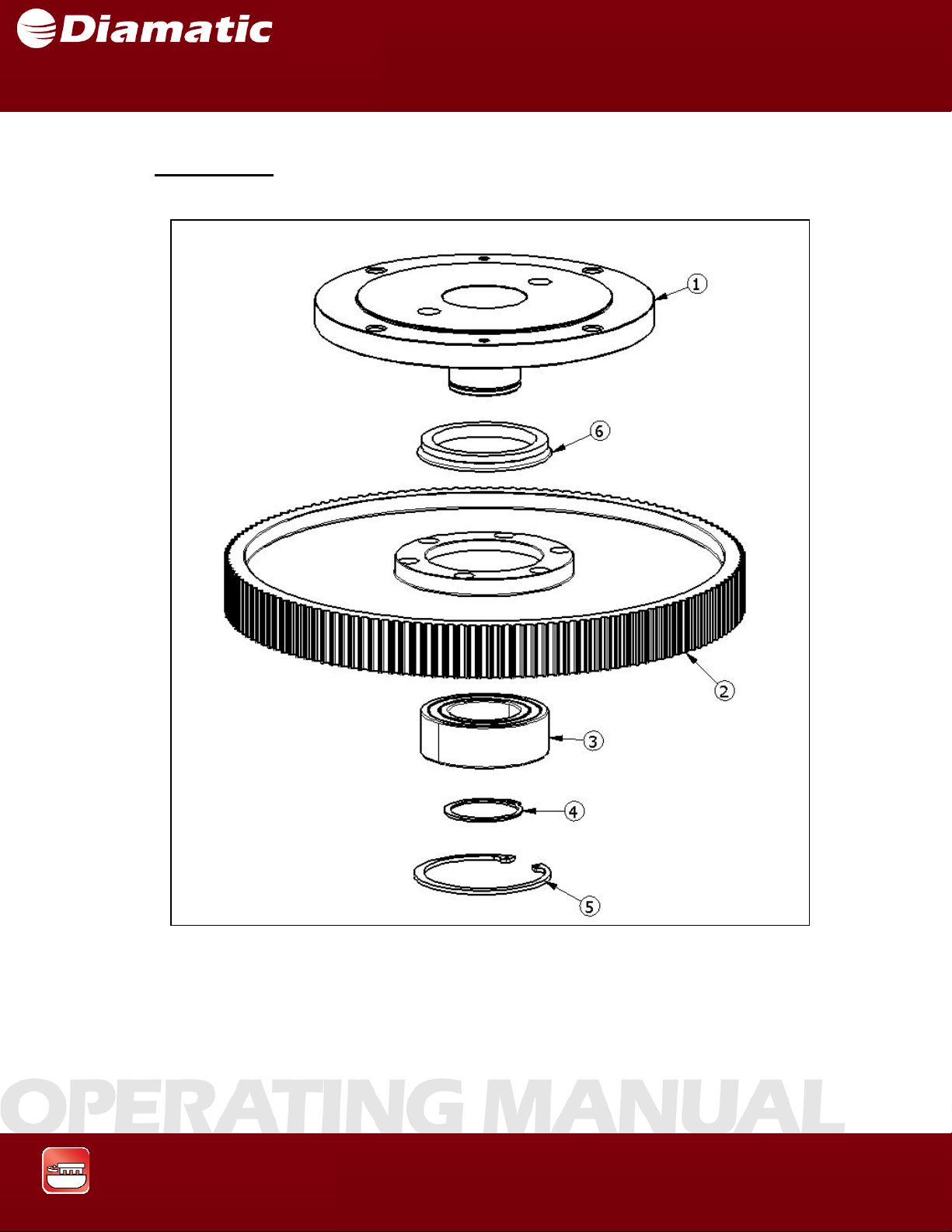
Center Pulley
MODEL BMG-535 GRINDER
OPERATING MANUAL
APRIL 2009
Grinding & Polishing
82
Page 84
SECTION 10 SPARE PARTS
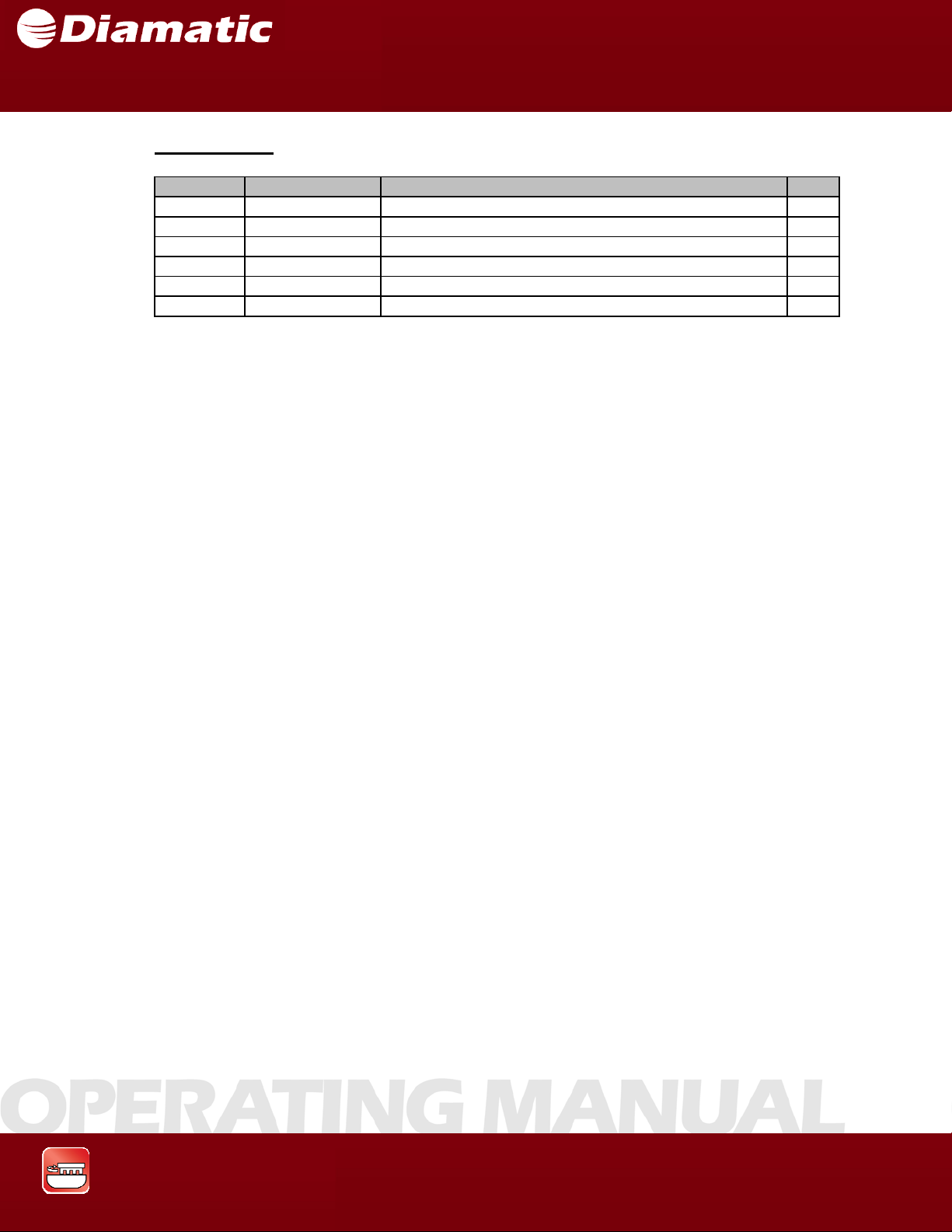
Center Pulley
ITEM NO. PART NUMBER DESCRIPTIO N QTY.
1 PA-10875 SPROCKET 1
2 BG005306 PULLEY 1
3 BG11984 BEARING 1
4 CP-10045 RETAINING RING, EXTERNAL, 50MM 1
5 CP-10044 RETAINING RING, INTERNAL, 90MM 1
6 CP-10053 V-SEAL 1
MODEL BMG-535 GRINDER
OPERATING MANUAL
APRIL 2009
Grinding & Polishing
83
Page 85
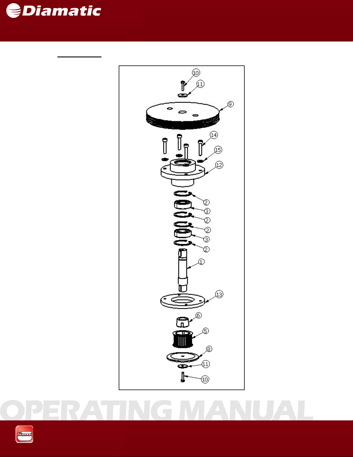
SECTION 10 SPARE PARTS
Contra pulley
MODEL BMG-535 GRINDER
OPERATING MANUAL
APRIL 2009
Grinding & Polishing
84
Page 86
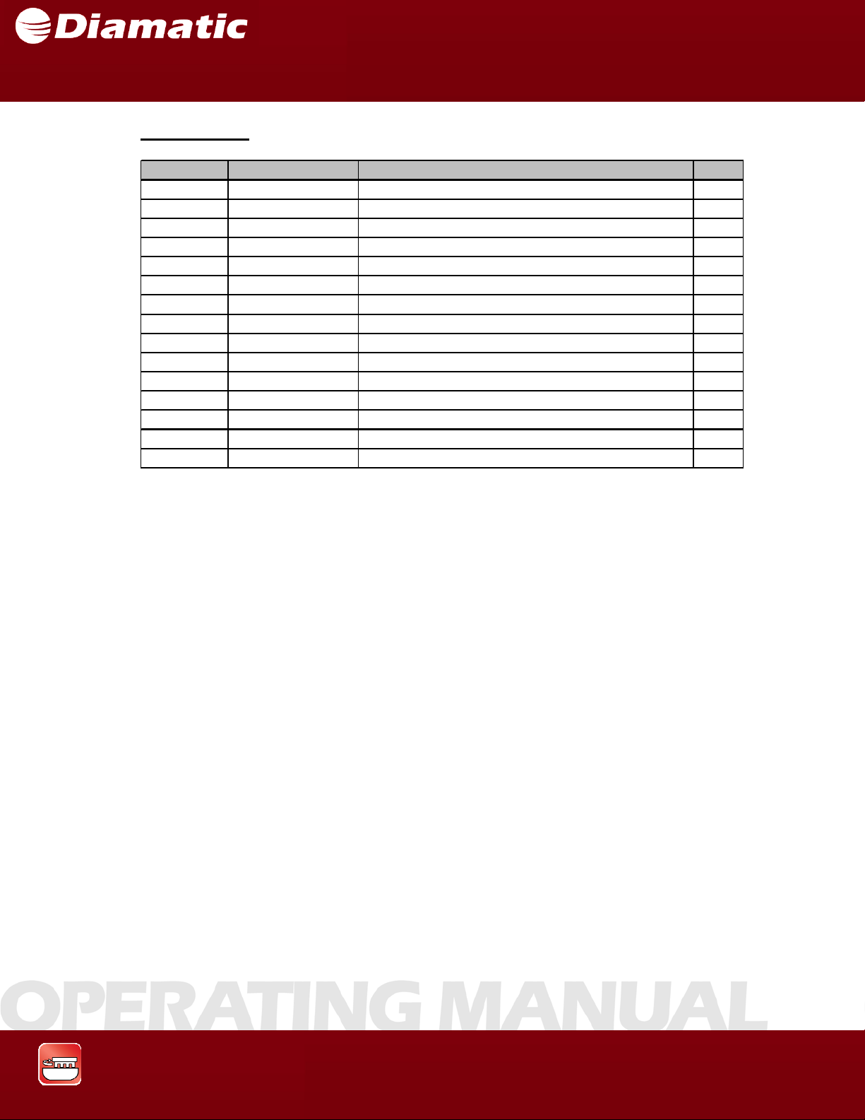
SECTION 10 SPARE PARTS
Contra Pulley
ITEM NO. PART NUMBER DESCRIPTION QTY.
1 BG005301 AXLE, CONTRA PULLEY 1
2 CP-10047 RETAINING RING, INTERNAL, 52MM 4
3 BG11881 BEARING 2
4 CP-10051 RETAINING RING, EXTERNAL, 25MM 1
5 PA-10928 PULLEY 1
6 CP-10280 BUSHI NG, TAPER LOCK 1
7 CP-10046 KEY 2
8 BG007804 FLANGE 1
9 BG007803 BELT PULLEY 1
10 800839 M6 X 1.0 X 25MM HEX HEAD CAP SCREW 2
11 800795 FLAT WASHE R, M6, EXTRA WIDE 2
12 BG007802 BEARING HOUSE 1
13 BG007807 RING 1
14 800796 M8 X 1.25 X 40MM SOCKET HEAD CAP SCREW 4
15 800775 FLAT WASHER, M8, NARROW 4
MODEL BMG-535 GRINDER
OPERATING MANUAL
APRIL 2009
Grinding & Polishing
85
Page 87
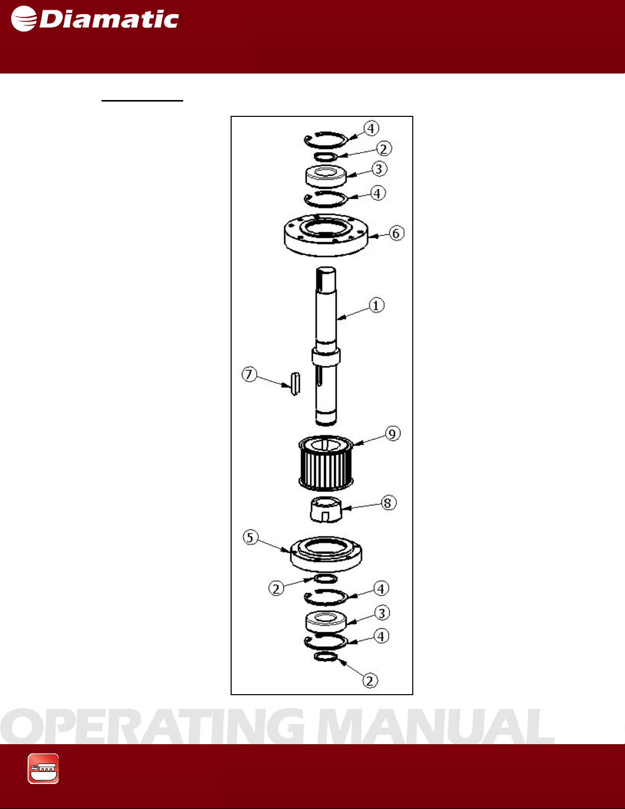
SECTION 10 SPARE PARTS
Driving Pulley
MODEL BMG-535 GRINDER
OPERATING MANUAL
APRIL 2009
Grinding & Polishing
86
Page 88
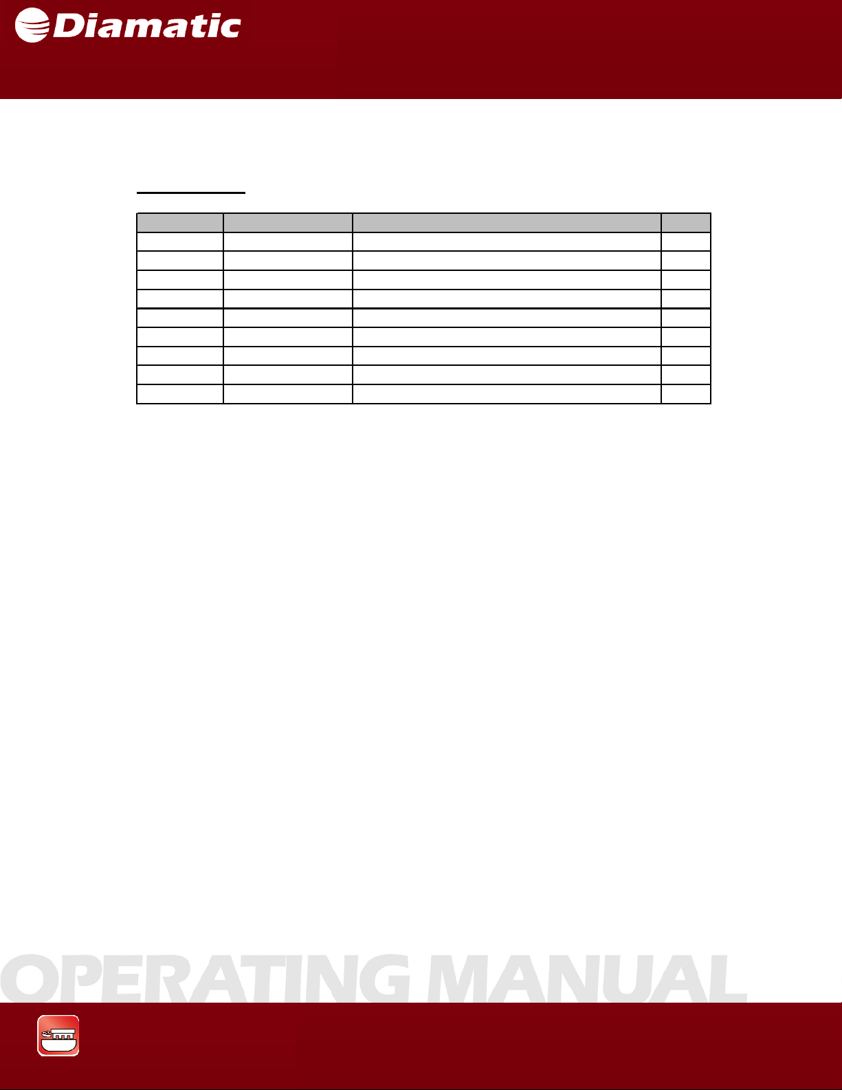
SECTION 10 SPARE PARTS
Driving pulley
ITEM NO . PART NUMBER DESCRIPTION QTY.
1 PA- 109 22 AXLE, DRIVING PULLEY, IMPERIAL 1
2 BG11801 RET RING, 30MM, EXTERNAL 3
3 BG11800 BEARING 2
4 BG11814 RET RING, 62MM, INTERNAL 4
5 BG005321 BEARING HOUS E 1
6 BG005315 BEARING HOUS E 1
7 BG11816 KEY 1
8 CP-10297 TAPER BUSHING 1
9 PA- 10923 P ULLE Y 1
MODEL BMG-535 GRINDER
OPERATING MANUAL
APRIL 2009
Grinding & Polishing
87
Page 89
SECTION 10 SPARE PARTS
Diamond Plate Holder
MODEL BMG-535 GRINDER
OPERATING MANUAL
APRIL 2009
Grinding & Polishing
88
Page 90
SECTION 10 SPARE PARTS
Diamond Plate Holder
ITEM NO. PART NUMBER DESCRIPTION Q T Y.
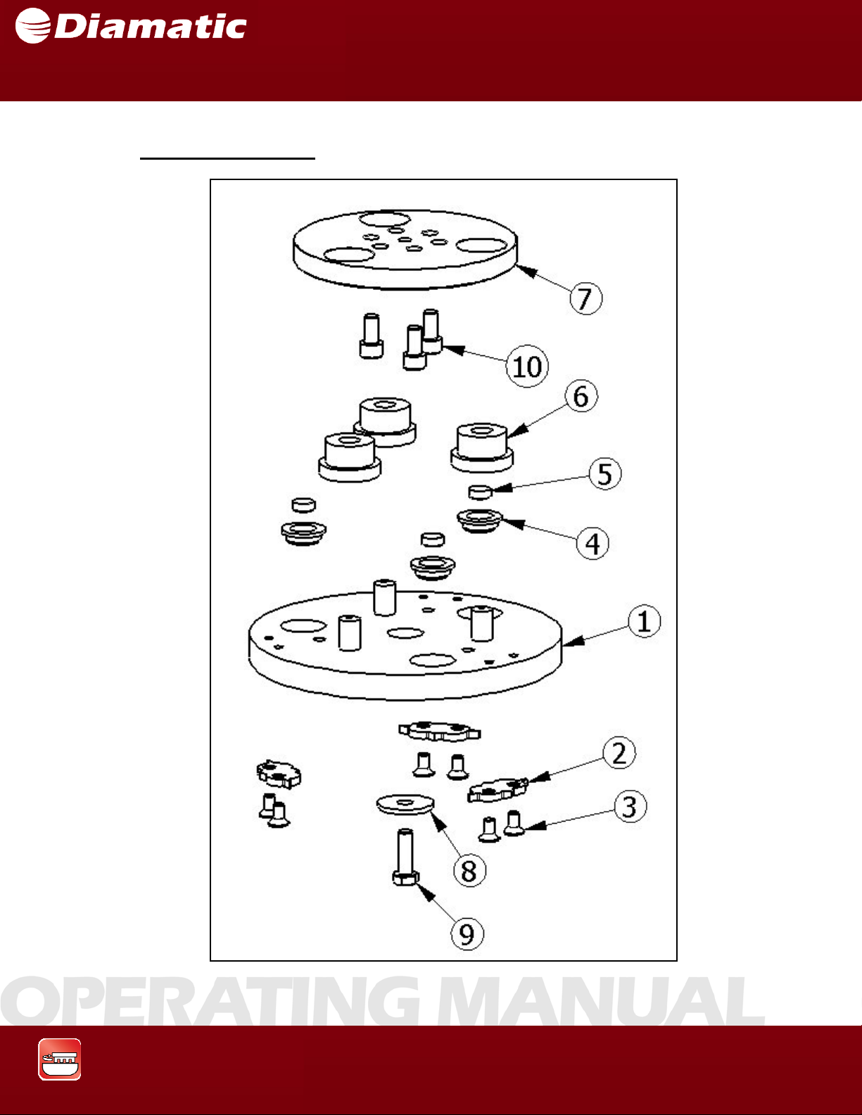
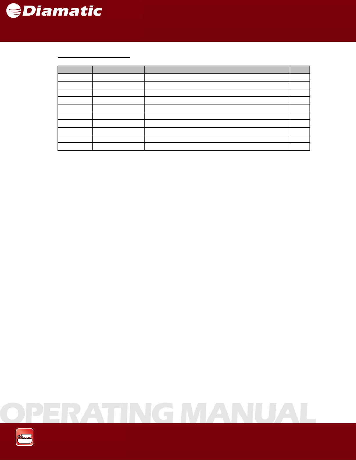
1 BG11809 TOOL HOLDER 1
2 BG11811 CENTERING STAR 3
3 800811 M6 X 1.0 X 12MM FLAT HEAD SOCKET CAP SCREW 6
4 BG11808 MAGNET HOLDER 3
5 BG11807 MAGNET 3
6 BG11806 BUFFER SOFT 3
7 BG11805 BUFFER PLATE 1
8 800827 W ASHER, FLAT, M8, WIDE 1
9 800828 M8 X 1.25 X 25MM HEX HEAD BOLT 1
10 80078 1 M8 X 1.25 X 15MM SOCKET HEAD CAP SCREW 3
MODEL BMG-535 GRINDER
OPERATING MANUAL
APRIL 2009
Grinding & Polishing
89
 Loading...