

Page 1
User Guide
DA7212 User Guide – Rev1.2
MIC1_P/
DMICCLK
ADC L
ADC
DIGITAL
FILTERS
Wind Noise
Filtering,
Automatic
Level Control
(ALC)
DAC
DIGITAL
FILTERS
Digital Mixer,
Digital
Volume,
5 Band
Equaliser,
Noise Gate
DAC L
AUX_L
AUX_R
FM
Radio
SP_P
PLL
+
INL_PGA
MIC2_P
+
INR
_PGA
ADC R
DAC R
+
+
GND_CP
BCLK
DATOUT
WCLK
DATIN
DIGITAL AUDIO
INTERFACE (DAI)
SP_N
Speaker
Charge
Pump
HPCSP
HPCSN
1uF
1uF
VDIG
VMID
GND_A
Headphones
HP L
HP R
HP_L
HP_R
CONTROL
INTERFACE
SDA
SCLK
1µF
HPCFN
HPCFP
1uF
DACREF
BIAS
MIC1
_PGA
MIC2
_PGA
MIC1_N/
DMICIN
MICBIAS1
MICBIAS2
MIC2_N
MCLK
GND_SENSE
VDD_SP
VREF
MIC
BIAS1
MIC
BIAS2
1µF
AUXL
_PGA
AUX2
_PGA
DA7212
VDD_CP
VDD_MIC
BEEP
GENERATOR
+
VDD_IO
VDD_A
LDO
DA7212 Ultra Low Power Codec
and
Power Commander™ GUI Software
Introduction
The DA7212 Evaluation Board has been designed to allow measurement and
evaluation of the DA7212 device.
All Audio Codec functionalities are self-contained within the Evaluation Board
(EVB).
The EVB is supplied with a USB memory stick containing various documents
and a GUI to allow the user to control the DA7212.
The GUI is called Power Commander™. It uses a simple graphical interface,
allowing the DA7212 to be controlled via a USB port of a PC.
The EVB has a number of jumper links to enable the user to change the
system configuration and to allow him to make appropriate measurements,
although, in reality, few jumper links are required to be altered for standard
operations of the DA7212.
User Guide DA7212_Rev1v2 CONFIDENTIAL Page 1 of 34
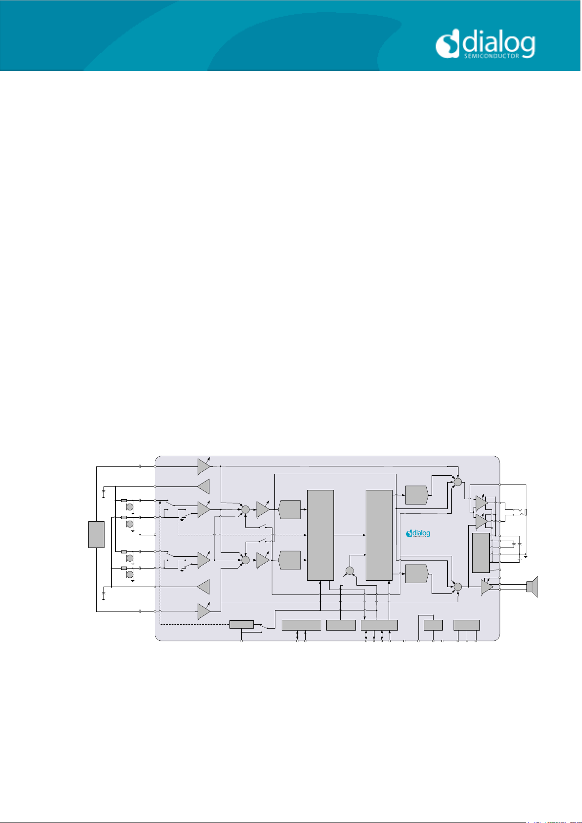
Figure :1 DA7212 Block Diagram
Page 2

User Guide
DA7212 User Guide – Rev1.2
Table of Contents
SUMMARY 3
HARDWARE 4
Power Supplies 6
Audio Connections 7
Jumpers Link Positions and Button Settings 8
CONTROL SOFTWARE 11
Installation 11
Control Panel 13
Status and Controls 14
Control Interface 17
Codec Config Page 18
DAI and PLL Page 19
Analogue Inputs 20
Analogue Outputs 21
Mixers 22
ADC Control 23
DAC Control 24
ALC Control 25
Tone Gen 26
Codec Registers 27
TROUBLESHOOTING 28
Software Issues 28
Hardware Issues 28
APPENDIX A – REGISTER TEXT FILE 30
APPENDIX A – SOCKETED MINIBOARD (169-01-A) 33
REVISION HISTORY 34
User Guide DA7212_Rev1v2 CONFIDENTIAL Page 2 of 34
Page 3

User Guide
DA7212 User Guide – Rev1.2
Summary
This document provides some useful information to the user about the EVB
and the GUI to allow testing and evaluation of the DA7212 Ultra Low Power
Codec.
The hardware solution is based upon two PCBs:
- “EVALUATION MOTHERBOARD 170-03-A”
- “CUSTOMER REFERENCE BOARD 169-02-A” (DA7212 mini board)
The GUI, called Power Commander™, requires a PC operating Windows
2000/XP/Vista/Windows 7 with a USB1.1 or USB2 interface.
To run Power Commander™ under Windows Vista, set the default installation
location to „C:\Dialog Semiconductor\‟.
Note that Dialog recommends connecting the EVB to a 500 mA capable USB
port as we cannot guarantee that a USB hub (set to 100 mA) is sufficient to
operate it correctly.
See the section on Power Supplies below.
The GUI allows the user to: (i) configure the DA7212 using one of the several
pre-loaded initialisation files (i.e. start-up sequences) available; (ii) write and
read operations to all control registers; and (iii) monitor of device status.
User Guide DA7212_Rev1v2 CONFIDENTIAL Page 3 of 34
Page 4
User Guide
DA7212 User Guide – Rev1.2
Hardware
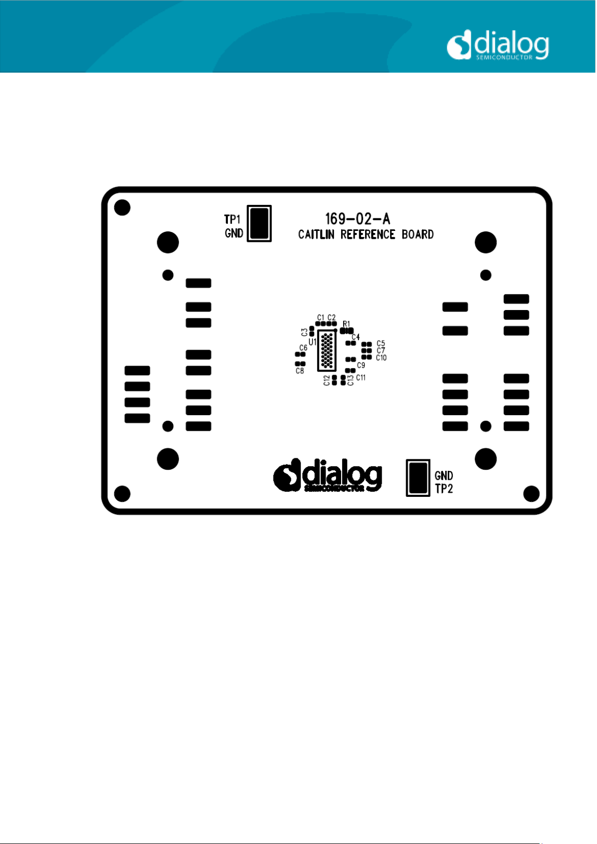
The DA7212 Evaluation Board consists of two boards:
A daughterboard containing the DA7212, and the essential external
components. This board could also be used in standalone or as a module for
a customer development platform.
Figure 2: DA7212 Mini Board
Note a socketed mini board (169-01-A) is also available. See appendix B for
more information.
A motherboard containing many circuit blocks that allows for flexible
configuration and provides test access to the DA7212. It includes:
a. USB Interface with Control Interface level shifters
b. 1x audio optical input/output interfaces (with selection matrix)
c. USB reset and 3.3V reset switches
d. headphone output
e. line out outputs
f. auxiliary inputs
g. analogue/digital microphone inputs
h. master clock input
i. power supply inputs (VBAT, GND)
User Guide DA7212_Rev1v2 CONFIDENTIAL Page 4 of 34
Page 5
User Guide
DA7212 User Guide – Rev1.2
A USB-I2C bridge is used for communication with the device, and there are a
number of external active components to reduce the requirement for external
circuitry.
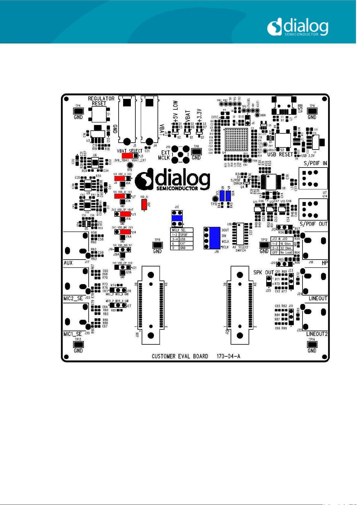
Figure 3: Mother Board – Default Jumper positions shown in Red (power) and Blue (signal)
Note: The EVB has been configured by default to work from the mother
board‟s on-board regulators.
User Guide DA7212_Rev1v2 CONFIDENTIAL Page 5 of 34
Page 6
User Guide
DA7212 User Guide – Rev1.2
Power Supplies
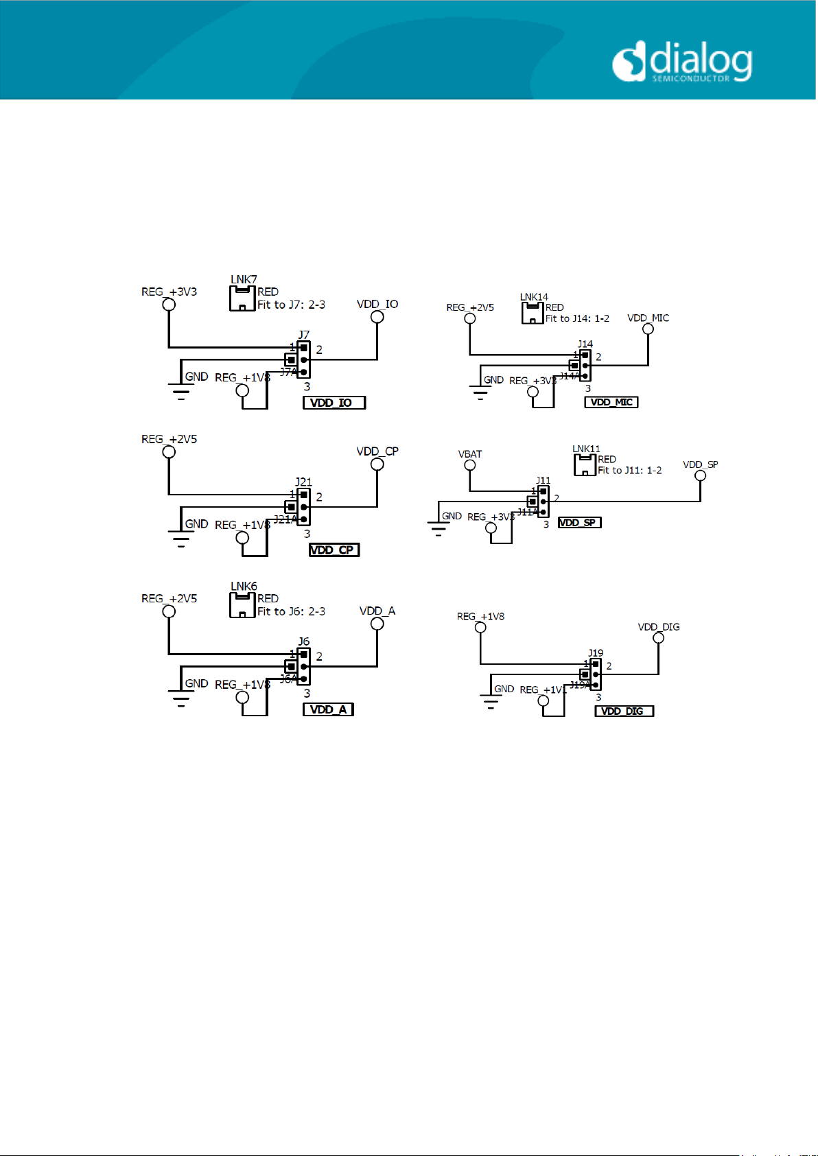
The DA7212 EVB is powered when a USB cable is connected to J1
(+5V_USB). With default jumper settings (J6, J7, J11, J14 and J19, J21), the
DA7212 device on the daughterboard is powered form the on-board
regulators.
As DA7212 supports a wide supply range the jumper configuration allows the
user to select one of two on-board supplies for each supply by connecting the
jumper link between pins 1&2 or 2&3 of the jumper. For maximum flexibility
the jumper link can be removed and a voltage can be supplied directly onto
pin 2 of the jumper with a ground connection connected to the A pin of the
jumper. Current measurements on individual supplies can also be performed
by connecting an ammeter between the supply and pin2 of the jumper.
Note: As VDD_IO supplies the IO voltage for the USB interface and level
translators jumper J10 has been provided for current measurements on this
supply of the DA7212 device. For current measurements on VDD_IO remove
the jumper link and insert an ammeter between pins 1 & 2 of J10.
Note: VDD_CP and VDD_DIG are not used in DA7212 and the jumper link
should be left unpopulated.
User Guide DA7212_Rev1v2 CONFIDENTIAL Page 6 of 34
Page 7
User Guide
DA7212 User Guide – Rev1.2
Connector
Name
Function
J17
AUX
Stereo single-ended auxiliary input
J30
MIC1_SE
Stereo single-ended microphone input
(connects to MIC1_P and MIC2_P)
J22
MIC2_SE
Stereo single-ended microphone input
(connects to MIC1_N and MIC2_N)
J26
Mono differential microphone input
Pin 1: MIC1_P
Pin 2: MIC1_N
Pin 3: GND
J27
Mono differential microphone input
Pin 1: MIC2_P
Pin 2: MIC2_N
Pin 3: GND
U7
S/PDIF IN
Digital optical input
U14
S/PDIF OUT
Digital optical output
J18
HP
Stereo single-ended headphone output
J24
LINEOUT
Differential line output (AC coupled,
use J25 for speaker)
J23
Differential line output (AC coupled,
use J25 for speaker)
Pin 1: LINE_P
Pin 2: GND
Pin 3: LINE_N
J25
Differential speaker output (DC
coupled)
Pin 1: SP_P
Pin 2: SP_N
J32
LINEOUT2
Unused
J31
Unused
Audio Connections
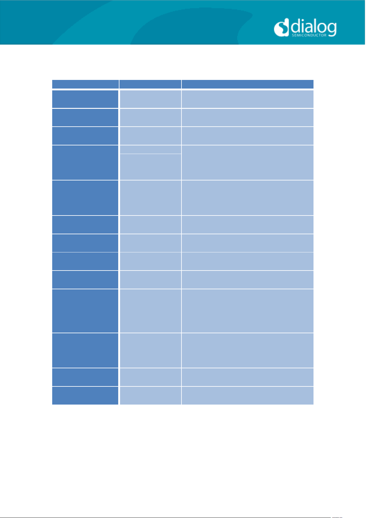
Table 1 170-04-A Audio Connectors
User Guide DA7212_Rev1v2 CONFIDENTIAL Page 7 of 34
Page 8
User Guide
DA7212 User Guide – Rev1.2
Jumper number
Position
Function
J3 &J4
External VBAT and GND
connection
J5
1-2, (default)
VBAT select: VBAT is
generated from an on-board
regulator supplied from the
USB
2-3
VBAT select: VBAT is
supplied from J3&J4
J6
1-2, (default)
Connects VDD_A from
onboard 1.8V supply
2-3
Connects VDD_A from
onboard 2.5V supply
A
GND connection for
connecting external supply
between pin 2 and A
J7
1-2, (default)
Connects VDD_IO from
onboard 1.8V supply
2-3
Connects VDD_IO from
onboard 3.3V supply
A
GND connection for
connecting external supply
between pin 2 and A
J8
On, (default)
Connects USB I2C SCLK to
device
J9
On, (default)
Connects USB I2C SDATA to
device
J10
On, (default)
Connects VDD_IO to the
DA7212 device.
J11
1-2
Connects VDD_SP from
onboard 3.3V supply
2-3, (default)
Connects VDD_SP from
VBAT
A
GND connection for
connecting external supply
between pin 2 and A
J12
1-2
MCLK comes from the SPDIF
interface
3-4, (default)
MCLK comes from the USB
interface
5
GND pin
6
External MCLK pin,
anexternal MCLK can be
connected between pins 5
Jumpers Link Positions and Button Settings
User Guide DA7212_Rev1v2 CONFIDENTIAL Page 8 of 34
Page 9
User Guide
DA7212 User Guide – Rev1.2
and 6.
J13
1-2
Inserts a 16ohm load across
the left headphone output
for test purposes
2-3
Inserts a 32ohm load across
the left headphone output
for test purposes
J14
1-2
Connects VDD_MIC from
onboard 3.3V supply
2-3, (default)
Connects VDD_MIC from
onboard 2.5V supply
A
GND connection for
connecting external supply
between pin 2 and A
J15
Allows connection of an
external MCLK using an SMB
connector. J12 should have
it’s jumper link removed
when using this option.
J16
1-2, (default)
Connects the SPDIF/USB
BCLK to the DA7212 device
3
GND for connecting BCLK
to/from an external source
between 2-3 (for example
Audio Precision PSIA cable)
4-5, (default)
Connects the SPDIF/USB
WCLK to the DA7212 device
6
GND for connecting WCLK
to/from an external source
between 5-6 (for example
Audio Precision PSIA cable)
7-8, (default)
Connects the SPDIF/USB
DIN to the DA7212 device
9
GND for connecting DIN
from an external source
between 8-9 (for example
Audio Precision PSIA cable)
10-11, (default)
Connects the SPDIF/USB
WCLK to the DA7212 device
12
GND for connecting DOUT to
an external source between
11-12 (for example Audio
Precision PSIA cable)
J19
1-2
Not Used
Do not connect for DA7212
2-3,
A
J20
1-2
Inserts a 16ohm load across
User Guide DA7212_Rev1v2 CONFIDENTIAL Page 9 of 34
Page 10
User Guide
DA7212 User Guide – Rev1.2
the right headphone output
for test purposes
2-3
Inserts a 32ohm load across
the right headphone output
for test purposes
J21
1-2, (default)
Not Used
Do not connect for DA7212
2-3
A
S1 Regulator Reset button:
Resets the 3.3V, 2.5V, 1.8V
and 1.1V regulators
S2 USB Reset button:
Resets the USB sub system
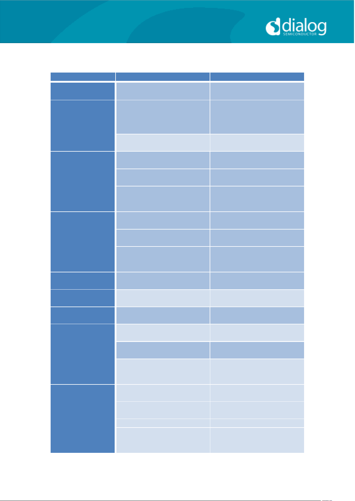
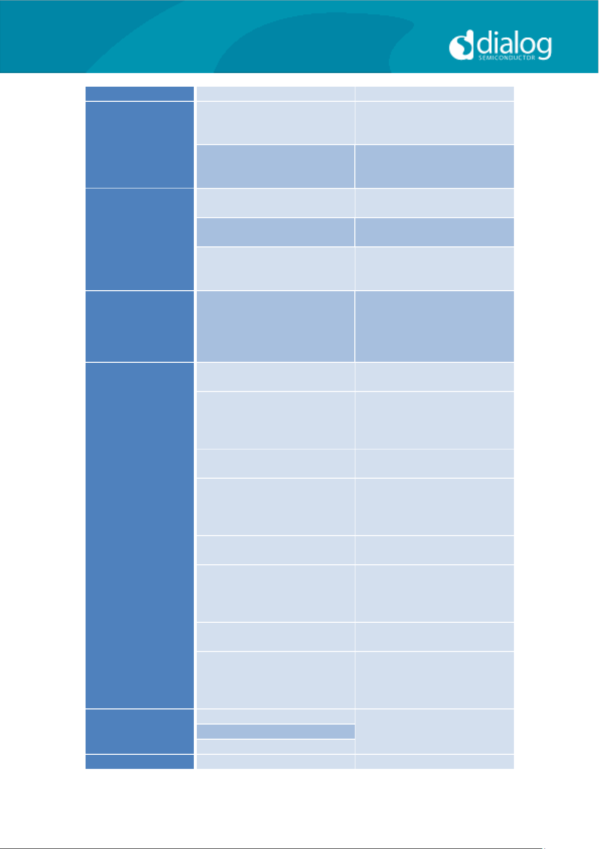
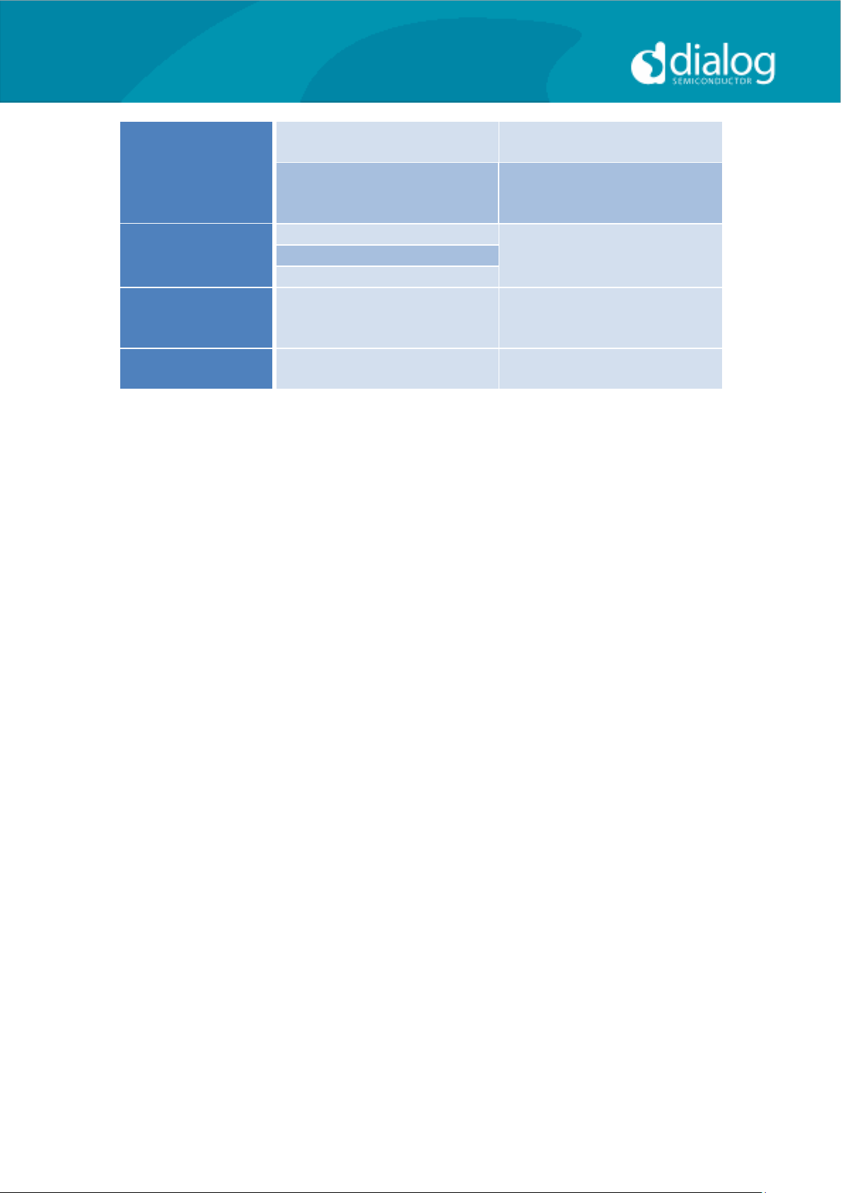
Table 2: 170-04-A Jumpers Link Positions and Button Settings
User Guide DA7212_Rev1v2 CONFIDENTIAL Page 10 of 34
Page 11
User Guide
DA7212 User Guide – Rev1.2
Control Software
Installation
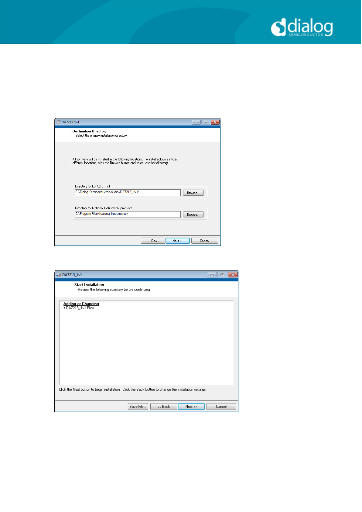
From the USB memory stick provided with the EVB box, run the „setup.exe‟
file (DA7212_USB\DA7212 GUI\setup.exe).
Click “Next>>”.
Click “Next>>”.
User Guide DA7212_Rev1v2 CONFIDENTIAL Page 11 of 34
Page 12
User Guide
DA7212 User Guide – Rev1.2
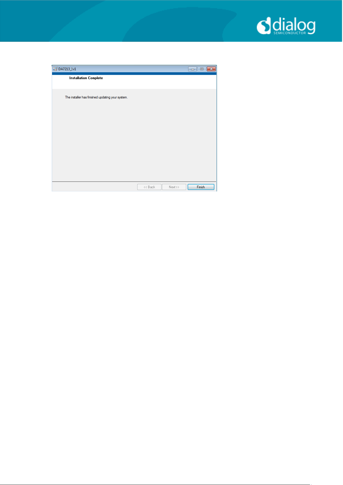
Click “Finish”.
You may need to restart your computer; in this case a pop up window will
appear asking you to do so.
Once your computer has restarted, plug the USB cable to the EVB and
Windows should detect the USB device and automatically install the driver. If
not, the driver is located on this DA7212 USB stick
User Guide DA7212_Rev1v2 CONFIDENTIAL Page 12 of 34
Page 13
User Guide
DA7212 User Guide – Rev1.2
Control Panel
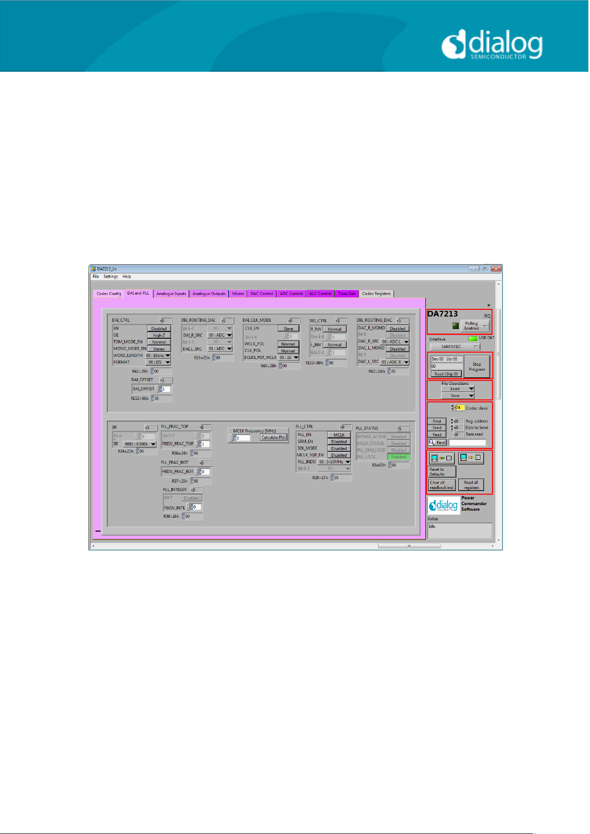
Run the DA7212 program by clicking the shortcut on the appropriate item in
the Start menu. The best setting for the PC display size is 1024x768 pixels or
above. Font size on the PC display should be Normal (95dpi). It is important to
note that a display size other than the recommended setting may affect the
way in which the panels appear.
The following screen appears, with the “USB OK?” LED lit if the USB interface
is correctly connected and operational.
To start the device, plug in the USB cable.
Figure 4 Initial Interface
If the Reset LED is blinking yellow, it indicates that the device is not yet
communicating via the I2C interface. See Troubleshooting for more details.
User Guide DA7212_Rev1v2 CONFIDENTIAL Page 13 of 34
Page 14
User Guide
DA7212 User Guide – Rev1.2
Status and Controls
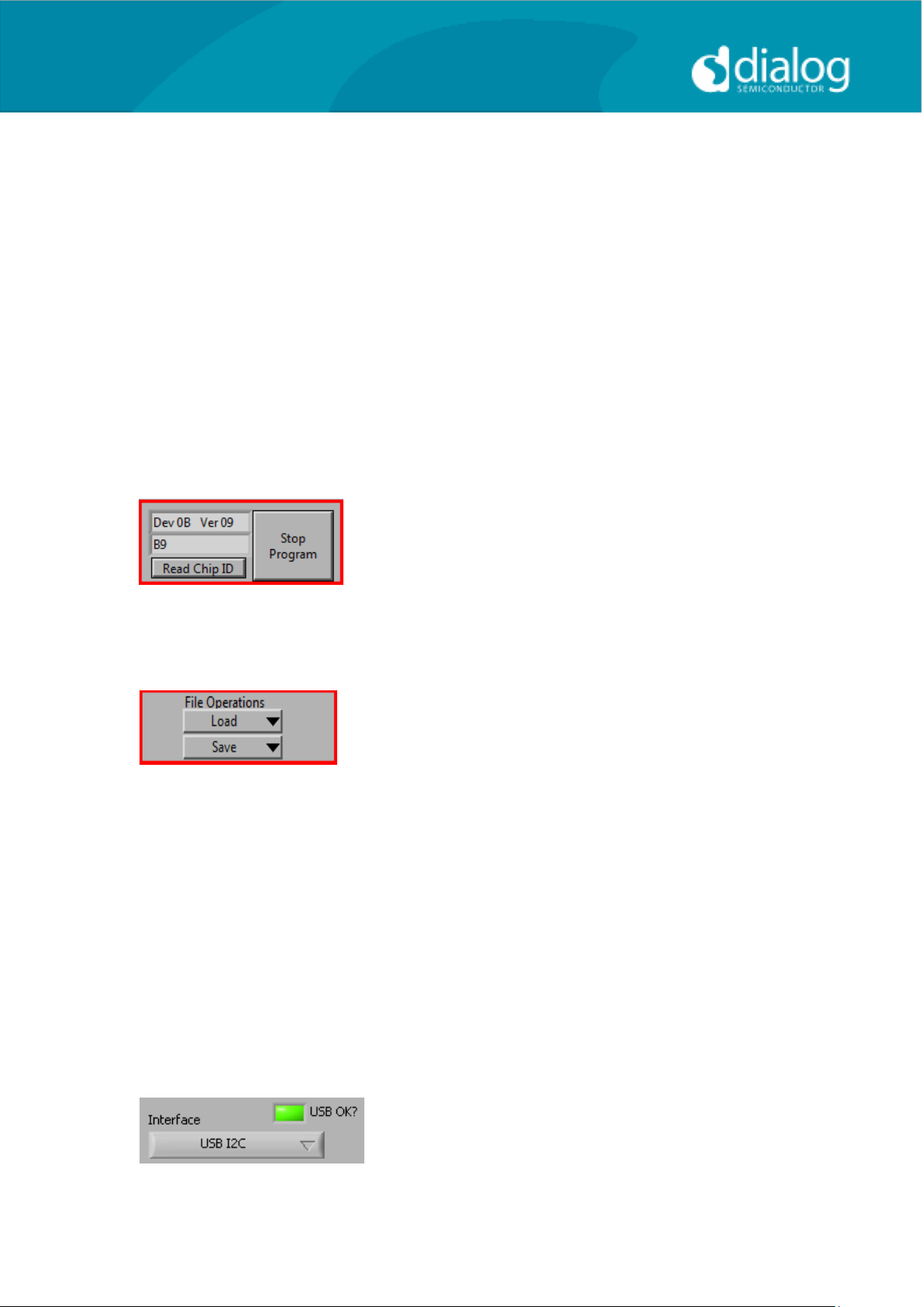
Polling Enabled BY default the current page contents is updated via
polling the I2C interface. If disabled, these readbacks
are suppressed. This is used to force the
communication over the bus to be silent.
If this is set to automatic, the program will only poll the
device while the application is the topmost window. If
obscured by another program or window, polling will
be disabled.
LED If the device is active this LED is green, or red if
inactive.
This indicates the device version when the device
is active. When inactive, version status will not be
correct.
Stop Program This terminates the program. If there are unsaved
changes, a dialog box is displayed.
Load Loads previously saved text files, send all
Registers and read back all registers.
“Load” opens a dialog box to select, view, copy or
re-name a file.
Load Codec file opens a dialog box to allow selection of a
codec setup file in the “\Codec Setups” directory.
Save Saves current panel state to a text file. Selecting
“Save Codec file..” saves the codec registers in a slightly
different format. Selecting “Register Dump” option saves
current register values to the text file. See Appendix A.
Note: Difference between “Save” and “Register Dump” is that the “Save”
dumps the contents of all panel controls to the file (a save state operation);
whereas, “Register Dump” reads the device contents (including status
registers) into the file. Note that some codec registers do not have readback
capability.
Interface Selects between USB I2C control
and offline mode. Switching to offline,
then back to USB reinitialises the
USB interface.
User Guide DA7212_Rev1v2 CONFIDENTIAL Page 14 of 34
Page 15
User Guide
DA7212 User Guide – Rev1.2
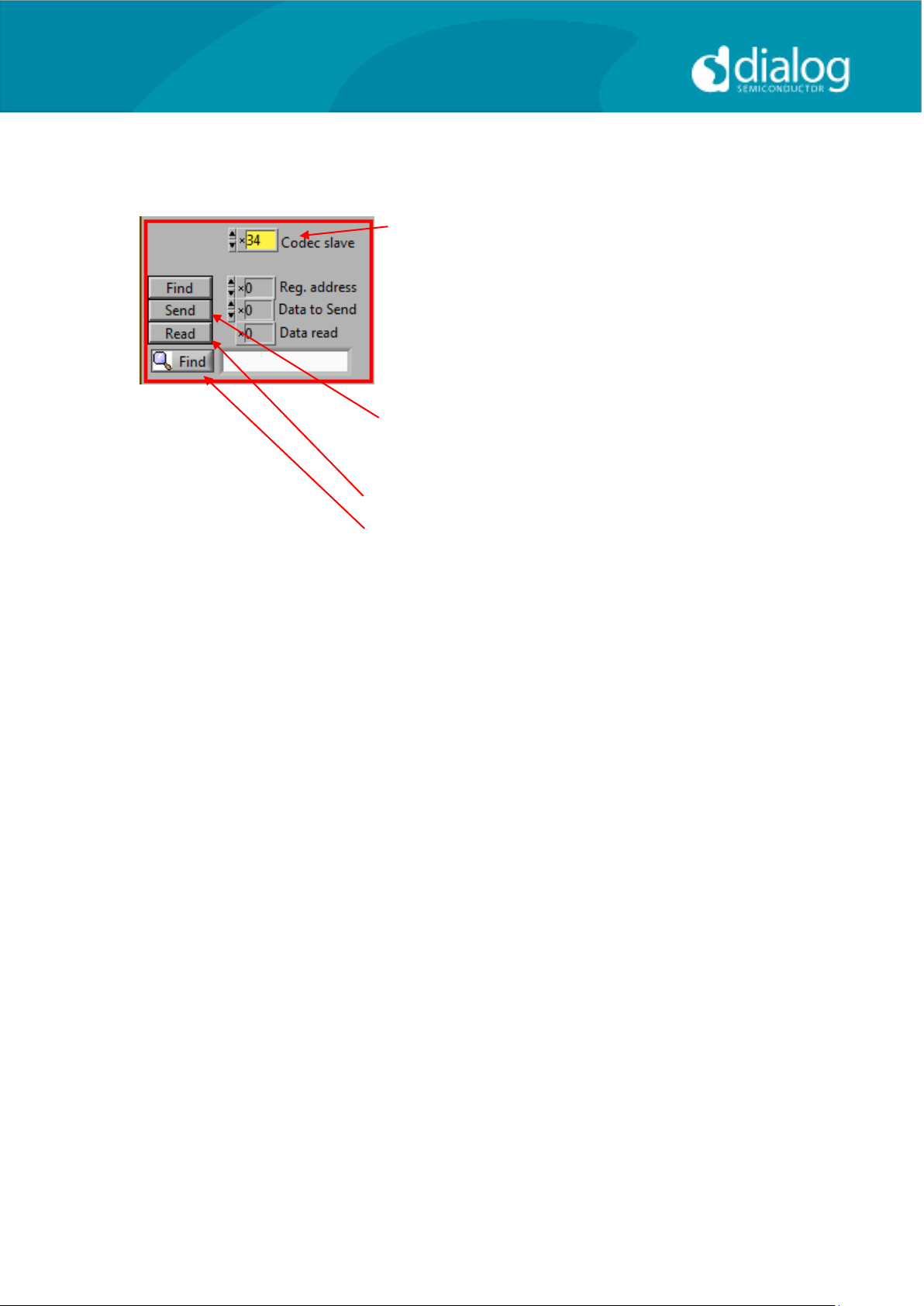
USB OK? Indicates that the USB is OK and
communicating.
Slave Address
Sets slave address of device. This affects all
I2C communications.
The codec slave addresses for DA7212 is 0x34.
Note that this is the 8bit value (34h for Write,
35h for Read).
Send Sends a single byte data to I2C device
using Slave Address, Register Address and
Data to Send.
Read Reads single byte data from I2C device
using Slave Address and Register Address.
Find Finds a control matching a full or partial
register name, a control bit name, a register
number (e.g. R23 or 17h). Pressing “Find”
repetitively will step through all matching
items.
Note: If Device Address does not match the port numbers on the device, this
can be used to control/read any other device on the I2C bus.
User Guide DA7212_Rev1v2 CONFIDENTIAL Page 15 of 34
Page 16
User Guide
DA7212 User Guide – Rev1.2
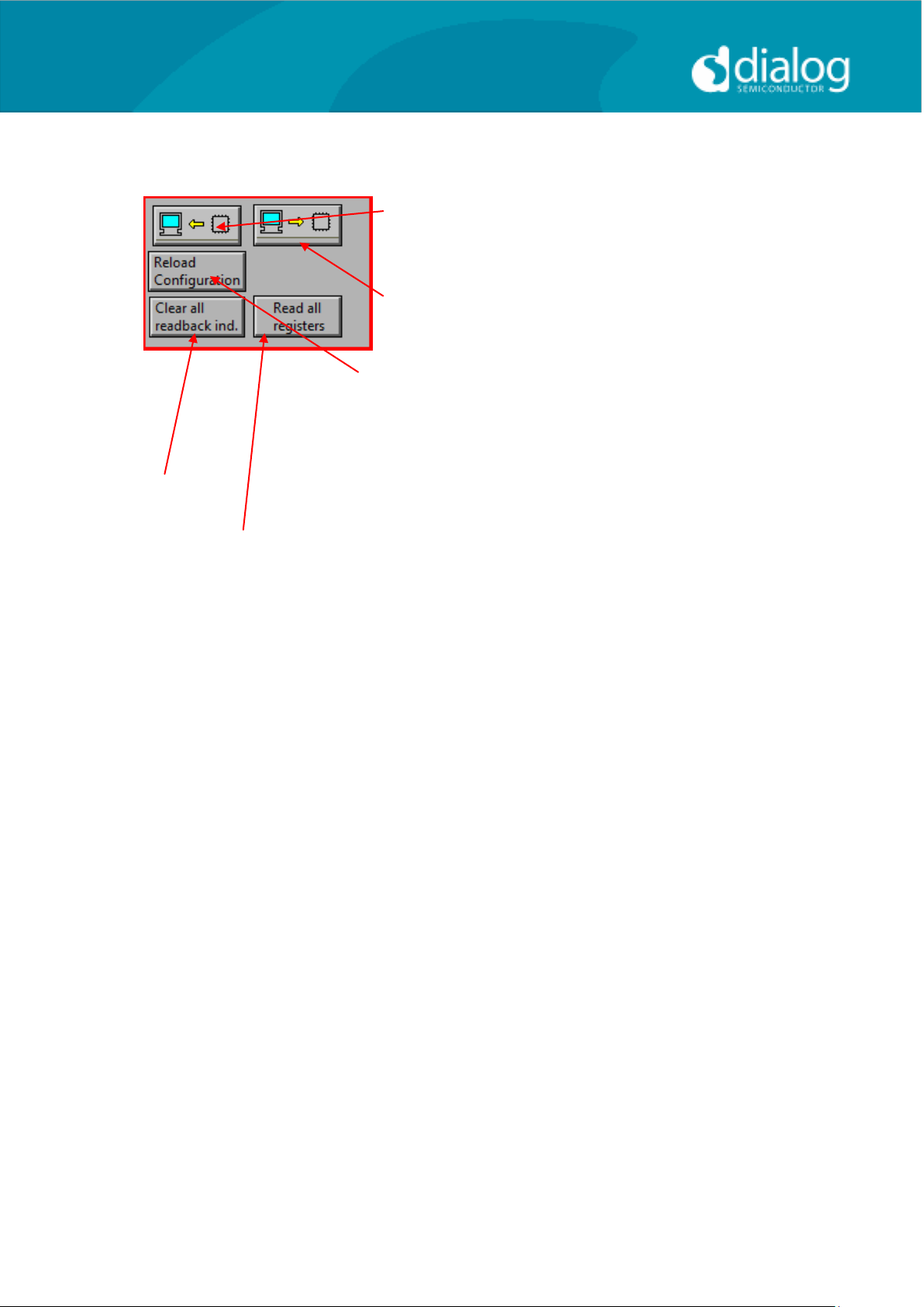
Synchronise Panel from Device
Reads all the register contents of the device
and updates the panel to match.
Synchronise Device from Panel
Writes all the device registers to match the
panel. (Refresh operation)
Reload Configuration
Resets registers to values specified in
configuration file for the PMIC section and default
values for the codec.
Clear all I2C readback indicators Sets all readback indicators to 0.
Read All Registers Reads all registers, comparing with
the panel controls.
User Guide DA7212_Rev1v2 CONFIDENTIAL Page 16 of 34
Page 17

User Guide
DA7212 User Guide – Rev1.2
Control Interface
The Codec Config, DAI and PLL, Analogue Inputs, Analogue Outputs, Mixers,
DAC Control, ADC Control, ALC control and Tone Gen pages all have the
same format.
Each register cluster comprises a control with a mixture of Boolean toggle
buttons, multi-value ring controls, or slide controls, as well as a hexadecimal
indicator showing the total equivalent register value and a readback indicator
showing the current register settings. The Event Register is labeled with a
Register number in decimal and its hexadecimal equivalent.
The Readback indicator readings can be switched individually to decimal,
octal, hexadecimal or binary by clicking on the “x”, or they may all be changed
at once between Hex and Binary by the “View>Binary Indicators” menu item.
User Guide DA7212_Rev1v2 CONFIDENTIAL Page 17 of 34
Page 18
User Guide
DA7212 User Guide – Rev1.2
Codec Config Page
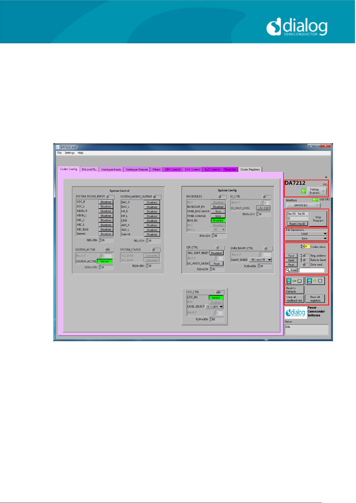
The Codec Config page allows access to the System Controller as well as
some basic system settings such as the references, IO levels and digital LDO.
To use the System Control panel (de)select the blocks as required for the
inputs and outputs and click the Submit button to apply the changes. If no
blocks are active then the System Active panel can be used to disable the onchip oscillator and put DA7212 into an ultra-low power standby state. The CIF
CTRL panel can be used to reset the chip and return all the registers to their
hardware defaults.
User Guide DA7212_Rev1v2 CONFIDENTIAL Page 18 of 34
Page 19
User Guide
DA7212 User Guide – Rev1.2
DAI and PLL Page
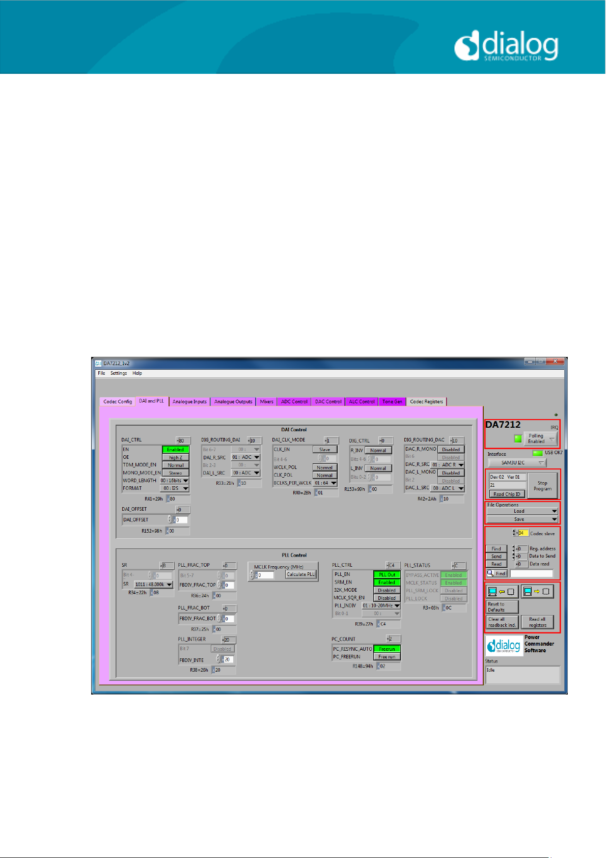
The DAI and PLL page allows control of the digital audio interface and phaselocked loop. The DAI CTRL panel sets the format on the DAI and the DAI CLK
MODE panel sets the master/slave mode as well as the clock polarity and
number of BCLKS per WCLK. The DIG ROUTING DAI panel selects the data
source for the DAI and DIG ROUTING DAC selects the data source for the
DAC.
The PLL Control panel contains all the settings for the PLL and on-chip
clocking. The SR panel sets the sample rate being used. The PLL CTRL
panel sets the input clock rate, whether the PLL is enabled and whether
sample rate matching (SRM) is required to track the DAI in slave mode. If the
PLL is required, the three FBDIV panels control the value of the feedback
divider. The required values can be calculated using the DA7212 PLL
Calculator spreadsheet, or they can be determined automatically by entering
the supplied MCLK frequency and pressing the Calculate PLL button. The
current status of the PLL is shown in the PLL STATUS panel. The PC COUNT
panel controls the behavior of the internal program counter.
User Guide DA7212_Rev1v2 CONFIDENTIAL Page 19 of 34
Page 20
User Guide
DA7212 User Guide – Rev1.2
Analogue Inputs
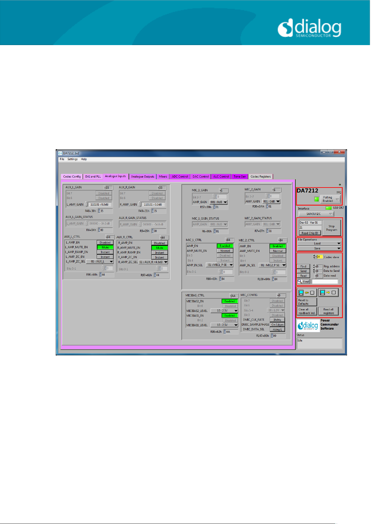
The Analogue Inputs page controls the input amplifiers and microphone
biases. Each of the GAIN panels sets the target gain for the amplifiers, and
the GAIN STATUS shows the currently active gain setting. Each of the CTRL
panels sets the enable, mute, and gain change behavior (ramped or zerocrossed) for the amplifiers. The MIC CTRL panels allow selection of singleended or differential input signal. The MICBIAS CTRL panel enables and sets
the output level for the microphone bias outputs. The MIC CONFIG panel sets
the clock and data format when digital microphones are used.
User Guide DA7212_Rev1v2 CONFIDENTIAL Page 20 of 34
Page 21
User Guide
DA7212 User Guide – Rev1.2
Analogue Outputs
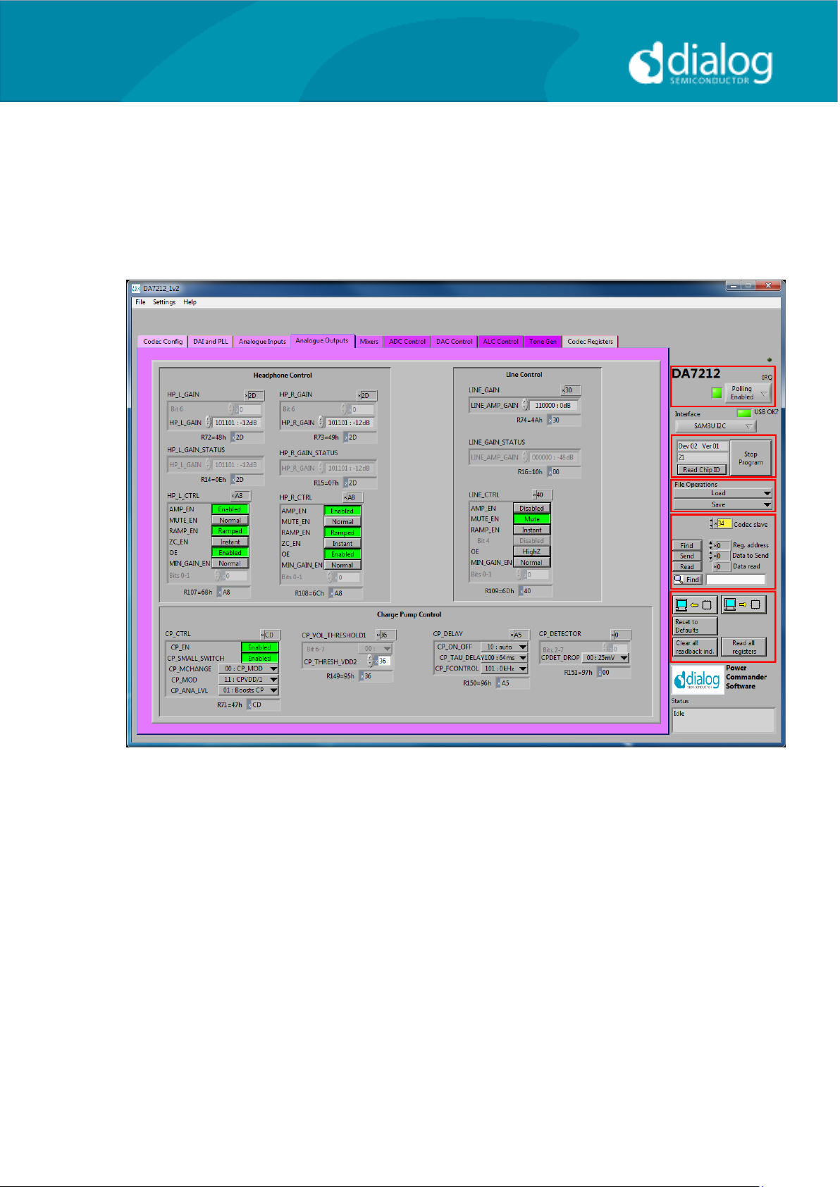
The Analogue Outputs page controls the headphone and line (speaker)
amplifiers as well as the charge pump for the headphone supplies. The GAIN,
GAIN STATUS and CTRL panels behave as for the Analogue Inputs page.
The Charge Pump Control controls the mode and switching behavior of the
charge pump as explained in the datasheet.
User Guide DA7212_Rev1v2 CONFIDENTIAL Page 21 of 34
Page 22
User Guide
DA7212 User Guide – Rev1.2
Mixers
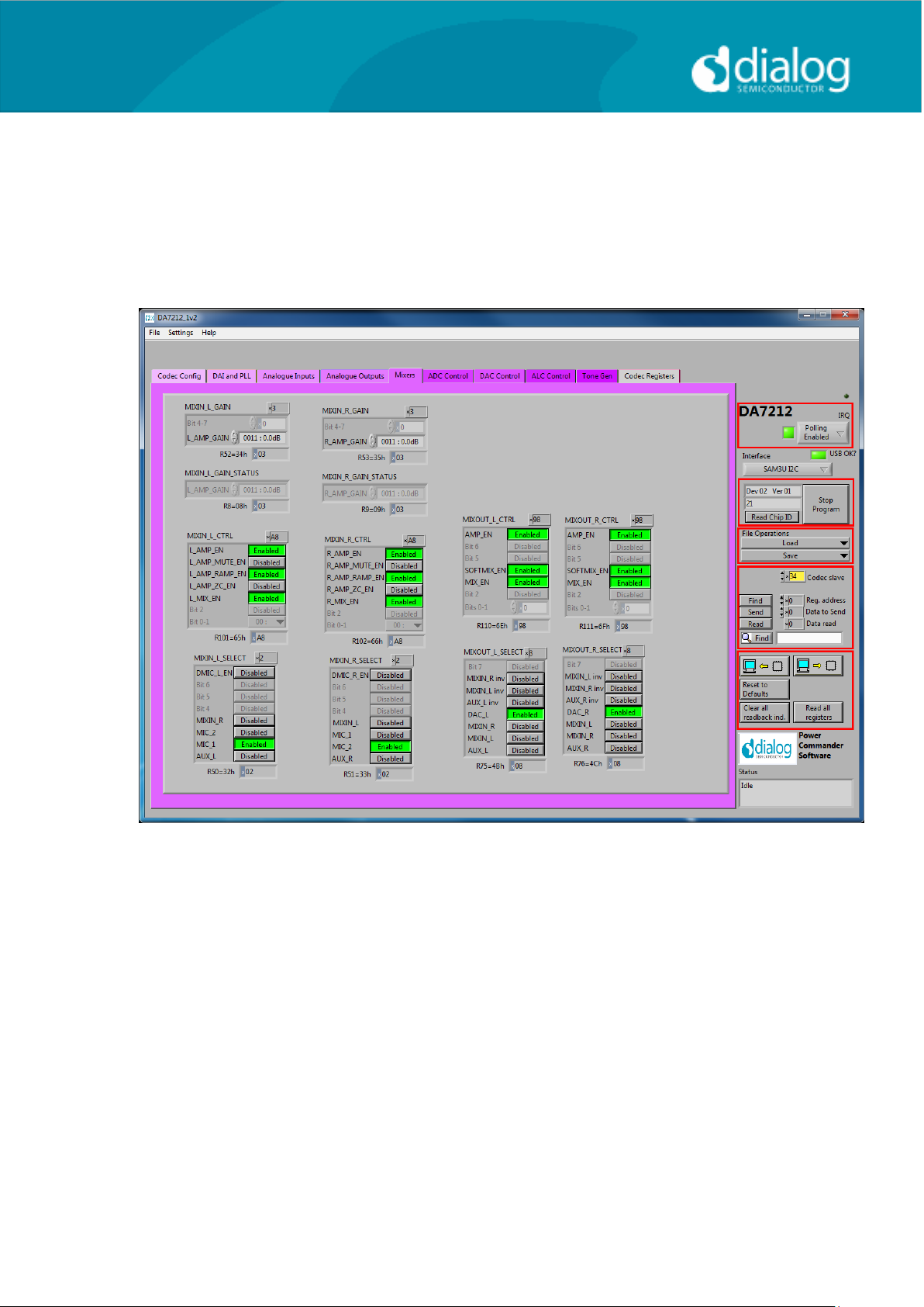
The Mixers page controls the behavior of the analogue input and output
mixers. The GAIN, GAIN STATUS and CTRL panels behave as for the
Analogue Inputs page. The MIXOUT CTRL panel also enables the Softmix
feature to ramp in/out the the select inputs. The SELECT panels controls
which inputs are routed to each of the four mixers.
User Guide DA7212_Rev1v2 CONFIDENTIAL Page 22 of 34
Page 23
User Guide
DA7212 User Guide – Rev1.2
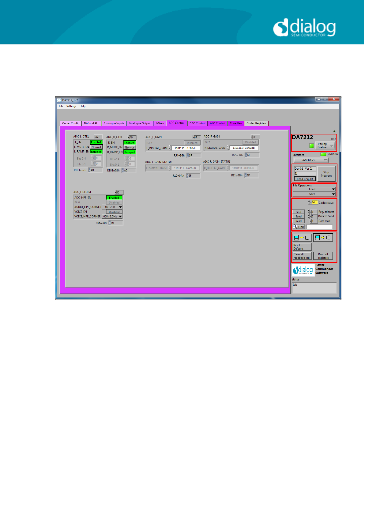
ADC Control
The ADC Control page enables the ADC, sets the digital gain applied after the
ADC and controls the behavior of the high-pass filter.
User Guide DA7212_Rev1v2 CONFIDENTIAL Page 23 of 34
Page 24
User Guide
DA7212 User Guide – Rev1.2
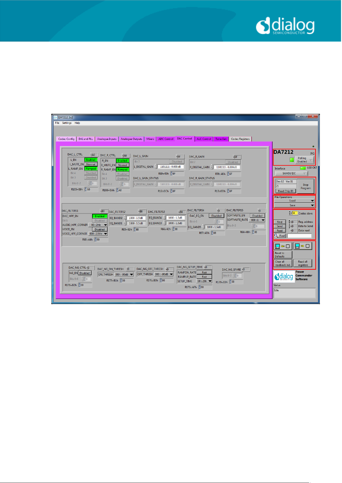
DAC Control
The DAC Control page controls the DAC, the DAC filters and the DAC noise
gate. The DAC FILTERS panels control the high-pass filter as well as the 5band EQ filter. There is also an option to apply a soft mute to the DAC input
signal. The DAC NG panels control the behavior of the DAC noise gate in
terms of its on and off thresholds, attack/decay rates and hold time.
User Guide DA7212_Rev1v2 CONFIDENTIAL Page 24 of 34
Page 25
User Guide
DA7212 User Guide – Rev1.2
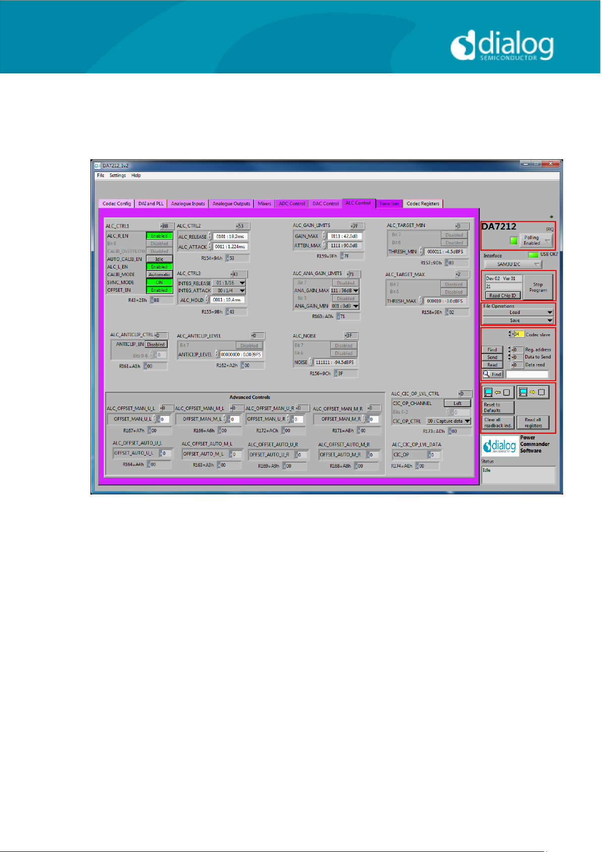
ALC Control
The ALC Control page configures the automatic level control on the record
path. The ALC behavior is described in detail in the datasheet.
User Guide DA7212_Rev1v2 CONFIDENTIAL Page 25 of 34
Page 26
User Guide
DA7212 User Guide – Rev1.2
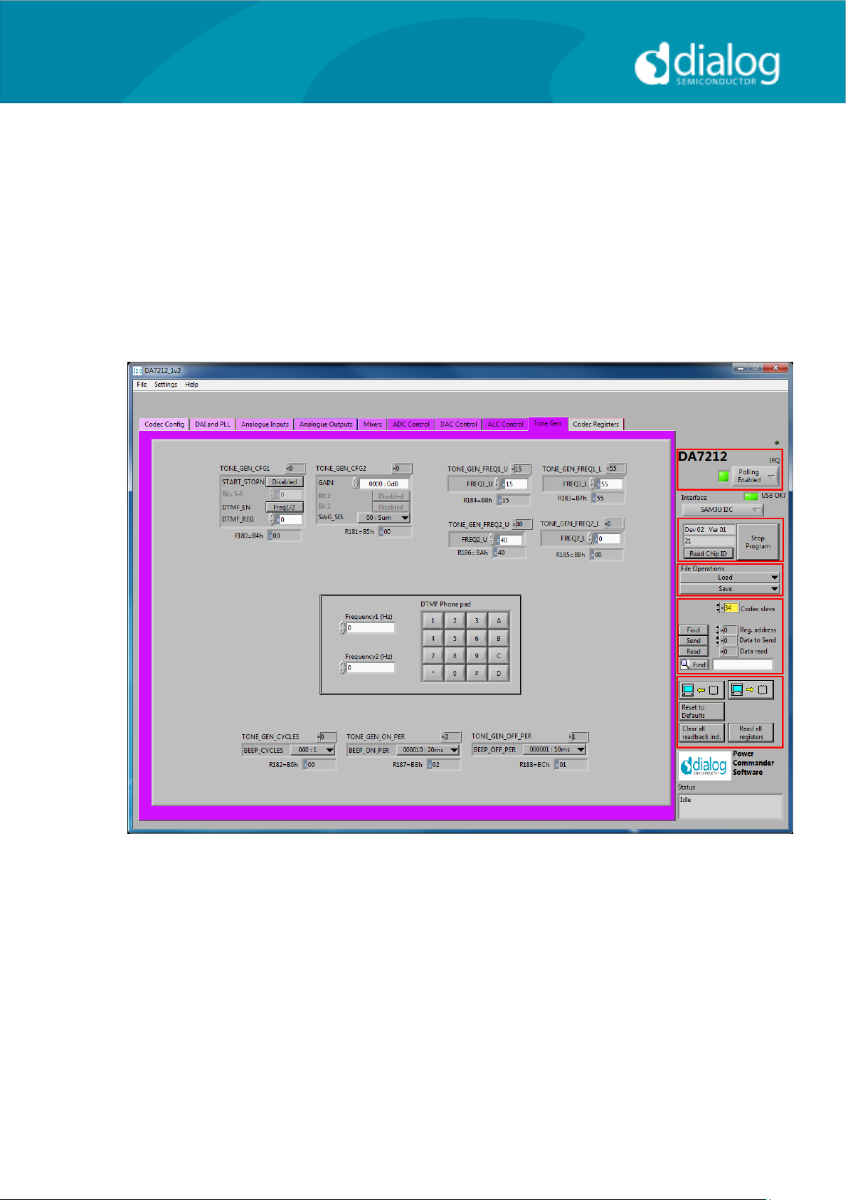
Tone Gen
The Tone Gen page controls the digital tone generator at the input to the
DAC. TONE GEN CFG1 panel starts the tone generator and enables a DTMF
tone if required. TONE GEN CFG2 panel sets the gain applied to the tone and
controls which sine-wave generator is used (or both). The TONE GEN FREQ
panels set the frequency for the two generators as described in the datasheet.
The DTMF Phone pad panel produces DTMF tones when the buttons are
pressed. The TONE GEN CYCLES panel controls how many beeps are
produced, and the TONE GEN ON and OFF PER panels control the on and
off periods.
User Guide DA7212_Rev1v2 CONFIDENTIAL Page 26 of 34
Page 27
User Guide
DA7212 User Guide – Rev1.2
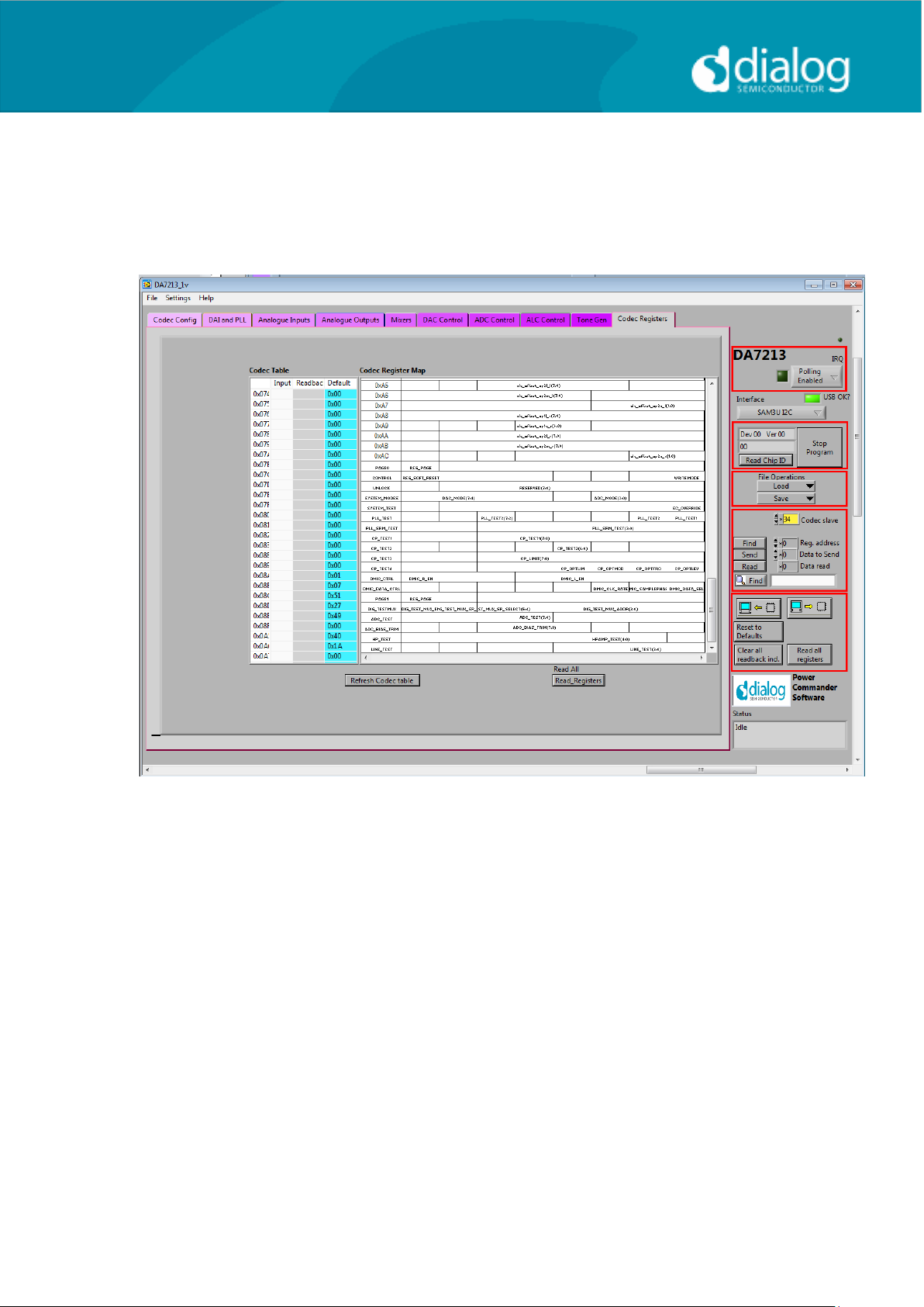
Codec Registers
This page presents the registers in a single table. The table is interactive, both
receiving changes made in other controls, and passing values to other
controls if changed in the table. In some conditions this register view may be
useful.
User Guide DA7212_Rev1v2 CONFIDENTIAL Page 27 of 34
Page 28

User Guide
DA7212 User Guide – Rev1.2
Troubleshooting
This section is an aid to resolving problems occurring in the previous sections.
Software Issues
The USB device should install without difficulty automatically. Make sure that
the installation finds and uses the driver contained in the USB memory stick.
If the program is started before the USB Interface board is plugged in, the
program will default to the offline mode. It can be useful to familiarise yourself
with the software in a desk environment without the hardware attached. If the
board is subsequently attached, move the Interface control to “USB”. Make
sure the USB is connected and then restart the program.
The software is optimized for a display screen size of 1024 by 768 pixels or
greater, with Fonts set to Normal (96dpi).
There have been reported issues of unpredictable display effects when large
fonts (120dpi) are used. This can be changed by right-clicking on the
desktop, select Properties. Select the Settings tab, select Advanced, then
Normal size from the drop-down box.
If communications are apparently lost, first press the “Start Device” button.
This attempts to make the device go active.
Also switching the “Interface mode” to Offline, then back to USB can
reinitialize the USB interface. Last resort is to unplug the USB then reconnect.
The software will detect this and reinitialize.
Hardware Issues
Most hardware problems can be traced to incorrect jumper positions.
Check carefully jumper positions by comparing them with the default positions
on page 7. Use the jumper table details and the board schematic as a guide to
the jumper functions and locations.
Selecting USB playback
The dialog DA7212 EVB coupled with the digital IO board allows a number of
audio sources to be selected with ease for testing and evaluation. One
example is to stream audio from a PC to the EVB over USB, This can easily
be done in the following way.
User Guide DA7212_Rev1v2 CONFIDENTIAL Page 28 of 34
Page 29
User Guide
DA7212 User Guide – Rev1.2
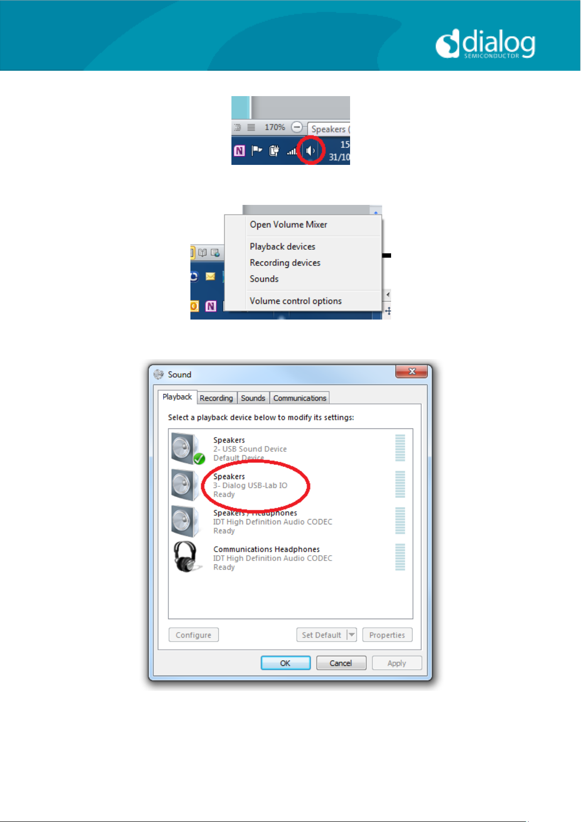
Right click on speaker symbol in task bar, circled in red
Select playback devices
Left click on Dialog US-Lab IO, then select “Set Default” and OK.
Audio played on the PC will now be streamed over USB to the digital IO board
for use on the DA7212 board.
User Guide DA7212_Rev1v2 CONFIDENTIAL Page 29 of 34
Page 30
User Guide
DA7212 User Guide – Rev1.2
Appendix A – Register Text File
The software includes the ability to save and load a text file containing
command codes representing the register addresses and data. This file is
principally used to save and load setup data, but may also be used to perform
a small degree of automation.
Note that at the end of the startup process, initiated by pressing “Start
Device”, a file “Host_configuration.txt” is loaded and run to emulate the host
processor writing immediately to the device.
If the option “Settings>Reg names in file” is set from the menu, register
names, rather than numbers, are used in the file, and the slave address is
replaced by the word “CODEC”. This is generally preferable and more
readable. Names are defined in the files “Registers_DA7212.h”, and
“Hardware_DA7212.h” that reside in the \Data\Drivers directory.
Hex codes for slave address and register address are still accepted on
reading in the file.
The use of the Save\logtest.txt facility permits register contents to be
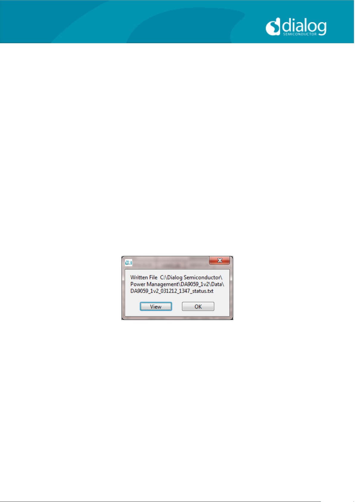
transferred to the user‟s own software. Clinking on Save\logtest.txt brings up
the following panel, showing the location and name of the saved file. This is a
Register dump of the entire device.
Example message box.
I2C Register Text File Format
The following formats are used for both read and write in the text file.
Numbers apart from time delays are always expressed in Hex,
separated by tabs. The use of “0x” in front of the hex value is optional.
The first parameter is the device slave address in 8bit format. OR
The first parameter is a token:
o “WRITE2” or “CODEC” will write to the CODEC device at the
currently selected slave address (I2C mode only).
o “READ2” will read from the CODEC device at the values of a
number of registers.
User Guide DA7212_Rev1v2 CONFIDENTIAL Page 30 of 34
Page 31

User Guide
DA7212 User Guide – Rev1.2
o “DELAY” or “WAIT” will implement a time delay specified up to
65535 milliseconds. The delay time is specified in decimal or
hex if preceded by “0x”.
o ITERATE will cause the whole script to be repeated the
specified number of times.
The second parameter is the register address as a name or hex value.
The third parameter is the data.
Comments (i.e. lines beginning with „//‟) are permitted in the file.
Inline comments (i.e. //comment) are permitted.
The data will be processed in the order written and written directly to
the specified device. The screen controls will be updated once
command in the file have finished.
The use of the slave address in the file allows any device attached to
the I2C bus to be controlled.
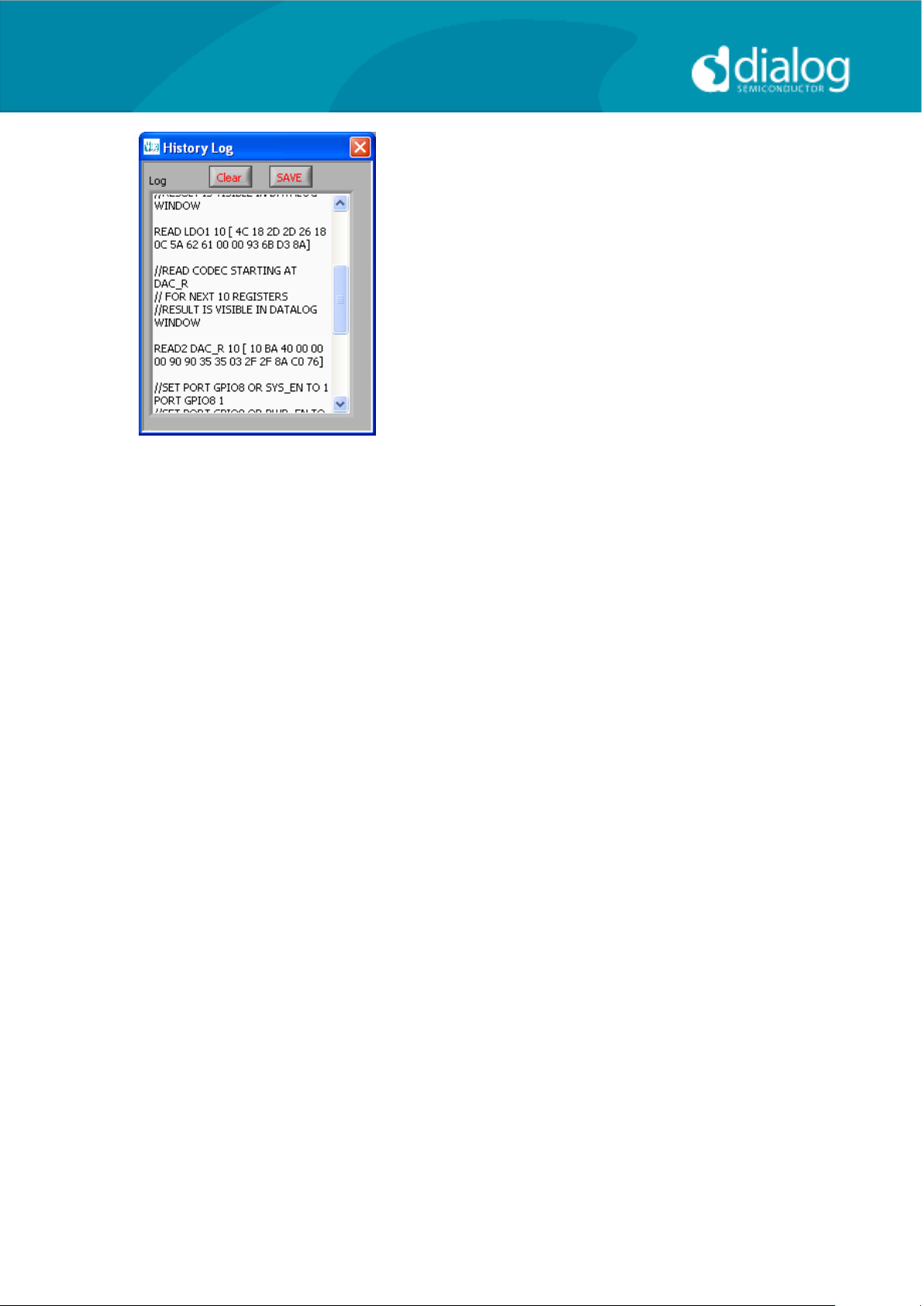
For read operations, the result of the read is passed to the history log
window.
Example files contents:
//Write to CODEC in 3 ways
CODEC MIC_L 0x01
WRITE2 MIC_R 0x02
0x34 0x09 0xB1
//Read CODEC starting at DAC_R
// for next 10 registers
//Result is visible in Datalog window
READ2 DAC_R 10
//Wait 255ms
DELAY 255
WAIT 0xFF
Alternative form
//Register Dump
//Slave Register Data
0x92 0x01 0x00
0x92 0x02 0x01
0x92 0x03 0x02
0x92 0x04 0x02
0x92 0x05 0x04
0x92 0x06 0x05
0x92 0x07 0x06
0x92 0x08 0x07
0x92 0x09 0x08
The results in the history log file are shown below.
The Read operations are in brackets following the command.
User Guide DA7212_Rev1v2 CONFIDENTIAL Page 31 of 34
Page 32
User Guide
DA7212 User Guide – Rev1.2
User Guide DA7212_Rev1v2 CONFIDENTIAL Page 32 of 34
Page 33
User Guide
DA7212 User Guide – Rev1.2
Appendix A – Socketed Miniboard (169-01-A)
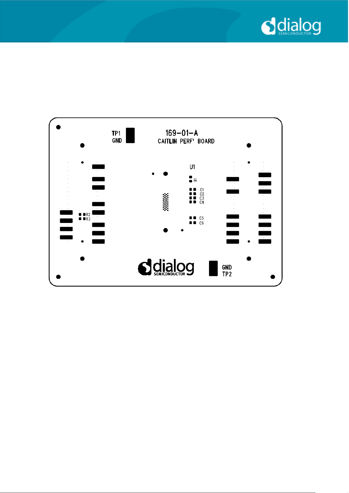
A socketed miniboard is available for evaluation purposes. This PCB uses
larger passive components (0402) to allow for customer experimentation. A
soldered device can replace the socket on request.
Figure 5 DA7212 Mini Board
User Guide DA7212_Rev1v2 CONFIDENTIAL Page 33 of 34
Page 34
User Guide
DA7212 User Guide – Rev1.2
REVISION
DATE
ORIGINATOR CHANGE
1.0
28/06/2013
CM
Initial Release
1.1
20/11/2013
CM
Updated default jumper locations
1.2
21/11/2013
PH
Added description for each page in the GUI
This publication is issued to provide outline information only, which (unless agreed by Dialog Semiconductor in writing) may not be used, applied or
reproduced for any purpose or form part of any order or contract or be regarded as a representation relating to products or services concerned. Dialog
Semiconductor reserves the right to alter without notice the specification, design, price or conditions of supply of the product. Customer takes note that
Dialog Semiconductor’s products are not designed for use in devices or systems intended for supporting or monitoring life nor for surgical implants into
the body. Customer shall notify the company of any such intended use so that Dialog Semiconductor may determine suitability. Customer agrees to
indemnify Dialog Semiconductor for all damages that may be incurred due to use without the company’s prior written permission of products in such
Email: [email protected]
www.dialog-semiconductor.com
Dialog Semiconductor Worldwide
Germany (Headquarter)
Tel: (+49) 7021 805-0
Fax (+49) 7021 805-100
USA
Tel: (+1) 949 623 8686
Fax: (+1) 949 623 8305
United Kingdom
Tel: (+44) 1793 757700
Fax: (+44) 1793 757800
Japan
Tel: +81-3-3215-5123
Fax +81-3-3125-5124
Taiwan
Tel: +886 22 67 57 876
Fax +886 22 67 54 098
China
Tel: (+852) 2607 4271
Fax: (+852) 2607 4169
REVISION HISTORY
User Guide DA7212_Rev1v2 CONFIDENTIAL Page 34 of 34
Page 35

Mouser Electronics
Authorized Distributor
Click to View Pricing, Inventory, Delivery & Lifecycle Information:
Dialog Semiconductor:
DA7212-EVAL
 Loading...