

Page 1

December 2011
64-0347-09
www.dialogic.com
Dialogic® 4000 Media Gateway Series SU4.1
Reference Guide
Page 2

This page intentionally left blank
Page 3

Copyright and Legal Notice
Copyright © 2007-2011 Dialogic Inc. All Rights Reserved. You may not reproduce this document in whole or in part
without permission in writing from Dialogic Inc. at the address provided below.
All contents of this document are furnished for informational use only and are subject to change without notice and
do not represent a commitment on the part of Dialogic Inc. and its affiliates or subsidiaries (―Dialogic‖). Reasonable
effort is made to ensure the accuracy of the information contained in the document. However, Dialogic does not
warrant the accuracy of this information and cannot accept responsib ility for errors, inaccuracies or omissions that
may be contained in this document.
INFORMATION IN THIS DOCUMENT IS PROVIDED IN CONNECTION WITH DIALOGIC® PRODUCTS. NO LICENSE,
EXPRESS OR IMPLIED, BY ES TOPPEL OR OTHERWISE, TO ANY INTELLECTUAL PROPERTY RIGHTS IS GRANTED BY
THIS DOCUMENT. EXCEPT AS PROVIDED IN A SIGNED AGREEMENT BETWEEN YOU AND DIALOGIC, DIALOGIC
ASSUMES NO LIABILITY WHATSOEVER, AND DIALOGIC DISCLAIMS ANY EXPRESS OR IMPLIED WARRANTY,
RELATING TO SALE AND/OR USE OF DIALOGIC PRODUCTS INCLUDING LIABILITY OR WARRANTIES RELATING TO
FITNESS FOR A PARTICULAR PURPOSE, MERCHANTABILITY, OR INFRINGEMENT OF ANY INTELLECTUAL PROPERTY
RIGHT OF A THIRD PARTY.
Dialogic products are not intended for use in certain safety-affecting situations. Please see
http://www.dialogic.com/company/terms-of-use.aspx for more details.
Due to differing national regulations and approval requirements, certain Dialogic products may be suitable for use
only in specific countries, and thus may not function properly in other countries. You are responsible for ensuring
that your use of such products occurs only in the countries where such use is suitable. For information on specific
products, contact Dialogic Inc. at the address indicated below or on the web at www.dialogic.com.
It is possible that the use or implementation of any one of the concepts, applications, or ideas described in this
document, in marketing collateral produced by or on web pages maintained by Dialogic may infringe one or more
patents or other intellectual property rights owned by third parties. Dialogic does not provide any intellectual
property licenses with the sale of Dialogic products other than a license to use such product in accordance with
intellectual property owned or validly licensed by Dialogic and no such licenses are provided except pursuant to a
signed agreement with Dialogic. More detailed information about such intellectual property is available from
Dialogic‘s legal department at 1504 McCarthy Boulevard, Milpitas, CA 95035-7405 USA. Dialogic encourages all
users of its products to procure all necessary intellectual property licenses required to implement any
concepts or applications and does not condone or encourage any intellectual property infringement and
disclaims any responsibility related thereto. These intellectual property licenses may differ from
country to country and it is the responsibility of those who develop the concepts or applications to be
aware of and comply with different national license requirements.
Dialogic, Dialogic Pro, Dialogic Blue, Veraz, Brooktrout, Diva, Diva ISDN, Making Innovation Thrive, Video is the
New Voice, VisionVideo, Diastar, Cantata, TruFax, SwitchKit, SnowShore, Eicon, Eiconcard, NMS Communications,
NMS (stylized), SIPcontrol, Exnet, EXS, Vision, PowerMedia, PacketMedia, BorderNet, inCloud9, I-Gate,
ControlSwitch, NaturalAccess, NaturalCallControl, NaturalConference, NaturalFax and Shiva, among others as well
as related logos, are either registered trademarks or trademarks of Dialogic Inc. and its affiliates or subsidiaries.
Dialogic‘s trademarks may be used publicly only with permission from Dialogic. Such permission may only be
granted by Dialogic‘s legal department at 1504 McCarthy Boulevard, Milpitas, CA 95035-7405 USA. Any authorized
use of Dialogic‘s trademarks will be subject to full respect of the trademark guidelines published by Dialogic from
time to time and any use of Dialogic‘s trademarks requires proper acknowledgement.
Internet Explorer, Microsoft, Windows, Windows Server, Lync, and Windows Vista are registered trademarks or
trademarks of Microsoft Corporation in the United States and/or other countries. Other names of actual companies
and products mentioned herein are the trademarks of their respective owners.
This document discusses one or more open source products, systems and/or releases. Dialogic is not responsible
for your decision to use open source in connection with Dialogic products (including without limitation those
referred to herein), nor is Dialogic responsible for any present or future effects such usage might have, including
without limitation effects on your products, your business, or your intellectual property rights
Page 4

This page intentionally left blank
Page 5

Table of Contents
1. Introduction .................................................................................................. 1
About This Manual ................................................................................................... 1
2. Dialogic® 4000 Media Gateway Features ...................................................... 3
Dialogic® Diva® SIPcontrol Features ......................................................................... 3
General Features .................................................................................................. 3
Call Handling Features........................................................................................... 4
Media Processing Features ..................................................................................... 5
Supported RFCs .................................................................................................... 5
Enhanced Routing ................................................................................................. 6
Enhanced Address Manipulation .............................................................................. 6
Dialogic® Diva® Media Board Features ...................................................................... 7
General Features .................................................................................................. 7
DSP-Based Features.............................................................................................. 8
Fax and Modem Features ....................................................................................... 8
Q.SIG Features .................................................................................................... 9
Channelized T1 (Robbed Bit Signaling) .................................................................... 9
PBX Interoperability ............................................................................................... 10
3. Initial Configuration and License Activation ................................................ 11
Preparing for Configuration ..................................................................................... 11
License Activation .................................................................................................. 11
Device Unique ID (DUID) ....................................................................................... 12
Proof of Purchase Code (PPC).................................................................................. 12
To Register Your PPC and DUID ............................................................................... 12
To Activate a License File ....................................................................................... 14
4. Dialogic® Diva® Media Board Configuration ............................................... 15
Dialogic® Diva® Media Board Configuration ............................................................. 15
Dialogic® Diva® Media Board Configuration via the Dialogic® Diva® Web Interface ..... 15
The Board Monitor .............................................................................................. 17
The View Report Option ....................................................................................... 18
Supported Switch Types and Supported PBXs ........................................................... 22
Public Line ISDN Protocols ................................................................................... 22
Carrier Grade ..................................................................................................... 23
POTS ................................................................................................................ 23
PBX Protocols ..................................................................................................... 23
Specific Major PBX Types ..................................................................................... 23
5. Dialogic® Diva® SIPcontrol™ Configuration ............................................... 25
Dialogic® Diva® SIPcontrol™ Configuration ............................................................. 25
About Dialogic® Diva® SIPcontrol™ Configuration .................................................... 25
Opening the Dialogic® Diva® SIPcontrol™ Web Interface ....................................... 25
Dialogic® Diva® SIPcontrol™ Configuration Sections .............................................. 26
Configuration Tips and Hints ................................................................................ 26
Configuring Dialogic® Diva® SIPcontrol™ ................................................................ 27
Using the Configuration Wizard ............................................................................ 27
Loading an Existing Configuration Profile ............................................................... 28
Importing an Existing Configuration File ................................................................ 28
Configuring Diva SIPcontrol Manually .................................................................... 29
Saving Configuration Settings ................................................................................. 30
Saving Configuration Settings as a Configuration Profile .......................................... 30
v
Page 6

Dialogic 4000 Media Gateway Series SU4.1 Reference Guide
Exporting Configuration Settings .......................................................................... 30
Deleting a Configuration Profile ............................................................................... 30
PSTN Interfaces .................................................................................................... 31
General ............................................................................................................. 31
Enhanced .......................................................................................................... 32
Address Normalization ......................................................................................... 34
Message Waiting Indication (MWI): ....................................................................... 36
Network Interfaces ................................................................................................ 37
SIP Peers ............................................................................................................. 38
General ............................................................................................................. 38
Enhanced .......................................................................................................... 40
Security ............................................................................................................ 43
Session Timer .................................................................................................... 44
Address Normalization ......................................................................................... 45
Authentication .................................................................................................... 46
Routing ................................................................................................................ 47
General ............................................................................................................. 47
Address Normalization For Condition Processing (Using Source Dialplan) ................... 48
Conditions ......................................................................................................... 49
Address Manipulation .......................................................................................... 52
Security Profiles .................................................................................................... 53
Global Security Parameters .................................................................................. 54
LDAP ................................................................................................................... 56
How to Use LDAP to Access Active Directory for Routing Calls via Diva SIPcontrol ....... 56
Use Case for LDAP .............................................................................................. 56
LDAP Query ....................................................................................................... 57
LDAP Domain ..................................................................................................... 58
LDAP Cache ....................................................................................................... 60
Dialplans .............................................................................................................. 61
Important information about the outside access digit configuration ........................... 61
Address Maps ....................................................................................................... 64
Cause Code Maps .................................................................................................. 68
Codec Profiles ....................................................................................................... 70
Registrations......................................................................................................... 72
Logging and Diagnostics ......................................................................................... 74
6. Data Security .............................................................................................. 75
Data Security Overview .......................................................................................... 75
Secure HTTP ......................................................................................................... 75
TLS ...................................................................................................................... 75
Secure RTP ........................................................................................................... 76
Using Certificates for Authentication and Data Encryption ........................................... 76
Generating Private Key Files and Certificates ............................................................ 77
Uploading the Certificate Authority, Certificate, and Key Files to Dialogic® Diva®
SIPcontrol™ .......................................................................................................... 83
7. How Calls are Processed ............................................................................. 85
How Calls are Processed ......................................................................................... 85
Information about Call Processing............................................................................ 88
Emergency Calls .................................................................................................... 88
Routing Conditions ................................................................................................ 88
Routing Examples .................................................................................................. 88
Direct Routing between One PSTN Interface and One SIP Peer ................................. 89
Direct Routing between Two SIP Peers .................................................................. 89
vi
Page 7

Table of Contents
Connecting Two SIP Peers to Two PSTN Interfaces Exclusively ................................. 90
Connecting Two SIP Peers to the Same PSTN Interface ........................................... 90
Load Balancing or Failover between Two SIP Peers ................................................. 91
8. How Call Addresses are Processed .............................................................. 93
Overview of How Call Addresses are Processed ......................................................... 93
Number Normalization Based on a Dialplan ............................................................... 93
Steps for Number Normalization Based on a Dialplan .............................................. 94
Number Modification Using Address Maps ................................................................. 94
Common Expressions: ......................................................................................... 95
Common Results ................................................................................................ 95
Address Map Examples ........................................................................................ 96
How Call Addresses are Manipulated ........................................................................ 98
Possible Call Routing Scenarios ............................................................................... 98
9. Software Uninstallation .............................................................................. 99
Software Uninstallation .......................................................................................... 99
To uninstall Diva SIPcontrol under Windows® XP or Windows Server® 2003: ............ 99
To uninstall Diva SIPcontrol under Windows Vista®, Windows Server® 2008, or
Windows® 7: ..................................................................................................... 99
10. Cause Code Mapping ................................................................................. 101
Cause Code Mapping ............................................................................................ 101
Default Cause Code Mapping................................................................................. 101
ISDN Cause Code to SIP Response Code ............................................................. 101
SIP Response Code to ISDN Cause Code ............................................................. 104
Default Cause Code Mapping for Microsoft® Office Communications Server 2007 and
Lync Server 2010 Peers ..................................................................................... 106
Microsoft® Office Communications Server 2007 and Lync Server 2010 ISDN Cause Code
to SIP Response Code ....................................................................................... 106
Microsoft® Office Communications Server 2007 and Lync Server SIP Response Code to
ISDN Cause Code ............................................................................................. 109
11. Event Logging ........................................................................................... 113
Event Logging ..................................................................................................... 113
Errors ............................................................................................................. 113
Warnings ......................................................................................................... 114
Informational Messages ..................................................................................... 115
12. Use Case Examples ................................................................................... 117
Use Case Examples .............................................................................................. 117
Use Case for Dialogic® HMP Software .................................................................... 117
Use Case for Microsoft® Exchange Server 2007 ...................................................... 120
Using the Gateway Computer between the PBX and Microsoft® Office Communications
Server 2007 ....................................................................................................... 124
Using the Gateway Computer Between the PBX/PSTN and Microsoft® Office
Communications Server 2007 ............................................................................... 130
Creating the Routes for This Scenario .................................................................. 142
Using the Gateway Computer Between the PSTN and PBX/Microsoft® Office
Communications Server 2007 ............................................................................... 146
Creating Address Maps for This Scenario ............................................................. 155
Creating Routes for This Scenario ....................................................................... 163
Using the Gateway Computer Between the PSTN and Microsoft® Lync™ Server 2010 .. 167
Creating the SIP Peers for This Scenario .............................................................. 178
Creating Routes for This Scenario ....................................................................... 182
vii
Page 8

Dialogic 4000 Media Gateway Series SU4.1 Reference Guide
13. SNMP Support ........................................................................................... 191
Activating SNMP Support For a Dialogic® Diva® Media Board ................................... 191
Installing the Windows SNMP Service ..................................................................... 191
Adding the SNMP Service in the Dialogic® Diva® Configuration Manager ................... 195
Verifying the SNMP Service Status ......................................................................... 195
Verifying the Function of the SNMP Service ............................................................. 197
Supported MIBs, OIDs, and Traps .......................................................................... 198
14. Verifying the Line Configuration with the Dialogic® Diva® Line Test Tool 203
How to Verify the Line Configuration with the Dialogic® Diva® Line Test Tool ............ 203
Performing a Line Check Test ................................................................................ 203
Performing a Hardware Test ................................................................................. 205
Performing a Phone/Loop Test .............................................................................. 205
Advanced setup ................................................................................................ 206
Performing a Call Transfer Test ............................................................................. 207
Advanced transfer setup .................................................................................... 207
Performing a Fax Test .......................................................................................... 208
Setting Up a Test for Incoming Fax Calls ............................................................. 208
Writing a Message into a Trace File ..................................................................... 209
15. Creating a Trace with the Dialogic® Diva® Diagnostics Tool ..................... 211
How to Create a Trace with the Dialogic® Diva® Diagnostics Tool ............................. 211
16. Backing Up and Restoring the Configuration ............................................. 215
How to Back Up and Restore the Configuration ........................................................ 215
17. Customer Service ...................................................................................... 217
Customer Service ................................................................................................ 217
Dialogic® Diva® Support Tools .......................................................................... 217
Dialogic Services and Support Web Site ............................................................... 217
Dialogic Customer Support ................................................................................ 218
viii
Page 9

1. Introduction
About This Manual
The Dialogic® 4000 Media Gateway Series are pre-installed with the Windows versions of the
Dialogic® Diva® System Release Software and Dialogic® Diva® SIPcontrol™. This reference
guide contains relevant information about both software versions, such as Diva SIPcontrol
configuration parameters, the Dialogic® Diva® Diagnostics tool, the Dialogic® Diva® Line Test
tool, and the SNMP configuration for Dialogic® Diva® Media Boards. Various configuration
scenarios are also included, as well as information about the different support options.
The term "DMG4000 Gateways" is used herein to refer collectively to the Dialogic® 4000
Media Gateway Series and the term "DMG4000 Gateway" is used herein to refer a gateway
in the Dialogic® 4000 Media Gateway Series.
For a list of Diva SIPcontrol features, see Dialogic® Diva® SIPcontrol Features.
For a list of Diva Media Board features, see Dialogic® Diva® Media Board Features.
1
Page 10

This page intentionally left blank
Page 11

2. Dialogic® 4000 Media Gateway Features
Dialogic® Diva® SIPcontrol Features
This topic groups Diva SIPcontrol features into the following categories:
General features
Call handling features
Media processing features
Supported RFCs
Enhanced routing
Enhanced address manipulation
General Features
Support for Microsoft
Noise suppression support
Echo cancellation selectable via GUI
®
Lync™ Server 2010
Forward the display name from SIP to Q.SIG and vice versa
Interoperability with Dialogic
®
Host Media Processing (HMP) software 3.0WIN and
3.1LIN
Configuration via the Diva SIPcontrol web interface
Standard web browsers can be used for configuring. Diva SIPcontrol has been tested
with the following browsers:
Microsoft
®
Internet Explorer® Version 7 and 8
Mozilla Firefox version 3.6.x
Remote configuration of Diva SIPcontrol from any computer in the network. The
configuration may be encrypted.
Cause codes: Configurable translation of ISDN cause code to SIP response code and
vice versa; consequently, Diva SIPcontrol can adapt to the specific behavior of the
PSTN, PBX, and/or SIP peer.
Configuration changes during runtime: Modify most parameters of Diva SIPcontrol
without the need to restart the service; active calls are not affected by configuration
updates and continue undisturbed.
Support for the North American numbering plan: The configuration of multiple area
codes is handled as local. Therefore, the Diva SIPcontrol dialplan engine is able to
automatically format dialed numbers according to local phone provider requirements
without any additional regular expressions.
Interoperability with the Dialogic
®
Brooktrout® Bfv API SDK: The Dialogic®
Brooktrout® SR140 Fax Software version 5.2.1 has been confirmed via testing to be
V.34/T.38 interoperable with Diva SIPcontrol. The Brooktrout SR140 Fax Software is
high-performance, host-based T.38 fax software for IP networks.
Codec configuration: Configuration options for supported audio and fax codecs. See
Media Processing Features for supported codecs.
3
Page 12

Dialogic 4000 Media Gateway Series SU4.1 Reference Guide
Support for Proxy and Registrar authentication.
Support for registering Diva SIPcontrol as an e-phone gateway.
Support for early media. Early media is supported to and from the PSTN due to Any-
to-Any routing, if the line protocol supports it. A call using early media does not need
to have a SIP leg.
Configuration of Diva Media Board parameters via the Diva web interface
Support for up to 64 ports per system for Dialogic
®
Diva® BRI and Analog Media
Board installations
Support for up to 240 ports per system for Dialogic
®
Diva® PRI Media Board
installations
Call Handling Features
SIP methods: ACK, BYE, INVITE, NOTIFY, REFER, CANCEL, OPTIONS, PRACK
Configurable IP transport layer TCP, UDP, or TLS
Support for TLS encryption and authentication
Support for SRTP (secure Real-time Transport Protocol)
Support for SIPS (Secure SIP)
Basic call incl. numbering services:
o Called Party Number
o Calling Party Number
o Redirecting Number
Call Routing
Call Hold/Retrieve (e.g., Re-Invite mapping towards ISDN)
SIP-side Call Transfer as transfer target (C-party) and as transferee (A-party)
PSTN-side incoming Call Diversion
Message Waiting Activation / Deactivation*
Support for SIP 302 REDIRECT, which works as follows: a SIP call is redirected per
302 Redirect with new IP port numbers (as used with Microsoft® Office
Communications Server 2007, Microsoft® Office Communications Server 2007 R2,
and Microsoft® Exchange Server 2007 without changing the IP address)
Support for SIP Refer: a SIP call is redirected per SIP Refer to a new SIP target,
using Replaces and Referred By
SIP Session Timer (RFC 4028)
Simplified Number Normalization based on PSTN connection parameters
Number Manipulation using Regular Expressions
* NOTIFY in combination with SUBSCRIBE is used to provide the feature Message Waiting
Activation / Deactivation with regular SIP clients. However, in a gateway configuration,
applications are using the features without the need for Diva SIPcontrol to use SUBSCRIBE.
4
Page 13

Dialogic® 4000 Media Gateway Features
Media Processing Features
Support for the following codecs:
o G.711 A-law and u-law
o G.726 (16, 24, 32, and 40 kbps)
o G.729*
o GSM-FR
o iLBC**
o sRTP
RTP dynamic payload audio/telephony event
RTP profile RTP/AVP
DTMF via RTP payload/telephony event (RFC 2833 or RFC 4733)
PSTN-side fax tone detection via RTP event (RFC 2833 or RFC 4733)
128 ms Echo Canceller supported on all boards, and additionally, 256 ms EC
supported on those boards listed in MultiPRI boards section.
Reliability:
o Load balancing and failover on PSTN side
o Load balancing and failover on SIP side (optionally uses OPTIONS for keep-
alive check)
o Alive check for active calls on SIP side via SIP session timer
*For G.729, you need to purchase and activate a license before you can use it. For more
information, see the Dialogic® 4000 Media Gateway Series Quickstart Guide, which is
available at http://www.dialogic.com/manuals/dmg30004000. G.729 is only available on
Dialogic® Diva® Multiport V-PRI Media Boards.
**iLBC is only available on Diva Multiport V-PRI Media Boards. On Dialogic® Diva® V-
4PRI/E1/T1-120 PCIe HS boards and Dialogic® Diva® V-8PRI/E1/T1-240 PCIe FS boards, up to 18
channels for each PRI port are supported.
Supported RFCs
RFC 2617 - HTTP Digest Authentication
RFC 2833 - RTP Payload for DTMF Digits, Telephony Tones and Telephony Signals
RFC 3261 - Session Initiation Protocol
RFC 3262 - Reliability of Provisional Responses in Session Initiation Protocol (SIP)
RFC 3264 - An Offer/Answer Model with Session Description Protocol
RFC 3265 - SIP-specific Event Notification
RFC 3326 - The Reason Header Field for the Session Initiation Protocol (SIP)
RFC 3389 - RTP Payload for Comfort Noise
RFC 3398 - ISDN to SIP mapping
RFC 3420 - Internet Media Type message/sipfrag
RFC 3515 - REFER method
RFC 3550 - Realtime Transport Protocol (RTP)
5
Page 14

Dialogic 4000 Media Gateway Series SU4.1 Reference Guide
RFC 3551 - RTP/AVP profile
RFC 3711 - The Secure Real-time Transport Protocol (SRTP)
RFC 3842 - Message Waiting Indication for SIP
RFC 3891 - SIP "Replaces" header
RFC 3892 - SIP Referred - By Mechanism
RFC 3951 - Internet Low Bit Rate Codec (iLBC)
RFC 3952 - Real-time Transport Protocol (RTP) Payload Format for internet Low Bit
Rate Codec (iLBC) Speech
RFC 3960 - Early Media and Ringing Tone Generation in the Session Initiation
Protocol (SIP), only gateway model
RFC 4028 - Session Timers in SIP
RFC 4497 - Interworking between SIP and QSIG
RFC 4566 - Session Description Protocol (SDP)
RFC 4568 - SDP Security for Media Streams
RFC 4733 - RTP Payload for DTMF Digits, Telephony Tones, and Telephony Signals
Draft: Diversion Indication in SIP (draft-levy-sip-diversion-08)
Enhanced Routing
Support for Any-to-Any routing (SIP to PSTN, PSTN to SIP, SIP to SIP, PSTN to
PSTN)
Defines which CAPI controller is used for which calls from SIP
Increased flexibility of load balancing and failover functionality; load balancing and
failover can be used together and are available for calls to the PSTN as well
Number-based routing also available for calls to the PSTN
Matching rules for number-based routing can contain regular expressions
Routing based on calling or redirected number, the redirected number is only
available for calls from the PSTN
Routing based on Active Directory information
Enhanced Address Manipulation
Define the number manipulation on three different stages of the call routing
(inbound, route selection, outbound)
Unlimited number of regular expressions for number manipulation at each stage of
call routing
Different dialplans can be entered for each controller and each SIP peer, which can
ease the deployment in an environment with multiple locations
6
Page 15

Dialogic® 4000 Media Gateway Features
Dialogic® Diva® Media Board Features
This topic groups Diva Media Board features into the following categories:
General features
DSP-based features
Fax and modem features
Q.SIG features
Channelized T1 features
Note: This list of Diva Media Board features includes only features relevant for the
DMG4000 Gateways. If you are interested in the complete list of features, see the Dialogic®
Diva® System Release Reference Guide, which is available at www.dialogic.com/manuals.
General Features
Support for the ISDN basic rate interface (BRI), the ISDN primary rate interface
(PRI), the channelized E1 interface, and the channelized T1 interface
Support for fractional PRI, E1, and T1 lines
Support for multiple PRI, E1, and T1 lines
Automatic Diva Media Board detection
Support for ISDN lines with a transfer rate of 64 kbps or 56 kbps (for example some
regions in the USA)
Support for channelized T1 lines with a transfer rate of 56 kbps (see Channelized T1
(robbed bit signaling))
Support for unchannelized lines with a transfer rate of 64 kbps or 56 kbps
Support for R2 signaling E1 lines with a transfer rate of 64 kbps
Support for up to 120 B-channels
Support for all known switch types (ISDN protocols)
Support for the Q.SIG protocol (see Q.SIG features)
Additional security through support of RSA
Dialogic
trace file if maximum operation temperature is exceeded.
Support for collecting phone number ranges or a specific number on incoming calls
by the software.
Support for a wide range of Windows event logs. Driver and connection errors and
informative messages are listed in the MOM (Microsoft® Operation Manager). For a
detailed description of the errors and messages see the Dialogic® Diva®
Configuration Manager Online Help file (DSMain.chm).
®
Diva® V-PRI Multiport Media Boards: Creation of a trace message in the
Support for call deflection or call rerouting
Support for redirecting number emulation (for incoming calls). In this case, the
called party number is delivered as redirecting number to the application.
7
Page 16

Dialogic 4000 Media Gateway Series SU4.1 Reference Guide
ECT Link Balance: To avoid confusion with call transfer and multiple incoming calls,
each incoming call is delivered to a separate TEI. This feature is only valid for
Diva BRI Media Boards and Point-to-Multipoint interfaces
Call Rate Limiter: Limitation of the amount of outgoing calls per second. Some
switches may require limitation of calls in order to grant stability of the PSTN
network.
Support for DTMF transmission, DTMF detection, DTMF clamping
DSP-Based Features
Real time protocol (RTP)
Dynamic anti-jitter buffering
Comfort noise generation (CNG)
Voice activity detection (VAD)
Support for 256 ms echo cancellation on all channels in parallel on Diva V-PRI
Multiport Media Boards
Fax and Modem Features
Note: These features are available only after activating the corresponding license. See the
Dialogic® 4000 Media Gateway Quickstart Guide for more information.
TDM fax support, up to V.34 (33.600 bps and lower bit rates)
Support for Fax G3, T.30, V.34 HDX, V.17, V.29, V.27ter, V.21, V.34
Fax Compression MH, MR, MMR
Error Correction Mode ECM
Fax Polling
Reversal Fax Direction
Fax Password, Sub Addressing, 'new header line'
Page Formats A4, B4, A3
Resolutions fine, super fine, ultra fine
Color Fax JPEG format
T.38 FoIP (PSTN - IP Gateway mode)
Support for color fax via CAPI (JPEG format; sending and receiving single or multi-
page documents; fallback to gray scale if remote side does not support color fax)
Data modem support, up to V.90
All modem modulations POS up to V.90 (client and server side)
V.21, V.23, V.22, V.22bis, Bell 103, Bell 212A, V.32, V.32bis, V.34, V.90, including
error correction MNP, V.42, SDLC and compressions V.42bis, MNP 5
POS modulations V.22 FC, V.22bis FC, V.29 FC
Text telephone modem: V.18, V.21, Bell 103, V.23, EDT, Baudot 45, Baudot 47,
Baudot 50, DTMF
Extended modulations V.23 half duplex, V.23 on hook (SMSC mode), V.23 off hook,
Bell 202 (POS), Telenot
RAS (Remote Access Service) support
8
Page 17

Dialogic® 4000 Media Gateway Features
Connection to ISDN routers, enabling access to a remote LAN or the Internet
Network access for PPP-compatible clients
Connection to a Windows
®
server from digital, analog, and mobile networks with only
one telephone number
Automatic detection of ISDN service, synchronous/asynchronous framing, and B-
channel protocol of incoming calls
Synchronous/asynchronous conversion
Support for LAN protocols: TCP/IP, IPX/SPX, NetBIOS, NetBEUI, LAN Manager API
Support for ISDN B-channel protocols: HDLC, X.75, V.120, V.110, PIAFS 1.0 and
2.1, modem V.34+ and V.90, fax connections, V.42/LAPM (error correction), and
V.42bis compression
Encryption, data compression, number checking, shorthold mode, callback function
Modem emulation support
COM port for 16-bit Windows applications
TAPI-compliant pre-initialized Dialogic
®
Diva
®
modems (Diva V.120 Modem (64K),
Diva Fax Modem (Fax Class 1/ Fax Class 2), Diva Analog Modem)
Diva V.120 Modem (56K)
Diva V.110 Modem
Diva X.75 Modem (64K)
Diva X.75 Modem (56K)
Diva PPP-Modem (64K)
Diva PPP-Modem (56K)
Diva X.25 Modem
Diva Generic Modem (network access for PPP-compatible clients, automatic detection
of ISDN service, synchronous/asynchronous framing and B-channel protocol,
synchronous/asynchronous conversion, encryption, data compression, number
checking, shorthold mode, callback function)
Q.SIG Features
Support for generic Q.SIG according to ECMA and ISO
Tests have been conducted for the various switch types
For more information, see "Supplementary services" in the Dialogic® Diva® System Release
Reference Guide,which is available at www.dialogic.com/manuals.
Channelized T1 (Robbed Bit Signaling)
Trunk modes (loop, ground, and wink start)
Tone dialing (DTMF and MF)
Pulse dialing
Ringer and busy tone detection
56 kbps transfer rate
Call transfer
9
Page 18

Dialogic 4000 Media Gateway Series SU4.1 Reference Guide
PBX Interoperability
DMG Gateways are designed and tested for PBX interoperability with the installed base of
enterprise communications systems. They are also tested and approved for use with
Microsoft® Unified Communications. The general use configuration guides and PBX
interoperability matrix at http://www.dialogic.com/Solutions/Unified-
Communications/microsoft-pbx-interop-and-config-guides.aspx provide guidance and
configuration information for many different PBX vendors and models.
10
Page 19

3. Initial Configuration and License Activation
Preparing for Configuration
The initial configuration allows the unit to be configured using a remote desktop connection.
The DMG4000 Gateway is initially configured with:
Ethernet port 1: with fixed IP address 192.168.1.1
Ethernet port 2: with fixed IP address 192.168.2.1 on the older DMG4000 model;
enabled with DHCP on the newer DMG4000 model
Ethernet port 3 and 4: enabled with DHCP, only available on older DMG4000 models
Note: The above numbering of the Ethernet ports refers to the numbering at the rear
panel of the DMG4000 Gateway and not to the numbering displayed in the Control Panel
of your operating system.
User name: Administrator
Password: Dialogic (Change the password after the initial log on.)
Before you start to configure your DMG4000 Gateway, it is necessary to gather some
information about the environment in which it will be used.
Collect the following information:
1. In case the gateway is to be connected to a PBX: Which vendor and which PBX type
will be used?
2. What protocol will be used on the PSTN/PBX side of the gateway? Examples are
EuroISDN (ETSI-DSS1), Q-SIG, and DMS100.
License Activation
Diva SIPcontrol includes a license for two channels that can be used for testing and
evaluating Diva SIPcontrol.
You must activate a license if you need more than the two channels with Diva SIPcontrol, or
if you want to use G.729 speech compression or fax offered with the installed Diva Media
Board. During the activation process of the license, you need to choose a Diva Media Board
to which the license should be bound. After having activated the license for this Diva board,
the license cannot be transferred to be used with another Diva board.
Notes:
Diva SIPcontrol licenses need to be activated via the Diva SIPcontrol web interface,
as described under To Activate a License File.
Licenses for G.729 and fax can be uploaded and activated via the Diva SIPcontrol
web interface and Diva Configuration Manager. See the Dialogic® Diva® Configuration
Manager Online Help for more information.
Fax is needed to enable T.38 FoIP support in Diva SIPcontrol. It needs to be licensed
only for Dialogic® Diva® PRI Media Boards with multiple ports.
The Dialogic
also valid for SIPcontrol, but they require the Dialogic HMP software to be installed
on the same system as Diva SIPcontrol.
®
Host Media Processing (HMP) Software licenses for SIP channels are
11
Page 20

Dialogic 4000 Media Gateway Series SU4.1 Reference Guide
After purchasing the license, you will need to generate and activate it to unlock functionality
in the product.
To activate your license key, you need the following information:
Device Unique ID (DUID)
Proof of Purchase Code (PPC)
Once you have both, the DUID and PPC, visit the Dialogic® Diva® Activation site to register
your PPC together with the DUID, and you will receive your license file. Activate this license
file in the Diva SIPcontrol web interface. For more information, see To Activate a License
File.
Device Unique ID (DUID)
The DUID binds the installed Diva SIPcontrol software to your computer (PC fingerprint).
To obtain the DUID:
1. Click Start > Programs > Dialogic Diva > SIPcontrol Configuration to open the
Diva SIPcontrol web interface.
2. Click License Management on the left side of the Diva SIPcontrol web interface to
open the License Status dialog.
3. In the License Status dialog, copy the DUID number of the Diva Media Board you
want to activate to the clipboard.
4. If you need to do web activation using another computer, open an editor, paste the
DUID, and save the file.
Proof of Purchase Code (PPC)
When you purchase a Diva SIPcontrol license, you will receive a PPC either in printed form
or via email. By registering this PPC, you represent and warrant that you lawfully purchased
the license.
To Register Your PPC and DUID
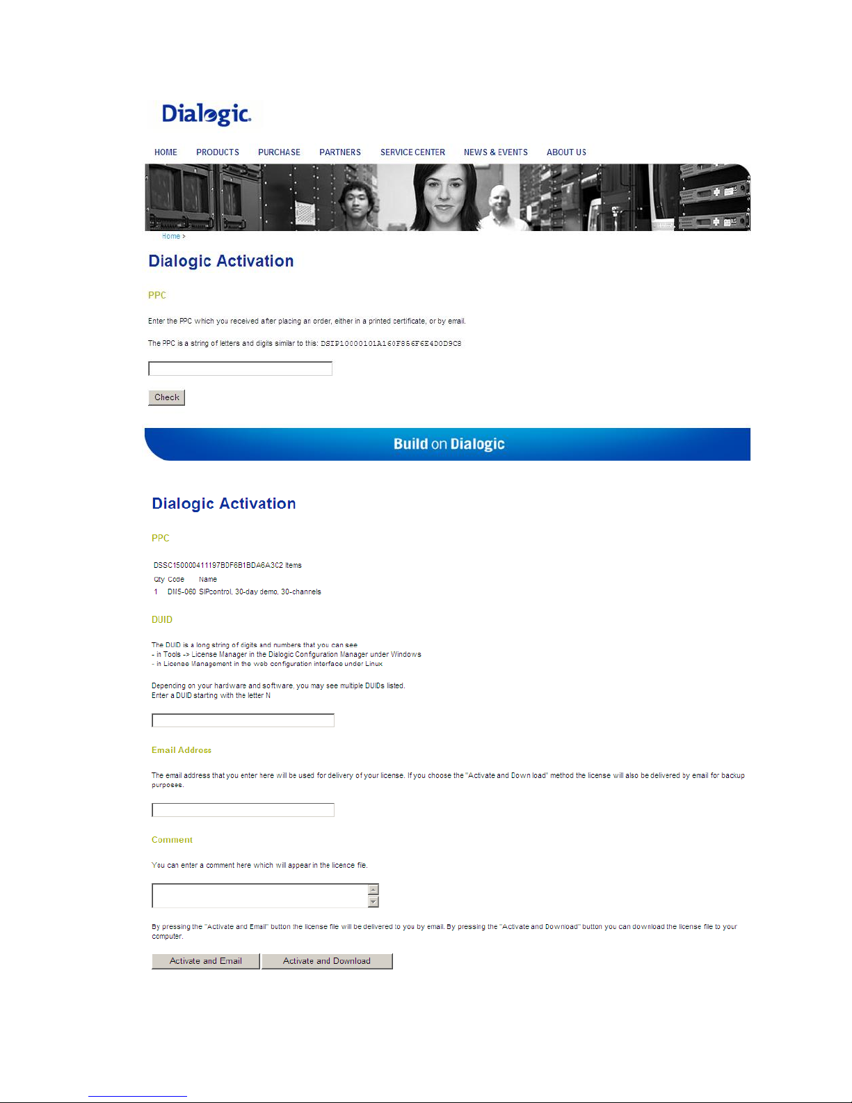
1. Open the following web site: http://www.dialogic.com/activate.
2. Enter your PPC and click Check:
12
Page 21
Initial Configuration and License Activation
3. If your PPC is valid, the following web site will open:
13
Page 22
Dialogic 4000 Media Gateway Series SU4.1 Reference Guide
4. Paste your Device Unique ID (DUID) that you saved earlier, and enter your email
address to which the license file should be sent.
5. Click Activate and Email to generate the license file that will be sent to the email
address you have entered.
6. Save the license file and activate it. For more information, see To Activate a License
File.
To Activate a License File
Note: The date set in the system settings of your computer must be correct. Otherwise,
you cannot add your license file.
Follow these steps to activate a license file:
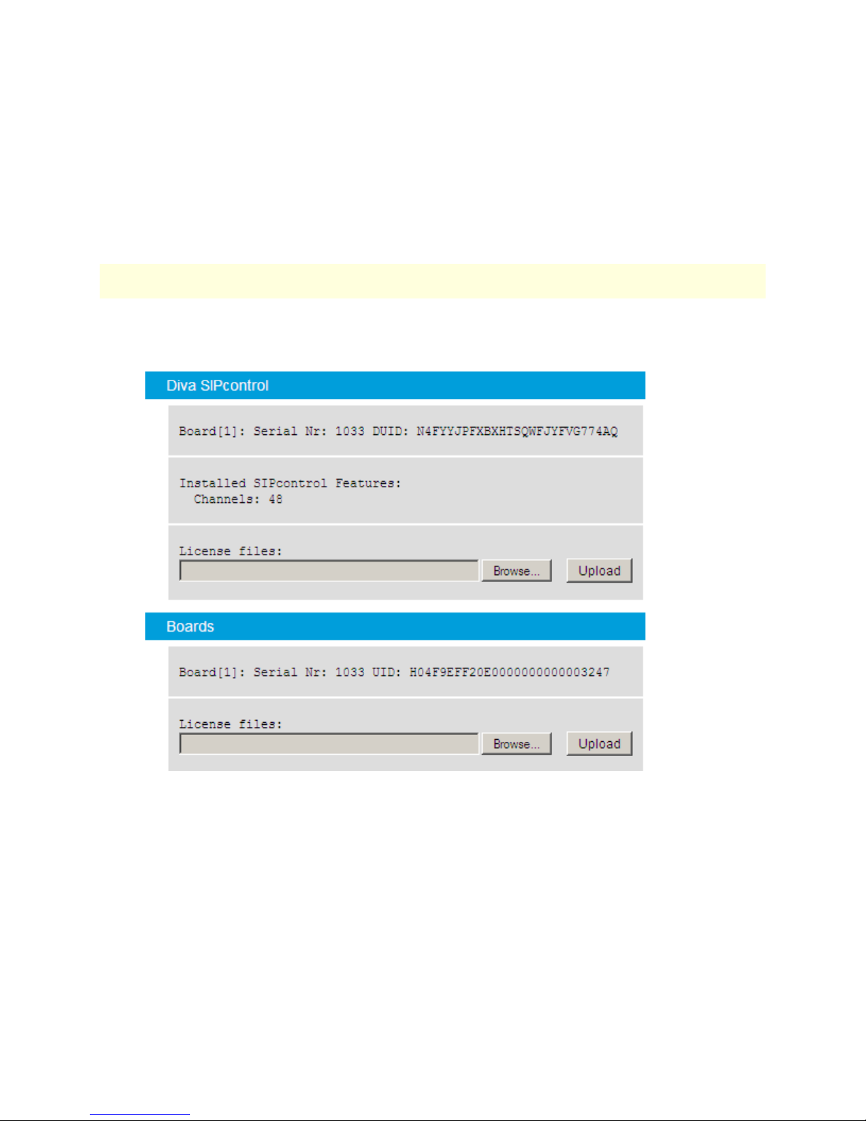
1. Click License Management on the left side of the Diva SIPcontrol web interface to
open the License Status dialog:
2. Upload the license file:
To upload a SIPcontrol license, click Browse in the Diva SIPcontrol section,
locate the directory in which you saved the SIPcontrol license file, and click
Upload.
To upload a fax or codec license, click Browse in the Boards section, locate
the directory in which you saved the fax or codec license, and click Upload.
14
Page 23
4. Dialogic® Diva® Media Board Configuration
Dialogic® Diva® Media Board Configuration
Since Diva SIPcontrol version 1.8, Diva Media Boards can be configured via the Diva web
interface. The configuration via the Diva web interface can be accessed and updated
remotely. The classic configuration via the Diva Configuration Manager is also available, but
it can only be accessed from the computer on which the Diva System Release software is
installed. Any changes will be reflected in both configuration tools, meaning that if you
change a parameter in the Diva web interface, the change is automatically done in the Diva
Configuration Manager as well (and vice versa). The update of the configuration between
both tools will only take effect after you have saved the configuration, and, in case of the
Diva Configuration Manager, after you activated the configuration. For more information
about activating the configuration, see the Diva Configuration Manager Online Help.
You can find information about the Diva web interface in Dialogic® Diva® SIPcontrol™
Configuration and in Configuration Tips and Hints.
Dialogic® Diva® Media Board Configuration via the
Dialogic® Diva® Web Interface
To configure Diva media boards via the Diva web interface, follow these steps:
1. Click Start > Programs > Dialogic Diva > SIPcontrol Configuration.
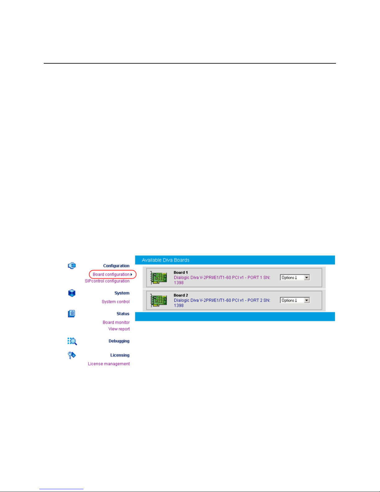
2. In the Diva web interface, click Board configuration on the left hand side. A page
displaying all installed Diva Media Boards opens:
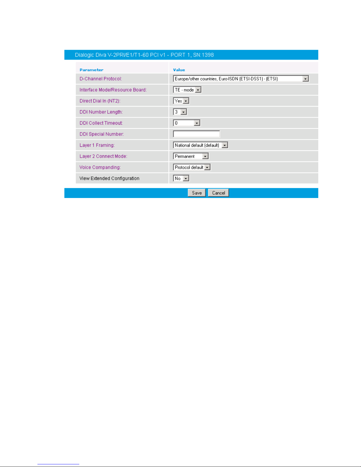
3. To configure Diva Media Board parameters, either click the board name or click the
down arrow and select Configuration. A page displaying the basic parameters will
open:
15
Page 24
Dialogic 4000 Media Gateway Series SU4.1 Reference Guide
Depending on the selected D-channel protocol, an additional menu opens in which you
can configure protocol-specific parameters.
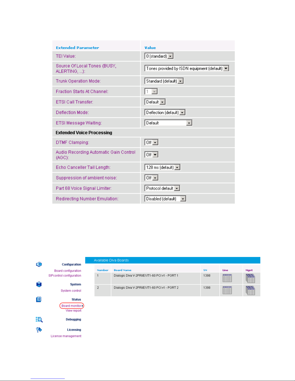
4. You can also configure extended parameters that depend on the D-channel protocol
you selected. To configure those parameters, select Yes under View Extended
Configuration. An additional menu will open:
16
Page 25
Dialogic® Diva® Media Board Configuration
5. To open the online help for a specific parameter, click the parameter, and a window
with the help text will appear.
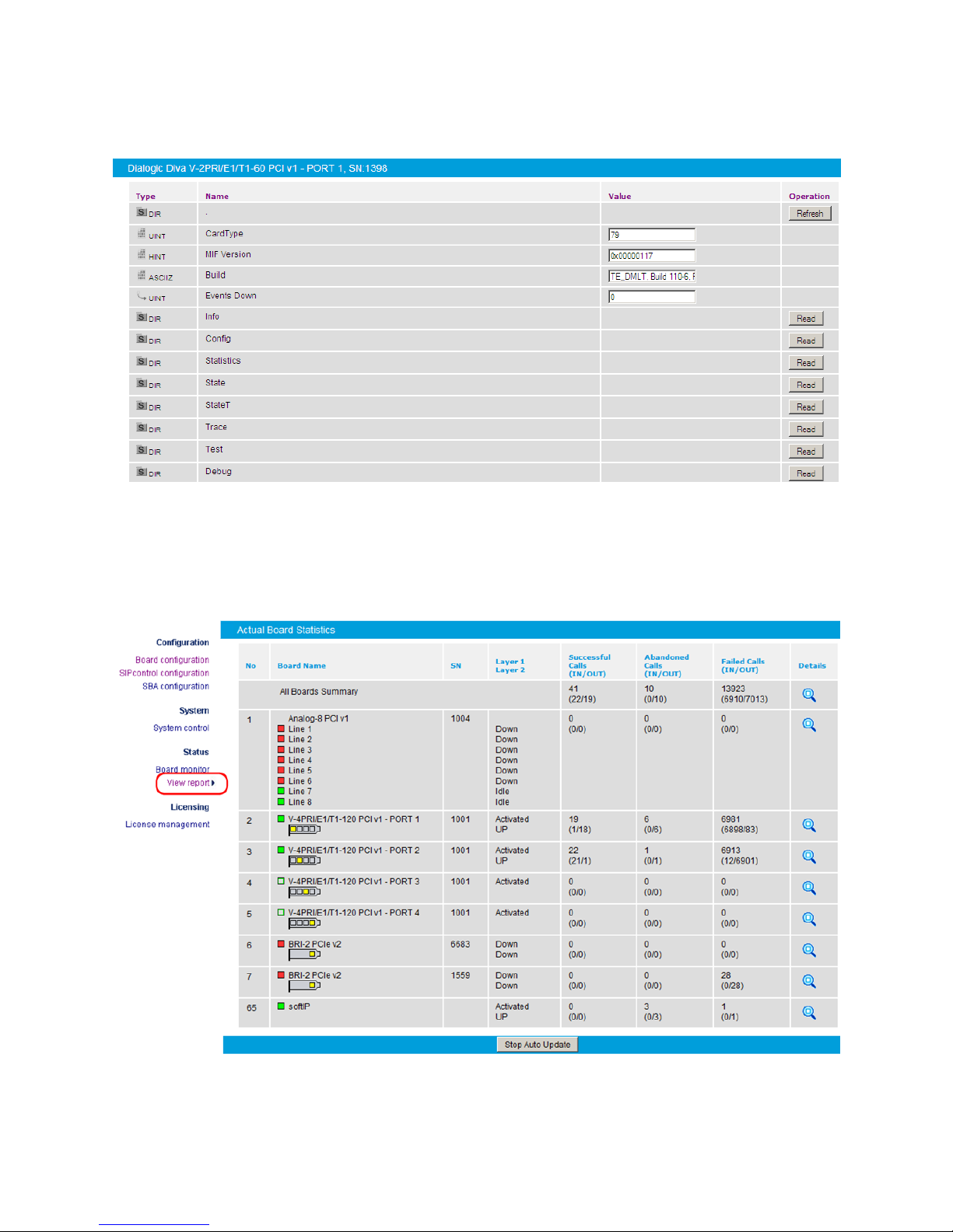
The Board Monitor
If you click Board monitor on the left hand side, a page opens that allows you to control
the current status and configuration of the installed Diva Media Boards, read internal board
trace buffers (XLOG), and gain access to the management interface of Diva Media Boards
and drivers:
17
Page 26
Dialogic 4000 Media Gateway Series SU4.1 Reference Guide
If you click the icon below the Mgnt column in the Available Diva Boards section, the
management interface browser opens:
The management interface browser allows you to navigate through the management
interface directories, and to read, write, and execute management interface variables using
the buttons in the Operation column.
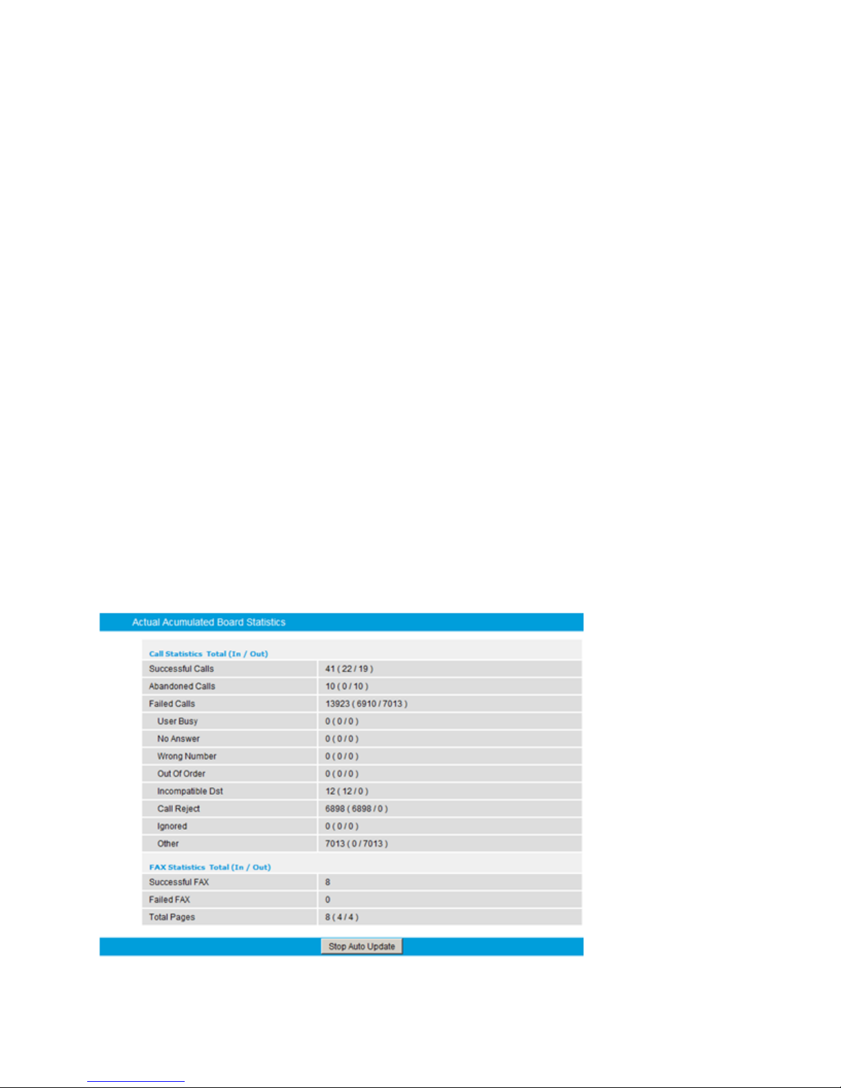
The View Report Option
If you click View report, the Actual Board Statistics page opens:
18
Page 27
Dialogic® Diva® Media Board Configuration
The Actual Board Statistics page displays the status of all Diva Media Boards and the
cumulative statistics for the active Diva Media Boards, including the number of failed,
successful, and abandoned calls. An abandoned call is a call that the caller ends before the
call was connected. For example, an abandoned call occurs when a call goes into the ringing
state, and the caller hangs up the phone before the called party replies with a "busy,"
"rejected," or "connected" signal.
A colored symbol in the Board Name column illustrates the line plug status:
Red: No signal; system is inactive.
Yellow: Remote synchronization error.
Green: System is active and functioning normally.
Click the plug status symbol to see additional information about the Layer 1 alarm state. For
example:
Green symbol on Analog board: "Cable detected"
Green symbol on ISDN board: "Layer 2 connected"
Red symbol on Analog board: "No cable detected"
Red symbol on ISDN board: "Layer 1 error"
If there is a Remote Yellow, Blue, or Red alarm condition, clicking the plug status symbol
shows a typical E1/T1 alarm message for the alarm. If two alarm conditions occur at the
same time, only the most critical alarm is displayed. For example, if a Red alarm condition
occurs at the same time as a Yellow alarm condition, only the Red alarm is displayed. If
Layer 2 is up, then Layer 1 is also up.
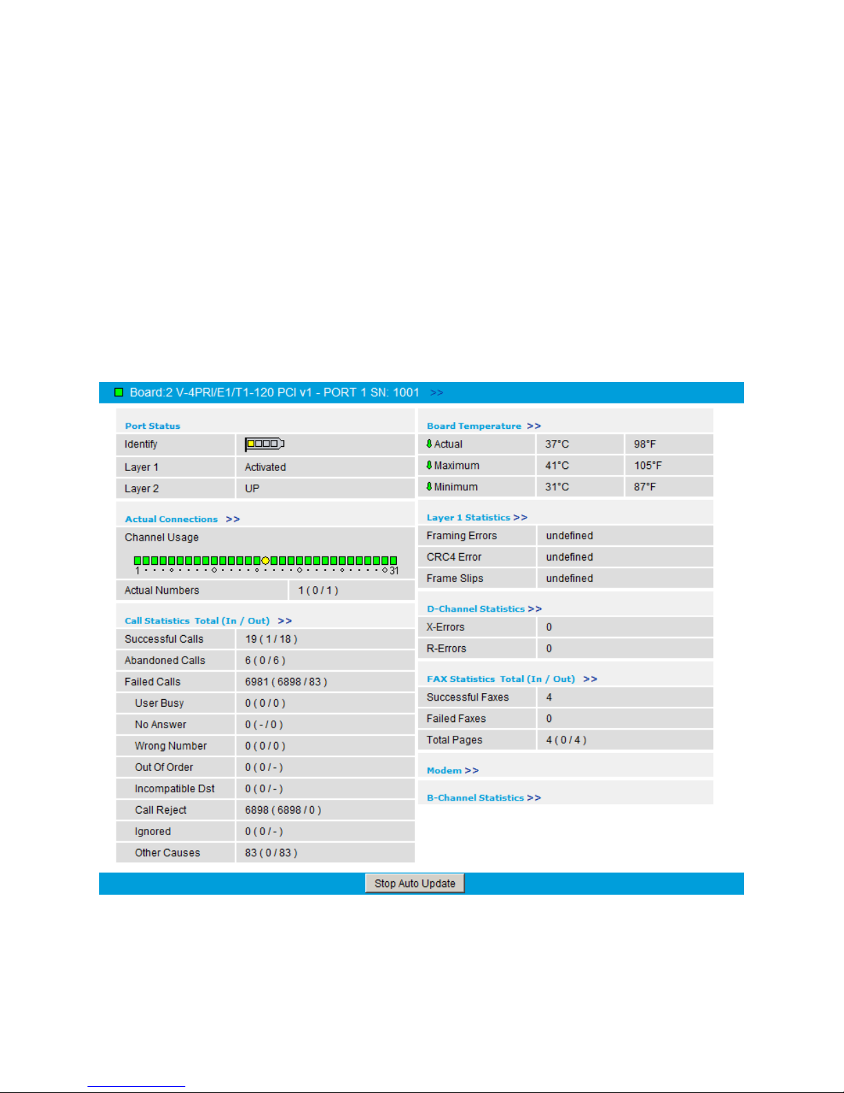
Displaying Cumulative Call and Fax Statistics
To display cumulative call and fax statistics for all Diva Media Boards, click the magnifying
glass at the end of the All Boards Summary row on the Actual Accumulated Board Statistics
page. The Actual Accumulated Board Statistics page opens.
19
Page 28
Dialogic 4000 Media Gateway Series SU4.1 Reference Guide
The displayed information includes the total number of successful, abandoned, and failed
calls, a summary of the most frequent call disconnect causes, the total number of successful
and failed fax calls, and the total number of fax pages received and sent. (In the
parentheses of the Total Pages field, the number of received faxes is on the left and the
number of sent faxes is on the right.) The information contained in the report originates
from the management interface of the Diva Media Boards
Displaying Board-Specific Details
To display details for a specific board, click the magnifying glass at the end of the associated
row on the Actual Accumulated Board Statistics page. The displayed information includes
the port status, channel usage, board temperature, and call and fax statistics. The
information contained in the report originates from the management interface of the Diva
Media Boards.
Details View for PRI or BRI Boards
The following screenshot shows the details view for a PRI board:
20
Page 29
Dialogic® Diva® Media Board Configuration
In the details view for PRI or BRI boards:
The Channel Usage display is correlated to the number of available channels. In this
example, because the PRI Board has 31 channels, the Channel Usage field shows 31
lamps — one for each channel.
The bracket symbol in the Port Status area shows the number of ports for the BRI or
PRI board. The highlighted port is associated with the Layer 1 and Layer 2 statistics
displayed below the bracket symbol.
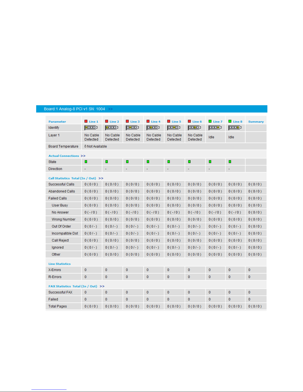
Details View for Analog Boards
The following screenshot shows the details view for an analog board:
21
Page 30

Dialogic 4000 Media Gateway Series SU4.1 Reference Guide
Supported Switch Types and Supported PBXs
Diva Media Boards currently support the following switch types:
Public Line ISDN Protocols
EMEA PRI and BRI
1TR6 (legacy Germany and old PBXs)
ETSI Australia variant (On Ramp ETSI)
ETSI (Europe, Africa)
ETSI Hong Kong variant
ETSI Serbia variant
ETSI Taiwan variant
ETSI New Zealand variant
INS-Net 64 / 1500 (Japan)
VN4 (legacy France, old PBXs)
VN6 (current France)
Line Side E1
Australian P2
Ericsson
Melcas
NEC
Nortel
R2 CAS (E1 only)
Argentina
Brazil
China
India
Indonesia
Korea
Mexico
Philippines
Thailand
Venezuela
22
Page 31

USA PRI and BRI
5ESS Custom (AT&T)
5ESS Ni Avaya (Lucent)
DMS 100 (Nortel)
EWSD (Siemens)
USA T1/PRI
4ESS
T1 RBS
Carrier Grade
ITU-T ISUP SS7
POTS
Worldwide POTS
PBX Protocols
Dialogic® Diva® Media Board Configuration
Generic QSIG T1 and E1
Note: The Generic QSIG switch type can be used for the majority of PBXs
ETSI
Note: Many European PBXs use the regular ETSI protocol (PRI and BRI).
Specific Major PBX Types
Alcatel 4200
Alcatel 4400
Alcatel 4410
ASCOM Ascotel 2020
ASCOM Ascotel 2030
ASCOM Ascotel 2050
ASCOM Ascotel 2060
DeTeWe OpenCOM 1000
Ericsson MD110/BP250
GPT Realitis iSDX
Lucent Definity
Matracom 6500
Nortel Meridian
Nortel opt11 Rev23
23
Page 32

Dialogic 4000 Media Gateway Series SU4.1 Reference Guide
Siemens Hicom 150
Siemens Hicom 300
Siemens Hipath 3000
Siemens Hipath 4000
Tenovis QSig
For a list of PBXs that are currently supported and tested with gateways from the different
Dialogic® Media Gateway Series, see http://www.dialogic.com/Solutions/Unified-
Communications/microsoft-pbx-interop-and-config-guides.aspx.
24
Page 33
5. Dialogic® Diva® SIPcontrol™ Configuration
Dialogic® Diva® SIPcontrol™ Configuration
This chapter describes how to configure Diva SIPcontrol. It provides configuration tips and
hints, includes general information about each configuration, and gives an overview of the
configurable Diva SIPcontrol parameters. The configuration of the Diva Media Boards is
described in Dialogic® Diva® Media Board Configuration.
About Dialogic® Diva® SIPcontrol™ Configuration
Diva SIPcontrol is configured via the Diva SIPcontrol web interface.
Opening the Dialogic® Diva® SIPcontrol™ Web Interface
To open the Diva SIPcontrol web interface, click Start > Programs > Dialogic Diva >
SIPcontrol Configuration. By default, access to the web interface is only allowed from
localhost (127.0.0.1), and the port number to which the server is listening is set to 10005.
If you need to access the configuration via remote access, you must set a password. To do
so:
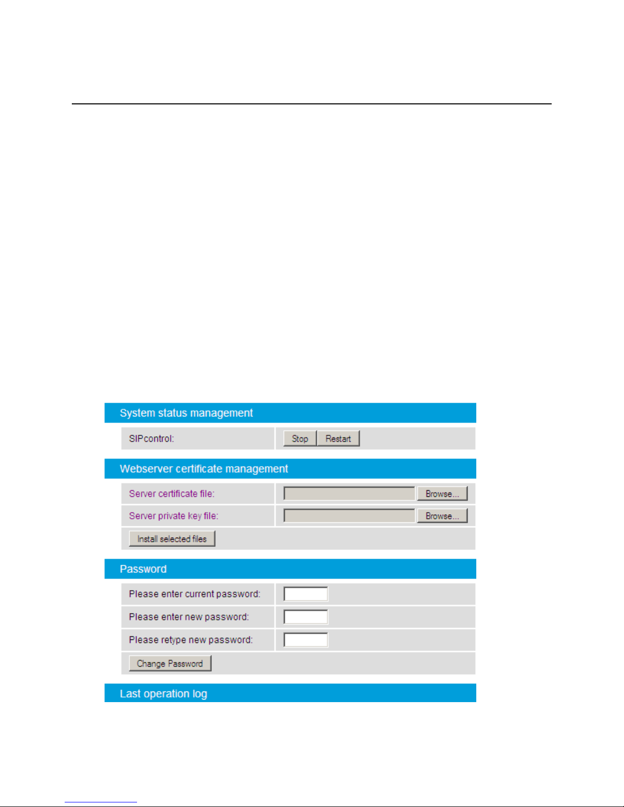
1. Click System control on the left side of the web interface.
The System control window appears:
25
Page 34

Dialogic 4000 Media Gateway Series SU4.1 Reference Guide
In the Password section, enter the current and new passwords, and then retype
the new password. A password must be seven digits or longer, and the use of
non-alphanumeric characters for a password is discouraged.
Click Change Password.
2. If necessary, open the port in the local firewall settings. To do this under Windows®
Vista, Windows® 7, Windows Server® 2008, or Windows 2008® R2, open the
command prompt with elevated rights.
Enter the following command on a 64-bit operating system:
netsh advfirewall firewall add rule name="Diva Webserver" dir=in
action=allow program="%ProgramFiles% (x86)\
Diva Server\DivaWebConfig.exe" protocol=tcp
Enter the following command on a 32-bit operating system:
netsh advfirewall firewall add rule name="Diva Webserver" dir=in
action=allow program="%ProgramFiles%\
Diva Server\DivaWebConfig.exe" protocol=tcp
You can now access the Diva SIPcontrol web interface on any of the IP addresses of the
computer where SIPcontrol is installed, and then you can configure the settings according to
your needs.
Dialogic® Diva® SIPcontrol™ Configuration Sections
Diva SIPcontrol configuration is divided into the following sections:
PSTN Interfaces
Network Interfaces
SIP Peers
Routing
Security Profiles
LDAP
Dialplans
Address Maps
Cause Code Maps
Codec Profiles
Registrations
Logging and Diagnostics
Configuration Tips and Hints
This section contains useful information about SIPcontrol configuration:
Changes to the configuration will only take effect after you click Activate
Configuration at the bottom of each configuration page.
The settings will be lost if you close the Diva SIPcontrol web interface without having
saved the configuration at the bottom of each configuration page.
26
Page 35

Dialogic® Diva® SIPcontrol™ Configuration
A restart of Diva SIPcontrol is recommended if you change the IP address or the port
on which SIPcontrol is listening. If you do not restart, Diva SIPcontrol will continue
listening on the previously configured port and IP address.
Note: The restart will terminate active connections.
The names for specific configuration elements are limited to 32 alphanumeric
characters and must not be repeated, i.e., you cannot assign the same name for two
SIP peers.
The configuration session times out after 30 minutes of inactivity and a new login is
required to access the session again. If the new login screen appears when you try
to save the configuration, login again and click the "Back" button of the browser. The
configuration session opens with the settings before the time out and you can save
the configuration.
To restart the Dialogic
click System control on the left hand side, and then click Restart in the System
status management section.
Diva SIPcontrol provides a secure configuration via the web interface (HTTPS). The
default port for HTTPS is 10006. Diva SIPcontrol provides a default certificate, but for
security reasons you can install your own webserver certificates. To install a
webserver certificate and corresponding key file, upload and install these files in the
Webserver certificate management section under System Control.
®
Diva® WebConfig service, in the SIPcontrol web interface,
To use TLS for SIP calls, you need to upload the certificates as described under
Security Profiles and enable the TLS port as described under Network Interfaces.
To open the online help for a specific parameter, click the parameter, and a window
with the help text will appear.
Configuring Dialogic® Diva® SIPcontrol™
At a minimum, a Diva SIPcontrol configuration must contain the following components:
At least one enabled network interface
At least one enabled SIP peer
At least one route for PSTN to SIP calls and another route for SIP to PSTN calls
There are four ways to configure Diva SIPcontrol:
Use the Configuration Wizard.
Load an existing configuration profile
Import an existing configuration file
Configure Diva SIPcontrol manually
Using the Configuration Wizard
The easiest way to configure Diva SIPcontrol is to use the Diva SIPcontrol configuration
wizard. The wizard provides a step-by-step interface that helps you generate configurations
for the following use cases:
Empty configuration that resets existing Diva SIPcontrol web interface settings
Simple configuration for a general purpose gateway
DMG4000 hybrid gateway
DMG4000 Survivable Branch Appliance
27
Page 36
Dialogic 4000 Media Gateway Series SU4.1 Reference Guide
The configuration prompts for the minimum required parameters.
To use the configuration wizard, follow these steps:
1. In the Overview section of the Diva SIPcontrol Configuration page, click Start
Configuration Wizard.
The configuration wizard asks whether you want the wizard to delete all unsaved
configuration changes.
2. Click OK.
3. Follow the configuration wizard prompts.
Loading an Existing Configuration Profile
Diva SIPcontrol configurations can be saved on the server as a configuration profile. You can
load an existing configuration profile to use the saved configuration settings.
To load a configuration profile, follow these steps:
1. From the web interface, click SIPcontrol configuration.
The SIPcontrol Configuration page appears.
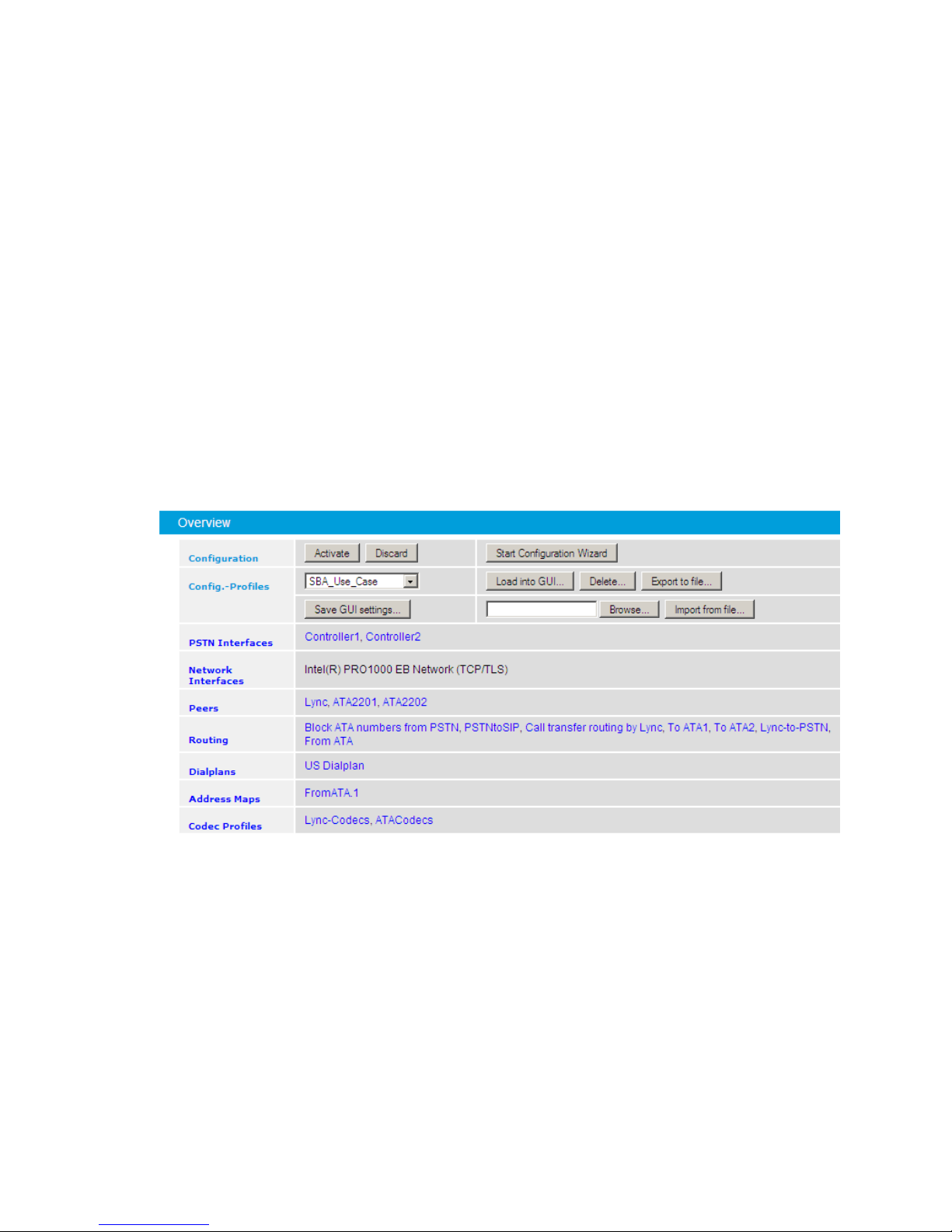
2. In the Overview section of the SIP Configuration page, access the Config.-Profiles
field, and select the configuration profile file you want to load:
3. Click Load into Gui.
A confirmation message appears, warning you that current GUI settings will be
overwritten.
4. Click OK on the message box to complete the load process.
5. Click Activate Configuration at the bottom of the SIPcontrol Configuration page to
use the loaded configuration.
Importing an Existing Configuration File
Diva SIPcontrol configurations can be exported to a file on the computer running the
browser. You can import an exported configuration file to use the saved configuration
settings.
28
Page 37
Dialogic® Diva® SIPcontrol™ Configuration
To import a configuration file, follow these steps:
1. From the web interface, click SIPcontrol configuration.
The SIPcontrol Configuration page appears.
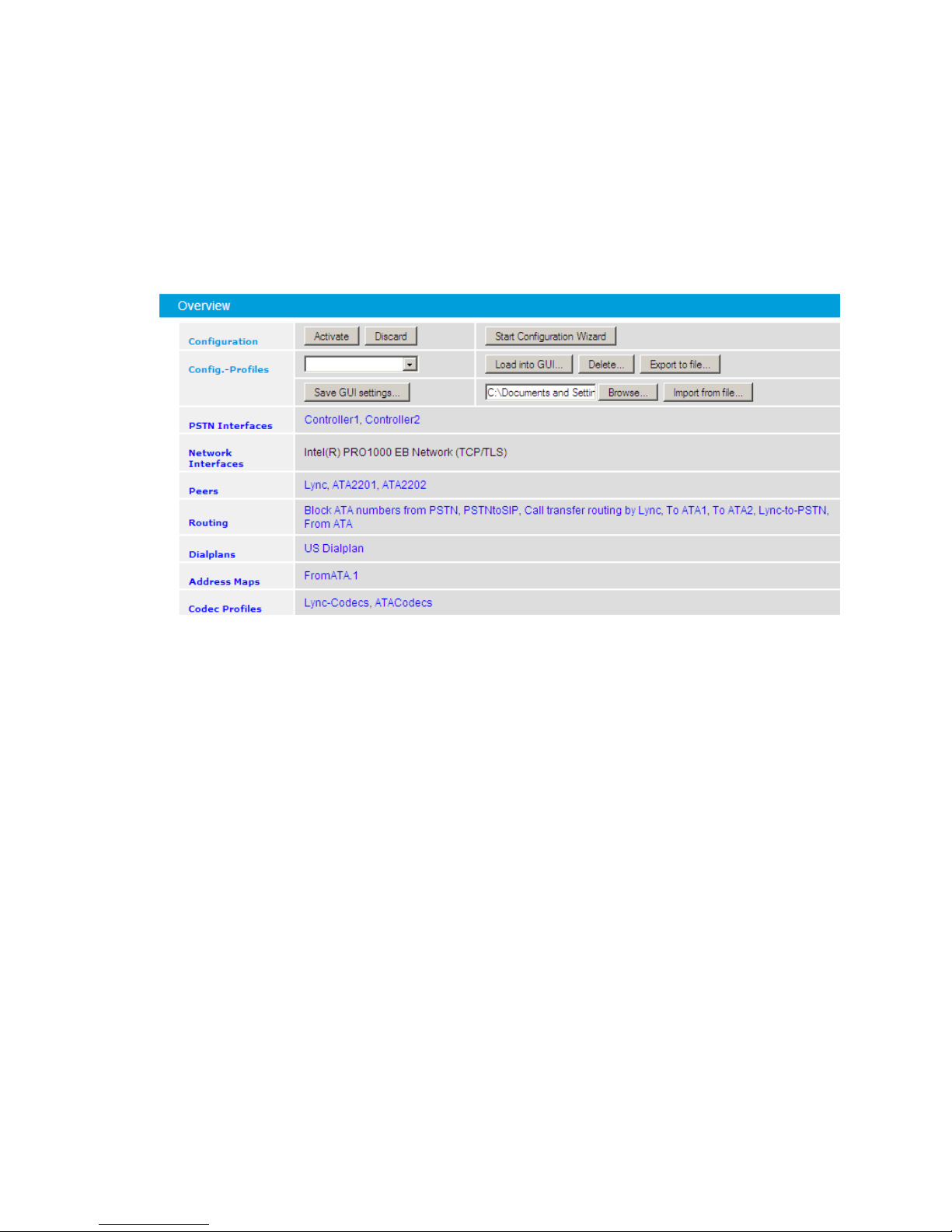
2. In the Overview section of the SIP Configuration page, access the Config.-Profiles
field, click Browse, and locate the configuration (.cfg) file you want to import:
3. Click Import from file.
A confirmation message appears, warning you that current GUI settings will be
overwritten.
4. Click OK on the message box to complete the import process.
5. Click Activate Configuration at the bottom of the SIPcontrol Configuration page to
use the loaded configuration.
Configuring Diva SIPcontrol Manually
To configure Diva SIPcontrol settings manually:
1. From the Diva SIPcontrol web interface, click SIPcontrol configuration.
The SIPcontrol Configuration page appears:
2. Configure each of the sections on the SIPcontrol Configuration page:
To expand a section, click on it.
To close a section, click the left arrow at the top right of the section.
To save the new settings, click Activate Configuration at the bottom of
each configuration page.
The portion of this chapter starting with PSTN Interfaces describes the settings in each
section of Diva SIPcontrol web interface.
29
Page 38

Dialogic 4000 Media Gateway Series SU4.1 Reference Guide
Saving Configuration Settings
Once you configure Diva SIPcontrol as desired, you can save the configuration settings for
future use. There are two ways to save the configuration settings:
Save the settings as a configuration profile on the server.
Save the settings by exporting them to a file on the computer running the browser.
Saving Configuration Settings as a Configuration Profile
To save the current configuration settings as a configuration profile on the server, follow
these steps:
1. Configure Diva SIPcontrol by following the instructions in this chapter.
2. In the Overview section of the SIP Configuration page, access the Config.-Profiles
field, and click Save GUI settings.
The Explorer User Prompt window appears.
3. Enter a name for the saved profile, and click OK.
The profile name now appears in the Config.-Profiles listbox.
Exporting Configuration Settings
To export current configuration settings to the computer running the browser, follow these
steps:
1. Configure Diva SIPcontrol by following the instructions in this chapter.
2. In the Overview section of the SIP Configuration page, access the Config.-Profiles
field, and click Export to file.
The File Download window appears, and asks whether you want to open or save the
file.
3. Click Save.
The Save As window appears.
4. Locate the directory where you want to save the file, enter a file name, and click
Save. Diva SIPcontrol uses the .cfg extension for exported files.
Deleting a Configuration Profile
To delete a configuration profile, follow these steps:
1. In the Overview section of the SIP Configuration page, access the Config.-Profiles
field, and select the profile you want to delete.
2. Click Delete.
A confirmation message appears.
3. Click OK on the confirmation message to delete the selected profile.
30
Page 39
Dialogic® Diva® SIPcontrol™ Configuration
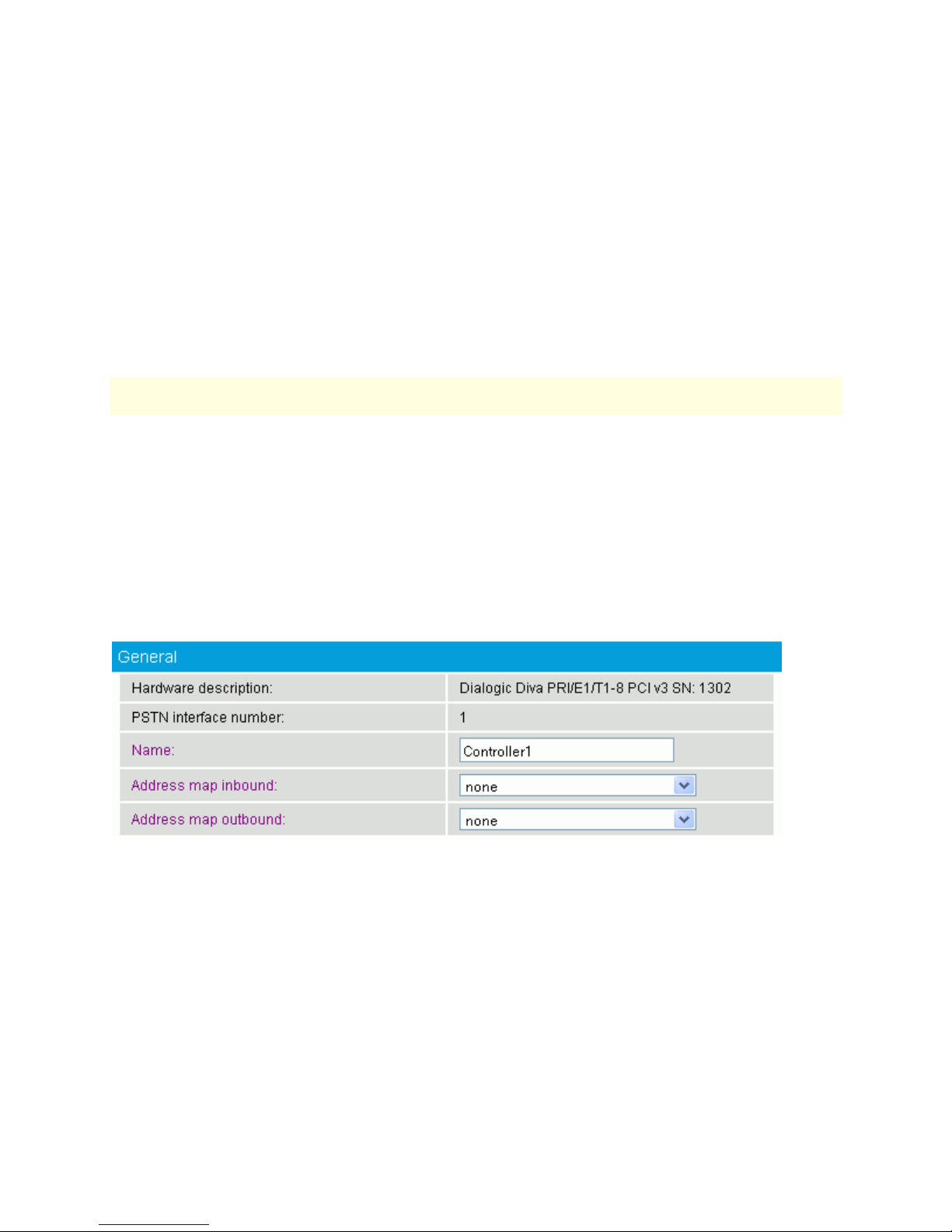
Hardware
description:
Displays the installed Diva Media Board. This entry is predefined by the
system and cannot be changed.
PSTN
interface
number:
Displays the number of the CAPI controller. The number is set
automatically by the system.
Name:
Displays the name of the installed Diva Media Board. The name can be
modified in order to display the purpose of the interface or the name of
the PBX to which the interface is connected.
PSTN Interfaces
This section describes Diva SIPcontrol's PSTN interface related settings, e.g., which lines are
used by Diva SIPcontrol or how call transfer is performed on this line. Line parameters such
as the signaling protocols (Q.Sig, ETSI) can be configured on the Board
Configuration page. For more information, see Dialogic® Diva® Media Board
Configuration.
At least one PSTN interface must be enabled for Diva SIPcontrol to be able to work.
Disabled PSTN interfaces are ignored for both inbound and outbound calls. For each line,
you can select a dialplan that you can configure as described in Dialplans.
To change the settings for the enabled interface, click the Details button on the right hand
side. To open the online help for a specific parameter, click the parameter, and a window
with the help text will appear.
Note: PSTN interfaces without a binding to the CAPI service in the Diva Configuration
Manager are disabled in the Diva SIPcontrol web interface and cannot be configured.
The following configuration menus are available for each Diva Media Board:
General
Enhanced
Address Normalization
Message Waiting Indication (MWI)
General
You can configure the following parameters in the General section when you create or
modify a PSTN interface:
31
Page 40

Dialogic 4000 Media Gateway Series SU4.1 Reference Guide
Address map
inbound:
Select the name of a regular expression list to be applied on calls
received on this interface. See Address Maps for more information about
setting up a regular expression list. If you upgraded from Diva
SIPcontrol version 1.5 or 1.5.1, an address map is automatically
generated here to provide the same number processing behavior in the
current Diva SIPcontrol version as in former Diva SIPcontrol versions. If
you used regular expressions in Diva SIPcontrol version 1.5.1, they will
be included in this address map as well, unless they cannot be converted
to the new scheme. In this case, the entry <Use Windows Registry
values> is available. Diva SIPcontrol will then use the regular
expressions defined in the registry keys that were used by Diva
SIPcontrol 1.5.1.
Regular expressions can be used to add or remove dial prefixes required
by a PBX or to rewrite public phone numbers with different number
ranges into a common format. See Address Map Examples for more
information.
Address map
outbound:
Select the name of a regular expression list to be applied on calls sent
out by this interface. See Address Maps for more information about
setting up a regular expression list. If you upgraded from Diva
SIPcontrol version 1.5 or 1.5.1, an address map is automatically
generated here to provide the same number processing behavior in the
current Diva SIPcontrol version as in former Diva SIPcontrol versions. If
you used regular expressions in Diva SIPcontrol version 1.5.1, they will
be included in this address map as well, unless they cannot be converted
to the new scheme. In this case, the entry <Use Windows Registry
values> is available. Diva SIPcontrol will then use the regular
expressions defined in the registry keys that were used by Diva
SIPcontrol 1.5.1.
Regular expressions can be used to add or remove dial prefixes required
by a PBX or to rewrite public phone numbers of different number ranges
into a common format. See the Address Map Examples for more
information.
Enhanced
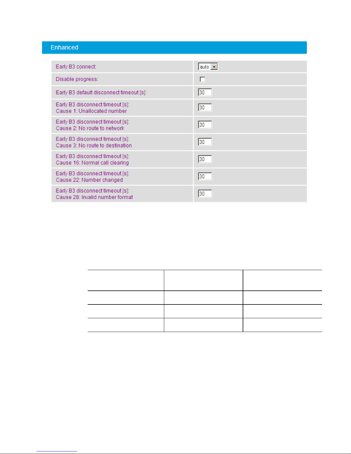
In the Enhanced section, you can configure the settings for early media support. Early
media refers to audio and video data that is exchanged before a session is accepted by the
called user. It can be unidirectional or bidirectional, and can be generated by the calling
party, called party, or both. Typical examples of early media generated by the called party
are ringing tone and announcements (e.g., queuing status). Early media generated by the
calling party typically consists of voice commands or DTMF tones to drive interactive voice
response (IVR) systems.
You can configure the following parameters in the Enhanced section when you create or
modify a PSTN interface:
32
Page 41
Dialogic® Diva® SIPcontrol™ Configuration
Early B3
connect:
With this parameter, you can determine if early media should be enabled on
this controller (EarlyB3) or whether early media should be enabled even if an
"inbound tones available" signal is not received from the PSTN.
The following values determine whether EarlyB3 and EarlyB3ForceMedia are
enabled:
Value
EarlyB3
EarlyB3Force
Media
auto
enabled
not enabled
on
enabled
enabled
off
not enabled
not enabled
The default value is auto.
Disable
progress
Disables the sending of PROGRESS messages to ISDN if a 183 Session
Progress message is received from the SIP peer.
This field is disabled by default.
33
Page 42
Dialogic 4000 Media Gateway Series SU4.1 Reference Guide
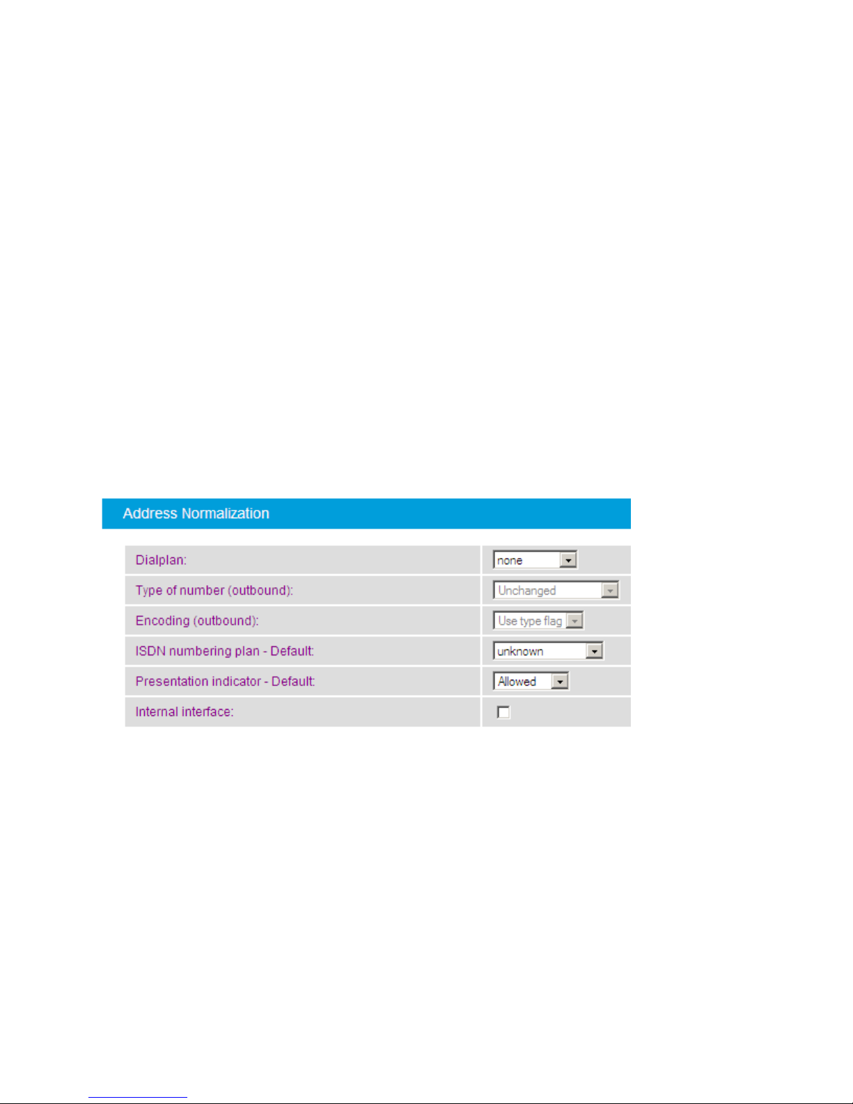
EarlyB3
default
disconnect
timeout [s]:
Specifies the disconnect timeout value for early media calls to the PSTN,
depending on the received cause value. The disconnect timer is released if a
call to the PSTN is terminated before the receiver answers the call. This allows
the caller to listen to a network announcement describing the reason for the
failure (e.g., "The number you have dialed is not available. Please try again
later.")
The default value is 30 seconds. This value also applies to all causes not listed
in the Enhanced section.
EarlyB3
disconnect
timeout [s]
Cause
<x>:<reason
for
disconnect
timeout>:
With these parameters, you can define the disconnect timeout for the
different disconnect timeout reasons. The default value for each reason is 30
seconds.
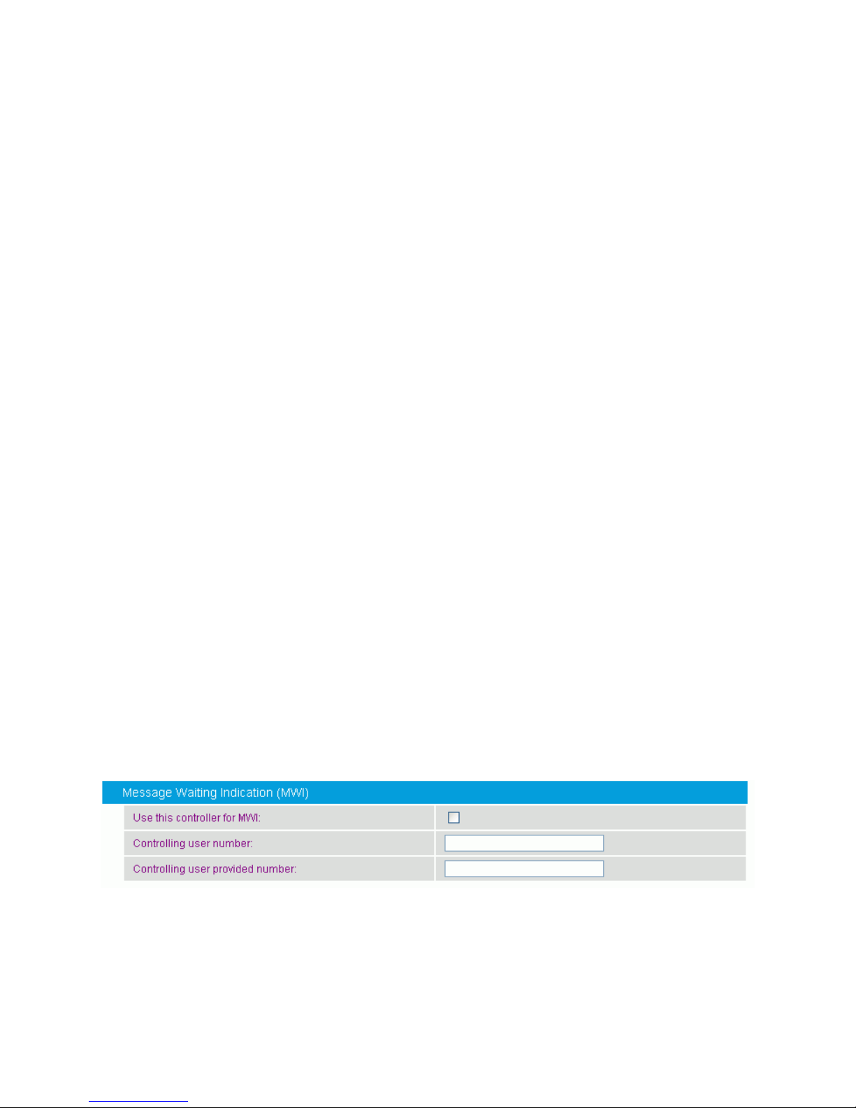
Dialplan:
Select the local dialplan to be used by the dialplan module of Diva
SIPcontrol. The selected dialplan applies only to this controller.
In most cases, the PSTN interfaces within the system share a common
dialplan of the local environment, but configuring the dialplan per
controller allows for handling variants, e.g., if the controllers are
connected to different PBXs or if one controller is directly connected to
the public network.
Configure the local dialplan as described under Dialplans before you
select it here.
Address Normalization
You can configure the following parameters in the Address Normalization section when
you create or modify a PSTN interface:
34
Page 43

Dialogic® Diva® SIPcontrol™ Configuration
Type of
number
(outbound):
This parameter determines the shortest format allowed in calls sent out
by this interface. You can modify this parameter only if you selected a
dialplan from the drop down menu. The following options are available:
Unchanged: The number type signaled on the received call request or
the type previously set via an inbound dialplan or address map will be
used unchanged for dialing.
International number: The number is always converted to an
international number, including country and area code.
National number: The number is converted to a national number
unless it is an international number with a different country code.
Extension: The number is reduced as much as possible. An internal
number is reduced to its extension only.
For more information about number formats, see Overview of How Call
Address are Processed.
Encoding
(outbound):
This parameter determines if numbers in calls sent out by this interface
should be encoded as unknown numbers with national or international
prefix digits, or as national or international numbers with type flags.
ISDN
numbering
plan Default
Change this setting only if the PBX rejects calls from Diva SIPcontrol
despite the dialed number being correct. This might occur, for example,
if the signaled numbering plan is not supported.
Presentation
indicator Default
If no presentation is specified via address rewriting, this parameter
specifies the presentation indicator to set on the calling party number
for calls to ISDN. The presentation indicator determines whether the
calling party number is shown or hidden from the called user.
This default does not apply to PSTN-PSTN calls, unless the known
presentation indicator is explicitly removed via an address map.
35
Page 44
Dialogic 4000 Media Gateway Series SU4.1 Reference Guide
Internal
interface:
This setting controls the usage of the outside access digit by the dialplan
in conjunction with this interface. If no outside access digit is configured
in the dialplan, this setting has no relevance. Basically, this setting
controls whether the outside access digit is expected in the called or
calling number depending on the call direction.
If this setting is enabled, the outside access digit is expected in
the called number for calls received on this interface and in the
calling number for calls sent by this interface.
If this setting is disabled, the outside access digit is expected in
the calling number for calls received on this interface and in the
called number for calls sent by this interface.
In most cases this setting is directly related to the NT/TE mode of the
interface. If the interface is in NT mode, this setting usually needs to be
enabled. If the interface is in TE mode or an FXO board is used, the
setting usually needs to be disabled.
If the Internal Interface option is enabled, calls to the connected
network will have a calling number with an outside access digit, unless
the calling party has an internal number or the number is converted to
the number type format instead of a number with a dialing prefix.
Also, the dialplan expects that calls from the connected network have a
called number with outside access digit, unless the called party has an
internal number. This expectation can be disabled in dialplan
configuration, if necessary.
If the option is disabled, calls to the connected network will have a
called number with an outside access digit, unless the called party has
an internal number or the number is converted to the number type
format instead of a number with dialing prefix.
Also, the dialplan expects that calls from the connected network have a
calling number with outside access digit, unless the calling party has an
internal number. This expectation can be disabled in dialplan
configuration, if necessary.
Message Waiting Indication (MWI):
You can configure the following parameters in the Message Waiting Indication (MWI)
section when you define or modify a PSTN interface:
36
Page 45
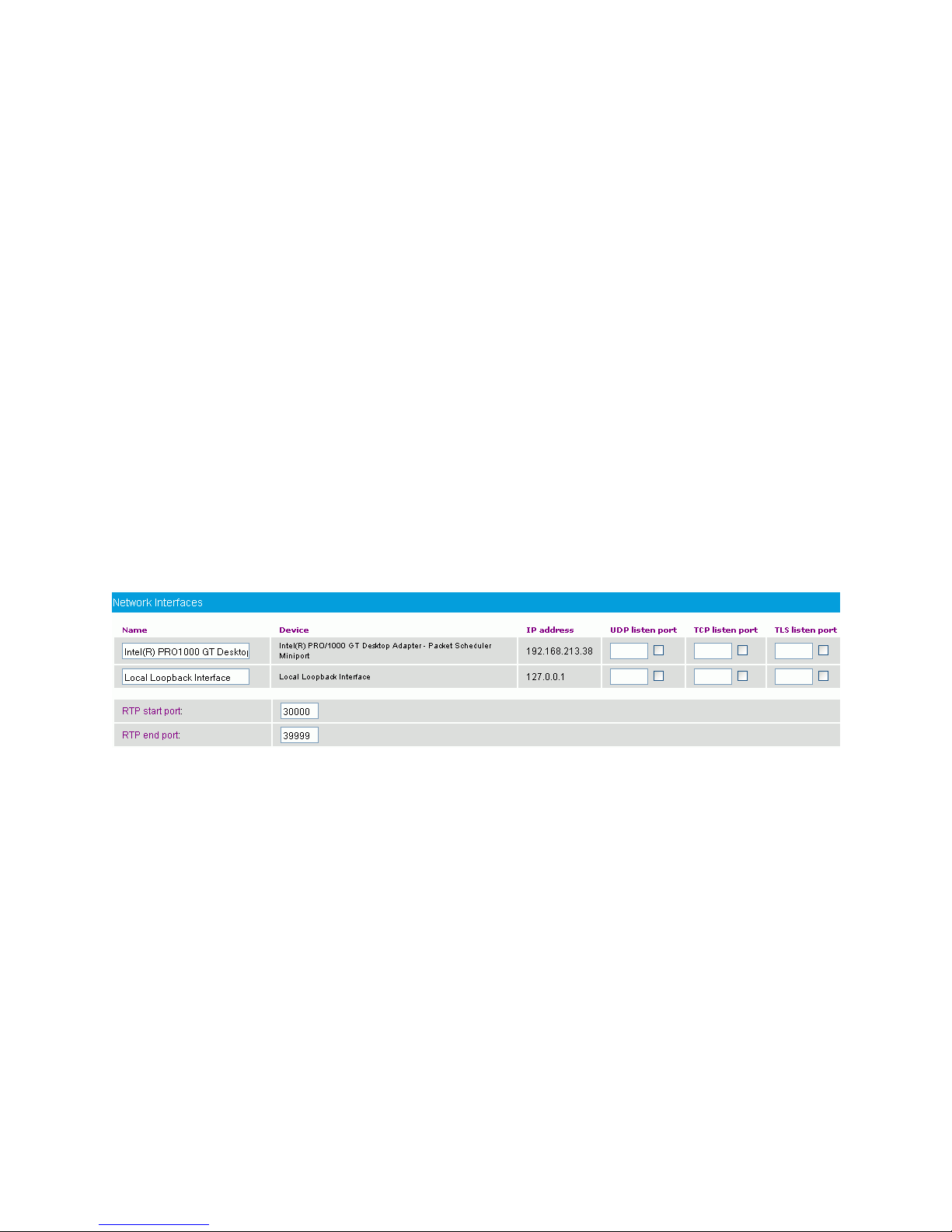
Dialogic® Diva® SIPcontrol™ Configuration
Use this
controller for
MWI:
The controller to use for MWI needs to be connected to a PBX port,
which allows for updating of the message waiting indication.
Controlling user
number:
A PBX typically requests an authentication to allow it to update the
message waiting indication. This authentication is done by a
Controlling user number. The administrator of the PBX can
provide this number.
Controlling user
provided
number:
The Controlling user provided number (CUPN) is the ISDN
number provided by the controlling user, that is, the ISDN number
of the originating user of the indicated message. Few PBXs require
the CUPN. The administrator of the PBX can provide more
information.
Name
Displays the name of the installed Ethernet adapter. The preset
designation can be replaced with a unique identifier, such as "Internal
Network".
Device
Displays the complete description of the installed Ethernet adapter
assigned by the operating system.
IP address
Displays the IP address of the computer on which Diva SIPcontrol is
installed.
UDP listen port
If you use UDP as the IP protocol for calls from SIP, enable the check
box to display the standard port number 5060. This standard port can
be used if no other SIP application is running on the same computer
as Diva SIPcontrol. Note that you can only enable one network
interface.
Network Interfaces
The Network Interfaces configuration allows for configuring the global network
parameters of Diva SIPcontrol, such as the IP addresses and the ports on which Diva
SIPcontrol will be listening. Diva SIPcontrol supports only a single IP address.
To open the online help for a specific parameter, click the parameter, and a window with the
help text will appear.
You can configure the following parameters when you define or modify a network interface:
37
Page 46

Dialogic 4000 Media Gateway Series SU4.1 Reference Guide
TCP listen port
If you use TCP as the IP protocol for calls from SIP, enable the check
box to display the standard port number 5060. This standard port can
be used if no other SIP application is running on the same computer
as Diva SIPcontrol. Note that you can only enable one network
interface.
TLS listen port
If you use TLS for encrypted calls, enable the check box to display
the standard port number 5061. You can change the port number,
but it must not be the same as the TCP Listen Port number. Note
that you can only enable one network interface. If you use TLS, you
need to upload security certificates and set the cipher level, as
described in Security Profiles.
RTP start port
Defines the lowest port of the range in which Diva SIPcontrol sends
and receives RTP streams. Change this value only if problems occur.
RTP end port
Defines the highest port of the range in which Diva SIPcontrol sends
and receives RTP streams. Change this value only if problems occur.
SIP Peers
A SIP peer is a specific endpoint to and from which Diva SIPcontrol will establish calls. The
peer-specific settings can be used to adapt Diva SIPcontrol's behavior towards this peer.
To add a SIP peer, click the Add button. To change the settings for the enabled SIP peer,
click the Details button on the right hand side. To open the online help for a specific
parameter, click the parameter, and a window with the help text will appear. The following
menus are available for configuration:
General
Enhanced
Security
Session Timer
Address Normalization
Authentication
General
You can configure the following parameters in the General section when you define or
modify a SIP Peer:
38
Page 47
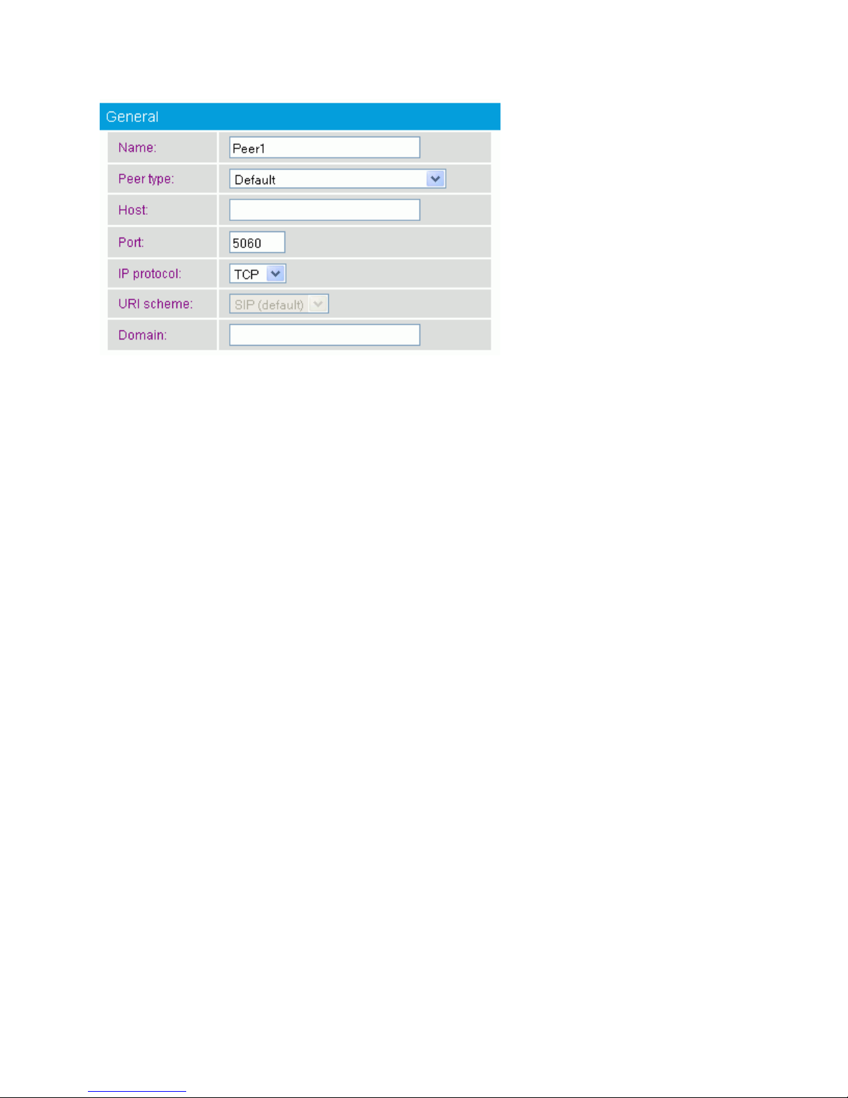
Dialogic® Diva® SIPcontrol™ Configuration
Name:
Enter a name for the SIP peer. A SIP peer is a specific endpoint to and
from which Diva SIPcontrol can establish calls.
Peer type:
SIPcontrol needs special workarounds to work properly with some SIP
peers, such as Microsoft® Exchange Server. If this is the case for your
configuration, select the specific SIP peer. If not, select Default.
Host:
Enter the host name or IP address of the peer. The name must be
resolvable by local name resolution. During the establishment of a call,
the host name is sent by this peer exactly as entered here, unless an
address map applies that converts the host name to a different format.
For more information about name resolution, see the Windows®
documentation.
Port:
Displays the SIP port on which the remote peer is listening. The default
is 5060, which is the standard port for SIP.
IP protocol:
Select the IP protocol to be used for calls to this peer. Calls from this
peer are accepted with all protocols and on all ports/addresses
configured in Network Interfaces.
If you selected:
MS Exchange 2007 or MS OCS 2007/2007 R2 - Mediation
Server as the Peer type, set the protocol to TCP.
MS Lync 2010 - Mediation Server as the Peer type, set the
protocol to TCP or TLS.
e-phone, as the Peer type, set the protocol to UDP.
39
Page 48
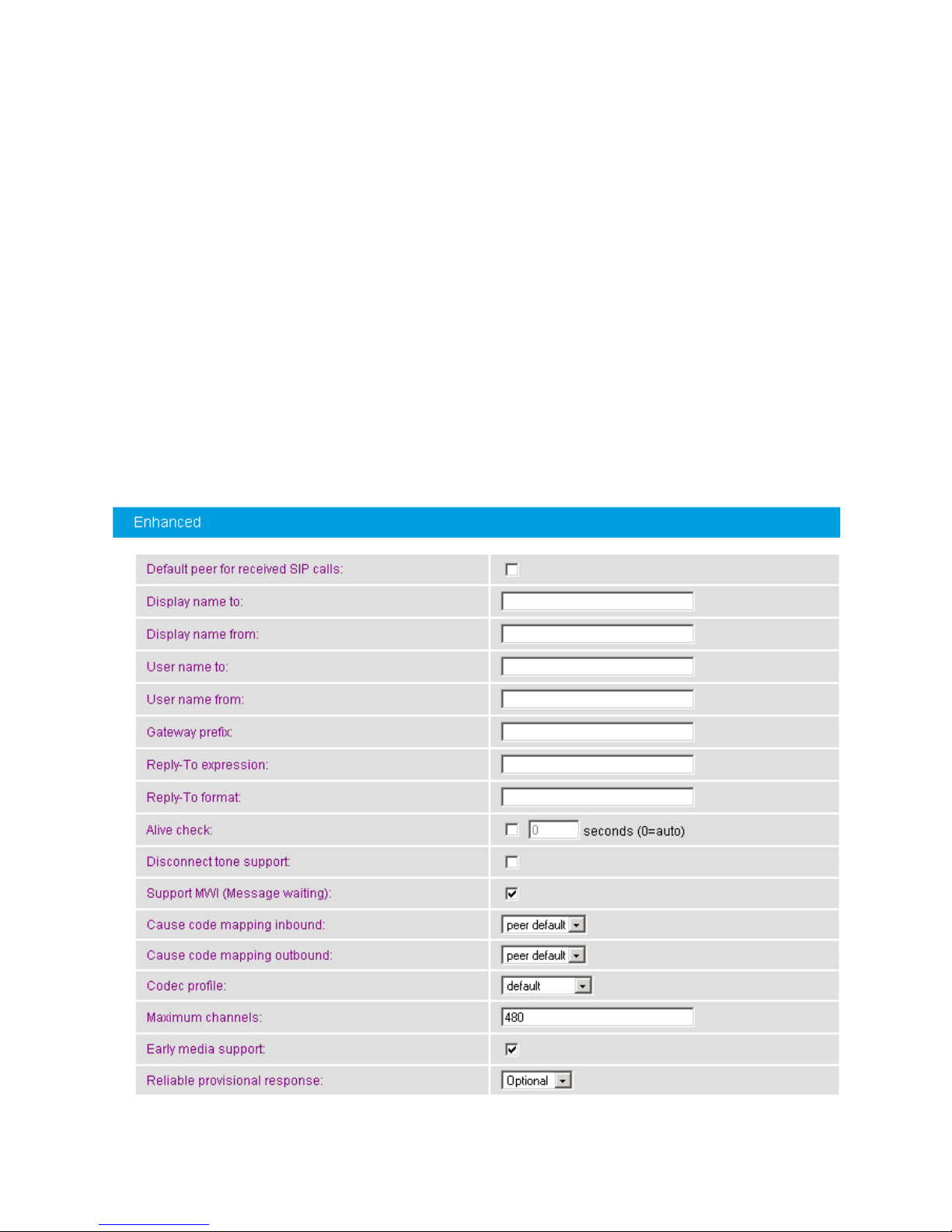
Dialogic 4000 Media Gateway Series SU4.1 Reference Guide
URI scheme:
This option is only available if you selected TLS as the IP protocol.
Calls are transmitted via various proxy servers. Some of them do not
transmit the calls as encrypted calls. If you select SIP (default), you
allow calls to be transmitted via proxy servers.
To make sure that a call is sent encrypted to the proxy of the remote
side, select SIPS (secure SIP). If the call is routed via a proxy server
that is not able to route the call encrypted, it rejects the call and the
call is sent to another proxy until it can be transmitted.
Domain:
Enter the domain name, e.g., dialogic.com, or the IP address. The
domain name must comply with the DNS rules. The domain name entry
here is only needed if the SIP peer does not use its hostname as the
source domain when it places a call.
Enhanced
You can configure the following parameters in the Enhanced section when you create or
modify a SIP Peer:
40
Page 49

Dialogic® Diva® SIPcontrol™ Configuration
Default peer
for received
SIP calls
Enable this option if the selected peer type should be used as the
default peer. Calls from unconfigured SIP peers will be assigned to
this peer, and therefore are handled with these settings. This option
can also be changed via the Default Peer option on the main
SIPcontrol page.
Note: When a peer is selected as the default, the previously selected
default peer is automatically unselected.
Display name
to:
Enter the name to be sent in the "To" header of the INVITE message
on calls from the PSTN to SIP.
Display name
from:
Enter the name that is to be sent in the "From" header of the INVITE
message on calls from the PSTN to SIP. To send the calling party
number include an asterisk (*) in the display name. For instance, if
the display name is "Dialogic *" and the calling number is 123, then
the remote side receives "Dialogic 123". To include an asterisk in the
display name, enter "\*". To include a backslash enter "\\".
User name to:
You can enter a user name in front of the host name, e.g.,
[email protected]. The user name is needed for the default route
when no called party number is transmitted, e.g., for Diva Analog
Media Boards.
If a call from SIP does not contain a user name, the name entered
here is transmitted to the receiver as the calling party number. This
applies to all references to PSTN in this section. (The opposite side can
either be PSTN or SIP.)
User name
from:
Enter the user name that is added to the SIP address when a number
from the PSTN is suppressed. You can also enter the complete SIP
address consisting of <username>@<local-IP/hostname>.
If a call from SIP does not contain a user name, the name entered
here is transmitted to the PSTN as the called party number.
Gateway
prefix:
You can configure this parameter only if you selected e-phone as
Peer type in the Edit SIP Peer Configuration window.
This prefix is added at the beginning of the address in the "Reply-To"
and "Contact" headers, which are copies of the "From" address. If this
string is not empty, the parameter "phone-context" will be added in
both headers.
Reply-To
expression:
You can configure this parameter only if you selected e-phone as
Peer type in the Edit SIP Peer Configuration window.
Enter the expression that may be necessary for the e-phone server to
handle the call. Normally, this is necessary to omit the 0 (zero) for
external calls and to manipulate the address so the e-phone server is
able to call back.
41
Page 50

Dialogic 4000 Media Gateway Series SU4.1 Reference Guide
Reply-To
format:
You can configure this parameter only if you selected e-phone as
Peer type in the Edit SIP Peer Configuration window.
Enter the format that may be necessary for the e-phone server to
handle the call. Normally, this is necessary to omit the 0 (zero) for
external calls and to manipulate the address so the e-phone server is
able to call back.
Alive check:
If you select this option, the failover procedure is expedited, because
Diva SIPcontrol does not wait for a call time-out if a peer does not
respond.
To achieve this, Diva SIPcontrol sends "pings" periodically to the peer
via OPTIONS requests. If the peer does not send a valid answer, it will
be treated as "inactive" and no calls will be routed to this peer until
the peer responds to the "pings.". In this case, Diva SIPcontrol will
automatically direct calls to this peer again.
Disconnect
tone support:
If the remote side is able to provide inband tones or signals on
disconnect, check here to play those inband tones to the SIP peer
instead of terminating the SIP call immediately. The SIP call ends
either by the client sending a BYE or after the Disconnect Timer of the
PSTN interface ends (normally with "Normal call clearing").
Normally this option is set only if the peer is a human talker.
Support MWI
(Message
waiting)
If enabled (the default), the SIP peer is able to receive Message
Waiting Indication (MWI) requests via a SIP NOTIFY message from
SIPcontrol.
If disabled, the destination for MWI requests is chosen from the
routing table. If no alternate destinations have been configured, the
request is declined.
Cause code
mapping
inbound:
Select the cause code mapping for calls coming from this SIP peer
that you configured under Cause Code Maps.
Cause code
mapping
outbound:
Select the cause code mapping for calls to this SIP peer that you
configured under Cause Code Maps.
42
Page 51

Dialogic® Diva® SIPcontrol™ Configuration
Codec profile:
Select the codec list that you configured under Codec Profiles. If you
do not select a list, an internal default list is used with the following
default priority order:
1. G.711A
2. G.711u
3. G.729, if licensed*
4. GSM-FR*
5. G.726 (16, 24, 32, and 40 kbps)*
6. Comfort Noise
7. T.38, if supported by the used Diva Media Board
8. DTMF via RFC 2833/RFC 4733 (no real codec, but internally
handled as codec)
In calls from SIP to the PSTN, the first codec offered by the peer that
is also in the set of supported and available codecs is selected. This
can be changed by a manual configuration that is not currently
available via the Diva SIPcontrol web interface.
*For Office Communications Server 2007, Office Communications
Server 2007 R2, and Lync Server, G.729, GSM-FR, and G.726 are
disabled by default.
Maximum
channels:
Specifies the number of channels that this SIP peer is able to handle
at the same time. This setting is used by Diva SIPcontrol to distribute
calls in a load-balancing scenario and to avoid speech quality
degradation and/or call failures at the peer due to overload conditions.
Early media
support:
Specifies whether the peer supports early media for calls to the PSTN.
For non-human callers, this option should be disabled.
Reliable
provisional
response:
SIP defines two types of responses, provisional and final. Provisional
responses provide information on the progress of the request
processing and final responses transmit the result of the request
processing.
This parameter specifies whether reliable provisional responses (RFC
3262) should be used. The following values are available:
Disabled: Reliable provisional response is not used.
Optional: Reliable provisional response can be used.
Required: Reliable provisional response is mandatory.
Security
You can configure the following parameters in the Security section when you define or
modify a SIP Peer:
43
Page 52
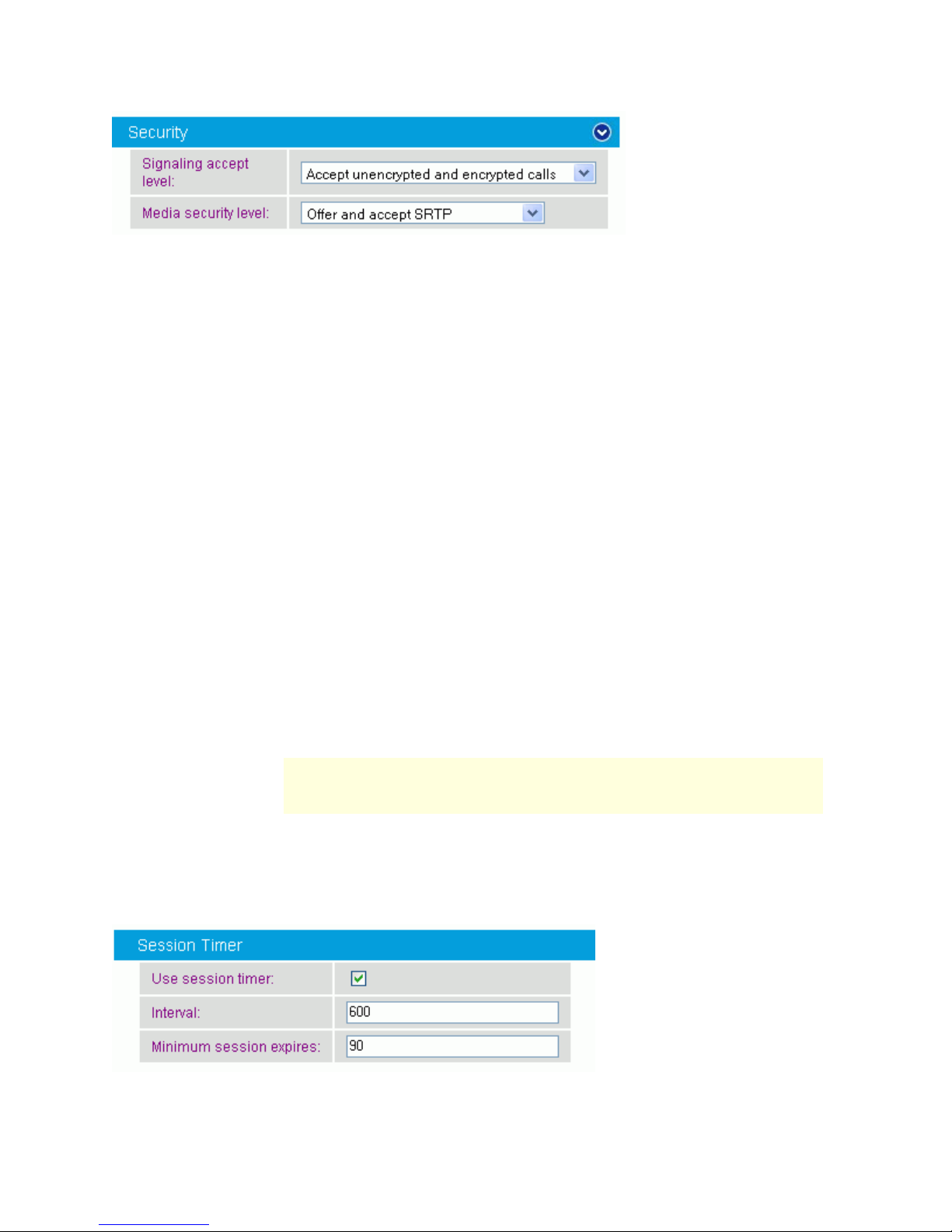
Dialogic 4000 Media Gateway Series SU4.1 Reference Guide
Signaling accept
level:
This parameter defines how call information should be accepted. To
accept encrypted calls, you need to activate TLS as listen port in
the Network Interfaces configuration.
Accept unencrypted calls only: Only signaling sent with
TCP or UDP is accepted. Any encrypted signaling is rejected.
Accept encrypted and unencrypted calls: All calls are
accepted, regardless of the encryption mode.
Accept encrypted calls only: Only signaling with TLS is
accepted; unencrypted signaling is rejected.
Accept encrypted call with SIPS URI only: Only
signaling encrypted with the URI scheme secure SIP is
accepted. Calls sent with TLS encryption are rejected.
Media security
level:
The Secure Real-time Transport Protocol (SRTP) authenticates
packets and encrypts data and thus adds security to the voice
stream. SRTP should be used together with TLS.
No SRTP: The voice stream is not secured with SRTP.
Offer and accept SRTP: The voice stream is secured with
SRTP, if possible.
Require SRTP for encrypted calls: Calls via TLS need to
use SRTP, otherwise they are rejected.
Require STP for all calls: All calls are established with
SRTP only, regardless of the signaling protocol.
Note: If you select Require SRTP for encrypted calls, calls
without SRTP are still allowed via UDP or TCP, unless Signaling
accept level does not allow calls via UDP or TCP.
Session Timer
You can configure the following parameters in the Session Timer section when you define
or modify a SIP Peer:
44
Page 53
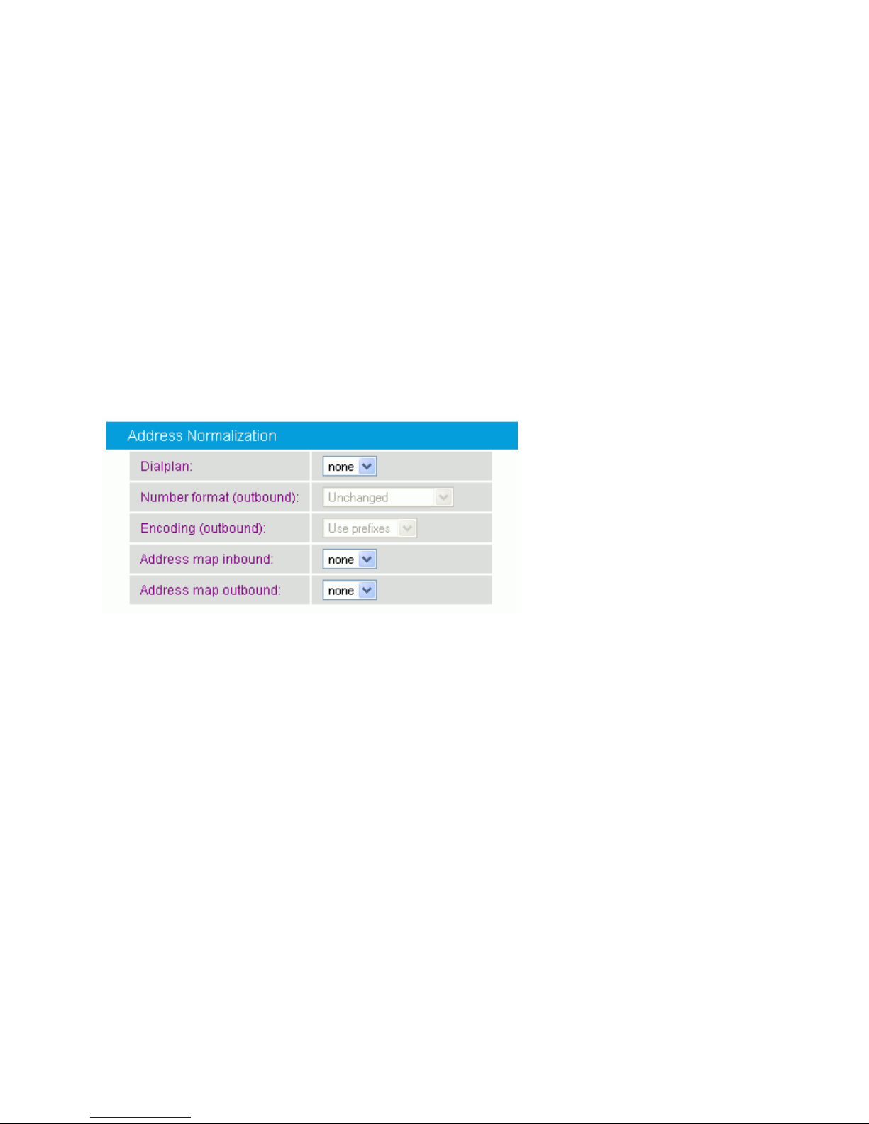
Dialogic® Diva® SIPcontrol™ Configuration
Use session
timer:
Activates session monitoring via SIP session timers using the time-out
values given here. Refer to RFC 4028 for details.
Interval:
If Use session timer is enabled, you can set a time-out in seconds
until a call is considered to be aborted. Refreshes are normally
performed after the first half of the interval has elapsed. The minimum
value is 90 seconds. The default value is 600 seconds.
Minimum
session
expires:
If Use session timer is enabled, you can set a time in seconds
between two session refresh messages that Diva SIPcontrol will accept.
The minimum value is 90 seconds.
Dialplan:
Select the local dialplan to be used by the dialplan module of Diva
SIPcontrol. Configure the local dialplan as described in Dialplans,
before you select it here.
The dialplan selected here applies only to outgoing calls.
Number
format
(outbound):
This parameter determines the shortest format allowed that is sent in
calls to this SIP peer. You can modify this parameter only if you
selected a dialplan from the drop down menu. The following options
are available:
Unchanged: The number signaled in the SIP message will be used
unchanged for dialing.
International number: The number is always converted to an
international number, including country and area code.
National number: The number is converted to a national number
unless it is an international number with a different country code.
Extension: The number is reduced as much as possible. An internal
number is reduced to its extension only.
For more information about number formats, see Number Modification
Using Address Maps.
Address Normalization
You can configure the following parameters in the Address Normalization section when
you define or modify a SIP Peer:
45
Page 54
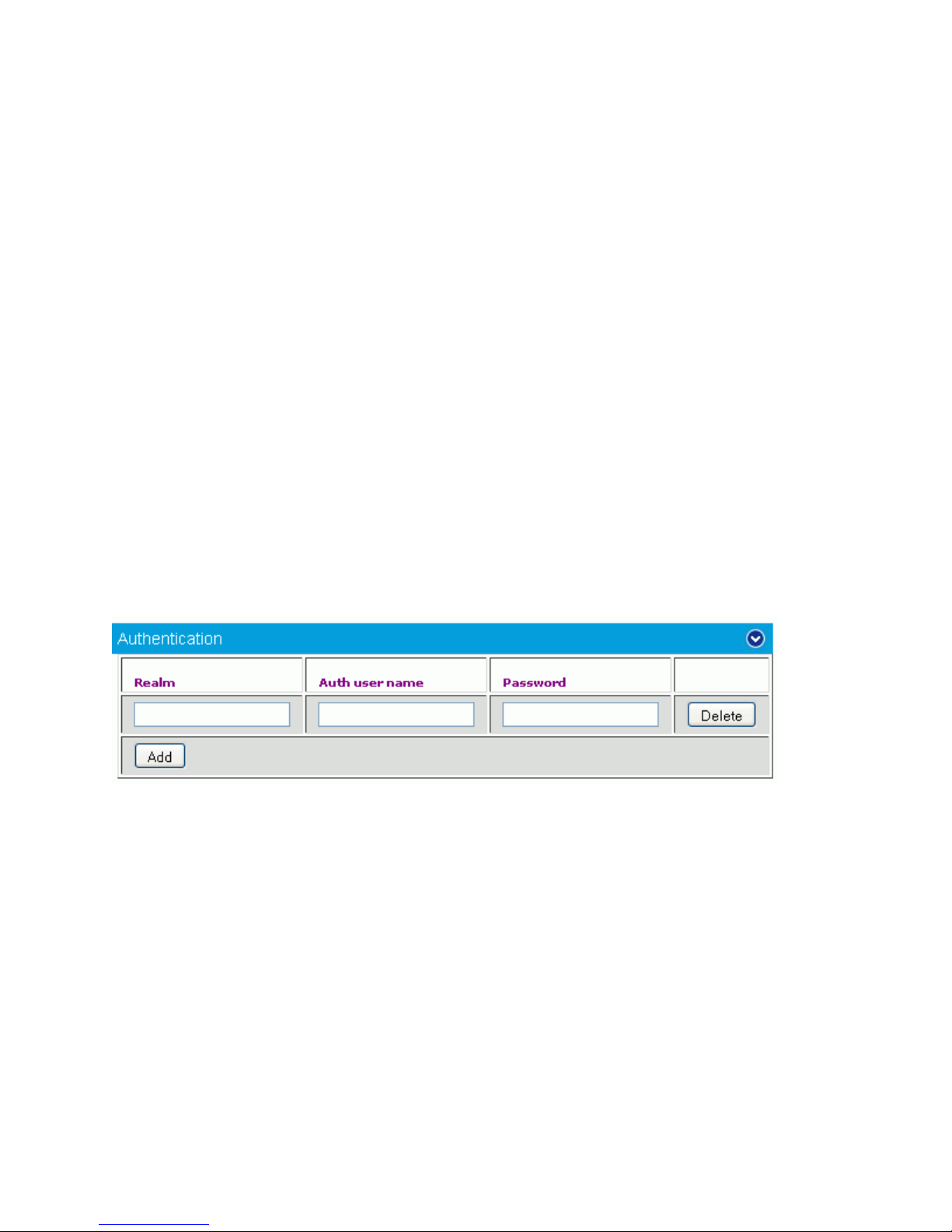
Dialogic 4000 Media Gateway Series SU4.1 Reference Guide
Encoding
(outbound):
Determines if numbers in calls to this SIP peer should either be
encoded as unknown numbers with national or international prefix
digits or as national or international numbers with type flags.
Address map
inbound:
Name of the regular expressions list applied to the addresses received
on calls from this SIP peer. See Address Maps for more information
about setting up a regular expression list.
Regular expressions can be used to add or remove dial prefixes
required by a PBX or to rewrite public phone numbers of different
number ranges into a common format. See Number Modification Using
Address Maps for more information.
Address map
outbound:
Select the name of a regular expression list to be applied on calls to
this SIP peer. See Address Maps for more information about setting up
a regular expression list.
Regular expressions can be used to add or remove dial prefixes
required by a PBX or to rewrite public phone numbers of different
number ranges into a common format. See the Number Modification
Using Address Maps for more information.
Realm:
A realm is a protection domain with its own user names and
passwords. Enter the realm used by the SIP peer for authentication.
The realm entered here needs to be the same as the realm of the
endpoint.
Auth user
name:
Enter a user name to be used with this realm.
Password:
Enter the password to be used with this realm.
Authentication
You can configure the following parameters in the Authentication section when you define
or modify a SIP Peer:
46
Page 55
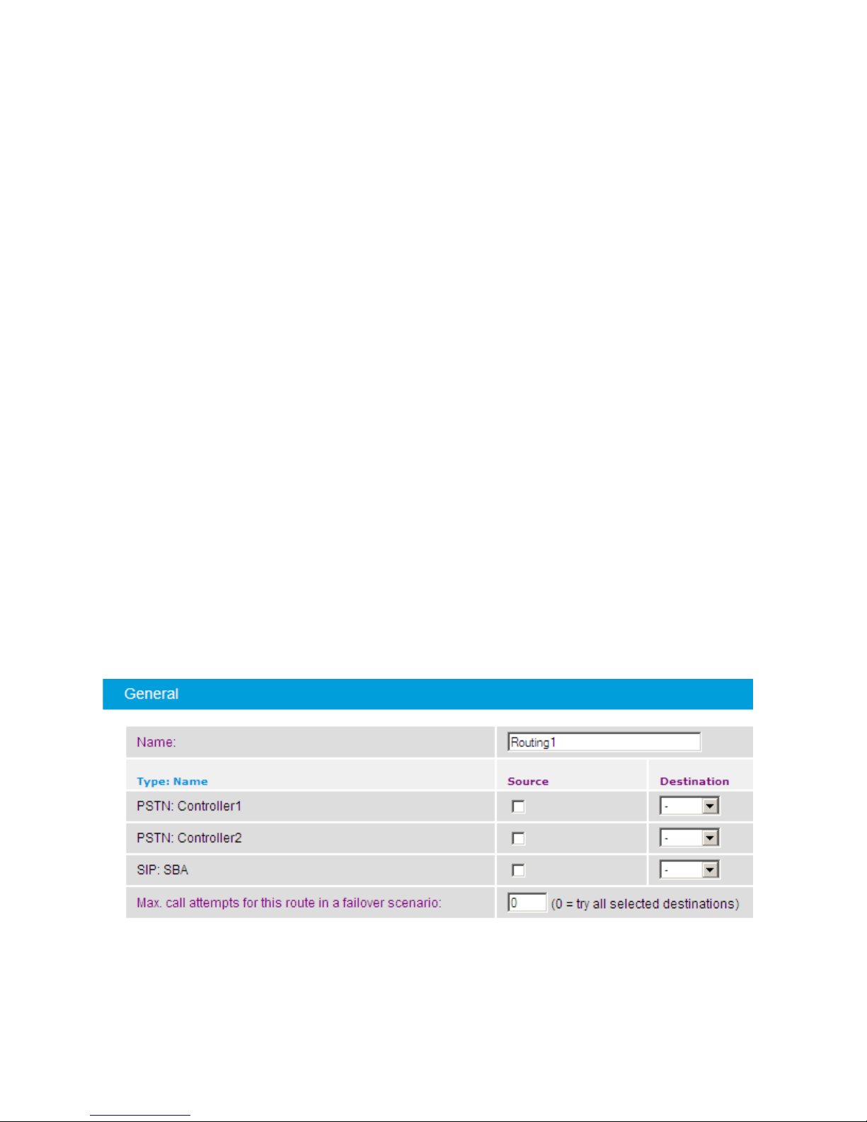
Dialogic® Diva® SIPcontrol™ Configuration
Routing
The Routing configuration defines the destination to which incoming calls are forwarded.
Possible criteria that can determine the destination are:
Called, calling, and redirected number or SIP address of a call for which the
redirected number is only available for calls originating in the PSTN.
The source from which a call originated, i.e., a PSTN interface name or a specific SIP
peer.
The current channel allocation across a set of several possible destinations in a load-
balancing environment.
The current status of a destination. See How Calls Are Processed for more
information.
The result of an Active Directory query.
To add a route, click the Add button. To change the settings for the enabled route, click the
Details button on the right hand side. Since routes are processed in their configured order,
the first matching route takes the call. To change the order, click the "arrow up" and "arrow
down" buttons. To open the online help for a specific parameter, click the parameter, and a
window with the help text appears.
For more information about possible route configurations, see Routing Examples.
The following menus are available for configuration:
General
Address Normalization For Condition Processing (Using Source Dialplan)
Conditions
Address Manipulation
General
You can configure the following parameters in the General section when you define or
modify a route:
47
Page 56
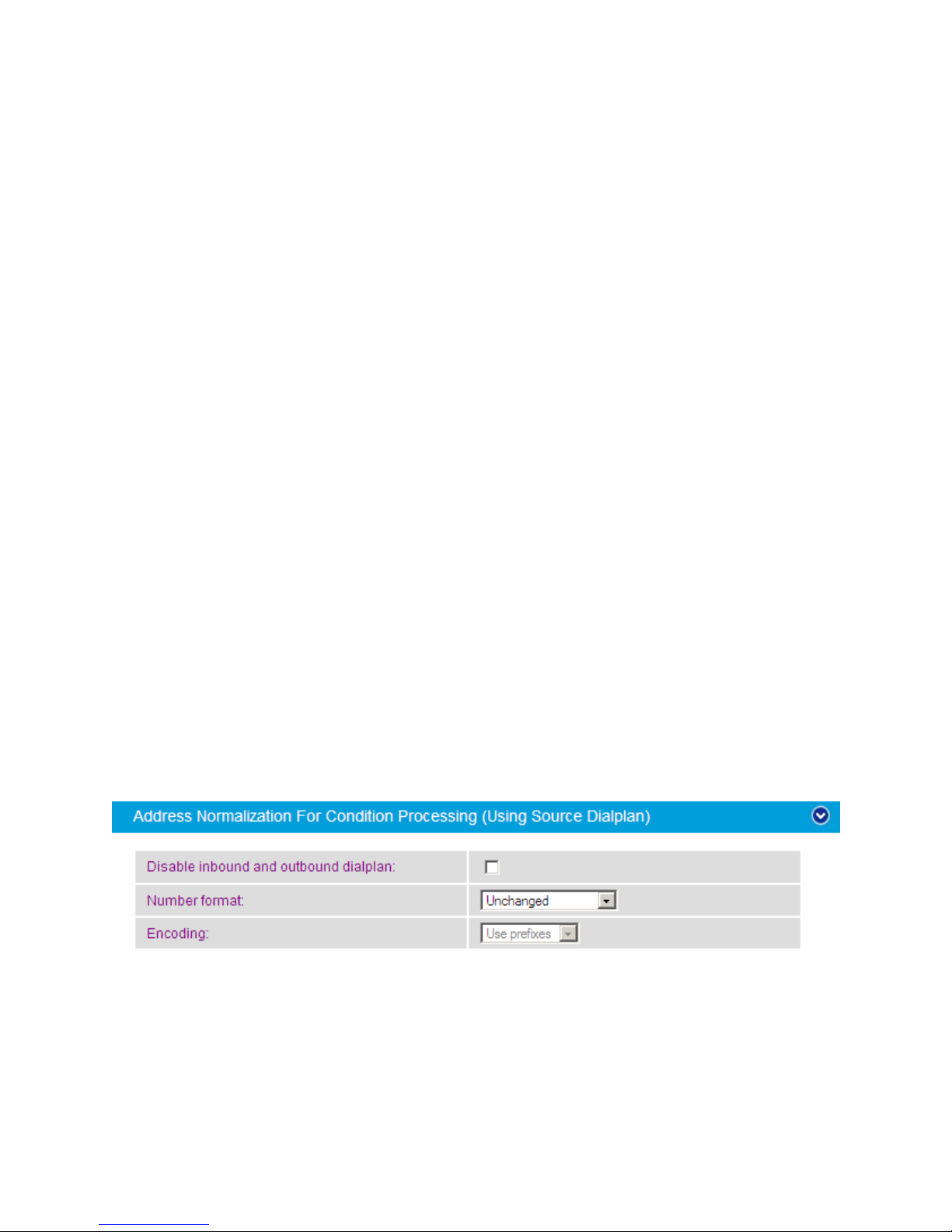
Dialogic 4000 Media Gateway Series SU4.1 Reference Guide
Name:
Enter a unique name for the route, e.g., "Calls to MS Exchange
Server".
Source:
Select either the configured PSTN interfaces or SIP peer as a source.
The route will only be considered for a call if the call originated from a
selected source.
You can select the same interface as a source and destination, e.g., if
a call from the PSTN should be routed back to the PSTN.
Calls arriving at disabled sources are immediately rejected without
querying any route.
At least one source interface is required for the route.
Destination:
The master or slave option in the dropdown menu allows for
configuring priorities. Diva SIPcontrol will always try to establish a call
to one of the masters first and considers the slaves only if all masters
have failed or could not accept calls due to their call load.
Maximum call
attempts for
this route in a
failover
scenario:
Enter the maximum number of destinations in a route that Diva
SIPcontrol should call in a failover environment. If you enter 0 (zero),
Diva SIPcontrol tries all selected destinations. A value of 1 disables the
failover functionality and tries only the first destination of a route.
If LDAP is used and the LDAP query requires various call attempts, this
counts only as one call attempt in a failover environment, because the
LDAP queries are not counted as call attempts here but in a different
instance.
Address Normalization For Condition Processing (Using Source
Dialplan)
You can configure the following parameters in the Address Normalization For Condition
Processing (Using Source Dialplan) section when you define or modify a route:
48
Page 57

Dialogic® Diva® SIPcontrol™ Configuration
Disable
inbound and
outbound
dialplan:
This parameter defines whether the interface-specific inbound and
outbound dialplans should be disabled for the route being defined. If
you select this parameter, neither the inbound nor outbound dialplan is
applied, and only the address maps are used for the numbers.
Disable this parameter for emergency numbers such as 911 in the U.S.
and 110 in Germany, because these numbers can falsely be converted
to E.164 using a dialplan. To be sure that special numbers like
emergency numbers pass unchanged, you should also define special
break-out rules for these numbers in the address maps.
Note: If Disable inbound and outbound dialplan is enabled, the Number
format and Encoding parameters will not be evaluated.
Number
format:
This parameter determines the shortest format allowed in calls using
this route. If the source interface of the call has no dialplan assigned,
this setting has no effect. The following options are available:
Unchanged: The number signaled in the received call request will be
used unchanged for dialing.
International number: The number is always converted to an
international number, including country and area code.
National number: The number is converted to a national number,
unless it is an international number with a different country code.
Extension: The number is reduced as much as possible. An internal
number is reduced to its extension only.
For more information about number formats, see Number Modification
Using Address Maps.
Encoding:
Determines if numbers in calls using this route should be encoded either
as unknown numbers with national or international prefix digits or as
national or international numbers with type flags.
Conditions
You can configure certain conditions for a route. A route can only be matched if the three
condition parts (called number, calling number, and redirect number) match their call
address counterpart in any of the lines. Empty condition entries always match, so a line with
three condition parts left empty will always apply, thus working as a default route.
Note: If prefixes need to match, the digits of the prefix need to be prepended by a caret
symbol (^); otherwise, these digits would match within the number as well, e.g. 0 would
also match [email protected].
You can configure the following parameters in the Conditions section when you create or
modify a route:
49
Page 58
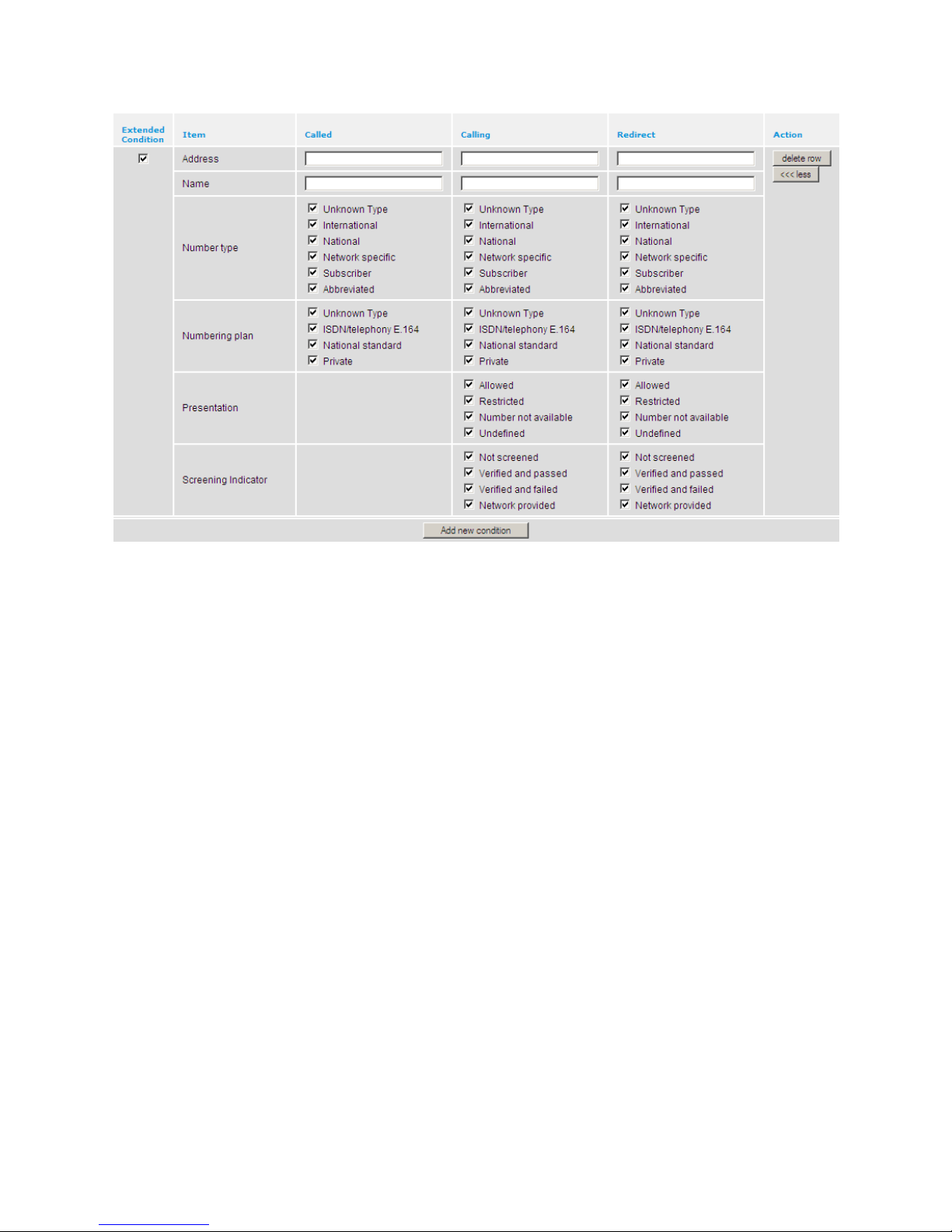
Dialogic 4000 Media Gateway Series SU4.1 Reference Guide
Extended
Condition
Determines whether additional route conditions appear when you click the
more >>> button in the Action column. This parameter is enabled by default.
If Extended Condition is not enabled, a route can only be matched if the
three condition parts (called number, calling number, and redirect number)
match their call address counterpart in any of the lines. Empty Called, Calling,
and Redirect condition entries always match, i.e., a line with the three
condition parts left empty will always apply, thus working as a default route.
If Extended Condition is enabled, a route can only be matched if the three
condition parts (called number, calling number, and redirect number) match
their call address counterpart in any of the lines, and if the route matches at
least one of the enabled conditions in each category. For example, suppose the
Called condition is set to ^123 and the National and Network specific extended
conditions are enabled for the called number. A called number that starts with
123 and is a national number will match, but a called number that starts with
123 and that is not a national or network-specific number will not match.
50
Page 59

Dialogic® Diva® SIPcontrol™ Configuration
Empty Called, Calling, and Redirect condition entries work like this when there
are extended conditions:
If the Called and Calling fields are empty and there are no extended
conditions enabled for those fields, then the called and calling numbers
will always match the route conditions.
If the Called and Calling fields are empty and there are extended
conditions enabled for those fields, then the called and calling numbers
will match the route conditions if they match at least one of the
extended conditions.
If the Redirect field is empty, then the redirect number will always
match the redirect route condition, whether or not there are extended
conditions enabled for the Redirect field.
Address
Called:
If the route is supposed to be valid only for specific called numbers, enter the
regular expression to which the route should apply. A regular expression is a
pattern that can include numbers, alphabetic characters, special characters,
and wildcards.
Diva SIPcontrol attempts to match the regular expression entered here to the
called number transmitted on call setup by the remote device. If there is a
match, Diva SIPcontrol selects the associated route. If there is no match, Diva
SIPcontrol repeats this process with the next route until it finds a match.
Address
Calling:
If the route is supposed to be valid only for specific calling numbers, enter the
regular expression to which the route should apply. A regular expression is a
pattern that can include numbers, alphabetic characters, special characters,
and wildcards.
Diva SIPcontrol attempts to match the regular expression entered here to the
calling number transmitted on call setup by the remote device. If there is a
match, Diva SIPcontrol selects the associated route. If there is no match, Diva
SIPcontrol repeats this process with the next route until it finds a match.
Address
Redirect:
If the route is supposed to be valid only for specific redirect numbers, enter the
regular expression to which the route should apply. A regular expression is a
pattern that can include numbers, alphabetic characters, special characters,
and wildcards.
Diva SIPcontrol attempts to match the regular expression entered here to the
redirect number transmitted on call setup by the remote device. If there is a
match, Diva SIPcontrol selects the associated route. If there is no match, Diva
SIPcontrol repeats this process with the next route until it finds a match.
The following additional parameters appear when Extended Condition is enabled:
Name Called
If the route is supposed to be valid only for specific called numbers, enter a
name for the called numbers to which the route should apply.
Name Calling
If the route is supposed to be valid only for specific calling numbers, enter a
name for the calling numbers to which the route should apply.
51
Page 60

Dialogic 4000 Media Gateway Series SU4.1 Reference Guide
Name
Redirect
If the route is supposed to be valid only for specific redirect numbers, enter a
name for the redirect numbers to which the route should apply.
The following additional parameters appear when Extended Condition is enabled and you click
the more >>> button:
Number type
The calling, called, and/or redirect numbers to which the route should apply
must match one of the enabled number type conditions.
For example, if National and Network specific are enabled in the Calling
column, then the calling number in the route must be either a national or
network-specific number type.
Numbering
plan
The calling, called, and/or redirect numbers to which the route should apply
must match one of the enabled numbering plan conditions. For example, if
ISDN/telephony E.164 and National standard are enabled in the Called column,
then the called number in the route must use either an ISDN/telephony E.164
or national standard numbering plan.
Presentation
The calling and/or redirect numbers to which the route should apply must
match the enabled presentation conditions.
Screening
indicator
The calling and/or redirect numbers to which the route should apply must
match the enabled screening indicator conditions.
Note: If expressions should match from the beginning, prepend the caret symbol ("^") at
the beginning of the expression, for example:
Number: 1234567
Expression: ^123
Format: 4567
Result: 45674567
The address modified by an address map in a routing condition is usually formatted as it
was on arrival. If the address originated from a SIP peer, there will be a host/domain name
attached to the address.
Address Manipulation
You can configure the following parameter in the Address Manipulation section when you
create or modify a route:
52
Page 61
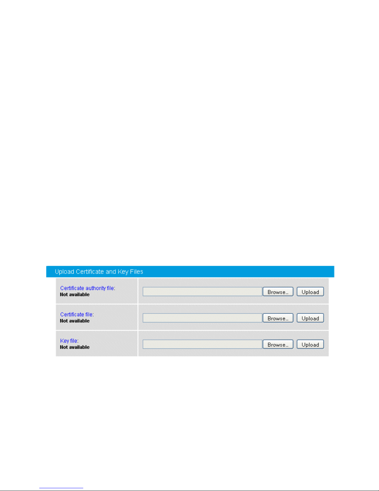
Dialogic® Diva® SIPcontrol™ Configuration
Address Map:
If a route matches, the address manipulation setting allows you to
modify the call addresses according to your needs. For example, if calls
with the called party number starting with "9" should be directed to a
specific peer, it might be desirable to remove this digit. This can be
done with a configured address map. You need to configure the address
map as described under Address Maps before you can select it here.
Security Profiles
For authentication and data encryption, certificates need to be installed on the computer on
which Diva SIPcontrol is installed and on remote computers. For detailed information on
using, generating, and installing certificates, see the following topics in the Data Security
section:
Using Certificates for Authentication and Data Encryption
Generating Private Key Files and Certificates
Uploading the Certificate Authority, Certificate, and Key Files to Dialogic® Diva®
SIPcontrol
Example of Creating a Private Key File and Certificate Request
Uploading a Certificate or Key File
To set up or modify a security profile, click the Details button in the Security Profiles
section. To open the online help for a specific parameter, click the parameter, and a window
with the help text will appear.
The screen below shows the web interface with no certificates uploaded.
To upload a certificate or key file:
1. Click the Browse button next to the type of file you want to upload.
2. In the Choose File to Upload window locate the certificate or key file, and click
Open.
53
Page 62
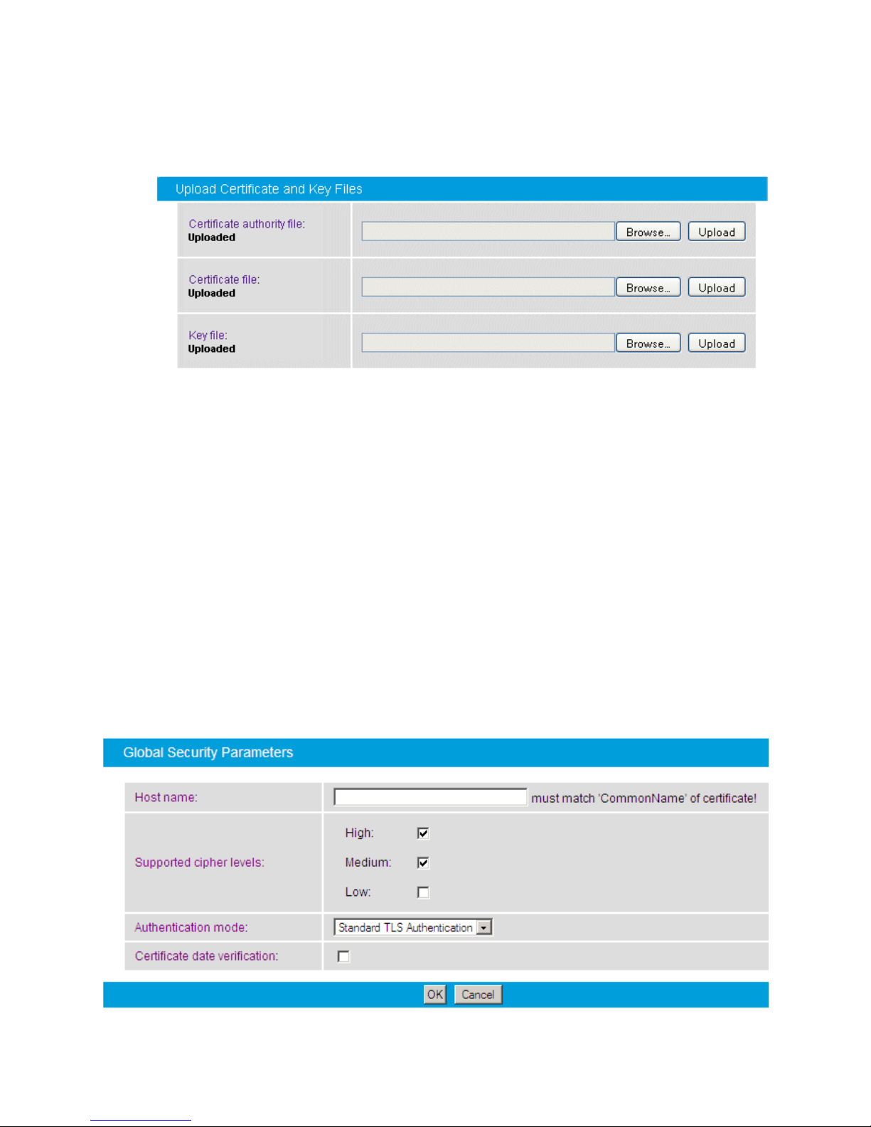
Dialogic 4000 Media Gateway Series SU4.1 Reference Guide
Certificate
authority file:
This file is the root certificate, which is used to sign a
certificate. It is only needed for MTLS or TLS
authentication.
With this file, the CA ensures that the public key contained
in the certificate belongs to the server stated in the
certificate.
Certificate file:
This file is also generated from the CA, and it contains the
public key of the server on which Diva SIPcontrol is
installed. This file is used for encrypting information.
Key file:
This file contains the private key for each endpoint, and it
is used for decrypting information. The key file must not be
password protected.
3. In the Diva SIPcontrol web interface, click Upload. After the certificates are
uploaded, the information below the certification files changes from "Not available"
to "Uploaded". You will not see the paths to the directory in which the files are
stored:
Global Security Parameters
You can configure the following parameters in the Global Security Parameters section
when you set up a security profile:
54
Page 63

Dialogic® Diva® SIPcontrol™ Configuration
Host name
The common name used in the certificate to identify the Diva
SIPcontrol host machine.
Supported cipher
levels:
Cipher is an algorithm for encrypting and decrypting data.
During the SSL handshake between client and server, the
cipher level is negotiated. A low cipher level should only be
used for systems that do not transmit any important
information.
High: This currently means cipher suites with key
lengths larger than 128 bits, and some with 128-bit
keys.
Medium: This currently means cipher suites using 128-
bit encryption.
Low: This currently means cipher suites using 64- or
56-bit encryption algorithms but excluding export cipher
suites.
Authentication
mode:
Select how the server-client authentication should be handled:
Mutual Authentication: MTLS is used by
Microsoft® Office Communications Server 2007 Server
roles and by Microsoft® Exchange 2007 UM role to
communicate with each other. In this mode, both peers
need to authenticate each other and both client and
server exchange certificates.
For connecting to Microsoft® Office Communications
Server 2007 R2 Mediation Server via TLS, use Standard
TLS authentication mode. For connecting to
Microsoft® Lync Server or Exchange 2007 UM role via
TLS, use MTLS authentication mode.
Standard TLS Authentication: This is the normal
authentication mode, in which the client asks the server
for authentication to ensure a secure connection to the
correct server.
No Authentication: In this mode, neither the server
nor the client needs to prove its authentication.
The default setting is Standard TLS Authentication.
Certificate date
verification:
If enabled, the expiration date of the peer certificate is verified.
If the certificate is expired, an informational message is
displayed and the call is aborted.
55
Page 64

Dialogic 4000 Media Gateway Series SU4.1 Reference Guide
LDAP
The Lightweight Directory Access Protocol (LDAP), is an application protocol that programs
use for querying information from a server. The protocol runs over TCP/IP. Deployments
today tend to use Domain Name System (DNS) names for structuring the topmost levels of
the hierarchy. LDAP servers index all the data in their entries, and "filters" can be used to
select the person or group for which you are looking. LDAP is appropriate for any kind of
directory-like information, where fast lookups and less-frequent updates are the norm. For
example, when you use Microsoft® Outlook and search the address book for a colleague,
you access the Microsoft
How to Use LDAP to Access Active Directory for Routing Calls via
Diva SIPcontrol
You can enable LDAP functionality via Diva SIPcontrol web configuration. When LDAP is
activated, Diva SIPcontrol will query the server on startup and store the query results
internally for a faster lookup. In a default configuration, this internal storage will be updated
once a day to reflect changes on the LDAP database. If you use LDAP, you need to configure
two routes for one LDAP call:
One route should contain the LDAP destination.
The other route should contain the final destination.
®
Active Directory database via LDAP.
The order of the routes is irrelevant, but it is important to configure the first route with the
conditions needed to avoid recursion.
Use Case for LDAP
In this scenario, the gateway is connected between the PSTN or PBX and a VoIP endpoint.
Additionally, the gateway receives a call from the TDM network that is intended for the VoIP
endpoint. However, the VoIP endpoint does not respond to the original INVITE request or it
responds with a failure. The gateway must query the Active Directory server to determine if
there is an alternate address (i.e. phone number, etc.) where the VoIP endpoint can be
contacted, and if so, the gateway must route the call to the alternate address.
56
Page 65
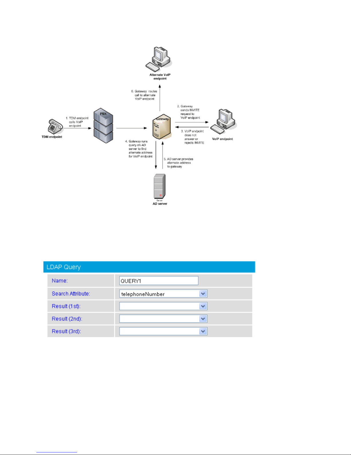
Dialogic® Diva® SIPcontrol™ Configuration
To add LDAP query settings, click the Add button in the LDAP section. To change the
settings for each LDAP, click the Details button on the right hand side.
LDAP Query
You can configure the following parameters in the LDAP Query section when you create or
modify an LDAP:
57
Page 66
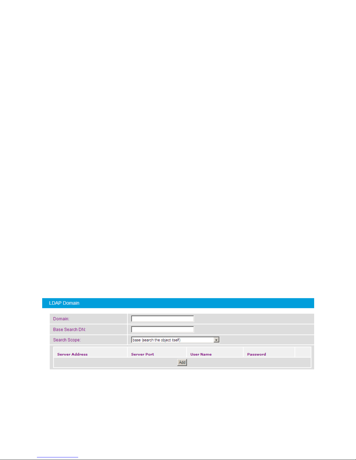
Dialogic 4000 Media Gateway Series SU4.1 Reference Guide
Name
Enter a name to easily identify the LDAP query.
Search attribute:
Select the attribute to search for:
telephoneNumber: The primary office number.
homePhone: The primary home/private number.
mobile: The primary mobile number.
facsimileTelephoneNumber: The primary fax number.
proxyAddresses: E-mail address attributes that can have
either format SMTP:[email protected] or
sip:[email protected].
The following attributes are used by Office Communications
Server 2007, Office Communications Server 2007 R2, and Lync
Server 2010:
msRTCSIP-PrimaryUserAddress: This attribute
contains the SIP address of a given user.
msRTCSIP-Line: Refers to a user's primary office
number as specified in the Active Directory msRTCSIP-line
attribute, which the Microsoft® Office Communications
Server uses to perform reverse number lookup to obtain
all the user's SIP endpoints.
Result:
The list defines the attributes for which to search. The called
address searched for will be replaced by the contents of the result
attribute with the highest priority value. if there is more than one
attribute with that priority, the call will be forked and several
simultaneous call attempts will be made. The attributes in result
2 and 3 are sequentially searched only if the address with the
highest priority fails.
LDAP Domain
58
Page 67

Dialogic® Diva® SIPcontrol™ Configuration
Domain:
Enter the domain name of the LDAP server, e.g., dialogic.com.
Base Search DN:
This is the starting point in the Active Directory hierarchy at
which your search will begin, e.g.,
ou=EMEA,ou=corp,dc=dialogic,dc=com.
Search Scope:
The LDAP search scope indicates the set of entries at or below
the base search DN that can be considered potential matches for
a search operation.
There are three search scope values:
base (search the object itself): This specifies that the
search should only be performed against the entry
specified as the base search DN. No entries below it will be
considered. Use this option if the base search DN is close
to the data to be searched for, because this way desired
data can be found quickly.
one level (search the object’s immediate children):
This specifies that the search operation should only be
performed against entries that are immediate
subordinates of the entry specified as the base search DN.
Neither the base entry itself nor the entries below the
immediate subordinates of the search base entry are
included.
subtree (search the object and all its decendants):
This specifies that the search operation should be
performed against the base search DN itself and all of its
subordinates.
Server Address:
Enter the IP address of the Active Directory server. This entry is
mandatory, because Diva SIPcontrol does not use a default
server.
You can enter the server address either as an IP address or as an
FQDN, e.g., 11.11.11.11 or ldap.dialogic.com.
It is possible to configure multiple servers for an LDAP query. In
this case, SIPcontrol will use the second server if the first one
fails.
Server Port:
Enter the port to which the server is listening. The default value
is 389.
and LDAPS 636. If you set the port to 0, Diva SIPcontrol will
select a port automatically.
If you use an indexed database, such as Microsoft® Active
Directory, set the port to 3268 to speed up LDAP queries.
You can configure the following parameters in the LDAP Domain section when you define
or modify an LDAP:
59
Page 68
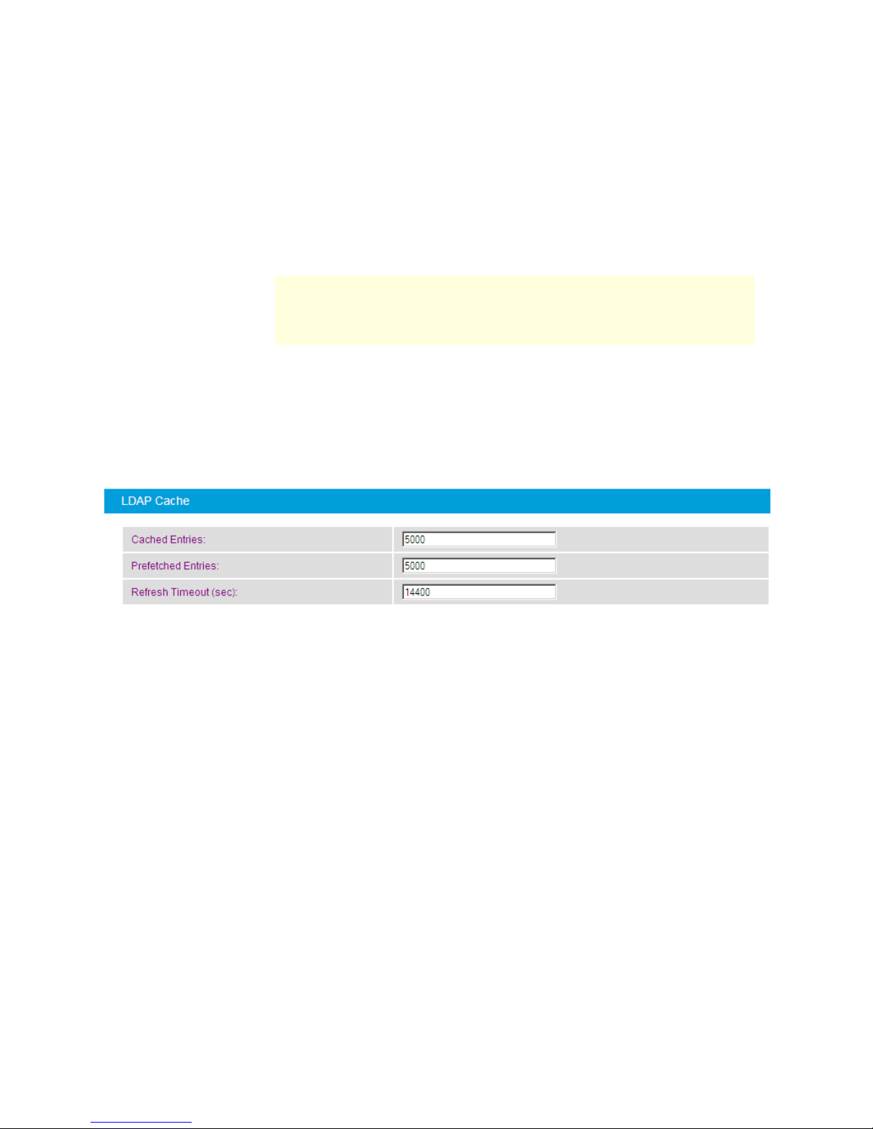
Dialogic 4000 Media Gateway Series SU4.1 Reference Guide
User Name:
Enter a user name. This can be a DN, UPN (User Principal Name,
e.g., [email protected]), Windows NT style username (e.g.,
domain\username), or another name that the directory server
will accept as an identifier.
In some cases, it is possible to connect to an LDAP server without
a user name and password. If it is not possible, you can create a
dummy user for this gateway task.
Password:
Enter a password for the user account.
Note: Diva SIPcontrol currently supports Simple authentication,
which means that the password is transmitted in clear text over
the network. The password also is stored and processed locally in
clear text.
It is recommended that you use a separate user account with
restricted permissions for Diva SIPcontrol access.
Cached Entries
Number of local cache entries resident in the system memory.
Valid range is from 100 to 1000000.
Default is 5000 entries.
Prefetched Entries
Number of LDAP entries loaded into the local LDAP cache during
startup. Valid range is from 0 (disabled) to the number of Cached
Entries.
Default is 5000 entries.
Refresh Timeout
(sec)
Amount of time allowed to elapse from the time an LDAP entry is
cached to the time the cached entry will no longer be used. If a
cached entry is queried after the refresh timeout elapses, the
entry will be retrieved from the LDAP server and cached again. If
the LDAP server is not reachable during a query, the older
cached value remains in the cache and will be used for the
query.
Valid range is from 0 to 2^32 -1 seconds (limited by a 32 bit
variable).
Default is 14400 seconds (4 hours)
LDAP Cache
You can configure the following parameters in the LDAP Cache section when you define or
modify an LDAP:
60
Page 69

Dialogic® Diva® SIPcontrol™ Configuration
Dialplans
With help of the local phone settings, Diva SIPcontrol is able to convert a received call
address to a normalized form, e.g., the E.164 format. This not only eases the definition of
subsequent conditions or maps, but it also converts the call to the format required by the
receiver.
The dialplan module supports the following features:
Number expansion and reduction: called, calling, and redirected numbers are
converted to one of the following formats: international, national, local, or internal
(extension-only) format. For each format, either prefix digits or digital number type
flags can be used.
Adding and removing the line access code: If not present, dialed numbers are
automatically prepended by the digits needed to access the public telephone
network.
Support for the North American numbering plan: Up to 10 area codes can be
configured to be treated differently. For example, in many areas, dialing into
neighboring areas does not require dialing a long-distance prefix.
For more information about how dialplans work, see Number Normalization Based on a
Dialplan.
Important information about the outside access digit configuration
Configure the outside access digit only if there is a PBX between the PSTN and Diva
SIPcontrol, and if this PBX requires the outside access digit for external calls. If you need to
configure the outside access digit, also configure the following related options:
Incoming PSTN access code provided by the PBX: This option defines whether
Diva SIPcontrol expects the outside access digit in the calling number of external
calls from the PBX. The PBX normally prepends the outside access digit to the calling
number of incoming external calls in order to enable callback functionality at internal
phones. If this is the case, enable this option.
PSTN access code provided by the caller: This option defines whether Diva
SIPcontrol expects the outside access digit in the called number of external calls. It
is normally required to prepend the outside access digit to call an external number
from an internal phone. However, in some configurations this is not required, such as
a configuration that is part of the North American numbering plan (NANP), where an
internal number can be identified based on its length.
Enable this option if the internal users that use SIPcontrol for external calls prepend
the outside access digits in their calls; otherwise disable it.
Note: Diva SIPcontrol's number normalization function does not remove outside
access digits as a PBX can do for external calls. If Diva SIPcontrol needs to behave
like a PBX with an outside access digit for external calls, use the Address Map
functionality in combination with a Routing module.
To add a dialplan, click the Add button. To change the configuration settings, click the
Details button on the right hand side. To open the online help for a specific parameter, click
the parameter, and a window with the help text will appear.
You can configure the following parameters in the General section when you create or
modify a dialplan:
61
Page 70
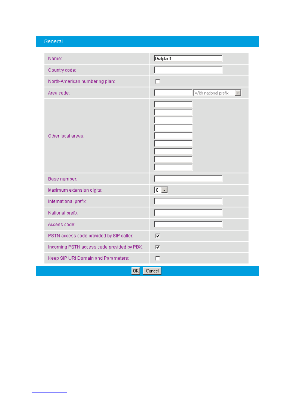
Dialogic 4000 Media Gateway Series SU4.1 Reference Guide
Name:
Enter a name to easily identify the dialplan, e.g., Stuttgart office.
Country code:
Enter the country code without any prefixes for the country in which
the computer with the installed Diva SIPcontrol is located, e.g. 1 for
US or 49 for Germany.
62
Page 71

Dialogic® Diva® SIPcontrol™ Configuration
North-American
numbering plan:
Select this option if the North American numbering plan (NANP) is
needed for your configuration. With the NANP, a city can have more
than one area code, consequently it is not evident how to dial a
number in the same city. Diva SIPcontrol allows you to enter various
area codes that are considered local and should be called without
long-distance prefix. See Area code and Other local areas for
more information.
Area code:
If you do not use the North American numbering plan (NANP), enter
the area code without the leading zero here. If the NANP is needed
for your configuration, enter the code for the home area here and
enter the codes for the other local areas in Other local areas.
If you need to use the NANP, you can choose between the following
number transmission methods:
With national prefix: The long-distance code is added to the
number.
Local: The number is transmitted without any area code.
Without national prefix: The number is transmitted without the
long-distance prefix.
Other local
areas:
You can enter various area codes that are considered local and
should be called without the long-distance prefix. This is the case in
some countries where the North American numbering plan is
deployed, e.g., in the USA. With the NANP, a city can have more
than one area code; consequently, it is not clear how to dial a
number in the same city.
Base number:
Enter your subscriber or trunk number without a country and area
code. If you use MSNs, leave this field empty and enter the length of
the MSNs in Maximum extension digits.
Maximum
extension digits:
Specify the maximum number of extension digits. Use the "arrow
up" and "arrow down" buttons to do so.
International
prefix:
Enter the international prefix for your country, e.g., 00.
National prefix:
Enter the digits of the national prefix, e.g., 0 in Germany.
Access code:
Enter the digits that are needed to get access to the public network,
e.g., 9.
PSTN access
code provided
by SIP caller:
Select this option if the SIP caller has to provide the access code. If
the length of the called number is not sufficient to identify it as an
internal number, activate this option to avoid ambiguous numbers.
This is usually the case if you are not using the North American
Numbering Plan (NANP).
63
Page 72
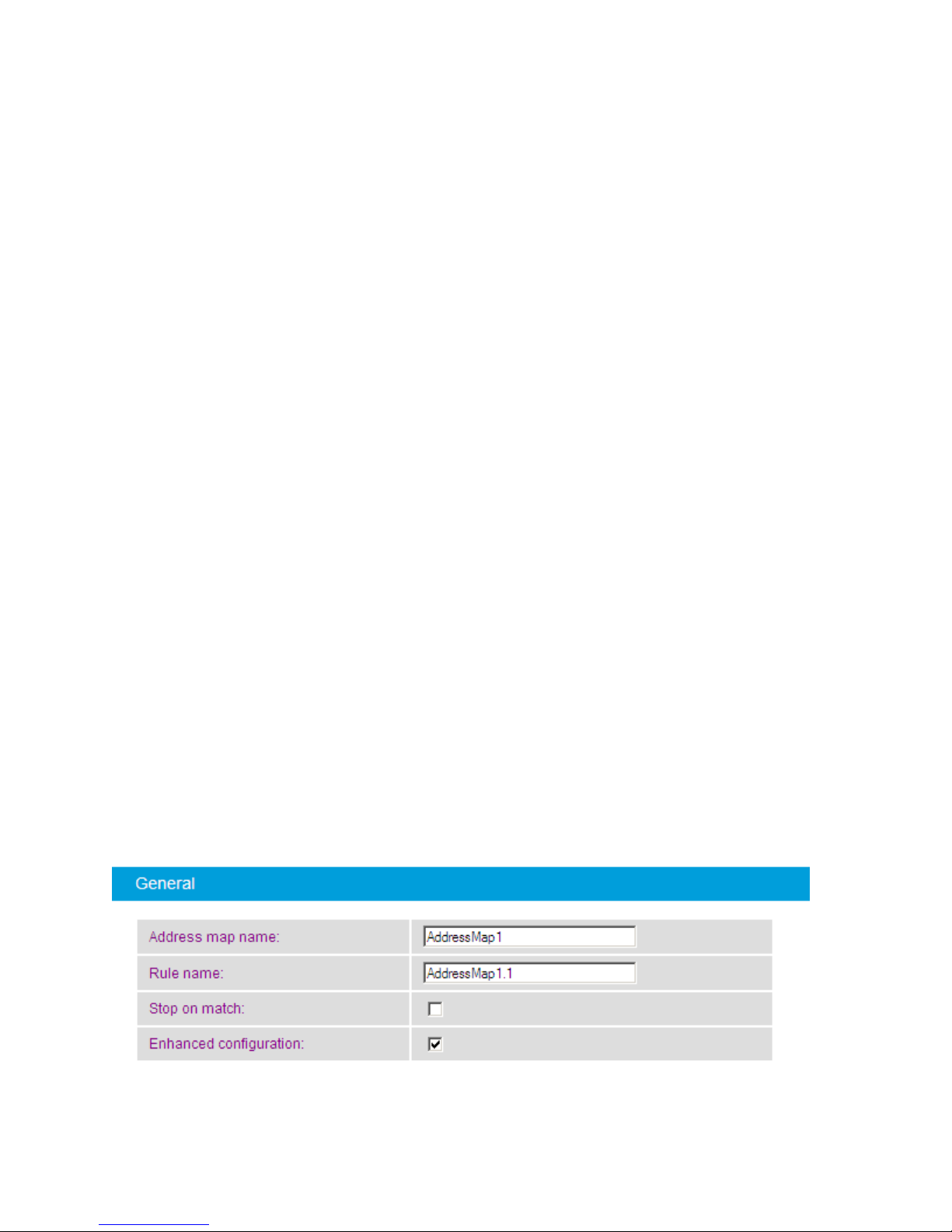
Dialogic 4000 Media Gateway Series SU4.1 Reference Guide
Incoming PSTN
access code
provided by
PBX:
Select this option if the PBX adds the access code to the calling
number for incoming external calls.
Keep SIP URI
Domain and
Parameters:
(Relevant for calls from SIP only)
If this option is enabled, then the SIP URI domain and parameters
are kept as a suffix of the resulting, normalized address. This may
have an impact on the address maps and conditions applied after
normalization. In the case of a SIP-to-SIP call, the host part of the
SIP URI is forwarded to the other SIP peer.
If this option is disabled (the default), then the number
normalization process removes the SIP URI domain and parameters
from the resulting address, leaving only the SIP user part in the
resulting address.
Address Maps
In general, address maps should be used for cases that are not covered by the dialplan.
Possible scenarios are:
Set the calling number to that of the central office on SIP to PSTN calls,
Change the called extension to another value if an employee left.
Remove trunk prefixes while routing to a global voicemail server.
Each address map consists of a number of rules that are checked and applied from first to
last until a matching rule is found that has the Stop on match option enabled. A rule
matches only if all conditions of that rule match. The order of the address maps is not
important, but the order of the rules within a map is significant and can be changed with the
"arrow down" and "arrow up" buttons in Microsoft® Internet Explorer® or the Up and
Down buttons in Mozilla Firefox.
To add an address mapping, click the Add button. To change the settings for each address
mapping, click the Details button on the right hand side. To open the online help for a
specific parameter, click the parameter, and a window with the help will appear.
You can configure the following parameters when you create or modify an address map:
64
Page 73

Dialogic® Diva® SIPcontrol™ Configuration
Address map
name:
Enter a name for the address map that helps you remember the
purpose of the map. This name is shown in other menus where an
address map can be selected.
Note: The name can be edited only during the creation of an
address map.
Rule name:
Enter a name for the rule of the map, e.g., "Remove 9 from all
incoming calls".
Stop on match:
This flag determines whether Diva SIPcontrol should continue to
search for matching rules when all expressions match all addresses
of a call. If set, the address matching is aborted when there is a
match.
Enhanced
configuration
This flag determines whether Diva SIPcontrol uses the new
interface for configuring address maps. The new interface handles
the flag and number portions of a SIP address separately. For
example, with the SIP address [email protected],
the flag portion is + and the number portion is 17166391234.
In addition, the new interface supports the ability to specify the
number type, numbering plan, and presentation indicator directly,
while the older version supported prefixing the address with "+,"
"N", and "S", respectively, to specify a limited subset of number
types.
Leave this option enabled (the default), unless you need to use the
old interface for compatibility reasons. (For example, if you need
to import address maps from an earlier SIPcontrol version.) For
address maps created in earlier versions of SIPcontrol, this option
is disabled by default.
Note: In the old interface, number type flags from digital
networks, e.g., ISDN or SS7, are converted into special prefixes on
the SIP side. Therefore, the following address formats apply only
to the old interface:
+ indicates an international number type, if it is the first
character in the string
N indicates a national number type, if it is the first
character in the string
S indicates a subscriber number type, if it is the first
character in the string
The following fields appear when the Enhanced configuration option is enabled:
65
Page 74
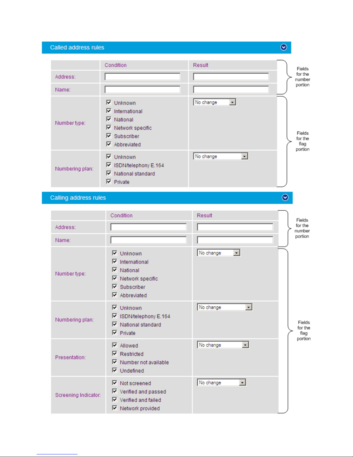
Dialogic 4000 Media Gateway Series SU4.1 Reference Guide
66
Page 75
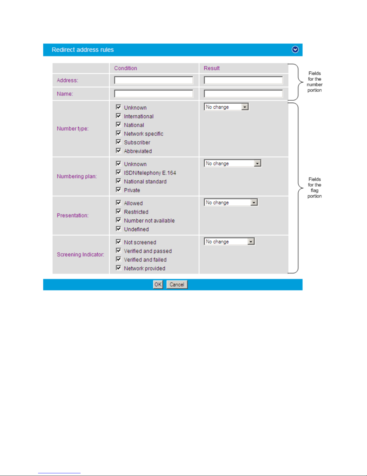
Dialogic® Diva® SIPcontrol™ Configuration
Address
Checks or manipulates the current address (normally a number for
a PSTN address or a SIP-URI for a SIP address). To remove the
part matched by the condition, set the Result field to empty. To
check for a specific condition and keep the original address, set
the Result field to $&.
Name
Checks or manipulates the current name. To remove the part
matched by the condition, set the Result field to empty. To check
for a specific condition and keep the original address, set the
Result field to $&.
Number type
Checks or manipulates the number type of the current address.
For unmodified SIP addresses, the number type is "unknown". To
check for a number type without changing it, set the Result field to
No change.
67
Page 76

Dialogic 4000 Media Gateway Series SU4.1 Reference Guide
Numbering plan
Checks or manipulates the numbering plan of the current address.
For unmodified SIP addresses, the numbering plan is Unknown.
To check for a numbering plan without changing it, set the Result
field to No change.
Presentation
Checks or manipulates the presentation indicator. For unmodified
SIP addresses, the presentation is Undefined. To check for a
presentation without changing it, set the Result field to No
change.
Screening
indicator
Checks or manipulates the screening indicator. For unmodified SIP
addresses, the value is Not screened. To check for a screening
indicator value without changing it, set the Result field to No
change.
Note: If expressions should match from the beginning, prepend the caret symbol ("^") at
the beginning of the expression, for example:
Number: 1234567
Expression: ^123
Format: 4567
Result: 45674567
The address modified by an address map is usually formatted as it was on arrival. If the
address originated from a SIP peer, there will be a host/domain name attached to the
address.
Cause Code Maps
Depending on the type of SIP peer selected, different default mapping tables are used to
adapt SIPcontrol's responses to the values expected by that peer.
If the internal default mapping table provided by Diva SIPcontrol does not fulfill your needs,
e.g., because your local PBX uses non-standard cause codes, you can configure your own
cause code mapping table, which will be checked before the default table is checked. See
Cause Code Mapping for the cause/response code mapping table. If you create your own
cause code mapping table, make sure to select it in the SIP Peers section under Enhanced.
To add a cause code, open the Cause Code Maps section and click the Add button. To
change the settings, click the Details button on the right hand side. To open the online help
for a specific parameter, click the parameter, and a window with the help text will appear.
You can configure the following parameters when you create or modify a cause code:
68
Page 77
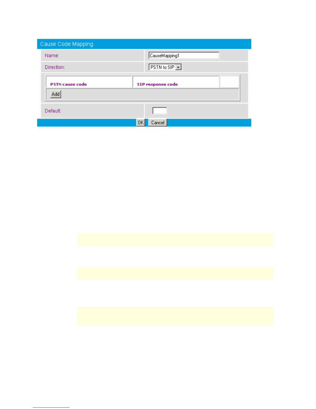
Dialogic® Diva® SIPcontrol™ Configuration
Name
Enter a name to easily identify the cause code mapping table.
Direction
Select the direction for which this table is used:
Select PSTN to SIP to configure mappings of PSTN cause codes to
SIP response codes. This mapping is used if a call from a SIP
endpoint to a PSTN endpoint cannot be completed.
Select SIP to PSTN to configure mappings of SIP response codes
to PSTN cause codes. This mapping is used if a call from a PSTN
endpoint to a SIP endpoint cannot be completed.
PSTN cause
code
Enter the PSTN cause code equivalent to the SIP response code entered in
this menu. The PSTN cause code is also known as Q.850 cause code. Valid
values are 1 to 127.
Note: For SIP to SIP calls or PSTN to PSTN calls, the original cause code
is preserved, so mapping is unnecessary.
SIP
response
code
Enter the SIP response code equivalent to the PSTN cause code entered in
this menu. The values are only valid in the range from 400 to 699.
Note: For SIP to SIP calls or PSTN to PSTN calls, the original cause code
is preserved, so mapping is unnecessary.
Default
Enter the cause or response code that Diva SIPcontrol should use per
default if no mapping for the received cause or response code is specified
in this table.
Note: If this value is not configured and no mapping for the received
cause or response code is specified in this table, Diva SIPcontrol's internal
default mapping table will be used.
69
Page 78
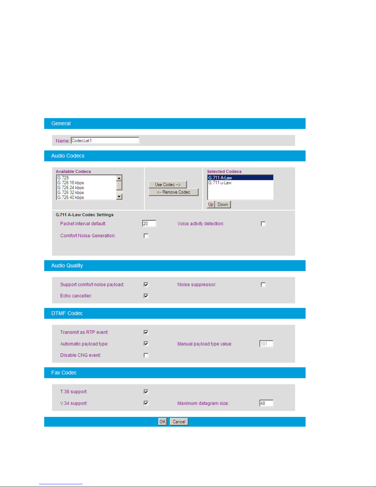
Dialogic 4000 Media Gateway Series SU4.1 Reference Guide
Codec Profiles
To configure a codec profile, click the Add button. To change the settings, click the
Details button on the right hand side. If you create a codec profile, make sure to select it in
the SIP Peers section, under Enhanced. To open the online help for a specific parameter,
click the parameter, and a window with the help text will appear.
You can configure the following parameters when you create or modify a codec profile:
70
Page 79

Dialogic® Diva® SIPcontrol™ Configuration
Name:
Enter a name to easily identify the codec profile You can select the codec
profile in the SIP Peers section.
Available
Codecs:
This list includes all available codecs. If you want to use a certain codec,
select it and click Use Codec. The codec will be moved to the Selected
Codecs list. The G.729 codec can only be used after you have purchased
and activated a license. See License Activation for more information.
Selected
Codecs:
By default, the G.711 A-law and G.711 µ-law codecs are selected. If you
want to delete a certain codec, select it and click Remove Codec. The
codecs are used according to their position in the list, with the first codec
being the first to be used. To change the order, use the Up and
Down buttons.
Packet
interval
default:
Interval between RTP packets in an RTP stream. Also known as
packetization time or RTP frame size.
Voice
activity
detection:
If you activate voice activity detection, silence during a conversation is
detected, and the data rate is reduced.
Comfort
Noise
Generation:
If you enable this parameter, packets with low artificial background noise
are sent to fill periods where no data packets are received from the SIP
peer. This helps prevent the other party from thinking the transmission
has been lost (because of the silence) and hanging up prematurely.
Note: Support for this feature depends on the type of Diva Media Board
present in the system. If the hardware does not support this feature, the
setting is ignored.
Support
comfort
noise
payload:
If you enable this parameter and VAD is configured for the codec used for
the call, periods of silence will be replaced by sending a special "comfort
noise" signal to the SIP peer. This allows a supporting SIP device to
generate appropriate artificial background noise in order to remove the
impression of the call being interrupted.
If the SIP peer does not support this type of event, this setting has no
effect.
Noise
suppressor:
Enable this parameter if you want to use the noise suppressor
functionality.
Echo
canceller:
If you enable this parameter, the audio echo canceller is active for calls to
or from the PSTN.
Transmit as
RTP event:
This option enables DTMF and fax tones to be sent and received as RTP
events instead of audio signals.
Automatic
payload
type:
G.726, iLBC, RT Audio, and DTMF have a dynamic RTP payload. If you
enable this option, Diva SIPcontrol sets the values automatically. If the
endpoint cannot handle the automatically set value, enter it manually
under Manual payload type value.
71
Page 80

Dialogic 4000 Media Gateway Series SU4.1 Reference Guide
Manual
payload
type value:
Some endpoints expect a certain payload type value. You can enter any
value between 96 and 127. In calls from SIP to the PSTN, Diva SIPcontrol
uses the value suggested by the endpoint. Generally, this parameter is
left at its default value.
Disable
CNG event:
Select this option to transmit the CNG event as an in-band audio signal
instead of an RTP event according to RFC 4733.
Note: This option is only available if the option Transmit as RTP event
is enabled.
T.38
Support:
T.38 is a protocol that enables fax transmissions on the IP network in real
time. Enable this option if T.38 fax should be supported. Note that this
feature is supported on Diva Media Boards with multiple ports only after
activating the respective license. See License Activation for more
information.
V.34
Support:
The V.34 fax transmission protocol allows facsimiles to be transmitted at
a maximum speed of 33.600 bps. Enable this option if V.34 should be
supported. Note that this feature is supported on Diva Media Boards with
multiple ports only after activating the respective license. See License
Activation for more information.
Maximum
datagram
size:
This value defines the maximum amount of data that can be transmitted
in one T.38 packet. Some endpoints are limited to packets of a certain
size. You can enter a value between 32 and 192. Default is 48 bytes.
Registrations
SIP devices can communicate directly if the URL of both devices is known, but in general,
SIP gateways are used in a network to enable functionalities such as routing, registration,
authentication, and authorization.
Registration at a registrar server can be useful because in many cases, only the SIP address
of a user is known but the location (SIP address of the device) is unknown or can change. A
registrar server keeps track of the location of user agents from which the registrar server
has received REGISTER requests. Thus, only the SIP address of the user needs to be sent to
the registrar server, which then returns one or more contact addresses for the user.
If Diva SIPcontrol is configured to use a registrar server, it registers with the server as soon
as it is active. Thus, all local addresses configured for registration are registered with the
server. You can use either a private registrar service or a public registrar server.
To configure a registrar server, open the Registrations section and click the Add button.
To change the settings, click the Details button on the right hand side. To open the online
help for a specific parameter, click the parameter, and a window with the help text will
appear.
You can configure the following parameters when you create or modify a registration:
72
Page 81
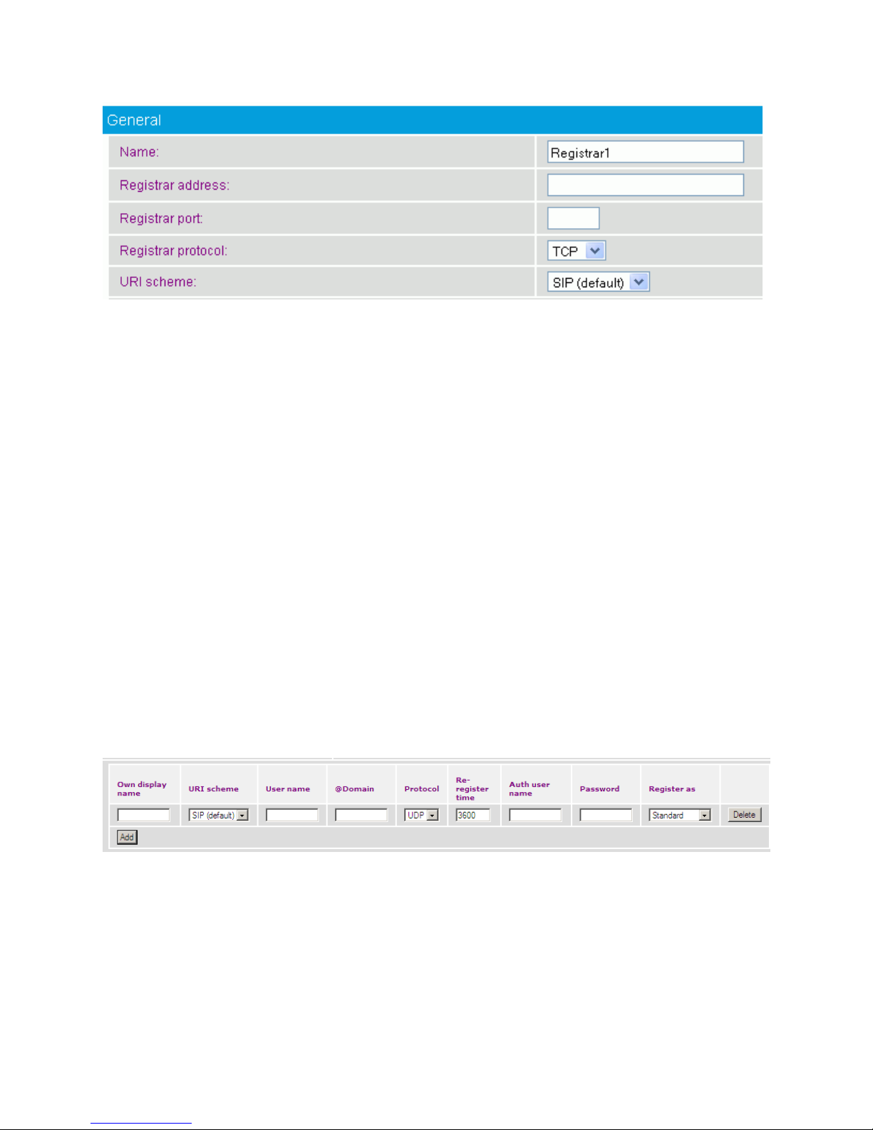
Dialogic® Diva® SIPcontrol™ Configuration
Name:
Enter a name for the registrar configuration.
Registrar
address:
Enter the IP address or the hostname of the registrar server.
Registrar
port:
Enter the port number of the registrar server. Usually, the registrar
server is listening on port 5060.
Registrar
protocol:
Select the protocol the registrar server uses.
URI scheme:
This option is only available if you selected TLS as Registrar
protocol.
Calls are transmitted via various proxy servers. Some of them do not
transmit the calls as encrypted calls. If you select SIP (default), you
allow calls to be transmitted via such proxy servers.
To make sure that a call is sent encrypted to the proxy of the remote
side, select SIPS (secure SIP). If a call is routed via a proxy server
that is not able to route the call encrypted, it rejects the call and the
call is send to another proxy until it can be transmitted.
Own display
name:
Enter the name that should be displayed at the registrar server.
URI scheme:
Select either SIP (default) or SIPS as URI scheme.
User name:
Enter the name or number that Diva SIPcontrol uses to register at the
registrar server.
To configure the settings for each user that should register at the same registrar server,
click Add and configure the following parameters:
73
Page 82
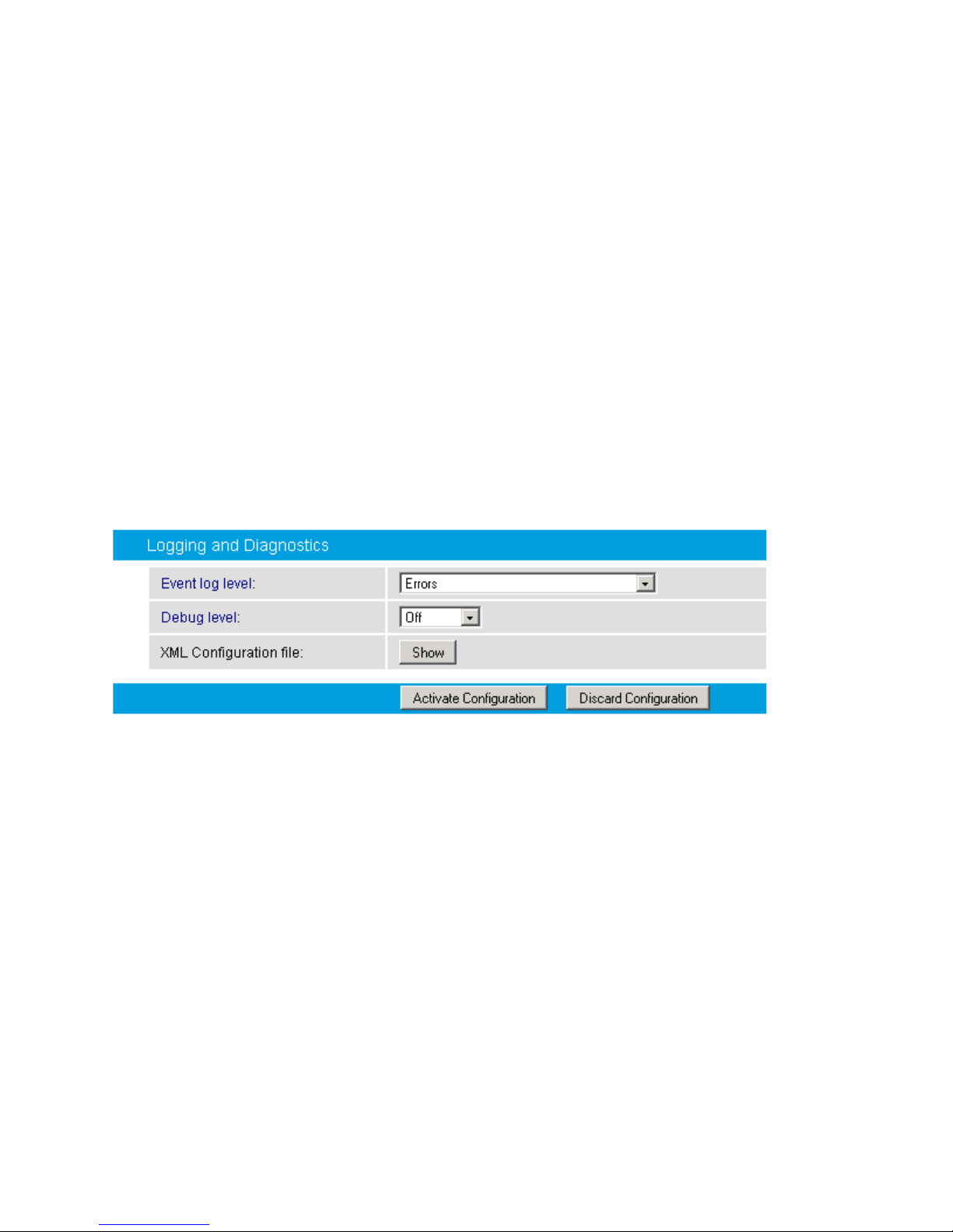
Dialogic 4000 Media Gateway Series SU4.1 Reference Guide
@Domain:
Enter the domain name of the registrar server.
Protocol:
Select UDP if you register as an e-phone gateway.
Re-register
time:
Enter the re-register time in seconds. This is the time for which the
registration to the registrar server remains valid. After this time has
elapsed, the SIP stack service would need to re-register to be available
again. The default value is 3600 seconds.
Auth user
name:
Enter a user name for authentication at the registrar server.
Password:
Enter your password for authentication at the registrar server.
Register as:
Leave the setting at the default value Standard. Select e-phone
GW only if you use e-phone and you want Diva SIPcontrol to function
as a gateway for e-phone.
Event Log
Level:
A computer with Diva SIPcontrol installed can write different types of
events into the System Event Log. The details for each event log are
described in Event Logging.
Debug Level:
The debug level setting can be used for debugging and tracing purposes.
During normal operation, it should be set to Off to lessen the effect on
system performance.
XML
configuration
file:
Shows the configuration in raw format. This option is used only by
Dialogic Support.
Logging and Diagnostics
You can configure the following parameters shown in Logging and Diagnostics section:
74
Page 83

6. Data Security
Data Security Overview
Since version 2.0, Diva SIPcontrol provides the following security options for transmitted
and received data:
Secure HTTP: You can use Secure HTTP (HTTPS) to transmit data between the web-
based configuration interface of Diva SIPcontrol and your web browser.
TLS: The Transport Layer Security (TLS) protocol can be used to encrypt and
authorize SIP messages.
Secure RTP: The Secure Real-time Transport Protocol (SRTP) can be used for
encrypting the data of the actual conversation.
Note: The HTTPS and TLS protocols require digital identity Certificates (e.g., public key
certificates.
This section describes the use of the Secure HTTP, TLS, and Secure RTP protocols. It also
describes how to generate, install, and use private key files and certificates.
Secure HTTP
HTTP is a protocol that transmits data between the web-based configuration interface of
Diva SIPcontrol and your web browser. Even though the HTTP interface has access security
(via a password), the transmitted data is not entirely secure. The data is transmitted as
clear text and thus it is possible for the transmission to be intercepted and, in turn, for the
data to be read.
HTTPS uses HTTP over an encrypted Secure Sockets Layer (SSL) or Transport Layer
Security (TLS) connection and with a different default port than HTTP.
For example, if a message containing a request to change a password was captured by a
third party, the third party could log on to the Diva SIPcontrol web interface and change the
configuration. HTTPS encrypts and authenticates HTTP data, and thus the data is no longer
transmitted as clear text and is not easily readable.
HTTPS requires two actions by the user:
Both Diva SIPcontrol and the computer on which the web browser used to connect to
Diva SIPcontrol via HTTPS is running must be configured with the proper certificate.
When accessing the Diva SIPcontrol web interface, use https://<IP-address-or-URL-
of-Diva-Webserver>:10006/ instead of http://<IP-address-or-URL-of-DivaWebserver>:10005/.
TLS
SIP (Session Initiation Protocol) is a signaling protocol used for VoIP calls over the Internet.
SIP messages contain information such as call-party information, call media type, whether it
is a secure call, and if so, what encryption algorithm is used, etc. SIP can be carried by
UDP, TCP, or TLS transports. Both UDP and TCP transport data in clear text. As a result,
UDP and TCP can easily be monitored by a third party. TLS, on the other hand, carries SIP
data in a secure way by encrypting the data and authenticating the transport connections.
Authentication helps to ensure that you are talking to the intended peer. For authentication
purposes, you need to install Certificates, as described in Security Profiles, and enable TLS
as the transport protocol, as described in Network Interfaces.
75
Page 84

Dialogic 4000 Media Gateway Series SU4.1 Reference Guide
Secure RTP
Once a Voice over IP (VoIP) call is established, voice data is transported in packets with the
Real-time Transport Protocol (RTP). The voice data can be easily extracted from RTP
packets and replayed using commercially available software. SRTP adds security by
encrypting voice data and authenticating packets. Digital identity certificates are not
required, and the parameters are negotiated during call initiation time. SRTP mode is
activated typically in combination with TLS, but in some cases (e.g., testing, intranet
connections only) it is useful to allow SRTP also without TLS being activated.
For encryption and decryption of data, SRTP uses ciphers. The two parties involved in a
conversation must be "compatible" in the sense that each party understands the other
party's cipher requirements and supports them. Diva SIPcontrol supports the following
ciphers: DH, ADH, AES (128-256 bits), 3DES (64 bits), DES (64 bits), RC4 (64bytes), RC4
(256 bytes), MD5, SHA1.
SRTP can be set for each SIP peer in the security configuration. For information, see
Security Profiles. The cipher level can be set in the Global Security Parameters.
Using Certificates for Authentication and Data Encryption
For authentication and data encryption, certificates need to be installed on the computer on
which Diva SIPcontrol is installed and on remote computers. When a secure domain is
opened, server and client authenticate each other with a so called "SSL handshake". With
this handshake, the identity of a user is certified and it is assured that the user can be
trusted. All necessary certificates should be provided by a Certificate Authority (CA), and
they are issued for one domain name. For test purposes or internal usage, you can also
create and sign your own self-signed certificate, e.g., with one of the many tools available
on the internet. Search for "self-signed certificate" and you will find a list of possible tools.
But you need to be aware that self-signed certificates do not provide the same security as
CA-signed certificates. Also, many web browsers check if the certificate is signed by a CA,
and, if it is not, a warning message will appear asking whether the user really wants to trust
that web site, which can make the user feel insecure.
Certificate files can be generated in different formats, e.g., .pem, .der, .cer, or .pfx. All files
need to be in "pem" format (base64 encoded) in order to be used by Diva SIPcontrol.
A default certificate is provided with the software, but for security reasons, you should
install your own web server certificate.
Note for CER files: CER files can be renamed to .pem directly if they are base64 encoded.
No bag attribute lines and/or additional CR and empty lines are allowed. If CER files are
ASN.1 coded, they need to be converted to with a converter tool.
Note for PFX files: The PFX or PKCS#12 format is a binary format for storing the server
certificate, any intermediate certificates, and the private key in one encryptable file. When
converting a PFX file to PEM format, tools like OpenSSL will put all the certificates and the
private key into a single file. You will need to open the file in a text editor and copy each
certificate and private key (including the BEGIN/END statements) to its own individual text
file and save them as certificate.cer, CACert.cer, and privateKey.key respectively.
76
Page 85

Data Security
How to Retrieve Keys and Certificates from a PFX File for Use in Diva
SIPcontrol
In the following procedure openssl is used as example converter tool.
1. Export the private key file from the PFX file:
openssl pkcs12 -in filename.pfx -nocerts -out protected-key.pem
2. Remove the passphrase from the private key as required by Diva SIPcontrol:
openssl rsa -in protected-key.pem -out key.pem
3. Export the certificate file from the PFX file:
openssl pkcs12 -in filename.pfx -clcerts -nokeys -out cert.cer
4. Export the Root CA certificate file from the PFX file:
openssl pkcs12 -in filename.pfx -cacerts -nokeys -out cacert.cer
Using Certificates with Microsoft® Office Communications Server 2007
Microsoft® Office Communications Server 2007 requires that:
Server certificates contain one or more CRL (Certificate Revocation List) distribution
points.
CRL distribution points are locations from which CRLs can be downloaded to verify
that the certificate has not been revoked since the time it was issued. The CRL
distribution point is an extension within the digital certificate that can be used if the
CA (certification authority) in your PKI (Public Key Infrastructure) has a CRL
distribution point.
Server certificates support EKU (Enhanced Key Usage).
EKUs are needed for server authentication and ensure that the certificate is valid only
for the purpose of authenticating servers. This EKU is essential for MTLS (Mutual TLS).
The gateway server certificate has an FQDN (Fully Qualified Domain Name), either in
the Certification field CN (Common Name) / SN (Subject Name) or SAN (Subject
Alternative Name), or both.
Using Certificates with Microsoft® Lync™ Server 2010
Lync Server requires that the gateway server certificate must contain the FQDN configured
for the gateway in the Lync Topology Builder. This FQDN must be specified in the CN or
SAN. Alternatively, it can be specified in both locations.
Generating Private Key Files and Certificates
Microsoft® Active Directory Certificate Services is a role of the Windows Server 2008
operating system. On Windows Server 2008, it can be installed through the Add Roles
Wizard. On Windows Server 2003, this service is a component and can be installed through
the Windows Component Wizard.
Note: Do not install the Microsoft Active Directory Certificate Services on your DMG4000
Gateway. Install it on a separate computer.
77
Page 86

Dialogic 4000 Media Gateway Series SU4.1 Reference Guide
To use Microsoft Active Directory Certificate Services to generate private key files and
certificates for the DMG4000 Gateway, follow these steps:
1. Create a private key file and a certificate request file with a third party program. For
an example, see below.
Example of Creating a Private Key File and Certificate Request
The following example shows how to create a security certificate using openssl:
1. (If you use the openssl that was preinstalled on the DMG 4000 Gateway, you
can skip this step.) Download and install openssl:
http://gnuwin32.sourceforge.net/packages/openssl.htm
2. Create a folder to hold the key file and certificate request; for example:
c:\Keys\SBA1.
3. In Windows Explorer, search for the openssl.conf file, and make note of the
directory path for the file. On the DMG4000 Gateway SU4.1, the openssl.conf
file is in the C:\Program Files (x86)\GnuWin32\share\openssl.cnf directory.
4. Execute openssl req commands to request both a private key file and a
certificate request file. When you execute these commands, you must use the
–config option to point to openssl.conf; otherwise you will get an error.
For example, the following commands request a private key file named
priv.cer and a certificate request file named request.csr. This example uses
the default install location of OpenSSL. You can copy these commands if you
want to use the same install location.
C:\Program Files (x86)\GnuWin32\bin>openssl req -new -nodes -keyout c:\keys\sba
1\priv.cer -out c:\keys\sba1\request.csr -config "C:\Program Files
(x86)\GnuWin32\share\openssl.cnf"
Output like the following appears:
Loading 'screen' into random state – done
Generating a 1024 bit RSA private key
..............++++++
..........++++++
writing new private key to 'c:\keys\sba1\priv.cer'
----You are about to be asked to enter information that will be incorporated
into your certificate request.
What you are about to enter is what is called a Distinguished Name or a DN.
There are quite a few fields but you can leave some blank
For some fields there will be a default value,
If you enter '.', the field will be left blank.
-----
5. Enter values for the requested fields. The values you enter make up the
Distinguished Name (DN) of the CA certificate. The value for Common Name
is the most important value, and it must be the exact FQDN. Leave the values
for the ‗extra attributes‘ blank.
78
Page 87
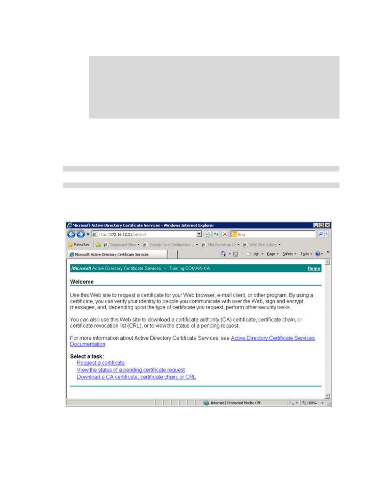
Data Security
For example:
Country Name (2 letter code) [AU]:US
State or Province Name (full name) [Some-State]:NY
Locality Name (eg, city) []:Buffalo
Organization Name (eg, company) [Internet Widgits Pty Ltd]:Dialogic
Organizational Unit Name (eg, section) []:Dialogic Research
Common Name (eg, YOUR name) []:sba1.training.com
Email Address []:
Please enter the following 'extra' attributes
to be sent with your certificate request
A challenge password []:
An optional company name []:
If the openssl requests are successful, the CA places two security files into the
directory you created in Step 2 (c:\Keys\SBA1).
2. Access the Microsoft
®
Active Directory Certificate Services website from any machine
in the domain where the Lync Front End Server is installed. The domain and IP
address will vary, depending on the installation. For example:
http://domain/certsrv
http://172.16.12.21/certsrv
3. Log into the Microsoft Active Directory Certificate Services website with Administrator
rights.
The Microsoft Active Directory Certificate Services website appears:
4. Click Request a certificate.
The Request a Certificate page appears:
79
Page 88
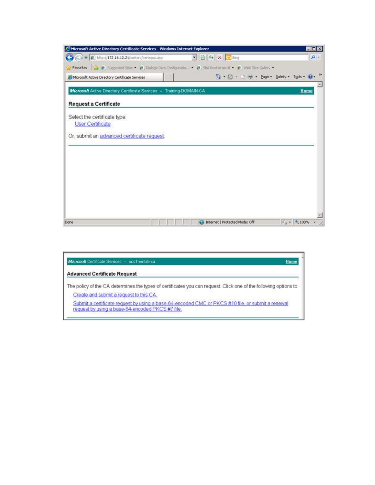
Dialogic 4000 Media Gateway Series SU4.1 Reference Guide
5. Click advanced certificate request.
The Advanced Certificate Request page appears:
6. Select the second option, Submit a certificate request by using a base-64-
encoded CMC or PKCS #10 file, or submit a renewal request by using a base64-encoded PKCS #7 file.
7. Open the certificate request file with Wordpad. (In the following example, this file is
called request.csr, and it resides in the c:\keys\sba1 directory.) Select all file
contents (everything between BEGIN CERTIFICATE REQUEST to END CERTIFICATE
REQUEST), as shown below:
80
Page 89
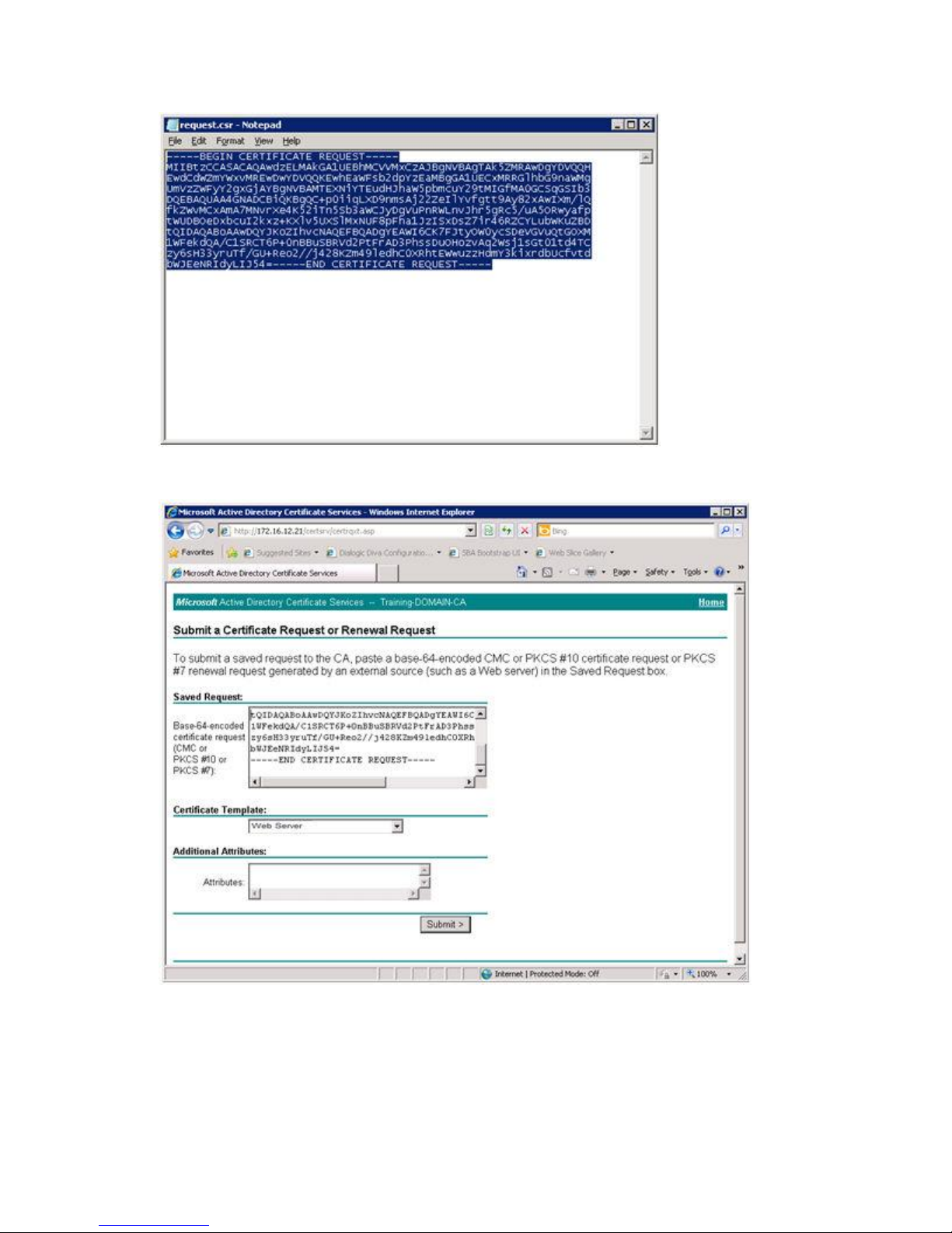
Data Security
8. Paste the contents into the Saved Request section of the Microsoft Active Directory
Certificate Services website, and select Web Server in the Certificate Template field:
9. Click Submit.
If the certificate creation is successful, the Microsoft Active Directory Certificate
Services download page appears.
81
Page 90
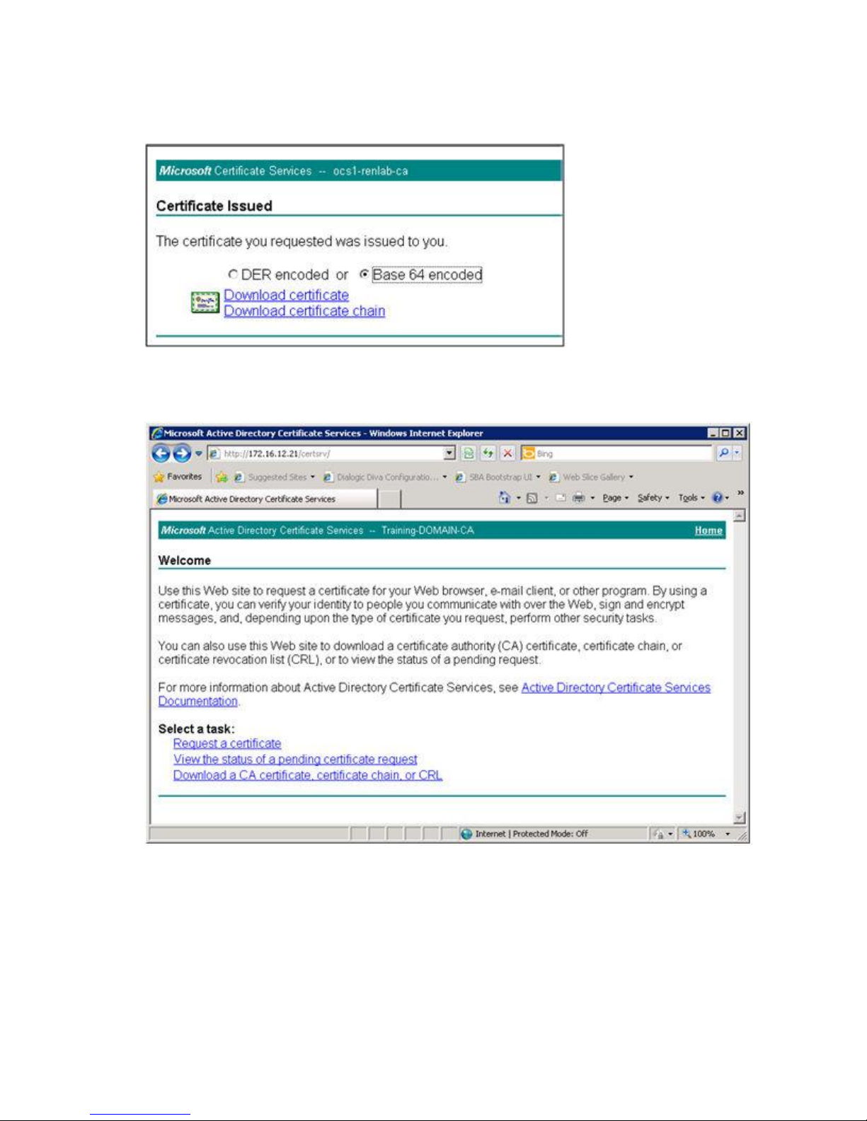
Dialogic 4000 Media Gateway Series SU4.1 Reference Guide
10. On the Microsoft Active Directory Certificate Services download page for signed
certificates, select BASE 64 encoded, and click Download certificate:
11. In the File Download dialog box, select Save This File to Disk and click OK. The saved
file is the Certificate File for Diva SIPcontrol.
12. Go back to the Microsoft Active Directory Certificate Services home page:
13. Click Download a CA certificate, certificate chain, or CRL.
The Download a CA Certificate, Certificate Chain, or CRL page appears:
14. Select Base 64, and click the text in the CA certificate field.
15. Save the downloaded file. The saved file is the Certificate Authority file
(certAuth.cer).
82
Page 91
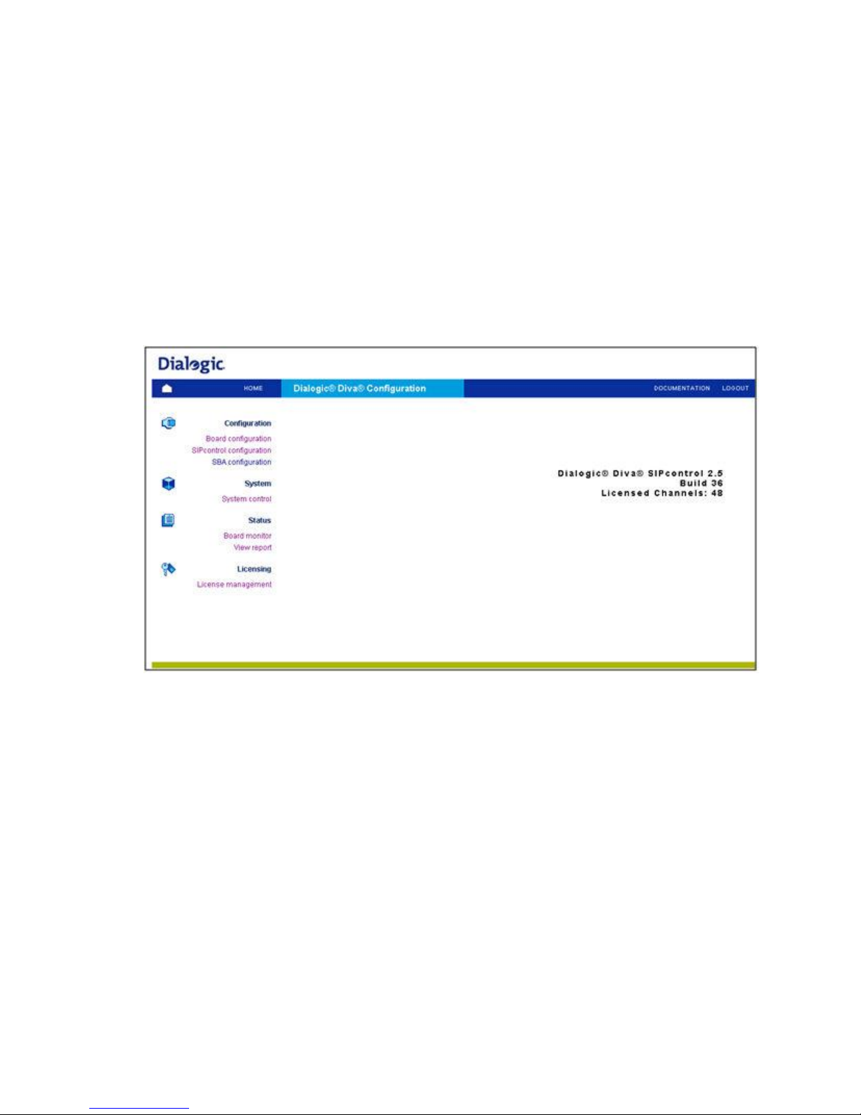
Data Security
Uploading the Certificate Authority, Certificate, and Key
Files to Dialogic® Diva® SIPcontrol™
Once you generate the key files and certificate request file, upload them to Diva SIPcontrol,
as described in the steps below:
1. Click Start > Programs > Dialogic Diva > SIPcontrol Configuration to access
the Diva SIPcontrol web interface. By default, access to the web interface is only
allowed from local host (127.0.0.1), and the port number to which the server is
listening is set to 10005.
The Diva web interface login page appears.
2. In the Password field, enter Dialogic.
The Dialogic® Diva® Configuration page appears:
3. Click SIPcontrol configuration on the left hand side.
The SIPcontrol Configuration page appears.
4. Click Security Profiles (about halfway down the page), and then click Details to
open the Security Profiles options:
83
Page 92
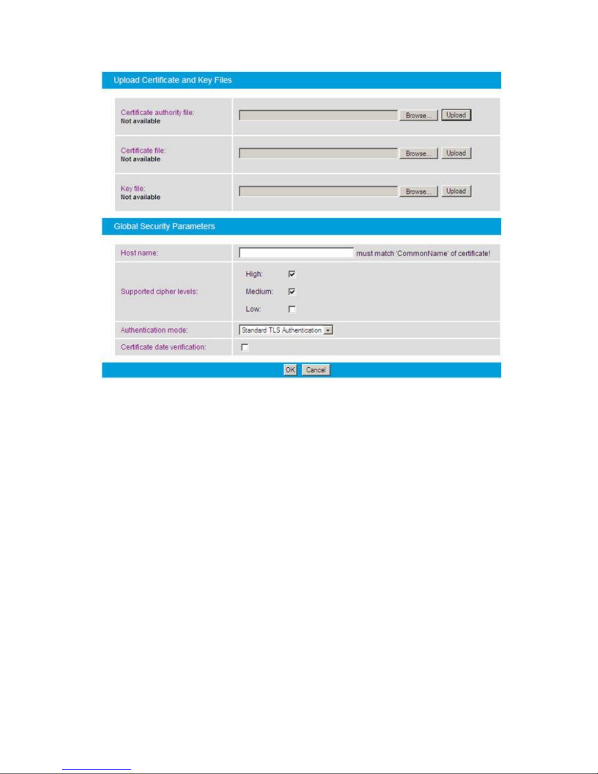
Dialogic 4000 Media Gateway Series SU4.1 Reference Guide
5. In the Certificate authority file field, use Browse to locate the Certificate Authority
file (certAuth.cer).
6. Click Upload to upload the certAuth.cer file to Diva SIPcontrol.
A message box appears.
7. Click OK to upload the file.
8. Repeat Steps 5 – 7 for the Certificate file and Key file.
9. In the Authentication mode field (in the Global Security Parameters section), select
how the server-client authentication should be handled.
10. Click OK at the bottom of the page to close the Security Profiles window.
11. At the bottom of the SIPcontrol main page, click Activate Configuration to save the
configuration.
12. Restart Diva SIPcontrol to use the new configuration. Click System Control on the
left side of the web interface, and then click Restart in the SIPcontrol field.
84
Page 93
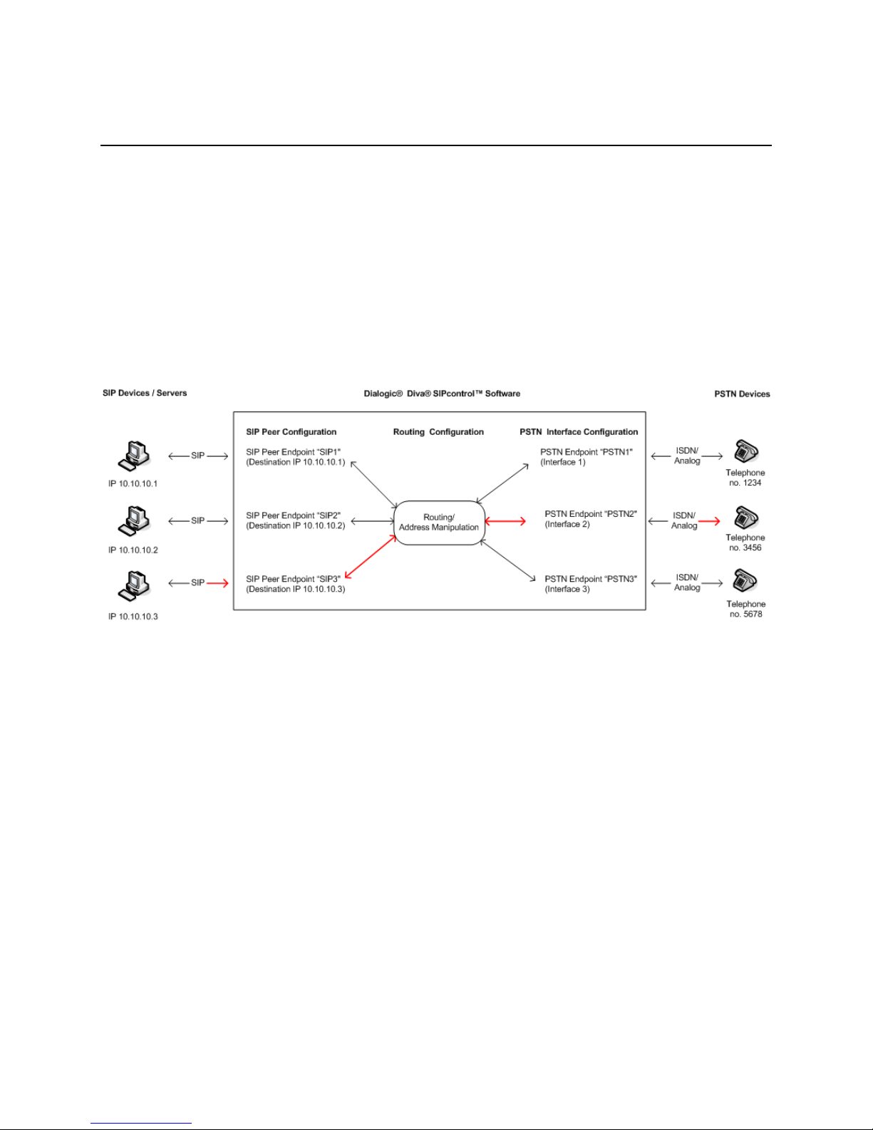
7. How Calls are Processed
How Calls are Processed
In the following discussion, SIP and PSTN endpoints/interfaces are interchangeable, and
they may be used on no, one, or two sides of the call.
Diva SIPcontrol uses an endpoint-based approach to process calls, which means that every
PSTN interface and every configured SIP peer is considered as a single endpoint. The
endpoint holds Diva SIPcontrol settings for the respective PSTN interface or SIP peer. Each
call originates at a specific endpoint (on the SIP side after assigning the SIP call request to
one of the configured peers) and needs a route to find its designated endpoint (the
destination). Thus, the most simple configuration needs two endpoints of any type and one
route, as shown in red in the graphic below.
This graphic shows that an endpoint is only a virtual object of a real device. The endpoint
holds the settings for the corresponding device. For example, if a call should be routed from
SIP Device 3 to PSTN Device 2 as marked red in the graphic, then the:
Settings of SIP Device 3 need to be configured as a SIP peer endpoint in the SIP
Peers section.
Settings PSTN Device 2 needs to be configured as a PSTN endpoint in the PSTN
Interfaces section.
Condition "called address is 3456" needs to be configured in the Routing section to
route the call to the correct device.
For example, if you have a SIP or PSTN Device 4 with no endpoints configured in Diva
SIPcontrol, you cannot establish a call, because Diva SIPcontrol will not know the settings of
the device.
85
Page 94

Dialogic 4000 Media Gateway Series SU4.1 Reference Guide
The PSTN endpoint is found via its controller number. On the SIP side, multiple SIP peers
can connect via the same network interface. Therefore, the assignment is more complex:
1. The host/domain name and port number of the received "FROM" header is compared
against the SIP peer settings.
2. If no host matches, the same address is compared against the "Domain" parameters
of the SIP peers.
3. If no match is found, Diva SIPcontrol looks for a SIP peer with the Default SIP Peer
option enabled.
4. If the call cannot be assigned, regardless of whether the call originated in the PSTN
or SIP network, the call is rejected.
Every route defines only one direction. Therefore, at least two routes are needed to support
both PSTN-to-SIP and SIP to PSTN connections. The basic call (without address
manipulation) is processed as follows:
86
Page 95
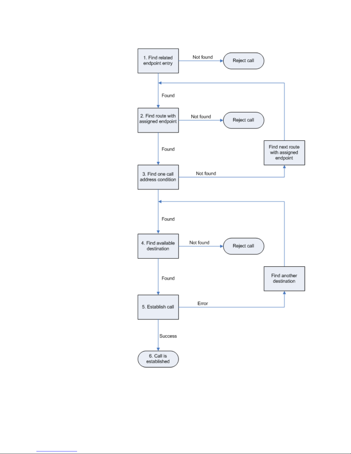
1. Find and assign an
endpoint for an
incoming call request
(PSTN: lookup by CAPI
controller number; SIP:
lookup by "From"
address of received
message).
2. Go sequentially through
the list of routes and
find the first route that
has this endpoint
defined in its configured
sources list.
3. Determine whether at
least one call address
condition of this route
matches simultaneously
the called, calling, and
redirected addresses of
the call request; if not,
find another route.
4. If any route condition
matches, verify in the
list of configured
destinations which one
is the most preferred.
This is done based on
settings. See
Information about Call
Processing below for
more information.
5. Try to establish the call
via this destination. If
the destination is
unavailable or rejects
the call, try the next
destination of the route.
Note that the call will be
aborted immediately if a
cause code is received
that signals final failure,
e.g., user busy or
unallocated number.
6. The call is established.
How Calls Are Processed
87
Page 96

Dialogic 4000 Media Gateway Series SU4.1 Reference Guide
Information about Call Processing
Each route can point to several destinations, between which Diva SIPcontrol chooses
according to the following settings (in decreasing order of importance):
o Availability (destination enabled)
o Alive state of destination (if enabled to be verified)
o Priority (Master/Slave)
o Channel load quota (a factor calculated by comparing used vs. total supported
channels)
For each call, only one route is chosen. Even if another route also matches the call
criteria, only the first matching route is ever evaluated. Therefore, default routes
should be created carefully and located at the end of the routing table, if
appropriate.
Load balancing/failover is only performed between the destinations of a single route.
Routes without any conditions always match (as long as the source endpoint is listed
in route sources).
Emergency Calls
In many environments, certain numbers, e.g., 110/112 in Germany or 911 in the U.S., have
to be handled differently from others. For example, they might need to be dialed without
any access digit.
This can be achieved by creating an additional route from any configured SIP peers to one
or more PSTN interfaces and setting the called address condition to the emergency
number(s). The route should be placed at the top position in the list. Should there be a
dialplan and/or address map configured for the respective PSTN interfaces, it may be
necessary to add another regular expression to the address maps of the interfaces to handle
those calls.
Routing Conditions
Diva SIPcontrol organizes the conditions of a route in a list. Each list entry consists of
different expressions for called, calling, and redirected address. The route matches only if all
three expressions simultaneously match the respective call addresses. Empty expressions
are considered to match, so there is no need to add wildcards into unused expressions. As a
result, if a call should match either a called address or a calling number, two list entries
have to be created, with called expression in the first and calling expression in the second
row. If both have to match concurrently, both expressions have to be entered into the same
list entry.
Routing Examples
This section describes the configuration of four possible routing scenarios:
Direct Routing between One PSTN Interface and One SIP Peer
Connecting Two SIP Peers to Two PSTN Interfaces Exclusively
Connecting Two SIP Peers to the Same PSTN Interface
Load Balancing or Failover between Two SIP Peers
88
Page 97

How Calls Are Processed
Direct Routing between One PSTN Interface and One SIP Peer
If you choose to route all calls from the PSTN to the same SIP peer, and calls from that SIP
peer to the PSTN, configure the parameters as follows. For this configuration, no address
rewriting is done:
1. Under PSTN Interfaces, enable and configure all PSTN interfaces connected to a
PBX. Confirm each dialog box with OK.
2. Under SIP Peers, create a SIP peer with the necessary settings, and make sure that
the option Default peer for received SIP calls is enabled. Confirm with OK.
3. Under Routing, create Route 1 and do the following:
Select each required PSTN interface as a source peer.
Select the SIP peer configured in Step 2 as a Master destination.
Set the Number format field to Unchanged.
Confirm with OK.
4. Under Routing, create Route 2 and do the following:
Enable the SIP peer configured in Step 2 as a source peer.
Enable all required PSTN interfaces as Master destinations.
Set the Number format field to Unchanged.
Confirm with OK.
5. Save the configuration in the main configuration interface.
Direct Routing between Two SIP Peers
If you choose to route all calls from the PSTN to the same SIP peer, and calls from that SIP
peer to the PSTN, configure the parameters as follows. For this configuration, no address
rewriting is done:
1. Under SIP Peers, create one SIP peer with the necessary settings, and make sure
that the option Default peer for received SIP calls is enabled. Confirm with OK.
2. Under SIP Peers, create the other SIP peer with the necessary settings. Confirm with
OK.
3. Under Routing, create Route 1 and do the following:
Select the SIP Peer configured in Step 1 as a source peer.
Select the SIP peer configured in Step 2 as a Master destination.
Set the Number format field to Unchanged.
Confirm with OK.
4. Under Routing, create Route 2 and do the following:
Select the SIP peer configured in Step 2 as a source peer.
Select the SIP peer configured in Step 1 as a Master destination.
Set the Number format field to Unchanged.
Confirm with OK.
5. Save the configuration in the main configuration interface.
89
Page 98

Dialogic 4000 Media Gateway Series SU4.1 Reference Guide
Connecting Two SIP Peers to Two PSTN Interfaces Exclusively
If you choose to connect two SIP peers to two PSTN interfaces, so that each SIP peer can
use one interface exclusively, then carry out the following configuration steps. The
procedure is similar if you need to configure more PSTN interfaces, e.g., three PSTN
interfaces to three SIP peers.
1. Under PSTN Interfaces, enable and configure the two PSTN interfaces. Confirm
with OK.
2. Under SIP Peers, create both SIP peers and make sure the entry in Domain
exactly matches the domain used by the SIP peer in its SIP address for outgoing
calls. Do not enable the option Default peer for received SIP calls for any of
these peers. Confirm with OK.
3. Under Routing, create Route 1 and do the following:
Enable the first PSTN interface as a source peer.
Enable the first SIP peer configured in Step 2 as a Master destination.
Confirm with OK.
4. Under Routing, create Route 2. Then, repeat Step 3 for the second PSTN interface
and the second SIP peer.
5. Under Routing, create Route 3 and do the following:
Enable the first SIP peer configured in Step 2 as a source peer.
Enable the first PSTN interface as a Master destination.
Confirm with OK.
6. Under Routing, create Route 4. Then, repeat Step 5 for the second PSTN interface
and the second SIP peer.
7. Save the configuration in the main configuration interface.
Connecting Two SIP Peers to the Same PSTN Interface
If you want to connect two SIP peers to the same PSTN interface so that all calls from the
PSTN are sent to the first SIP peer if the numbers begin with "1" and to the second peer if
the numbers begin with "2", configure the parameters as follows:
1. Under PSTN Interfaces, enable and configure the PSTN interface. Confirm with OK.
2. Under SIP Peers, create both SIP peers and make sure the entry in Domain
matches exactly the domain used by the SIP peer in its SIP address for outgoing
calls. Do not enable the option Default peer for received SIP calls for any of
these peers. Confirm with OK.
3. Under Routing, create Route 1 and do the following:
Enable the first PSTN interface as a source peer.
Enable the first SIP peer configured in Step 2 as a Master destination.
Under Conditions, click Add and set the Called address to "1.*".
Confirm with OK.
4. Under Routing, create Route 2 and repeat Step 3 for the second SIP peer with the
only difference that the called address condition for this route is "2.*".
90
Page 99

How Calls Are Processed
5. Under Routing, create Route 3 and do the following:
Enable both SIP peers as source peers.
Enable the first PSTN interface as a Master destination.
Confirm with OK.
6. Save the configuration in the main configuration interface.
If calls other than those beginning with 1 or 2 should also be directed to one peer, remove
the condition from the respective PSTN to SIP route and move the route to the end of the
list.
Load Balancing or Failover between Two SIP Peers
To configure two servers for load balancing or failover, follow these steps:
1. Under PSTN Interfaces, enable and configure all required PSTN interfaces. Confirm
with OK.
2. Under SIP Peers, create both SIP peers and make sure the entry in Domain exactly
matches the domain used by the SIP peer in its SIP address for outgoing calls. Do
not enable the option Default peer for received SIP calls for any of these peers.
If you configure a failover, SIP peer 1 (a Master) should have the option Alive
check enabled. Confirm with OK.
3. Under Routing, create Route 1 and do the following:
Enable the first PSTN interface as a source peer.
Enable the first SIP peer configured in Step 2 as a Master destination. For
load-balancing configurations, SIP peer 2 should be configured as a Master
destination. For failover configurations, it should be configured as a Slave
destination.
Confirm with OK.
4. Under Routing, create Route 2 and do the following:
Enable both SIP peers as source peers.
Enable the first PSTN interfaces as a Master destination.
Confirm with OK.
5. Save the configuration in the main configuration interface.
6. Under Routing, create Route 2 and repeat Step 3 for the second SIP peer with the
only difference that the called address condition for this route is 2.*.
7. Under Routing, create Route 3 and do the following:
Enable both SIP peers as source peers.
Enable the first PSTN interface as a Master destination.
Confirm with OK.
8. Save the configuration in the main configuration interface.
If calls other than those beginning with 1 or 2 should also be directed to one peer, remove
the condition from the respective PSTN to SIP route and move the route to the end of the
list.
91
Page 100

This page intentionally left blank
 Loading...