

Page 1
D/41JCT-LS
n Installation
n Warranty Period
n RMA Procedure
Part Number 05-1352-001
Copyright © 2000
Dialogic Corporation
All Rights Reserved
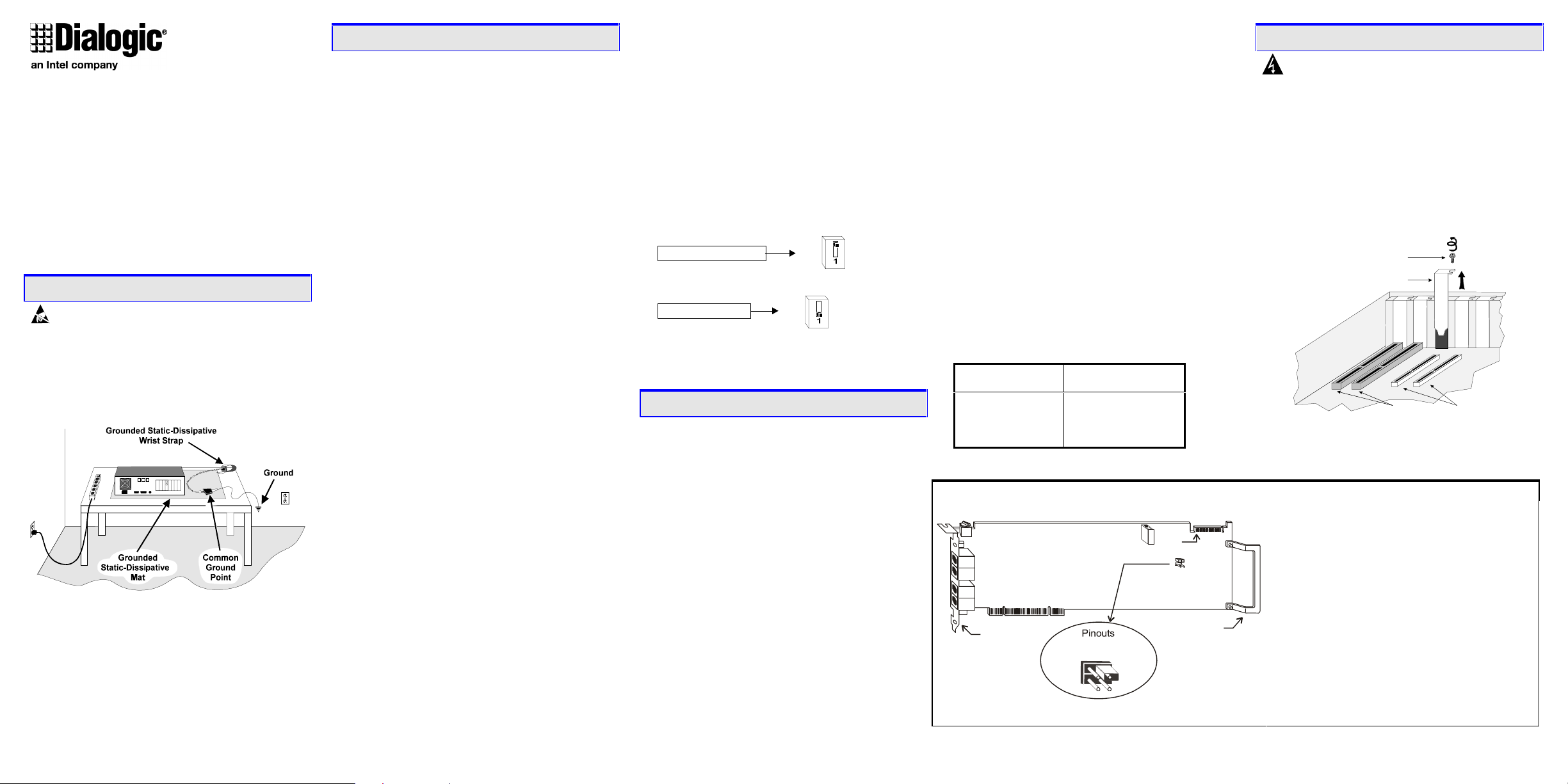
1. Protect Boards from Damage
Caution! Computer boards are static-sensitive and
can be damaged by touching or handling. To prevent
damage from static electricity, do the following:
• Wear a grounded, static-dissipating wrist strap for
the entire hardware installation.
• Work at a static-safeguarded work station (see
below).
The work surface drains electrical charges from
conductive materials when the materials are placed on
the surface. The grounded, static-dissipating wrist strap
drains static charge from the person wearing the strap.
Both components ensure that static charges are drained
at a rate and current level that are safe. Both must be
used any time a person is handling a board or
component.
2. Set Hardware Switches
The D/41JCT-LS board includes hardware autoconfiguration for IRQ and memory address. This
technology lets you use the factory default hardware
settings for quick installation and operation. However,
we recommend that you review the following
information before installing your board and select any
options as desired.
A. Set the Board ID Number
When you start Dialogic boards, each board is assigned
a sequential number for identification and use by the
system software. This sequential number specifies the
device and channel name(s) for each board. The board
number is based on the board ID that you set using the
SW30 rotary switch on the board.
Use the SW30 rotary switch to specify board
sequencing as follows:
• Automatic Assignment: Board ID 0
Also called geographical method. All Dialogic PCI
boards can share the factory default setting of board
ID 0. In this case, boards are automatically sorted by
PCI bus and slot number.
Note: Adding or removing a board can cause the
renumbering of boards in the system. Consequently,
the assignment of device names may change during
the next system start-up.
• Manual Assignment: Board IDs 1–9, A-F
In addition to the automatic assignment method, you
can use the manual or discrete assignment method to
further identify boards in your system.
If you change the board ID from the factory default
of 0 to any other number, the software will use that
setting to identify the board.
Note: When not set to 0, the board ID must be
unique. It must not conflict with the board ID of any
other Dialogic ISA or PCI board. If you use this
method, we recommend that you assign sequential
numbers starting at 1. This method is also used for
all ISA bus boards.
Numbering Precedence in Mixed Systems
In systems using both automatic and manual assignment
methods, or where both ISA and PCI boards exist, PCI
boards take precedence and are numbered before an
ISA board that uses board IDs 1-9 or A-F.
Note: The Dialogic software can correctly register your
boards for proper operation; however, due to variations
among computer chassis, it is not possible for the
software to determine where each board is physically
placed. For more information on board ID numbering
issues, see the Dialogic Installation and Configuration
Guide for your operating system or visit the Dialogic
Technical Support website at
http://support.dialogic.com/tnotes/tnbyos/winnt/tn187.htm .
B. Set the Hook-Switch State for Start-Up
(Optional)
Set the SW4 switch as follows to select how the board
responds to an incoming call when the computer power
is on but the board is not initialized.
SW4
ON
SW4
OFF
Ringing (On-Hook)
SW4 = Off (default): Callers hear ringing (on-hook).
Busy (Off-Hook)
SW4 = On: Callers hear a busy signal (off-hook).
If the computer power is off, callers hear ringing
Note:
(on-hook) regardless of the setting of the SW4 switch.
3. Set CT Bus Jumpers (optional)
The Computer Telephony bus (CT Bus) provides
communication and flexible resource sharing among the
boards connected to the bus. This Dialogic board has a
CT Bus connector that complies with the ECTF H.100
specification, and as such can be connected to the
CT Bus with a CT Bus cable.
You can connect the board to the CT Bus or use it
without the CT Bus in stand-alone mode.
n Stand-Alone Mode (CT Bus Jumpers Ignored):
For applications that do not require media sharing or
switching across the CT Bus, use the board in standalone mode. No CT Bus cable is required. You can
skip the rest of this section and proceed to Section 4
“Install the Board.”
In addition, you may skip the instructions in this
section when you use the board in SCbus mode
without a CT Bus master board; that is, using only
SCbus master/slave boards.
n CT Bus Mode (CT Bus Jumpers Needed): To
connect the boards to the CT Bus, set the CT Bus
jumpers according to instructions in this section.
Note: If these boards are operating in SCbus mode, CT
Bus (H.100) termination is not required.
The following instructions only apply to the boards at
each end of the CT Bus cable. Only boards at each end
of the CT Bus cable must be terminated.
JP1 jumper is reserved and unused. DO NOT install a
shunt across the pins of JP1.
JP2 is a 2-pin jumper that is used to terminate the CT
Bus, ensuring that proper electrical characteristics exist
on the CT Bus. By factory default, this jumper is not
terminated on the board.
To use the CT Bus:
• Install the shunt on the JP2 jumper of a board to
terminate the CT Bus at that board.
• Only terminate the first and last boards (the boards
located at each end) on the CT Bus cable.
• Do not install a shunt across the pins of JP2 on
boards located between the end boards on the CT
Bus cable (the shunt must be disconnected on the
JP2 jumper to disable termination).
The JP2 jumper terminates the H.100 signals listed in
the following table.
H.100 signal
Shunt
JP2, Pins 1 and 2
(used on boards at
each end of CT Bus
cable only)
SW30 SW4
J1
J2
J3
J4
PCI bus connect or
rear bracket
terminated
CT_FRAME_(A&B)
CT_C8_(A&B)
slot retainer bracket
JP2 (top row, pins 1 and 2)
JP1 (bottom row, pins 1 and 2)
21
12
Physical Description
CT Bus connector
Pin 1
JP2
JP1
4. Install the Board
Warning! To reduce the risk of electric shock:
• Switch off the power and disconnect all power
cords.
• Do not re-attach power cords or switch on power to
the computer while the computer cover is removed.
Install the board in the computer chassis according to
the following instructions:
1. Remove the computer cover.
2. Select an empty PCI bus slot, and remove the slot’s
retaining screw and access coverplate.
Retaining Screw
Metal Coverplate for Slot
16-Bit ISA Slots
Note: If you are not installing your board in an ISA
form-factor PCI slot, remove the slot retainer bracket
from the end of the board before installation.
Part Function
SW30 Rotary switch to set board ID number
SW4 Switch to set hook-switch state for start-up
J1–J4 RJ-11 jacks to connect to PBX or Central
Office lines
JP1 Jumper reserved.
JP2 Jumper to terminate CT Bus on board at
each end of CT Bus cable (factory default
is unterminated)
CT Bus connector
ECTF H.100-compliant CT Bus edge
connector
PCI bus connector
PCI expansion bus edge connector
32-Bit PCI Slots
Page 2
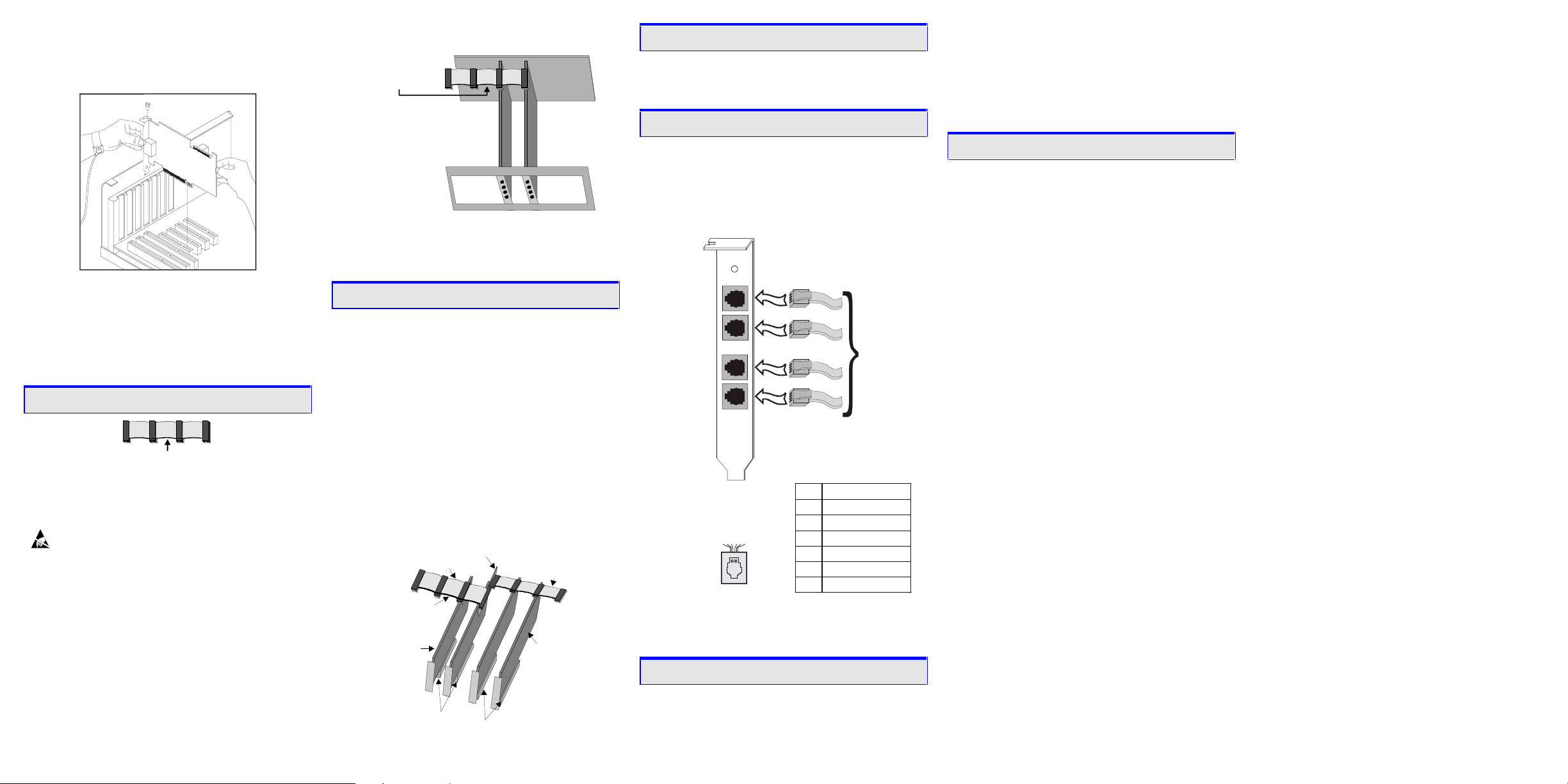
3. Insert the board’s edge connector into the bus slot.
Use the slot’s board guides as you insert the board
edge connector into the slot. Apply pressure only to
the top edge of the board, and press firmly until the
edge connector is securely seated in the slot.
4. Replace and tighten the retaining screw to secure the
board. If the screw is not installed and you attach a
CT Bus cable to the board, the board may be
accidentally unseated from the slot.
5. To install an additional board, select an empty PCI
slot adjacent to the location of the previous board,
and repeat (the second part of) step 2 through step 4.
5. Attach CT Bus Cable to Board (optional)
ColoredStripe(Pin1)
If you use the board in stand-alone mode, skip the
instructions in this section.
Use a CT Bus cable to connect your board to other
CT Bus form-factor boards in the system.
Caution! To preserve the electrical integrity of the
CT Bus, use a CT Bus cable with the appropriate
number of connectors (“drops”). We recommend that
no more than two connectors at either end of the cable
be left unused. In addition, it is preferable to distribute
the installed boards in slots along the length of the
CT Bus cable rather than clustered in one area.
Attach the CT Bus cable to the Dialogic board as
follows:
1. Attach the end connector on the CT Bus cable to the
CT Bus edge connector on the top edge of the first
board in the sequence. The connectors are designed
to fit together one way only. If the connector does
not seat fully on the board, turn the cable around and
try again. Make sure that the colored stripe on the
cable faces the rear bracket.
2. Attach the cable to the next board until all boards are
connected by the cable.
Colored Str ipe
(Pin 1)
Your CT Bus cable may
have a different number
of connectors (drops) .
3. If the cable has extra connectors or is loose, tuck the
cable down so that it does not snag when you
replace the computer cover. See the Caution given
earlier in this section.
6. Connect CT Bus/SCbus Adapter (optional)
If you use the board in stand-alone mode, skip the
instructions in this section.
To connect your board to SCbus form-factor boards,
use the CT Bus/SCbus adapter (part number
99-2446-001). You may use only one CT Bus/SCbus
adapter per system.
1. Before installing the adapter, the Dialogic boards in
your chassis must be positioned in the correct order.
The board on which the adapter is installed must be
inserted in the first PCI slot adjacent to an ISA slot.
Locate this board.
2. Align pin 1 of the adapter with pin 1 of the edge
connector on the board. Press the adapter onto the
board with the SCbus cable connector facing the rear
edge of the board.
CT Bus / SCbus
CT Bus
Cable
Colored Stripe
(Pin 1 Indicator)
D/xxx JC T
Board
PCI Slots
For more information, see the hardware installation
instructions for the CT Bus/SCbus Adapter.
Adapter
ISA Slots
D/xxx
Board
SCbus
Cable
7. Complete Boar d Installation
After you have installed the board(s) and if applicable
attached cables and adapter, replace the computer cover
and re-attach power cords.
8. Connect External Cables
• Each RJ-11 jack on the rear bracket of the voice
board supports a single voice channel. Use each RJ11 jack and phone cable to connect each channel to
an analog PBX or standard telephone outlet.
• Since this board emulates a standard telephone, a
standard telephone will not function when directly
attached to the board.
Rear
bracket
on board
Channel 1
Channel 2
Channel 3
To analog
PBX
or
standard
telephone
outlet
Channel 4
J1-J4 on the
D/41JCT-LS Board
RJ-11 Connector
254361
Pin
1
2
3
4
5
6
Note: Connect the Earth Recall signal to pin 2. DO
Signal
Unused
Station - Earth Recall
Station - Ring
Station - Tip
Unused
Unused
NOT connect Tip or Ring lines to pin 2 or improper
operation of the D/41JCT-LS will result.
9. Install Software, Configure and Test
Install the Dialogic software release and configure the
Dialogic boards as described in the Dialogic
Installation and Configuration Guide for your operating
system.
Your application software or Dialogic software release
may have special installation or configuration
requirements. Be sure to read your software
documentation including release note information
before you install the software.
Note: If you are adding hardware to an existing system,
you do not need to uninstall existing Dialogic software.
Warranty and Return Information
For technical specifications and product information,
visit the Dialogic website, http://www.dialogic.com, or
use the Dialogic On-Line Information Retrieval System
at 1-800-755-5599 or 1-973-993-1063.
Warranty Period
This Dialogic board has a 3-year warranty. See the
Hardware Limited Warranty on the back of the
Regulatory Notice for coverage details.
Repair of Merchandise Authorization (RMA)
Process
1. Before completing the RMA process, verify that
the problem is not due to a mistake or oversight in
the installation process. Choose one of the
following methods:
• On the Web, go to the Dialogic FirstCall
Server at http://support.dialogic.com and
browse through the various topics.
• If you have a Dialogic Support Plan, contact
one of our Technical Support Departments
listed below and they will troubleshoot the
problem over the phone.
The Americas
973-993-1443
Continental Europe, Middle East, Africa
+32-2-712-4321
Southeast Asia, West Asia, and
Australia/New Zealand
+65-339-9833
For more information and a complete list of
Worldwide Technical Support centers, visit:
http://www.dialogic.com/support/tech.htm
2. After you have determined that you have a problem
board, do one of the following:
• For Dialogic products purchased outside of the
United States or Canada, contact your local
Dialogic Sales Office for RMA procedures.
TM
Info
•
For Dialogic products purchased from a
distributor, the distributor owns the warranty
and you MUST go through them if you do not
want to be charged for the repair.
Note:
You may return the board to Dialogic for
repair, even if you did not purchase your board
through the Dialogic Corporate Sales Office.
However, if the repairs are not authorized by
your local distributor or local Dialogic Sales
office, the board is considered “out of
warranty” and a fee is charged for repair
services.
• Go to the Dialogic Technical Support website
at http://support.dialogic.com/rma, and fill out
the Repair of Merchandise Authorization form.
1) To complete the RMA form, you will need
the serial number of the board. This
information must be given at the time of the
return or the request cannot be processed.
2) Observe correct static-safe handling
procedures. Disconnect power cables and
remove the board from the chassis.
3) Record the serial number (two letters
followed by numeric digits, and located on
a label on the board).
4) Include your Service Request Number
given to you by a Technical Support
representative, if appropriate.
5) E-mail the RMA form to the RMA
Department.
3. After you receive an RMA number from Dialogic,
return the problem board to Dialogic as outlined in
the steps below:
a. Pack the board(s) in their original anti-static
packaging and protected packaging.
b. Clearly display the RMA number on the
package. If this number is not on your
package, it will be treated as an unauthorized
return.
Note: Dialogic is not responsible for risk of
loss or damage in transit.
c. Ship the board to the Dialogic address listed
below:
Dialogic
1515 Route 10
Parsippany, NJ 07054 USA
ATTN: RMA#
 Loading...