

Page 1

User manual
UM-DA7202 evaluation board
DA7202 10 W mono class D ampl i fi er for 2S
systems
Abstract
This user manual enables you to use the UM-DA7202 class D speaker driver evaluation board, 18901-A EVB, to carry out performance measurements and functional checks on the DA7202 class D
speaker driver.
Page 2

DA7202 10 W mono class D amplifier for 2S systems
UM-DA7202 evaluation board
Contents
Abstract ................................................................................................................................................ 1
Contents ............................................................................................................................................... 2
Figures .................................................................................................................................................. 2
Tables ................................................................................................................................................... 2
1 Terms and definitions ................................................................................................................... 3
2 References ..................................................................................................................................... 3
3 Introduction.................................................................................................................................... 4
4 DA7202 EVB hardware description ............................................................................................. 5
4.1 Power suppl y ......................................................................................................................... 7
4.2 Analogue input ...................................................................................................................... 7
4.2.1 Lower gain configuration........................................................................................ 7
4.2.2 Single-ended input ................................................................................................. 7
4.3 Speaker output ...................................................................................................................... 7
4.3.1 Additional filtering .................................................................................................. 7
5 Schematic diagram ....................................................................................................................... 8
6 Bill of materials .............................................................................................................................. 9
7 Revision history .......................................................................................................................... 11
Figures
Figure 1: DA7202 performance EVB ..................................................................................................... 4
Figure 2: DA7202 performance EVB external connections ................................................................... 5
Figure 3: Schematic diagram................................................................................................................. 8
Tables
Table 1: Connector summary ................................................................................................................ 6
Table 2: Order BOM for a single EVB ................................................................................................... 9
Table 3: Build BOM - populated components...................................................................................... 10
Table 4: Document revision history ..................................................................................................... 11
User Manual Revision 2.0 28-Mar-16
CFR0012 2 of 12 © 2016 Dialog Sem iconductor
Page 3

DA7202 10 W mono class D amplifier for 2S systems
UM-DA7202 evaluation board
1 Terms and definitions
GND Ground Reference
EVB Evaluation Board
EMI Electromagnetic Interference
PCB Printed Circuit Board
USB Universal Serial Bus
PSRR Power Supply Rejection Ratio
2 References
[1] DA7202, Datasheet, Dialog Semiconductor
User Manual Revision 2.0 28-Mar-16
CFR0012 3 of 12 © 2016 Dialog Sem iconductor
Page 4
DA7202 10 W mono class D amplifier for 2S systems
UM-DA7202 evaluation board
3 Introduction
DA7202 is a powerful, highly efficient, low EMI Class D speaker driver that can drive 10 W into 4 Ω
loads directly from a 2S lithium-ion battery to power a variety of two cell portable applications such as
Ultrabooks™ and tablets.
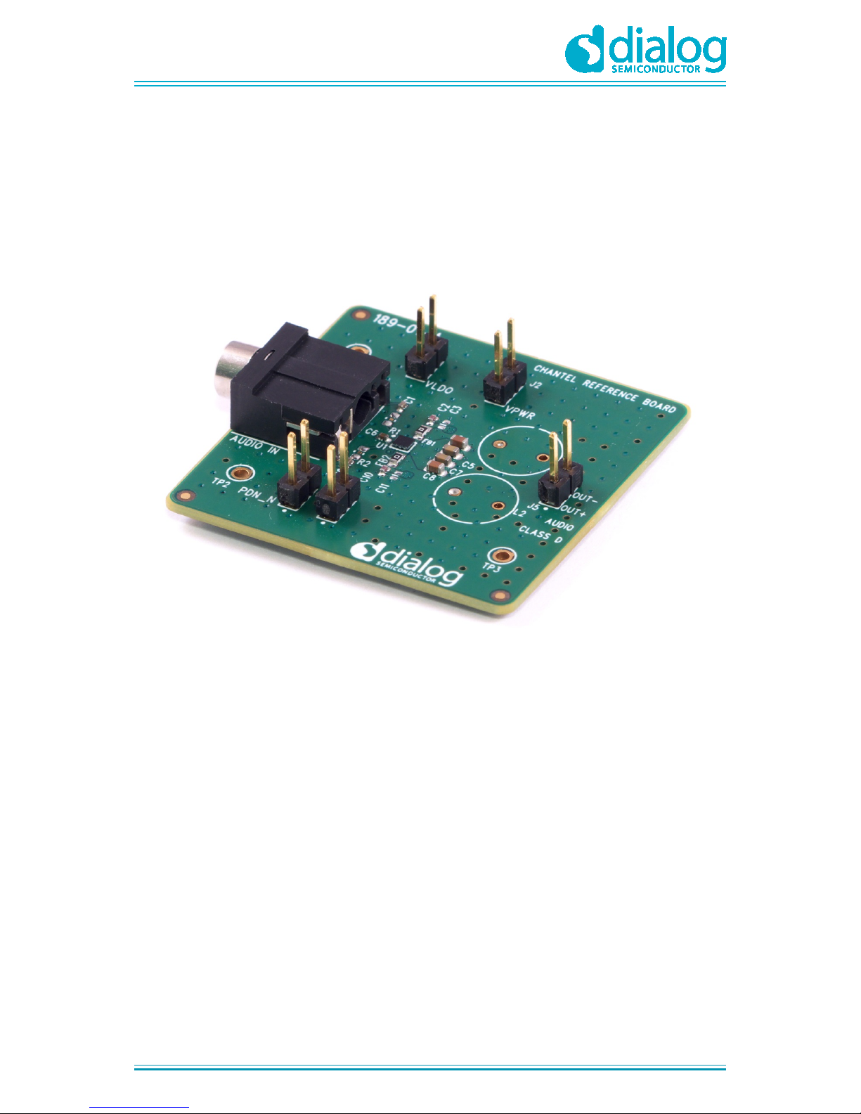
The DA7202 performance evaluation board (189-01-A) has been produced to allow measurement
and evaluation of the DA7202 device.
The evaluation board (EVB) is supplied with a USB memory stick containing supporting collateral.
Figure 1: DA7202 performance EVB
User Manual Revision 2.0 28-Mar-16
CFR0012 4 of 12 © 2016 Dialog Sem iconductor
Page 5

DA7202 10 W mono class D amplifier for 2S systems
UM-DA7202 evaluation board
4 DA7202 EVB hardware description
The DA7202 EVB consists of the DA7202 device, the essential external components and connection
points for input / output signals. Typical external connections are shown in Figure 2.
The EVB can be used standalone or as a module for interface to a customer development platform.
Differential Line Input
+
VPWR=
4.5V – 10V
1
2
3
+
PDN =
1.3V – 5.5V
Shorting point J7 to disable device
Figure 2: DA7202 performance EVB external connections
User Manual Revision 2.0 28-Mar-16
CFR0012 5 of 12 © 2016 Dialog Sem iconductor
Page 6

DA7202 10 W mono class D amplifier for 2S systems
UM-DA7202 evaluation board
Table 1: Connector summary
Connector Functionality Description
J1 Internal VLDO monitoring VLDO (No external connection needed)
Pin 1 = GND
Pin 2 = LDO output
J2 VPWR external power
supply connection
VPWR
Pin 1 = 0 V/GND
Pin 2 = +4.5 V to +10.0 V
J3 AUDIO IN Differential line input via 3-pole, 3.5 mm jack so ck e t
Ring = IN+
Tip = INSleeve = GND
J4 AUDIO IN (optional input) Differential line input connection points accessible via the
underside of the board or by removing J3
Pin 1 = 0 V/GND
Pin 2 = IN+
Pin 3 = IN-
J5 AUDIO OUT Class D output
Pin 1 = OUT+
Pin 2 = OUT-
J6 PDN_N external power
supply connection
PDN_N
Pin 1 = GND
Pin 2 = +1.3 V to +5.5 V
J7 PDN_N status select
Open = DA7202 Power Up (weak pull up to voltage on J6)
(Default)
Short = DA7202 Power Down
TP1 – TP3 Ground reference points Ground
User Manual Revision 2.0 28-Mar-16
CFR0012 6 of 12 © 2016 Dialog Sem iconductor
Page 7

DA7202 10 W mono class D amplifier for 2S systems
UM-DA7202 evaluation board
4.1 Power supply
The DA7202 has high power supply rejection ration (PSRR) and may be run directly from a 2S
lithium-ion battery or, for evaluation purposes, a bench supply.
4.2 Analogue input
The analogue input connection contains DC block capacitors (C1 and C9) which allow an input signal
with any DC level within the recommended operating conditions to be connected.
4.2.1 Lower gain configuration
DA7202 has a fixed +18 dB gain in the signal path. The input signal amplitude can be reduced with
an external resistor c reat in g a divider with the internal device impedance. This can be achieved by
replacing resistor sites R1 and R2 (shorted by default) with resistor values using the following
formula:
Rextk30=R
)
R
k240
20Log( =A
X
X
V
+Ω
Ω
Where:
● 30 kΩ = the input impedance for DA7202
● Rext = the resistor value required at both R1 and R2
4.2.2 Single-ended input
In normal operation, the input to the EVB is differential. To use a single-ended input, connect the
input signal to J4 pin 2 and the 0 V/GND to J4 pin 3, see schematic diagram in Figure 3.
J4 can be accessed from the rear of the board. Alternatively, J3 can be removed for top access to J4.
4.3 Speaker output
An inductive 4 Ω or 8 Ω speaker load can be connected directly to J5. The length of the speaker
cable must be kept as short as possible to minimise electromagnetic interference (EMI).
4.3.1 Additional filtering
There is no EMI filtering on the EVB as default. As can be seen from the schematic diagram in Figure
3, provision has been made to allow a filter to be added to sites FB1, FB2, C10, C11, C2 and C3, as
well as L1, L2, C12 and C13. Examples of when the filtering options can be useful are if the speaker
load is non-inductive or if the speaker cable is long.
As default, the shorting points at SP1 and SP2 are short via a solder connection to bypass the filter
but allow the output signal to reach J5.
User Manual Revision 2.0 28-Mar-16
CFR0012 7 of 12 © 2016 Dialog Sem iconductor
Page 8

DA7202 10 W mono class D amplifier for 2S systems
UM-DA7202 evaluation board
5 Schematic diagram
Figure 3: Schematic diagram
DA7202
User Manual Revision 2.0 28-Mar-16
CFR0012 8 of 12 © 2016 Dialog Sem iconductor
Page 9

DA7202 10 W mono class D amplifier for 2S systems
UM-DA7202 evaluation board
6 Bill of materials
Table 2: Order BOM for a single EVB
Qty Description Value Manufacturer Part number
2
0603 (1608 metric)
SMD capacitor
4.7 µF Murata
GRM188R6YA475KE15
1
DA7202 WLCSP9
Dialog Semiconductor
DA7202
2
0603 (1608 metric)
SMD resistor
0R Yageo
RC0603JR-070RL
1
0402 (1005 metric)
SMD resistor
100 kΩ Yageo
RC0402FR-07100KL
2
0402 (1005 metric)
SMD capacitor
100 pF Murata
GRM1555C1H101JD01D
2
0603 (1608 metric)
SMD capacitor
100 nF Murata
GRM188R71H104KA93D
2
0402 (1005 metric)
SMD capacitor
1 µF Murata
GRM155R61A105KE15D
1
0402 (1005 metric)
SMD capacitor
220 nF Murata
GRM155R71C224KA12D
5
1x2 2.54 mm pitch
PCB pin header
vertical (2.54 mm
tail)
TSW-102-07G-S
Samtec
TSW-102-07-G-S
1
1x3 2.54 mm pitch
PCB pin header
vertical (2.54 mm
tail)
TSW-103-07G-S
Samtec
TSW-103-07-G-S
1
3.5 mm right angle
PCB jack socket
with chassis
KLBR4 Lumberg
KLBR4
NOTE
By default C10, C2, C1, C9, C6, C5, C7, C4, C8, FB1, FB2, R3, J3, J1, J2, J5, J6, J7, J4, U1, R1,
R2, SP1 and SP2 are unpopulated
User Manual Revision 2.0 28-Mar-16
CFR0012 9 of 12 © 2016 Dialog Sem iconductor
Page 10

DA7202 10 W mono class D amplifier for 2S systems
UM-DA7202 evaluation board
Table 3: Build BOM - populated components
Ref
des
Description Value Manufacturer Part number
C10
0402 (1005 Metric) SMD capacitor
100 pF
Murata
GRM1555C1H101JD01D
C2
0402 (1005 Metric) SMD capacitor
100 pF
Murata
GRM1555C1H101JD01D
C1
0402 (1005 Metric) SMD capacitor
1 µF
Murata
GRM155R61A105KE15D
C9
0402 (1005 Metric) SMD capacitor
1 µF
Murata
GRM155R61A105KE15D
C6
0402 (1005 Metric) SMD capacitor
220 nF
Murata
GRM155R71C224KA12D
C5
0603 (1608 Metric) SMD capacitor
100 nF
Murata
GRM188R71H104KA93D
C7
0603 (1608 Metric) SMD capacitor
100 nF
Murata
GRM188R71H104KA93D
C4
0603 (1608 Metric) SMD capacitor
4.7 µF
Murata
GRM188R6YA475KE15
C8
0603 (1608 Metric) SMD capacitor
4.7 µF
Murata
GRM188R6YA475KE15
FB1
0603 (1608 Metric) SMD resistor
0R
Yageo
RC0603JR-070RL
FB2
0603 (1608 Metric) SMD resistor
0R
Yageo
RC0603JR-070RL
R3
0402 (1005 Metric) SMD resistor
100 kΩ
Yageo
RC0402FR-07100KL
J3
3.5 mm right angle PCB jack
socket with chassis
Lumberg KLBR4
J1
1x2 2.54 mm pitch PCB pin header
vertical (2.54mm tail)
Samtec TSW-102-07-G-S
J2
1x2 2.54 mm pitch PCB pin header
vertical (2.54 mm tail)
Samtec TSW-102-07-G-S
J5
1x2 2.54 mm pitch PCB pin header
vertical (2.54 mm tail)
Samtec TSW-102-07-G-S
J6
1x2 2.54 mm pitch PCB pin header
vertical (2.54 mm tail)
Samtec TSW-102-07-G-S
J7
1x2 2.54 mm pitch PCB pin header
vertical (2.54 mm tail)
Samtec TSW-102-07-G-S
J4
1x3 2.54 mm pitch PCB pin header
vertical (2.54 mm tail)
Samtec TSW-103-07-G-S
U1 DA7202 WLCSP9
Dialog
Semiconductor
D2150
R1
Shorted 0603 footprint
Short
R2
Shorted 0603 footprint
Short
SP1
Shorting point
Short
SP2
Shorting point
Short
NOTE
By default C10, C2, C1, C9, C6, C5, C7, C4, C8, FB1, FB2, R3, J3, J1, J2, J5, J6, J7, J4, U1, R1,
R2, SP1 and SP2 are unpopulated.
User Manual Revision 2.0 28-Mar-16
CFR0012 10 of 12 © 2016 Dialog Sem iconductor
Page 11

DA7202 10 W mono class D amplifier for 2S systems
UM-DA7202 evaluation board
7 Revision histor y
Table 4: Document revision history
Revision Date Originator Change
1.0 29-Jan-2016 BM Initial release.
2.0 14-March-2016 SW Updated to new corporate template.
Clarified wording throughout document.
User Manual Revision 2.0 28-Mar-16
CFR0012 11 of 12 © 2016 Dialog Sem iconductor
Page 12

DA7202 10 W mono class D amplifier for 2S systems
UM-DA7202 evaluation board
Status definitions
Status Definition
DRAFT
The content of this document is under review and subject to formal approval, which may result
in modifications or additions.
APPROVED
or unmarked
The content of this document has been approved for publication.
Disclaimer
Information in this document is believed to be accurate and reliable. However, Dialog Semiconductor does not give any
representations or warranties, expressed or implied, as to the accuracy or completeness of such information. Dialog
Semiconductor furthermore takes no responsibility whatsoever for the content in this document if provided by any information
source outside of Dialog Semiconductor.
Dialog Semiconductor reserves the right to change without notice the information published in this document, including without
limitation the specification and the design of the related semiconductor product s, software and applic ations.
Applications, software, and semiconductor products described in this document are for illustrative purposes only. Di al og
Semiconductor makes no representation or warranty that such applications, software and semiconductor product s will be
suitable for the specified use without further testing or modification. Unless otherwise agreed in writing, such testing or
modification is the sole responsibility of the customer and Dialog Semiconductor excludes all liability i n this respect.
Customer notes that nothing in this document may be construed as a license for customer to use the Dialog Semiconductor
products, software and applications referred to in this document. Such license must be separately sought by customer with
Dialog Semiconductor.
All use of Dialog Semiconductor products, software and applications referred to in this document are subject to Dialog
Semiconductor’s Standard Terms and Conditions of Sale, unless otherwise stated.
© Dialog Semiconductor GmbH. All rights reserved.
RoHS Compliance
Dialog Semiconductor complies to European Directive 2001/95/EC and from 2 January 2013 onwards to European Directive
2011/65/EU concerning Restriction of Hazardous Substances (RoHS/RoHS2).
Dialog Semiconductor’s statement on RoHS can be found on the customer portal https://support.diasemi.com/. RoHS
certificates from our suppliers are available on request.
Contacting Dialog Semiconduc t or
Germany Headquarters
Dialog Semiconductor GmbH
Phone: +49
7021 805-0
United Kingdom
Dialog Semiconductor (UK) Ltd
Phone: +44 1793 757700
The Netherlands
Dialog Semiconductor B .V.
Phone: +31 73 640 88 22
North America
Dialog
Semiconductor Inc.
Phone: +1 408 727 3200
Japan
Dialog Semiconductor K . K.
Phone: +81 3
5425 4567
Taiwan
Dialog Semiconductor Taiwan
Phone: +886 226 580 388
Singapore
Dialog Semiconductor Singapore
Phone: +65 64845419
China
Dialog Semiconductor China
Phone: +852 2607 4271
Korea
Dialog Semiconductor K orea
Phone: +82 2 569 2301
Email:
enquiry@diasemi.com
Web site:
www.dialog
-semiconductor.com
User Manual Revision 2.0 28-Mar-16
CFR0012 12 of 12 © 2016 Dialog Sem iconductor
 Loading...