

Page 1
User Manual
Version 1.00
Page 2

MCQ-PRO RFID Reader — Installation and Tuning Manual Version 1.00
Page 2 of 89
© 2012 Dialoc ID. All rights reserved.
Dialoc ID makes no warranty of any kind with regard to this material, including, but not
limited to, the implied warranties of merchantability and fitness for a particular purpose.
Dialoc ID shall not be liable for errors contained herein or for incidental or consequential
damages in connection with the furnishing, performance, or use of this material.
Dialoc ID assumes no responsibility for the use or reliability of its equipment on equipment
that is not furnished by Dialoc ID.
Dialoc ID reserves the right to modify the software and hardware described in this manual at
any time without notice.
This manual covers the following items:
MCQ-Pro Controller
Last version date: April 2012
Manual versions:
Version 1.00: first release
Page 3

MCQ-PRO RFID Reader — Installation and Tuning Manual Version 1.00
Page 3 of 89
Table of Contents
Publishing Note ----------------------------------------------------------------------------------- 6
Disclaimer and Limitation of Liability ----------------------------------------------------------------------------- 6
Important to know--------------------------------------------------------------------------------- 8
If you need assistance ----------------------------------------------------------------------------------------------- 8
Contact for Comments ----------------------------------------------------------------------------------------------- 8
Quality Issues ---------------------------------------------------------------------------------------------------------- 9
1 Overview ------------------------------------------------------------------------------------- 10
2 Installation ----------------------------------------------------------------------------------- 11
2.1 Minimum System Configuration ------------------------------------------------------------------------- 11
2.2 Installation Procedure ------------------------------------------------------------------------------------- 11
3 Getting Started ----------------------------------------------------------------------------- 13
3.1 Using DIALOC ID MCQ-Pro Wizard ------------------------------------------------------------------- 14
3.1.1 Selecting a Device ------------------------------------------------------------------------------------- 15
3.1.2 Setting up the Device --------------------------------------------------------------------------------- 16
3.2 Examples of Read/Write Operations ------------------------------------------------------------------ 18
3.2.1 Reading UID of ISO 15693 Tags ------------------------------------------------------------------- 18
3.2.2 Reading or Writing ISO 15693 Tag Memory ---------------------------------------------------- 19
4 DIALOC ID MCQ-Pro’s Workspace --------------------------------------------------- 22
4.1 Workspace Panel Arrangement ------------------------------------------------------------------------- 22
4.1.1 Moving panels ------------------------------------------------------------------------------------------- 22
4.1.2 Minimizing panels -------------------------------------------------------------------------------------- 23
4.1.3 Closing panels ------------------------------------------------------------------------------------------ 23
4.1.4 Restoring default panel layout ---------------------------------------------------------------------- 24
4.1.5 Switching workspace to full screen ---------------------------------------------------------------- 24
5 Managing your RFID devices ----------------------------------------------------------- 25
5.1 How to Manage your Favorite Devices---------------------------------------------------------------- 25
5.1.1 Adding a Favorite Device Using Device Discovery -------------------------------------------- 25
5.1.2 Manually Adding or Editing a Favorite Device -------------------------------------------------- 28
5.1.3 Connecting, Disconnecting and Rebooting a Device ------------------------------------------ 28
5.1.4 Getting Device Information -------------------------------------------------------------------------- 29
5.1.5 Upgrading Firmwares --------------------------------------------------------------------------------- 31
5.1.6 Managing Default Radio Configuration ----------------------------------------------------------- 33
5.1.7 Saving/Loading Device Configuration to/from Disk -------------------------------------------- 34
6 Core Configuration ------------------------------------------------------------------------ 37
6.1 System Configuration-------------------------------------------------------------------------------------- 37
6.1.1 General Tab --------------------------------------------------------------------------------------------- 37
6.1.2 Tests Tab ------------------------------------------------------------------------------------------------ 38
6.2 Communication Interfaces Configuration ------------------------------------------------------------- 39
6.2.1 Serial Port Tab 6.2.1 ---------------------------------------------------------------------------------- 39
6.2.2 USB Tab -------------------------------------------------------------------------------------------------- 39
6.2.3 Ethernet Tab--------------------------------------------------------------------------------------------- 40
6.3 Services Configuration ------------------------------------------------------------------------------------ 41
6.3.1 Heartbeat Tab ------------------------------------------------------------------------------------------- 41
6.3.2 StxNG Tab ----------------------------------------------------------------------------------------------- 41
7 RF Channels Configuration ------------------------------------------------------------- 42
7.1 RF Channels Configuration ------------------------------------------------------------------------------ 42
7.1.1 Default RF configuration ------------------------------------------------------------------------------ 42
7.1.2 Multiplexer Configuration ---------------------------------------------------------------- ------------- 43
8 Default Read -------------------------------------------------------------------------------- 46
8.1 Overview ------------------------------------------------------------------------------------------------------ 46
8.2 Default Read Configuration ------------------------------------------------------------------------------ 46
8.2.1 General --------------------------------------------------------------------------------------------------- 46
Page 4

MCQ-PRO RFID Reader — Installation and Tuning Manual Version 1.00
Page 4 of 89
8.2.2 Reference List ------------------------------------------------------------------------------------------- 48
8.2.3 Events ----------------------------------------------------------------------------------------------------- 49
8.2.4 Read Mode ---------------------------------------------------------------------------------------------- 50
8.3 Radio Event Panels ---------------------------------------------------------------------------------------- 52
8.3.1 Tag Read Events --------------------------------------------------------------------------------------- 52
8.3.2 New Tag Events ---------------------------------------------------------------------------------------- 53
8.3.3 Tag In/Tag Out Events -------------------------------------------------------------------------------- 53
8.3.4 Raw Events ---------------------------------------------------------------------------------------------- 54
8.4 Statistics panel ---------------------------------------------------------------------------------------------- 55
9 Tag Parameters and Commands ------------------------------------------------------ 56
9.1 C210 ----------------------------------------------------------------------------------------------------------- 56
9.1.1 Parameters tab ----------------------------------------------------------------------------------------- 56
9.2 C220 ----------------------------------------------------------------------------------------------------------- 57
9.2.1 Parameters tab ----------------------------------------------------------------------------------------- 57
9.2.2 EAS and State tab ------------------------------------------------------------------------------------- 58
9.2.3 Memory tab ---------------------------------------------------------------------------------------------- 59
9.3 I-Code 1 (C270) ---------------------------------------------------------------- ----------------------------- 60
9.3.1 Parameters tab ----------------------------------------------------------------------------------------- 60
9.3.2 Memory and State tab -------------------------------------------------------------------------------- 61
9.4 ISO 15693 ---------------------------------------------------------------------------------------------------- 63
9.4.1 Parameters Tab ---------------------------------------------------------------------------------------- 63
9.4.2 Information and State Tab --------------------------------------------------------------------------- 65
9.4.3 Memory tab ---------------------------------------------------------------------------------------------- 67
9.4.4 Custom tab----------------------------------------------------------------------------------------------- 68
9.5 I-Code ePC -------------------------------------------------------------------------------------------------- 69
9.5.1 Parameters tab ----------------------------------------------------------------------------------------- 69
9.5.2 Memory tab ---------------------------------------------------------------------------------------------- 70
9.5.3 Destruction tab ------------------------------------------------------------------------------------------ 71
9.6 I-Code UID --------------------------------------------------------------------------------------------------- 72
9.6.1 Parameters Tab ---------------------------------------------------------------------------------------- 72
9.6.2 Memory Tab --------------------------------------------------------------------------------------------- 73
9.6.3 Destruction Tab ----------------------------------------------------------------------------------------- 73
9.7 I-Code SLI (C370) ------------------------------------------------------------------------------------------ 75
9.7.1 Parameters Tab ---------------------------------------------------------------------------------------- 75
9.7.2 EAS tab --------------------------------------------------------------------------------------------------- 76
9.8 I-Code SLI-L/S (C370-L/S) ------------------------------------------------------------------------------- 76
9.8.1 Parameters Tab ---------------------------------------------------------------------------------------- 76
9.8.2 Password tab -------------------------------------------------------------------------------------------- 77
9.8.3 EAS tab --------------------------------------------------------------------------------------------------- 79
9.8.4 Security tab ---------------------------------------------------------------------------------------------- 80
9.8.5 ePC tab --------------------------------------------------------------------------------------------------- 81
10 Using IO Sets ------------------------------------------------------------------------------- 83
10.1 IO Sets Configuration-------------------------------------------------------------------------------------- 83
10.1.1 ISO Set Status ------------------------------------------------------------------------------------------ 83
10.2 Input trigger and Output feedback ---------------------------------------------------------------------- 83
11 Standalone Mode -------------------------------------------------------------------------- 84
11.1 Standalone mode configuration ---------------------------------------------------------------- --------- 84
11.1.1 Message format ---------------------------------------------------------------------------------------- 84
11.1.2 Miscellaneous Parameters --------------------------------------------------------------------------- 86
11.2 Enabling standalone mode ------------------------------------------------------------------------------- 86
12 Other Topics -------------------------------------------------------------------------------- 87
12.1 General Settings -------------------------------------------------------------------------------------------- 87
Application ------------------------------------------------------------------------------------------------------------ 87
Communication ------------------------------------------------------------------------------------------------------ 87
Device discovery ---------------------------------------------------------------------------------------------------- 87
12.2 Analog signal capture ------------------------------------------------------------------------------------- 88
12.2.1 Capturing signal ---------------------------------------------------------------------------------------- 88
Page 5

MCQ-PRO RFID Reader — Installation and Tuning Manual Version 1.00
Page 5 of 89
12.2.2 Capture and Display settings ---------------------------------------------------------------- -------- 89
Page 6

MCQ-PRO RFID Reader — Installation and Tuning Manual Version 1.00
Page 6 of 89
Publishing Note
Disclaimer and Limitation of Liability
All information herein is either public information or is the property of and owned solely by
DIALOC ID who shall have and keep the sole right to file patent applications or any other
kind of intellectual property protection in connection with such information.
Nothing herein shall be construed as implying or granting to you any rights, by license, grant
or otherwise, under any intellectual and/or industrial property rights of or concerning any of
DIALOC ID’ information.
This document can be used for informational, non-commercial, internal and personal use only
provided that:
the copyright notice below, the confidentiality and proprietary legend and this full
warning notice appear in all copies.
this document shall not be posted on any network computer or broadcast in any media and
no modification of any part of this document shall be made.
Use for any other purpose is expressly prohibited and may result in severe civil and criminal
liabilities.
The information contained in this document is provided “AS IS” without any warranty of any
kind. Unless otherwise expressly agreed in writing, DIALOC ID makes no warranty as to the
value or accuracy of information contained herein. The document could include technical
inaccuracies or typographical errors. Changes are periodically added to the information
herein. Furthermore, DIALOC ID reserves the right to make any change or improvement in
the specifications data, information, and the like described herein, at any time.
Therefore DIALOC ID assumes no liability and is not responsible for customer applications
or product or software that include DIALOC ID products.
DIALOC ID HEREBY DISCLAIMS ALL WARRANTIES AND CONDITIONS WITH
REGARD TO THE INFORMATION CONTAINED HEREIN, INCLUDING ALL IMPLIED
WARRANTIES OF MERCHANTABILITY, FITNESS FOR A PARTICULAR PURPOSE,
TITLE AND NON-INFRINGEMENT. IN NO EVENT SHALL DIALOC ID BE LIABLE,
WHETHER IN CONTRACT, TORT OR OTHERWISE, FOR ANY INDIRECT, SPECIAL
OR CONSEQUENTIAL DAMAGES OR ANY DAMAGES WHATSOEVER INCLUDING
BUT NOT LIMITED TO DAMAGES RESULTING FROM LOSS OF USE, DATA,
PROFITS, REVENUES, OR CUSTOMERS, ARISING OUT OF OR IN CONNECTION
WITH THE USE OR PERFORMANCE OF INFORMATION CONTAINED IN THIS
DOCUMENT.
DIALOC ID does not and shall not warrant that this product/system/equipment will be
resistant to all possible attacks, and shall not incur, and disclaims, any liability in this respect.
Even if each product is compliant with current security standards in force on the date of their
design, security mechanisms' resistance necessarily evolves according to the state-of-the-art in
security and notably under the emergence of new attacks. Under no circumstances shall
DIALOC ID be held liable for any third party actions, and in particular in case of any
successful attack against systems or equipment incorporating DIALOC ID products.
DIALOC ID disclaims any liability with respect to security for direct, indirect, incidental or
consequential damages that result from any use of its products. It is further stressed that
independent testing and verification by the person using the product is particularly
encouraged, especially in any application in which defective, incorrect, or insecure
Page 7

MCQ-PRO RFID Reader — Installation and Tuning Manual Version 1.00
Page 7 of 89
functioning could result in damage to persons or property, denial of service, or loss of
privacy.
© Copyright DIALOC ID 2012
MS-DOS© and Windows© are registered trademarks of Microsoft Corporation.
Printed in the Netherlands.
DIALOC ID – Daltonstraat 42-44 3846BX Harderwijk, the Netherlands
Tel: +31 (0) 341 422 760 / Fax: +31 (0) 341 425 033
Document Reference: 1.0
Page 8
MCQ-PRO RFID Reader — Installation and Tuning Manual Version 1.00
Page 8 of 89
Important to know
Welcome to the DIALOC ID RFID System. This is designed to help you get up and
running quickly using this high-quality Radio Frequency Identification (RFID) system.
It describes all you need to know about how to install and use the DIALOC ID system
and its associated applications.
It provides a step-by-step guide for the following procedures:
Installation of DIALOC ID MCQ-Pro Software
Using DIALOC ID MCQ-Pro Software with your RFID reader
This guide is designed for all DIALOC ID certified Business Partners.
This document requires familiarity with RFID technology.
Conventions
Symbol
Meaning
CAUTION: A note that advises users that a specific action could result in loss of
data or damage the hardware.
WARNING: A note that advises users that a specific action may result in physical
harm.
A note that provides additional information that helps the user to perform a task or
to obtain the best performance from the product.
If you need assistance
Please contact your nearest DIALOC ID Business Partner or contact DIALOC ID at:
Website http://www.dialocid.com
Contact for Comments
We welcome your feedback to help us provide high quality documentation.
For technical comments, please contact us on:
Please remember to quote the Version of this Manual, your name, job title and your
company.
Page 9

MCQ-PRO RFID Reader — Installation and Tuning Manual Version 1.00
Page 9 of 89
Quality Issues
DIALOC ID implements stringent quality controls at all stages of its manufacturing
process. However, should you find a defect with this product, please notify us using the
RMA form on our website www.dialocid.com.
Telephone : +31 (0) 341 422 760
Fax : +31 (0) 341 425 033
Page 10

MCQ-PRO RFID Reader — Installation and Tuning Manual Version 1.00
Page 10 of 89
1 Overview
DIALOC ID MCQ-Pro software is a Windows application that demonstrates all the features
of the new MCQ-Pro reader. It also permits you to easily setup the reader, test it and perform
RFID reading and writing operations.
This document provides a step-by-step guide for the following procedures:
Installing MCQ-Pro software on your PC
Configuring and using MCQ-Pro software
Managing your RFID devices and upgrading their firmware
Performing RFID reading operations
Sending specific tag commands
Page 11
MCQ-PRO RFID Reader — Installation and Tuning Manual Version 1.00
Page 11 of 89
2 Installation
2.1 Minimum System Configuration
MCQ-Pro software is based on Microsoft’s .NET technology which requires the following
minimum system configuration:
IBM-PC compatible computer with a 400 MHz or higher processor (1 GHz
recommended) ;
Microsoft® Windows 2000 SP 3, Windows XP SP 2, Windows Vista or Windows
Seven operating system recommended. Microsoft® Windows 98 SE, Windows ME
legacy operating system supported but not recommended ;
Microsoft® .NET Framework version 2.0 or later ;
128 megabytes (MB) of RAM (256 MB recommended) ;
300 MB of free hard disk space. This includes .NET Framework requirements ;
1024x768 16-bits display (1280x1024 32-bits display recommended) ;
CD-ROM drive ;
1 serial port and/or 1 USB port and/or 1 Ethernet port.
2.2 Installation Procedure
To install the DIALOC ID MCQ-Pro software on your PC:
1. Insert the product CD-ROM into the disk drive on your PC.
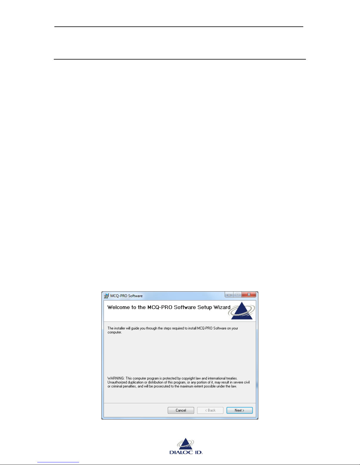
2. In Windows, open the CD-ROM drive window and run “Dialoc ID MCQ-Pro vX.X.X
Installer.msi” in “Dialoc ID MCQ-Pro” folder.
Figure 1: Setup Welcome window
Page 12
MCQ-PRO RFID Reader — Installation and Tuning Manual Version 1.00
Page 12 of 89
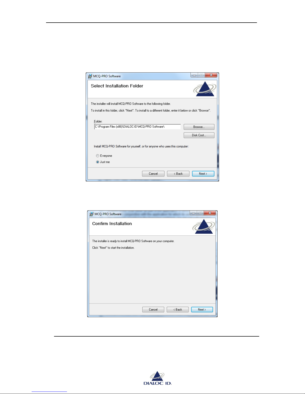
1. Click “Next >” to view terms of the license agreement, then click “Next >” again if
you agree.
Figure 2: Select Installation Folder window
2. Select the folder where MCQ-Pro software will be installed then click “Next >”.
Figure 3: Confirm Installation window
3. Click “Next >” to start the installation process. A shortcut will be created on your
desktop and a program group will be created in the start menu.
Page 13
MCQ-PRO RFID Reader — Installation and Tuning Manual Version 1.00
Page 13 of 89
3 Getting Started
This section describes how to get started using DIALOC ID MCQ-Pro software and configure
it.
Before running DIALOC ID MCQ-Pro, connect your RFID reader to the serial/USB port of
the PC or to your TCP/IP network. Connect one or more antennas to the reader.
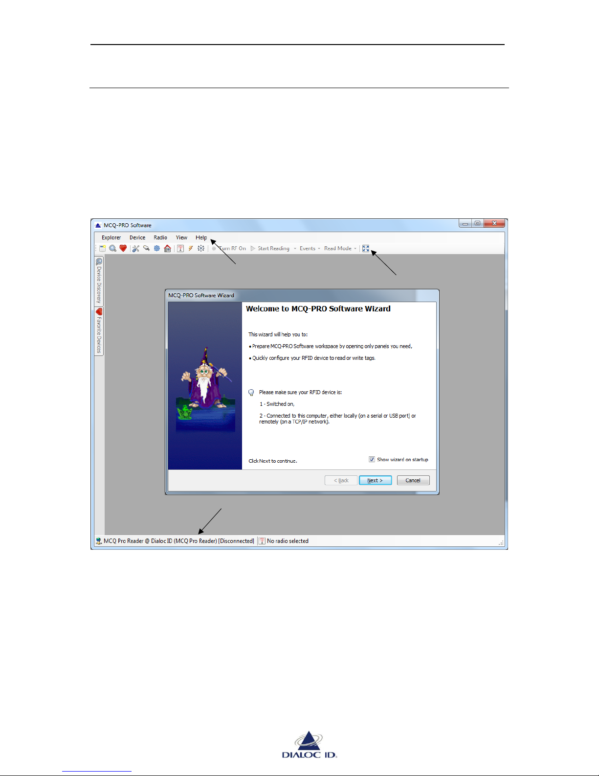
Once the reader is ready, run DIALOC ID MCQ-Pro program and the main window will be
displayed.
Figure 4: DIALOC ID MCQ-Pro window
The “DIALOC ID MCQ-Pro Wizard” opens automatically when DIALOC ID MCQ-Pro is
started for the first time.
Menu bar
Tool bar
Status bar
Page 14
MCQ-PRO RFID Reader — Installation and Tuning Manual Version 1.00
Page 14 of 89
3.1 Using DIALOC ID MCQ-Pro Wizard
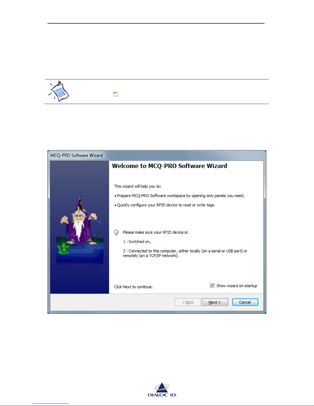
This wizard allows you to quickly set up DIALOC ID MCQ-Pro to perform basic tasks such
as configuring your RFID device and read/write operations.
If the “DIALOC ID MCQ-Pro Wizard” did not automatically open, click on the
“Wizard” icon in the toolbar or select “Wizard…” in the “MCQ-Pro” menu.
Read instructions given by the wizard and click “Next >” to continue.
Figure 5: DIALOC ID MCQ-Pro Wizard
Page 15
MCQ-PRO RFID Reader — Installation and Tuning Manual Version 1.00
Page 15 of 89
3.1.1 Selecting a Device
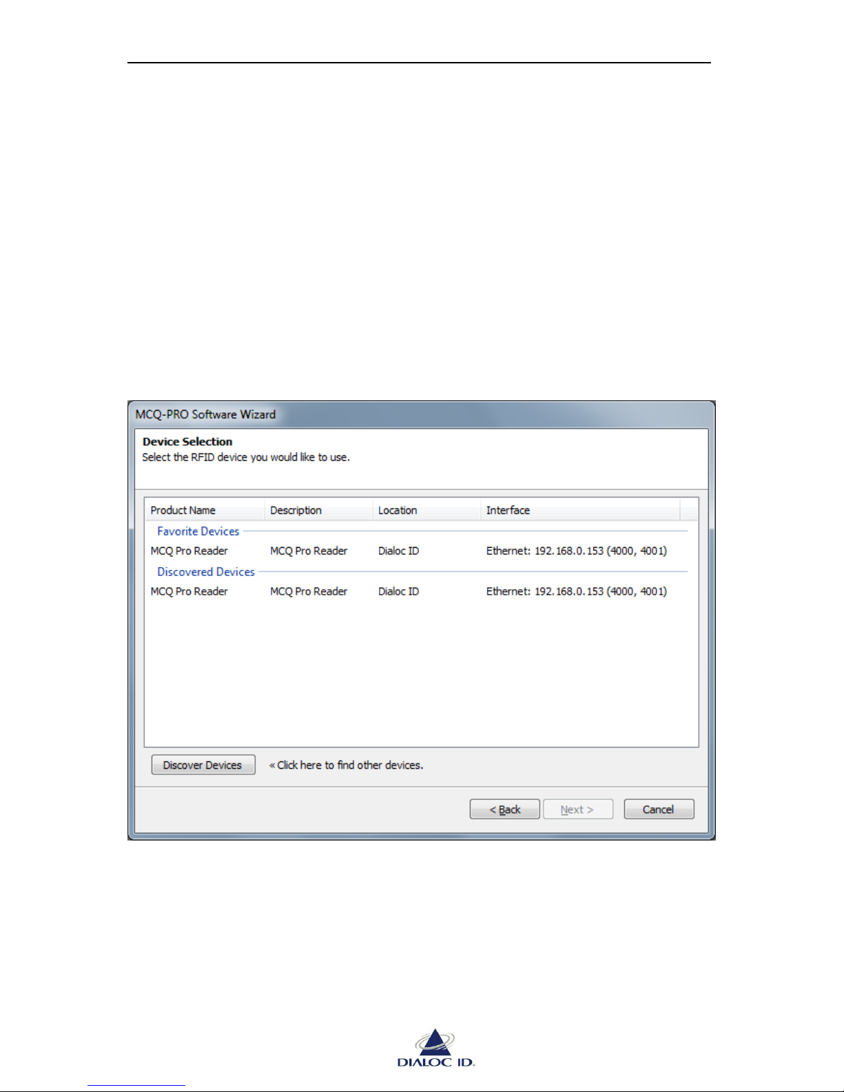
MCQ-Pro software can automatically discover and display RFID devices connected to your
computer’s serial port, USB port or connected to a TCP/IP network.
Discovered devices are displayed under “Discovered Devices” group. A same device can be
displayed one or more times depending on the number of communication interfaces
(Serial/USB, Ethernet) this device is available on. Prefer “Ethernet” interface when available
as it is the fastest communication interface.
You can refresh the “Discovered devices” at any time by clicking on “Discover Devices”.
Devices that have been already registered in MCQ-Pro software will appear under “Favorite
Devices” group. Favorite Devices are shortcuts to devices you are working often with and can
be managed using “Favorite Devices” panel. See Section 5 for more information.
Figure 6: Device Selection page
Select the device to use and click “Next >”. If necessary, this device will automatically be
added to your “Favorite Devices”.
Page 16
MCQ-PRO RFID Reader — Installation and Tuning Manual Version 1.00
Page 16 of 89
If a device with same interface details appears both in “Favorite Devices” and in
“Discovered Devices” groups, it does not matters in which group you select this
device.
3.1.2 Setting up the Device
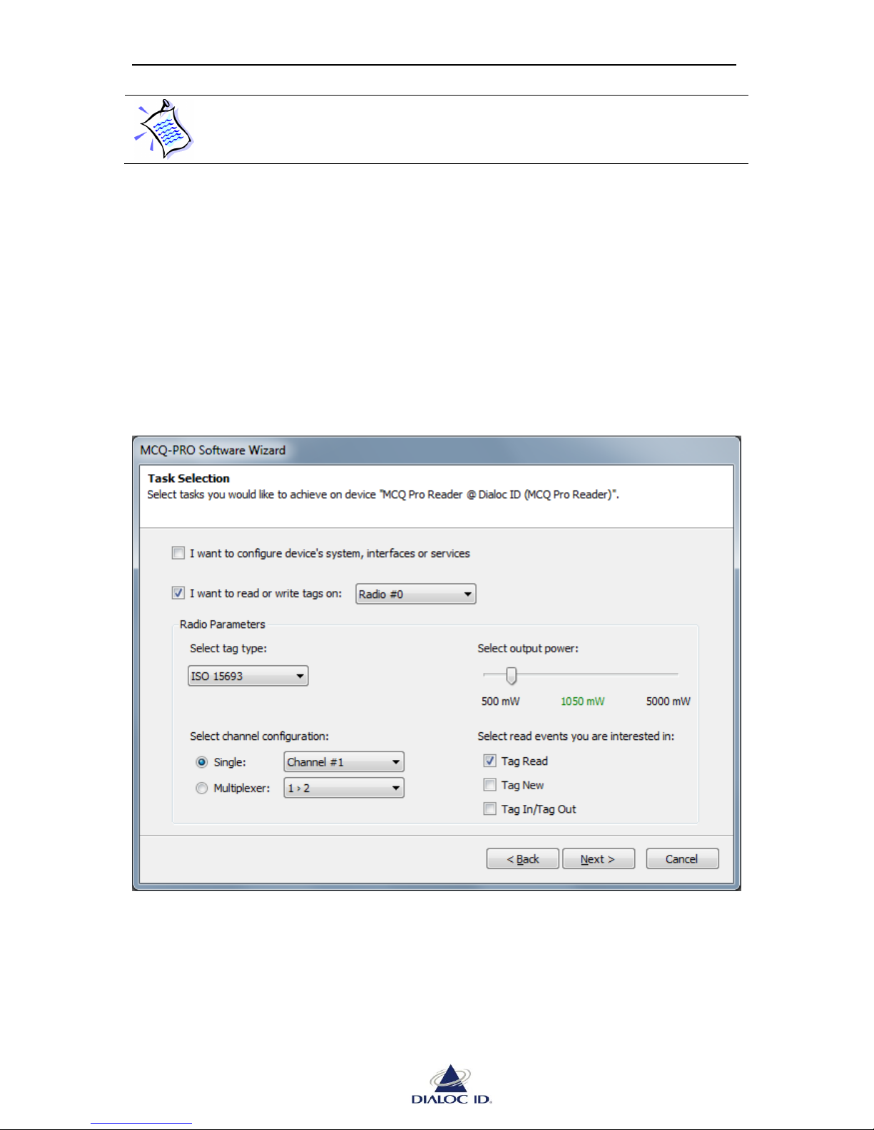
To change device’s description or communication settings, check “I want to configure
device’s system, interfaces or services”.
To perform read/write operations and send tag specific commands, check “I want to read or
write tags on”, then select the radio that should be used to perform RFID related operation.
Note that most RFID devices have only one radio.
In “Radio Parameters” section, select settings to use for radio communication.
Figure 7: Task Selection page
To test your RFID device, select the same settings as in previous figure. Then, click “Next >”.
Page 17
MCQ-PRO RFID Reader — Installation and Tuning Manual Version 1.00
Page 17 of 89
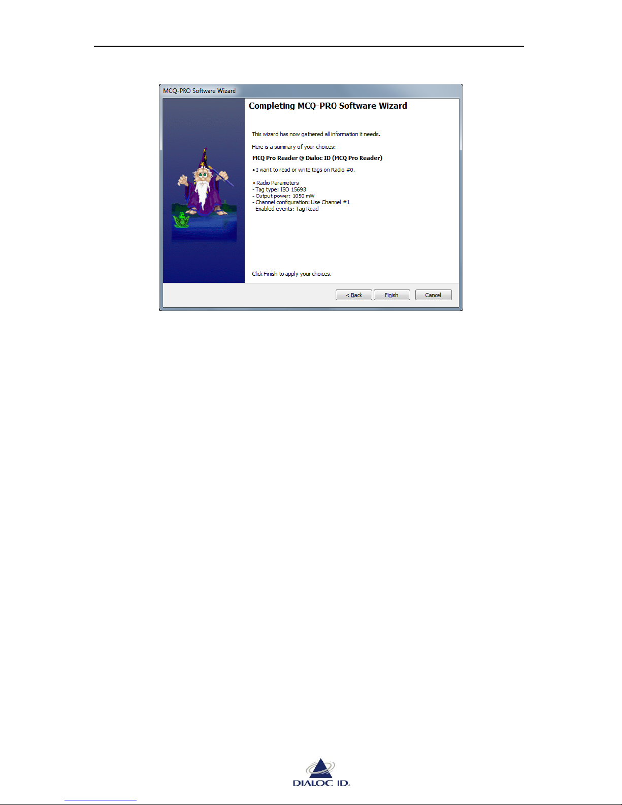
Figure 8: Wizard Summary page
Check Wizard settings and click on “Finish” to confirm
DIALOC ID MCQ-Pro software will automatically open panels you need and set the radio
configuration.
Page 18
MCQ-PRO RFID Reader — Installation and Tuning Manual Version 1.00
Page 18 of 89
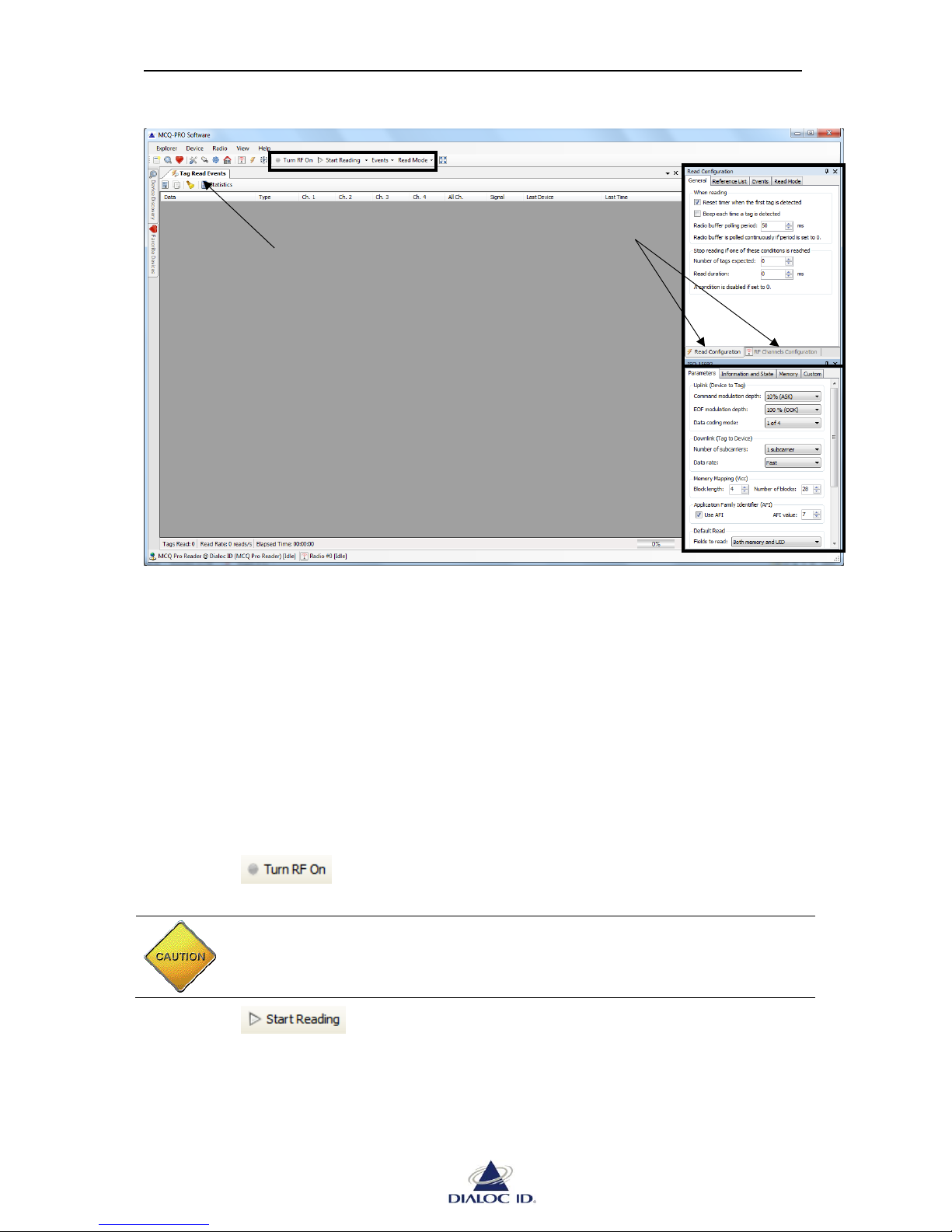
Figure 9: DIALOC ID MCQ-Pro workspace configured
3.2 Examples of Read/Write Operations
This following sections show two examples of read/write operations.
For each of them, make sure you have configured your device using DIALOC ID MCQ-Pro
wizard as explained in section 3.1.
3.2.1 Reading UID of ISO 15693 Tags
This section shows how to read asynchronously the UID of ISO 15693 tags (see section 8 for
more information about asynchronous read)
To start reading operation with current wizard configuration:
1. Click button in the toolbar.
CAUTION: Make sure an antenna is connected to the channel in use before
turning the radio field on; otherwise it may severely damage the device.
2. Click button in the toolbar.
RF/Reading controls
Read Events panel
Read and RF Channels
Configuration panels
ISO 15693 Tag
Parameters and
Commands
Page 19
MCQ-PRO RFID Reader — Installation and Tuning Manual Version 1.00
Page 19 of 89
If the radio field is turned off, DIALOC ID MCQ-Pro will ask you to turn it on;
click “OK” to accept. Again, make sure an antenna is connected to the channel
before accepting.
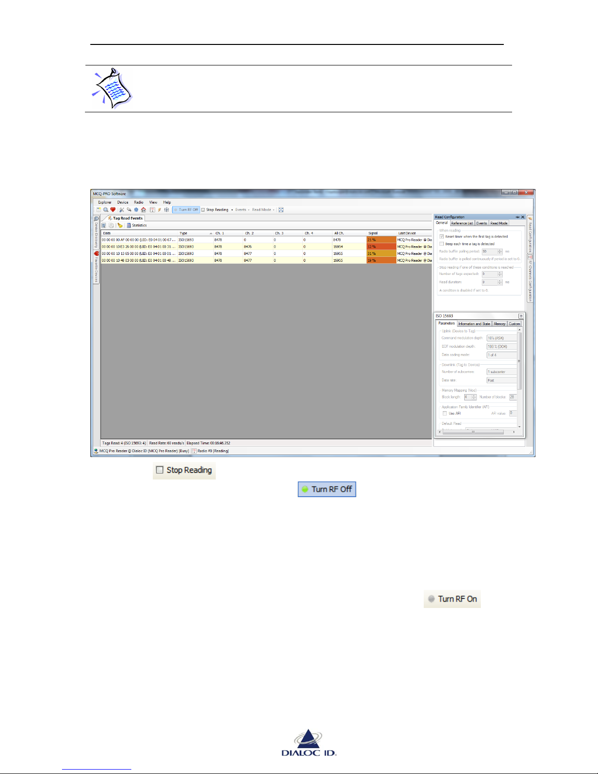
3. Place ISO 15693 tags in the radio field of channel #1 antenna.
Tags appear in the “Read Events” panel as they are read. A counter indicates how
many times they have been read on each device’s channel since read session started.
Figure 10: DIALOC ID MCQ-Pro reading ISO 15693 tags
4. Click button in the toolbar when you are finished reading. You may
turn the radio field off as well clicking button.
3.2.2 Reading or Writing ISO 15693 Tag Memory
This section shows how to send an ISO 15693 command such as a write single block
command. To send a command to a specific type of tag, use the “Tag parameters and
commands” panel with the same tag name (see section 9 for more information).
1. To send commands to tags, the radio field must be turned on. Click
button in the toolbar.
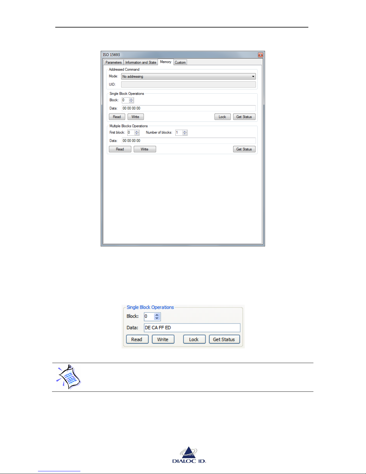
2. Click the “Memory” tab of the ISO 15693 panel that contains all memory-related
commands.
Figure 11: ISO 15693 panel (Memory tab)
Page 20
MCQ-PRO RFID Reader — Installation and Tuning Manual Version 1.00
Page 20 of 89
3. In the “Single Block Operations” box, select the block you want to write and enter its
data as hexadecimal bytes. You can pad bytes with whitespaces if you wish, but this is
not mandatory.
Figure 12: Single Block Operations
The length (in bytes) of a single block depends on the manufacturer, but most
ISO 15693 tags use four bytes blocks.
4. Place a single ISO 15693 tag in the radio field of channel #1 antenna.
Page 21

MCQ-PRO RFID Reader — Installation and Tuning Manual Version 1.00
Page 21 of 89
5. Click “Write” to write data into the memory block. If writing is successful, no error
message appears. To check block data, clear the “Data” field and click “Read” to read
data back from the block.
3.3 Configuration for AFI alarm with DiaMond RFID antennae
Select Radio → Tag Parameters and Commands→ISO15693.
In the Parameters tab select Use AFI and select the AFI value. The AFI value representation
is Hexadecimal. This is explained in §9.4.1 ISO 15693 Parameters Tab.
Select Radio → RF Channels Configuration
In the Multiplexer tab push + Add, select tag type ISO15693, set to power slider to the power
for this antenna (3000mW) and select the both Emitter and Receiver for the channel the
antenna is on. Repeat the +Add procedure for all antennae on this controller and then push the
Apply button. This is explained in §7.1.2 Multiplexer Configuration.
In the Read Mode drop down box select Enable Multiplexer and Enable Output Feedback.
This is explained in §8.2.4 Read Mode.
In the Events drop down box select Read Tag, deselect all other settings in this box. This is
explained in §8.2.3 Events.
Save the configuration in memory, see Saving Radio Configuration to NVRAM on page 33.
Select Device → Standalone Mode Configuration. Click the Enable Standalone Mode button.
See §11.2 Enabling standalone mode.
The unit is now functioning in the AFI alarm mode.
Page 22
MCQ-PRO RFID Reader — Installation and Tuning Manual Version 1.00
Page 22 of 89
4 DIALOC ID MCQ-Pro’s Workspace
4.1 Workspace Panel Arrangement
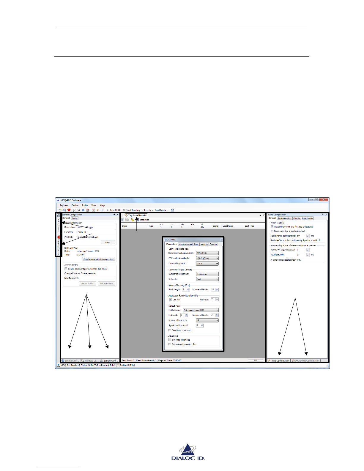
DIALOC ID MCQ-Pro’s workspace consists of several regions where you can drag and drop
panels in your preferred layout.
You have many options for arranging panels within the workspace, including the following:
Tab-dock, tile or make central or lateral panels float.
Minimize lateral panels as vertical tabs.
Reset panel placement to the default layout.
The figure below illustrates different ways to position the panels.
Figure 13: DIALOC ID MCQ-Pro’s workspace
4.1.1 Moving panels
To undock a docked panel, left-click on its tab, pull it out of its current location and release
the mouse button. When a panel is undocked, it floats in its own window on top of the other
panels.
Three panels
docked on left
side
One panel
floating in a
window
One panel docked
on center
Two panels
docked on
right side
Panels
hidden
as tabs
Page 23
MCQ-PRO RFID Reader — Installation and Tuning Manual Version 1.00
Page 23 of 89
To dock a floating panel, left-click on the title bar of its window and drag it to the location
where you want to dock it.
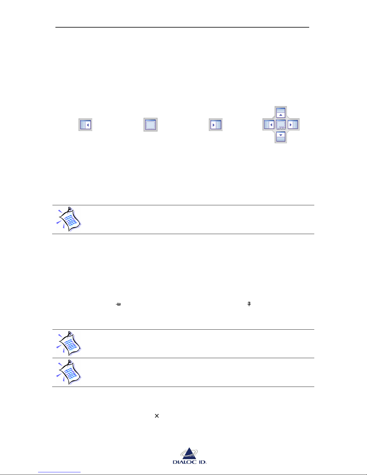
A floating panel can be fastened to one edge of a frame within the workspace. A guide
diamond appears when you drag panels from their current location to another location in the
workspace. The guide diamond allows you to quickly re-dock a panel on one of the left,
middle or right locations of the workspace.
Dock on left location
Dock on middle
location
Dock on right
location
Multiple locations
possible
When you point the guide diamond, an outline of the panel appears in the designated area. To
dock the panel in the position indicated, release the mouse button.
To move an undocked panel without snapping it into place, press CTRL while
dragging it.
4.1.2 Minimizing panels
Lateral panels, which can be docked on left and right edges of the workspace, support a
feature called Auto Hide. Auto Hide enables to show only panels you need at one time by
minimizing other panels along the edges of the workspace when not in use.
Auto Hide enabled
Auto Hide disabled
Panels that have Auto Hide enabled temporarily slide into view when the panel
has focus. To hide the panel again, click outside of the current panel. Once the
panel loses focus, it slides back out of view.
Panels cannot be moved while Auto Hide is enabled. Disable Auto Hide first to
dock the panel somewhere else or to make it float.
4.1.3 Closing panels
To close a panel, click on the icon “ “in its title bar; or select it clicking its title bar and
choose “Close Panel” in the “MCQ-Pro” menu.
Page 24

MCQ-PRO RFID Reader — Installation and Tuning Manual Version 1.00
Page 24 of 89
4.1.4 Restoring default panel layout
You can return the workspace to the original panel layout by choosing “Restore Default Panel
Layout…” in the “View” menu.
4.1.5 Switching workspace to full screen
You can switch the workspace to full screen by clicking on the “Full screen” icon in the
toolbar or by choosing “Full Screen” in the “View” menu. Follow the same steps to exit full
screen.
Page 25
MCQ-PRO RFID Reader — Installation and Tuning Manual Version 1.00
Page 25 of 89
5 Managing your RFID devices
5.1 How to Manage your Favorite Devices
RFID devices you are working often with are called favorite devices in DIALOC ID MCQPro software. You can manage favorite devices using “Favorite Devices” panel.
To open “Favorite Devices” panel, click on the icon in the toolbar or select “Favorite
Devices” in the “Device” menu.
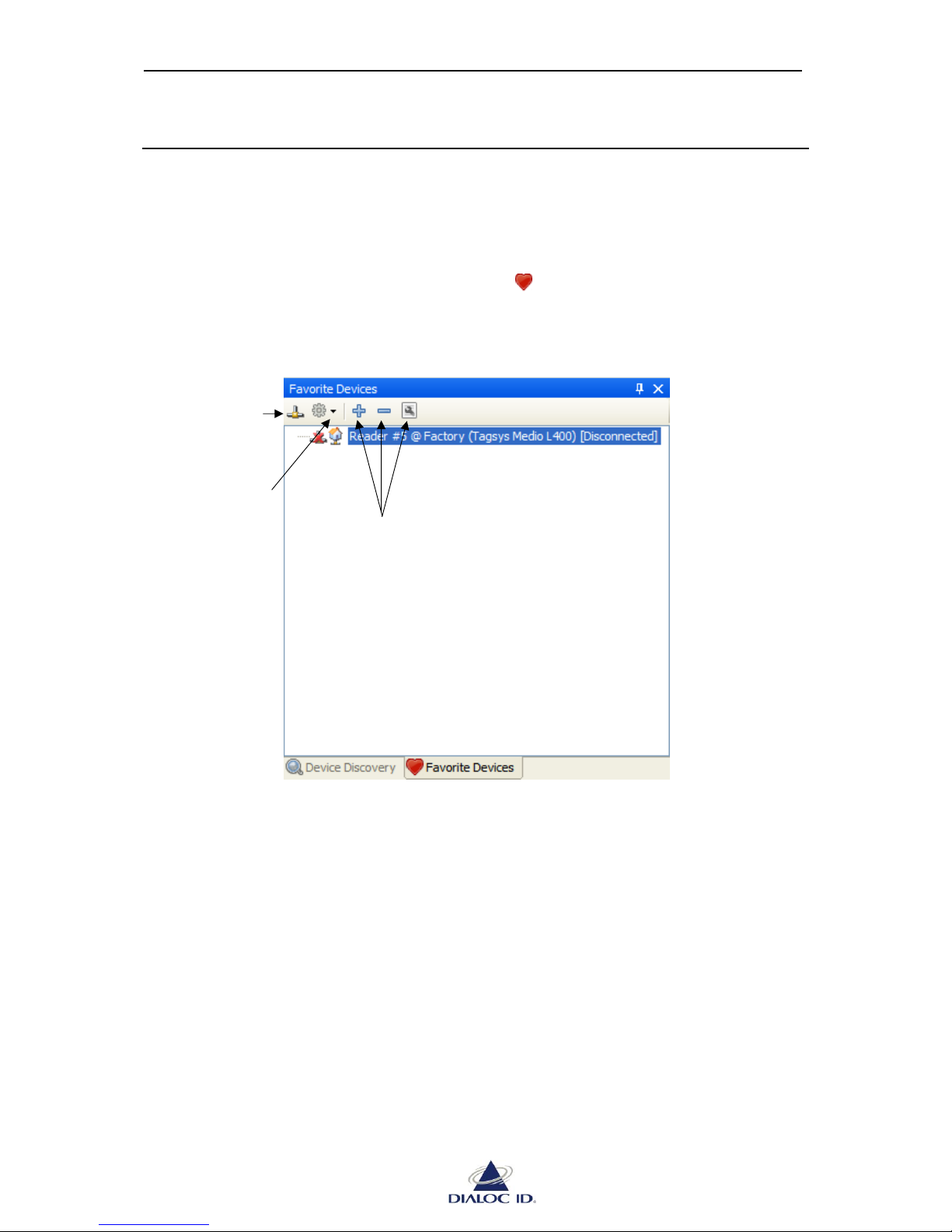
Figure 14: Favorite Devices panel
Registering a new Favorite Device can either be done manually or using Device Discovery.
5.1.1 Adding a Favorite Device Using Device Discovery
DIALOC ID MCQ-Pro can automatically discover RFID devices plugged into your
computer’s serial port, USB port or connected to a TCP/IP network.
Connect to or
Disconnect from
selected device
Perform special
actions with
selected device
Add / Remove / Edit a
favorite device
Page 26
MCQ-PRO RFID Reader — Installation and Tuning Manual Version 1.00
Page 26 of 89
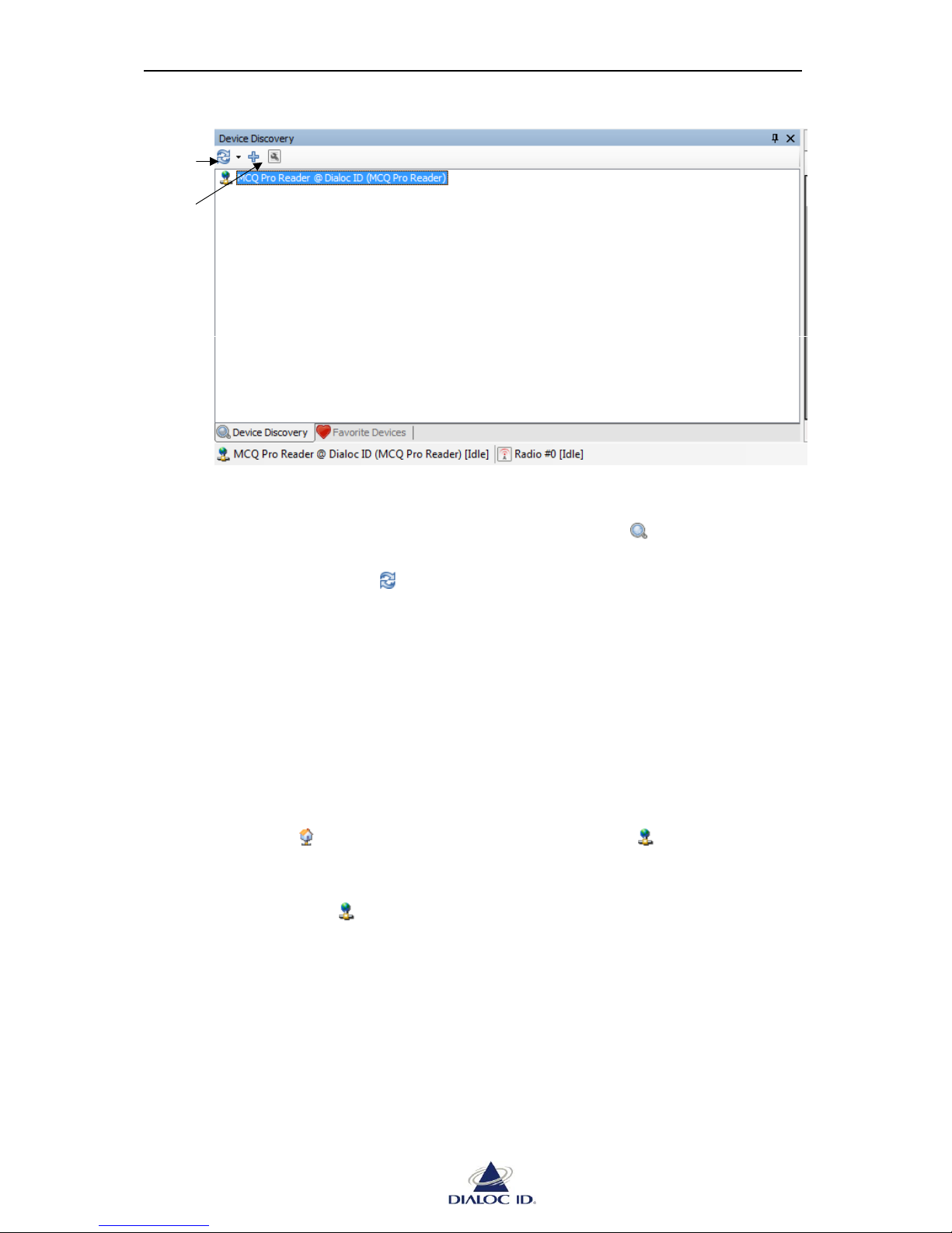
Figure 15: Device Discovery panel
To discover devices:
1. Open “Device Discovery” panel by clicking on the icon in the toolbar or by
choosing “Device Discovery” in the “Device” menu.
2. Use the drop down menu to start device discovery.
Choose “Discover Local Devices” to discover devices plugged into your computer’s
serial or USB ports.
Choose “Discover Remote Devices” to discover devices connected on a TCP/IP
network.
Choose “Discover All Devices” to discover both kind of devices.
3. Devices are listed. Point out the mouse cursor to the device to get its information.
A same device can be displayed one or more times depending on the number of
communication interfaces (Serial/USB, Ethernet) this device is available on. The icon close to
the device’s name shows the type of communication interface available.
Serial/USB interface
Ethernet (TCP/IP) interface
Prefer “Ethernet” interface when available as it is the fastest communication interface.
To use a device, you must add it to favorites:
1. Select the discovered device to add to favorites.
Discover local and
remote devices
Add selected device
to favorites
Page 27
MCQ-PRO RFID Reader — Installation and Tuning Manual Version 1.00
Page 27 of 89
2. Click the icon to add this device to favorites.
Alternatively, you may as well double-click the device or right-click the device and
choose “Add to Favorite Devices”.
If you are already connected to a device plugged into your computer’s serial or
USB ports, it will not appear during device discovery until you disconnect from
it. This is a normal behavior.
If a firewall is active on your computer, you should authorize incoming UDP
packets on port 4002 to allow device discovery.
With Windows Firewall, this can be performed on control panel’s “Exceptions”
tab.
To ensure discovered TCP/IP devices can be connected to, Dialoc ID MCQ-Pro
automatically pings them. If “[Unreachable]” is displayed next to a device in
“Device Discovery” panel, this means that pinging this device has failed and you
may not be able to connect to it using its Ethernet interface. This is usually
because device and computer network addresses do not match. Try changing the
TCP/IP configuration of your computer or of the device.
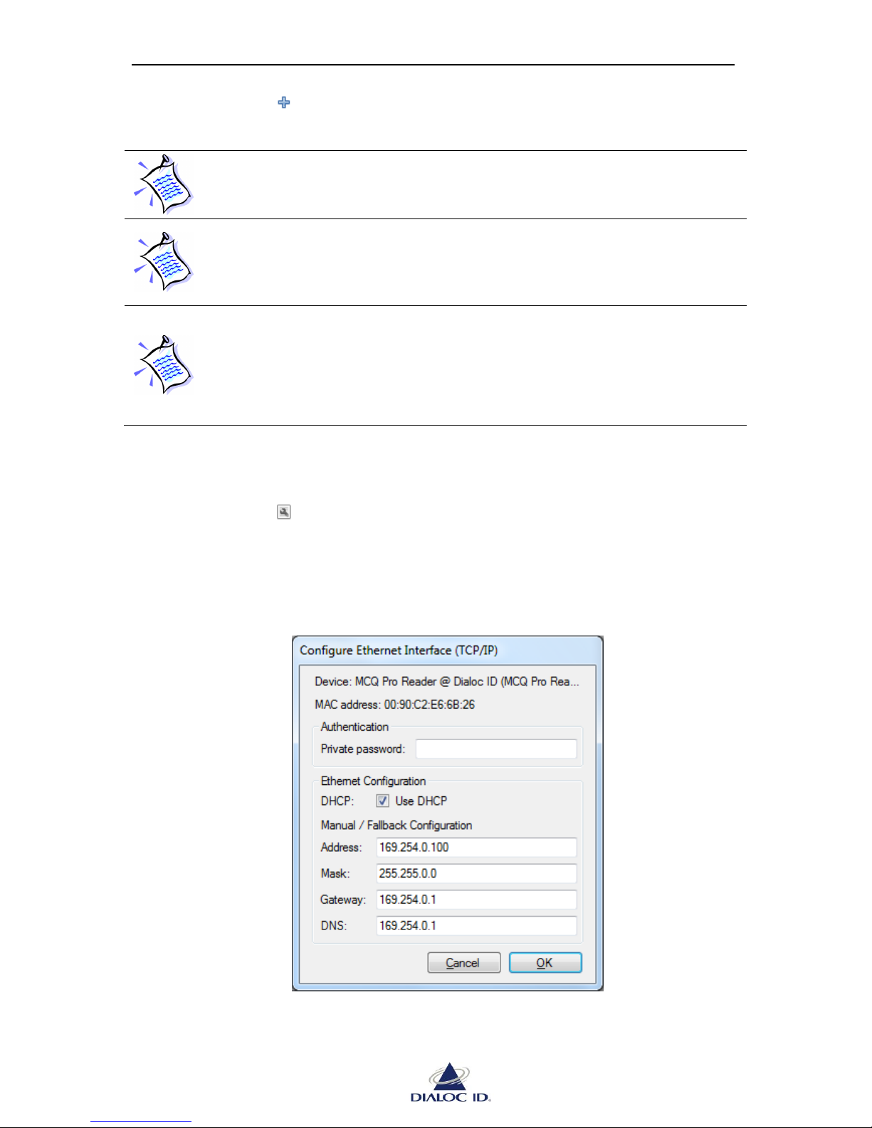
To change the TCP/IP configuration of a discovered Ethernet device that is unreachable:
1. Select the unreachable device.
2. Click the icon to configure its Ethernet interface.
Alternatively, you may as well right-click the device and choose “Configure Ethernet
Interface (TCP/IP)”.
Figure 16: Configure Ethernet Interface (TCP/IP)
Page 28
MCQ-PRO RFID Reader — Installation and Tuning Manual Version 1.00
Page 28 of 89
3. If device’s access control is enabled, enter private password in “Private password”
field, else leave the field blank. If a wrong password is entered, request for
configuration change is ignored
4. Set the TCP/IP configuration and click OK twice to confirm changes. Device will
automatically reboot and use the new TCP/IP configuration.
5. Once the device has rebooted, restart a device discovery operation by using the drop
down menu .
Alternatively, you can see section 6.2.3 for more information about configuring TCP/IP
interface once connected to a device.
5.1.2 Manually Adding or Editing a Favorite Device
To add a device to favorites:
1. Open “Favorite Devices” panel by clicking on the icon in the toolbar or by
choosing “Favorite Devices” in the “Device” menu.
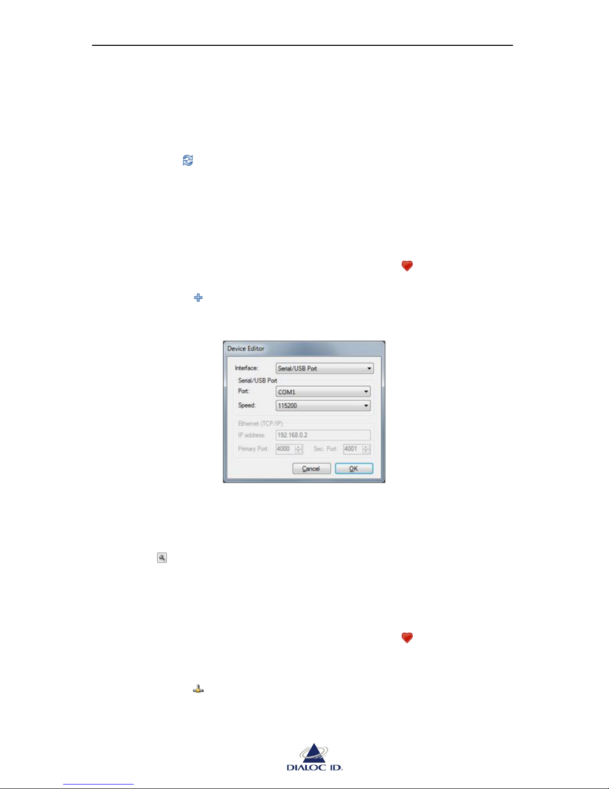
2. Click the icon to add a new favorite device. This will open the “Device Editor”.
Figure 17: Device Editor
3. Select the type of interface to use in the “Interface” combo box.
4. Fill in interface information in the following fields.
5. Click OK to add the device to favorites.
To edit a favorite device and change its interface information, perform the same steps but
click the icon or right-click the device and choose “Edit Device”.
5.1.3 Connecting, Disconnecting and Rebooting a Device
To connect to a device:
1. Open “Favorite Devices” panel by clicking on the icon in the toolbar or by
choosing “Favorite Devices” in the “Device” menu.
2. Select the device.
3. Click the icon to connect to it.
Alternatively, you may as well double-click the device or right-click the device and
select “Connect to Device”.
Page 29
MCQ-PRO RFID Reader — Installation and Tuning Manual Version 1.00
Page 29 of 89
To disconnect from a device, perform the same steps but click on the icon or right-click
the device and select “Disconnect from Device”.
To reboot a device, perform the same steps but click on the icon or right-click the device
and select “Reboot Device”.
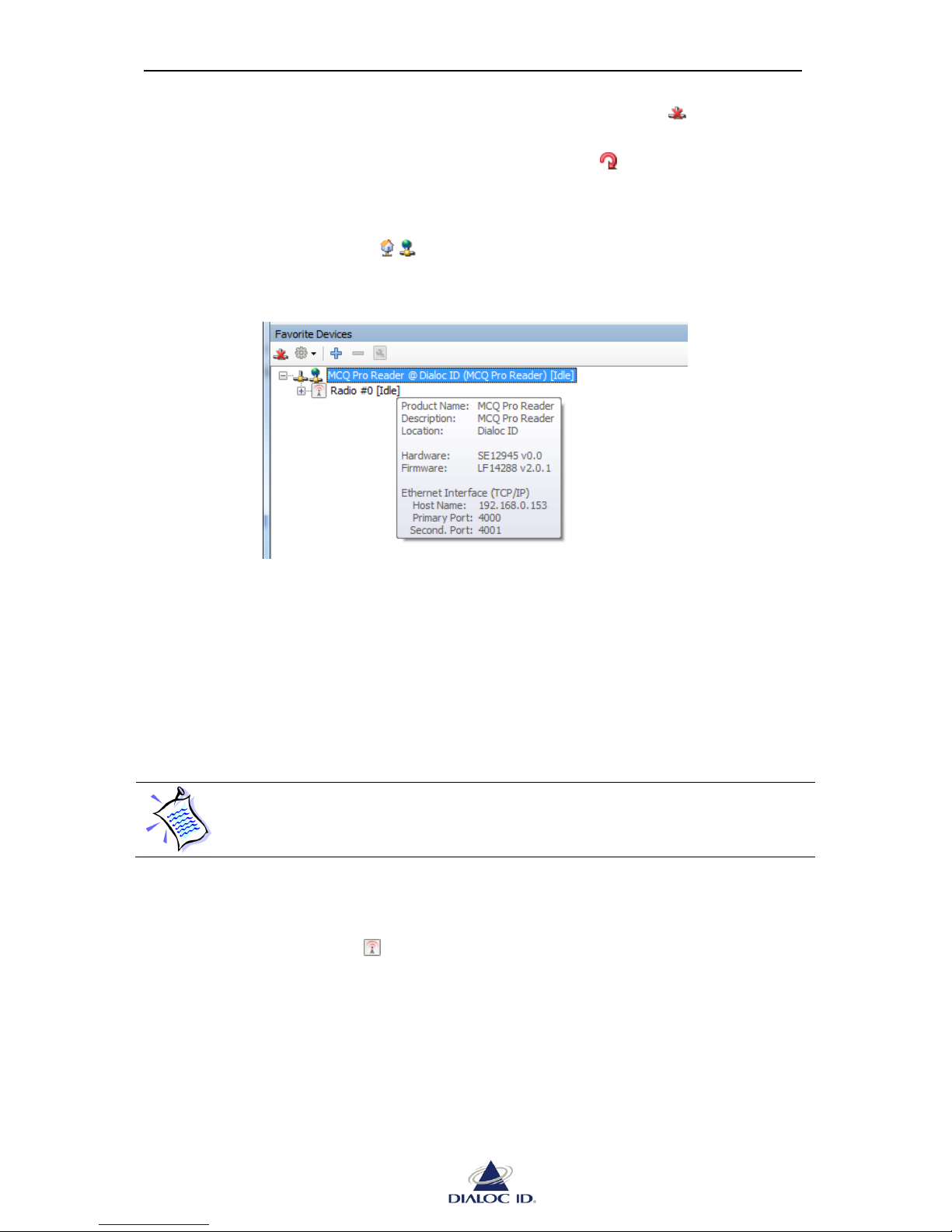
5.1.4 Getting Device Information
You can point out a device icon ( ) to get its information.
Figure 18: Device Information
Product Name: DIALOC ID RFID device product name.
Description and Location: give custom information set for this device. They can be set in
“System Configuration” panel; see section 6.1 for more information.
Hardware and Firmware: give hardware and firmware version.
Serial Interface or Ethernet Interface: These sections give connection information
currently used to connect to the device.
If you swap a device plugged into your computer’s serial or USB ports with
another device, information about the device will be refreshed only when
connecting to it.
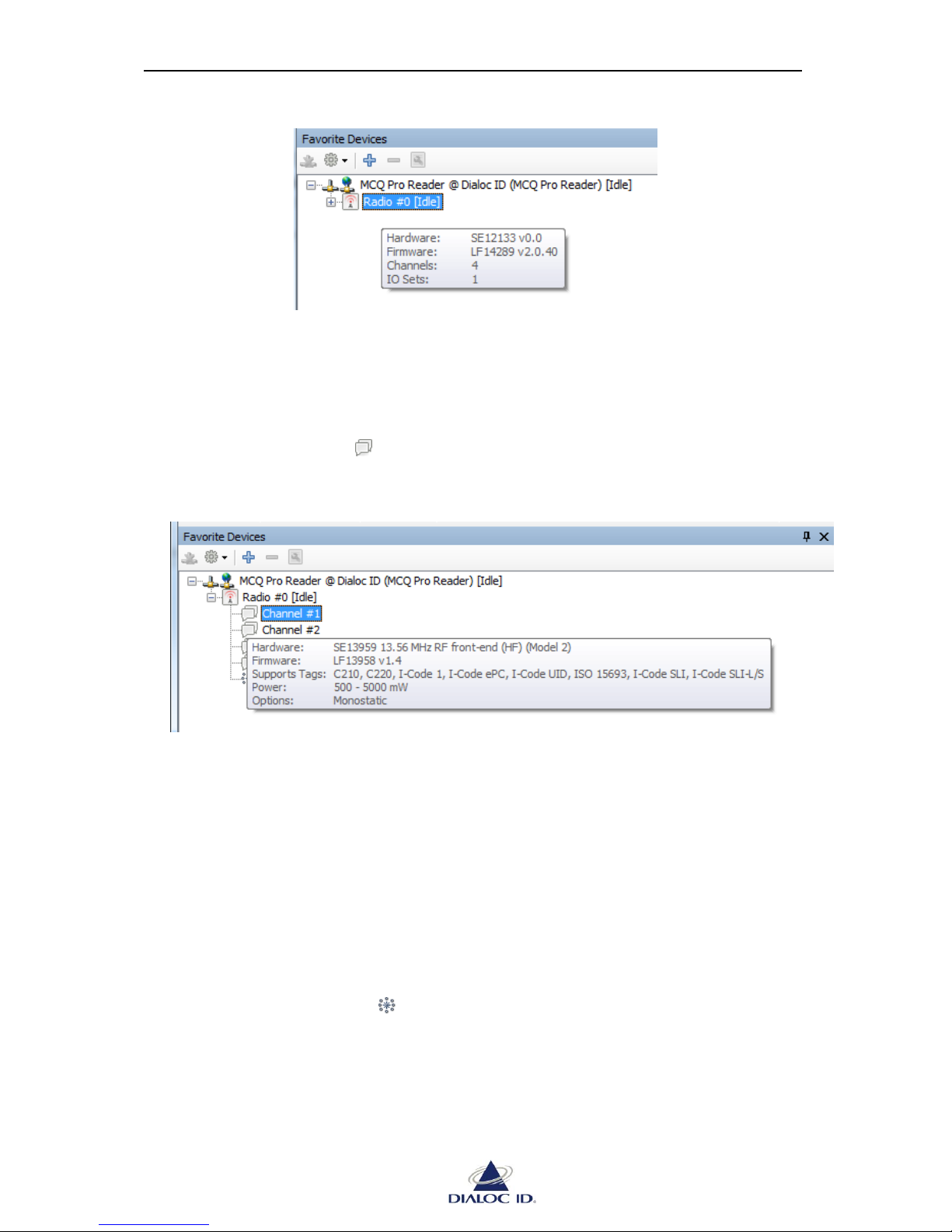
Getting Radio Information
You can point out a radio icon to get its information.
Page 30
MCQ-PRO RFID Reader — Installation and Tuning Manual Version 1.00
Page 30 of 89
Figure 19: Radio Information
Hardware and Firmware: give hardware and firmware version.
Channels and IO Sets: indicates number of RF channel and IO sets.
Getting Channel Information
You can point a channel icon to get information about it.
Figure 20: Information about a channel
Hardware and Firmware: gives hardware and firmware version.
Supports Tags: indicates tags supported by the channel.
Power: indicates minimum and maximum power supported by the channel.
Options: indicates special characteristics of the channel such as:
Supports +π Phase Shifting indicates the RF field phase can be shifted by +π.
Monostatic indicates that the channel can be configured as an emitter only or
as both an emitter and a receiver.
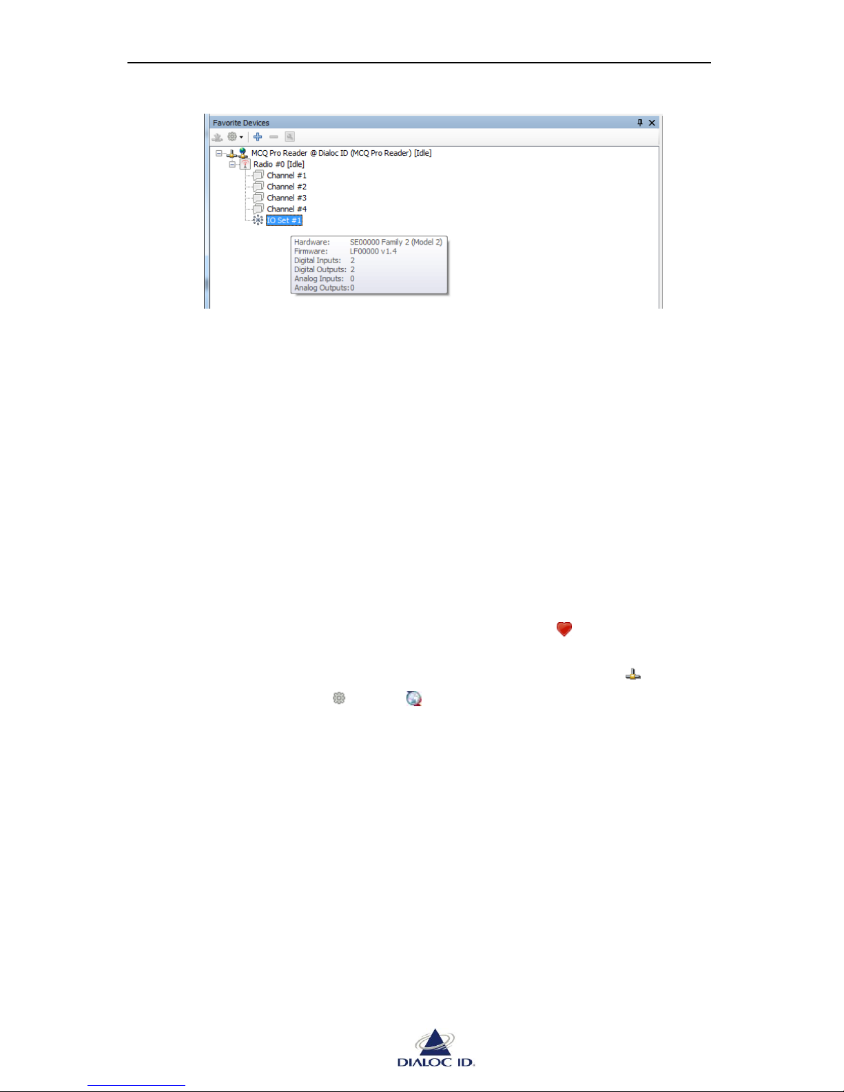
Getting IO set Information
You can point out an IO set icon to get its information.
Page 31
MCQ-PRO RFID Reader — Installation and Tuning Manual Version 1.00
Page 31 of 89
Figure 21: Information about an IO set
Hardware and Firmware: gives version information about IO set’s hardware and firmware.
Digital Inputs, Digital Outputs, Analog Inputs and Analog Outputs: indicates the number
of digital/analog inputs and outputs of the IO sets.
5.1.5 Upgrading Firmwares
Two different kind of firmware can be upgraded in your RFID device:
System firmware which manages protocols and interfaces for communication with the
host,
Radio firmware which manages RFID operations.
System Firmware Upgrade
To upgrade system firmware:
1. Open “Favorite Devices” panel by clicking on the icon in the toolbar or by
choosing “Favorite Devices” in the “Device” menu.
2. Connect to the device to upgrade by selecting it and clicking on the icon .
3. In the drop down menu , select “ Upgrade System Firmware…”. Alternatively,
you may as well right-click the device.
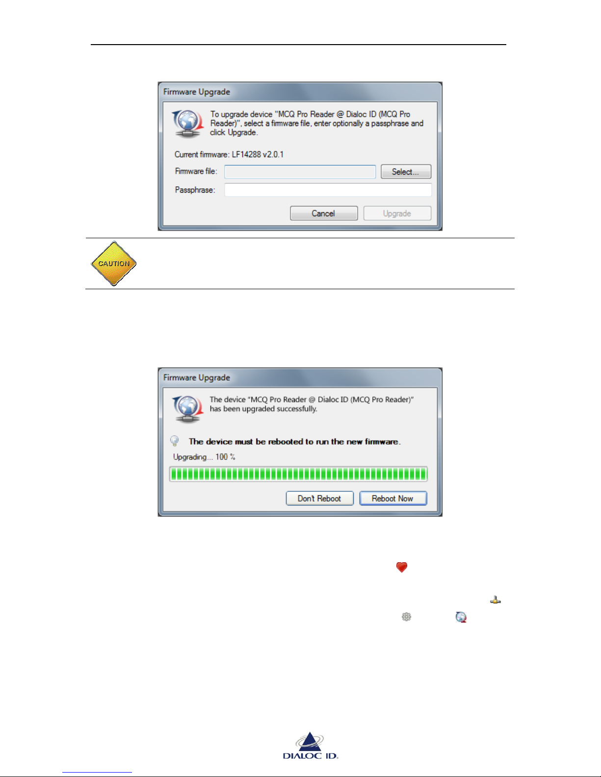
4. In the “Firmware Upgrade” dialog box, select the firmware file, enter if necessary its
associated passphrase and click “Upgrade”.
Page 32
MCQ-PRO RFID Reader — Installation and Tuning Manual Version 1.00
Page 32 of 89
Figure 22: System firmware upgrade
CAUTION: Do not turn off the device during the upgrade as this may
permanently corrupt the firmware data.
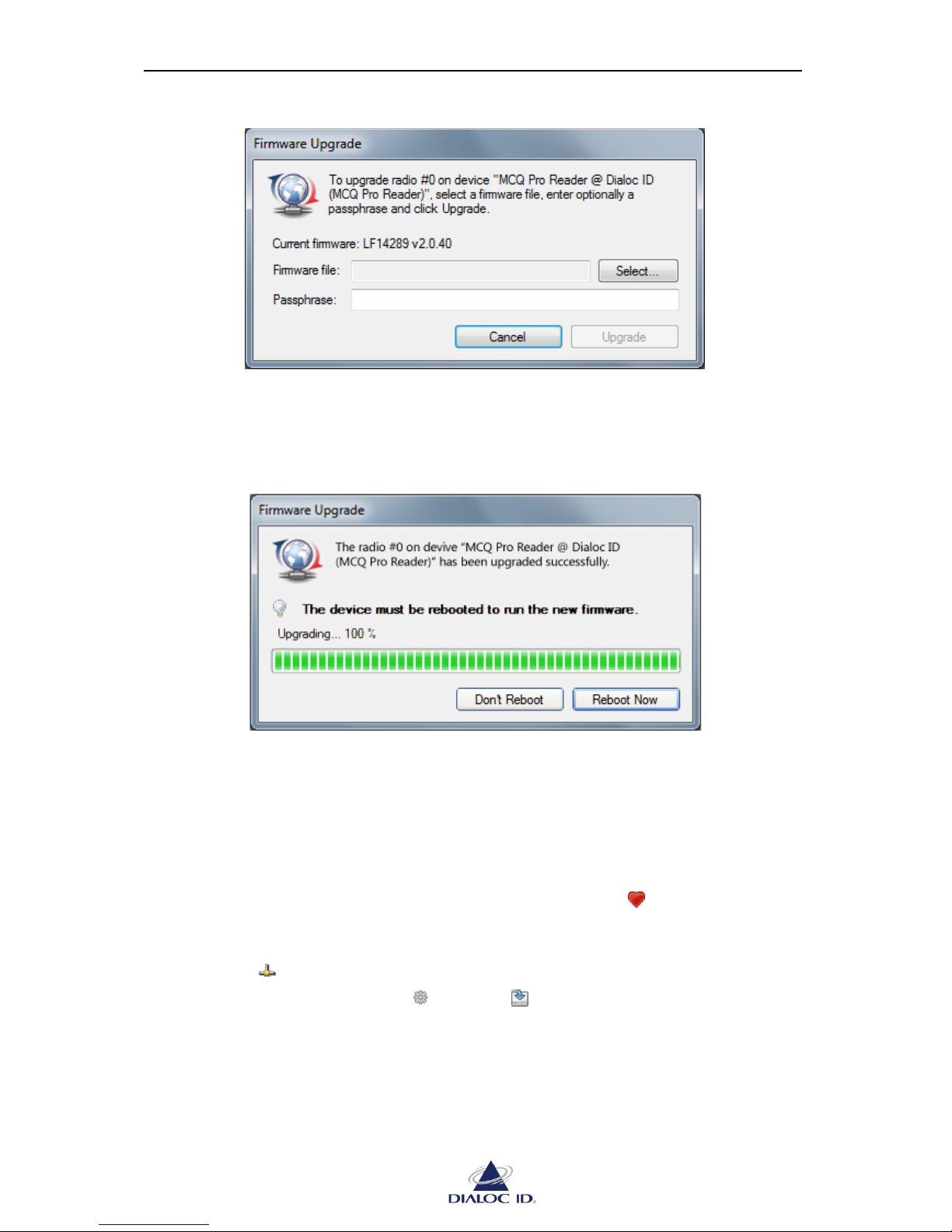
5. Once the upgrade is completed, click “Reboot”.
If you need to upgrade additional firmware to the device then click “Don’t Reboot”.
Figure 23: System firmware upgrade completed
Radio Firmware Upgrade
To upgrade radio firmware:
1. Open “Favorite Devices” panel by clicking on the icon in the toolbar or by
choosing “Favorite Devices” in the “Device” menu.
2. Connect to the device to upgrade the radio by selecting it and clicking on the icon .
3. Click on the radio to upgrade and in the drop down menu , select “ Upgrade
Radio Firmware…” Alternatively, you may as well right-click the radio.
4. In the “Firmware Upgrade” dialog box, select the firmware file, enter if necessary its
associated passphrase and click “Upgrade”.
Page 33
MCQ-PRO RFID Reader — Installation and Tuning Manual Version 1.00
Page 33 of 89
Figure 24: Radio firmware upgrade
6. Once the upgrade is completed, click “Reboot”.
If you need to upgrade additional firmware to the device first then click “Don’t
Reboot”.
Figure 25: Radio firmware upgrade completed
5.1.6 Managing Default Radio Configuration
Default radio configuration is loaded from internal non-volatile memory (NVRAM) when
device is powered on.
Saving Radio Configuration to NVRAM
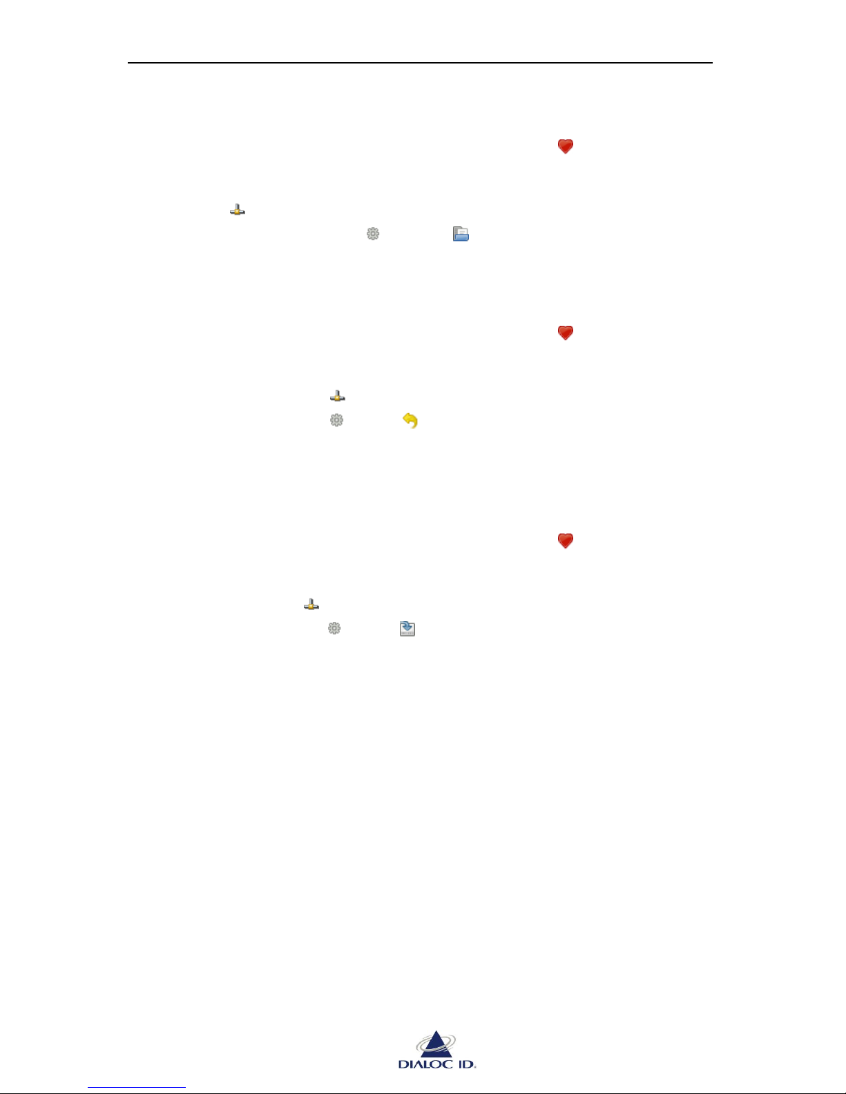
To make your radio configuration persistent, you must save it to NVRAM:
1. Open “Favorite Devices” panel by clicking on the icon in the toolbar or by
choosing “Favorite Devices” in the “Device” menu.
2. Connect to the device to save the radio configuration by selecting it and clicking on
the icon .
3. In the drop down menu , select “ Save Configuration to NVRAM”.
Alternatively, you may as well right-click the device.
Page 34
MCQ-PRO RFID Reader — Installation and Tuning Manual Version 1.00
Page 34 of 89
Loading Radio Configuration from NVRAM
To load radio configuration from NVRAM:
1. Open “Favorite Devices” panel by clicking on the icon in the toolbar or by
choosing “Favorite Devices” in the “Device” menu.
2. Connect to the device to load the radio configuration by selecting it and clicking on
the icon .
3. In the drop down menu , select “ Load Configuration to NVRAM”.
Alternatively, you may as well right-click the device.
Restoring Radio Configuration to Default Factory Settings
To reset radio configuration to factory settings:
1. Open “Favorite Devices” panel by clicking on the icon in the toolbar or by
choosing “Favorite Devices” in the “Device” menu.
2. Connect to the device that you want to restore the radio configuration by selecting it
and clicking on the icon .
3. In the drop down menu , select “ Restore Factory Configuration”. Alternatively,
you may as well right-click the device.
5.1.7 Saving/Loading Device Configuration to/from Disk
To save device configuration to disk:
1. Open “Favorite Devices” panel by clicking on the icon in the toolbar or by
choosing “Favorite Devices” in the “Device” menu.
2. Connect to the device that you want to save the configuration by selecting it and
clicking on the icon .
3. In the drop down menu , select “ Save Configuration…”. Alternatively, you may
as well right-click the device.
Page 35
MCQ-PRO RFID Reader — Installation and Tuning Manual Version 1.00
Page 35 of 89
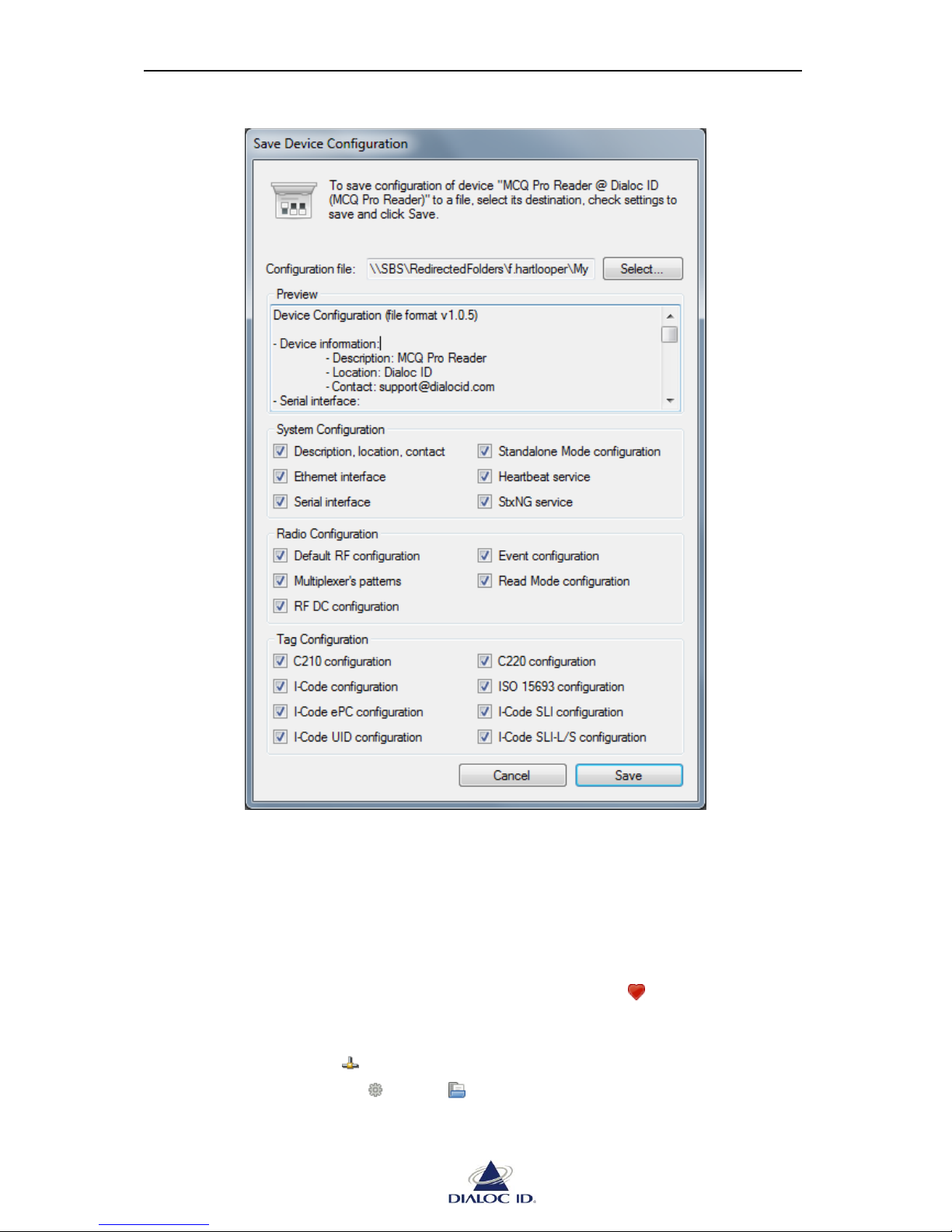
Figure 26: Save Device Configuration dialog
4. Click “Select…” button to choose location of configuration file.
5. Check device settings to save and click “Save” to save the configuration file.
To load device configuration from disk:
1. Open “Favorite Devices” panel by clicking on the icon in the toolbar or by
choosing “Favorite Devices” in the “Device” menu.
2. Connect to the device that you want to load the configuration by selecting it and
clicking on the icon .
3. In the drop down menu , select “ Load Configuration…”. Alternatively, you may
as well right-click the device.
Page 36
MCQ-PRO RFID Reader — Installation and Tuning Manual Version 1.00
Page 36 of 89
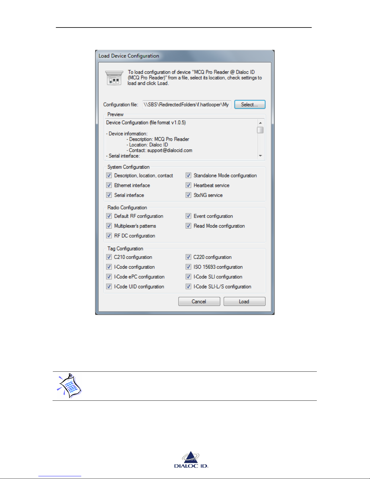
Figure 27: Load Device Configuration dialog
4. Click “Select…” button to choose location of configuration file.
5. Check device settings to load and click “Load” to save the configuration file.
Settings that were not saved in a configuration file are displayed as disabled.
Page 37
MCQ-PRO RFID Reader — Installation and Tuning Manual Version 1.00
Page 37 of 89
6 Core Configuration
6.1 System Configuration
Open “System Configuration” panel by clicking on the icon in the toolbar or by choosing
“System Configuration” in the “Device” menu.
6.1.1 General Tab
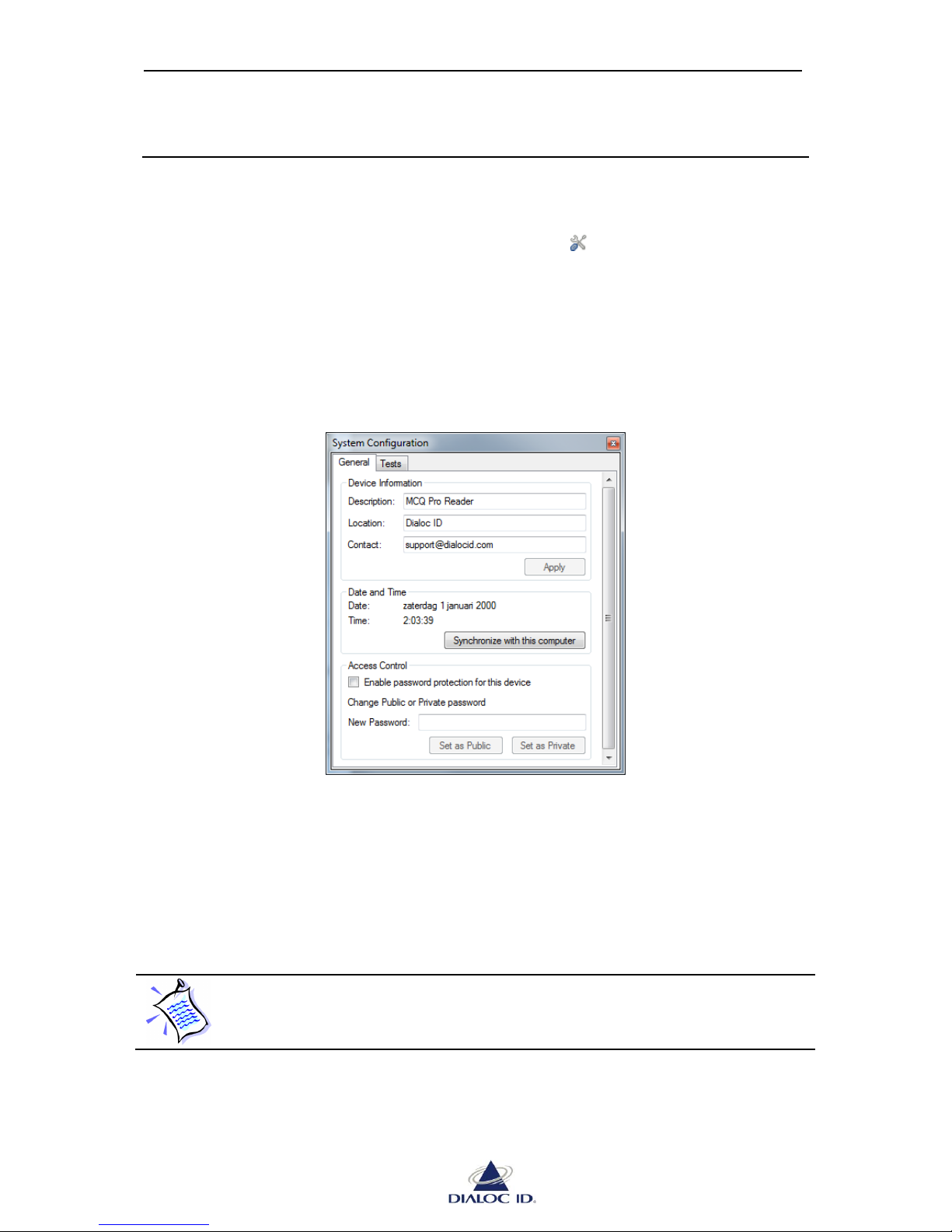
You can configure general system settings on “General” tab.
Figure 28: System Configuration panel (General tab)
Device Information: You can view and modify device’s description, location and contact
information in this box. Click “Apply” to apply your changes.
Date and Time: You can set device’s clock by clicking “Synchronize with this computer”
button.
The date/time configuration is not battery-backed on the MCQ-Pro Reader.
Page 38
MCQ-PRO RFID Reader — Installation and Tuning Manual Version 1.00
Page 38 of 89
Access Control: You can enable password protection for the device and choose public and
private passwords if your application requires it. You must reboot the device after having
changed password protection status (see section 5.1.3).
When logged into a protected device using public password no settings can be changed. If
logged into the device using private password then changes are permitted.
DIALOC ID MCQ-Pro requires to log into protected devices using private password.
Default public password is “public” and default private password is “private”
(both without quotes). If you forget private password, you must hard reset
device’s non-volatile memory. See device User’s Guide for more information.
6.1.2 Tests Tab
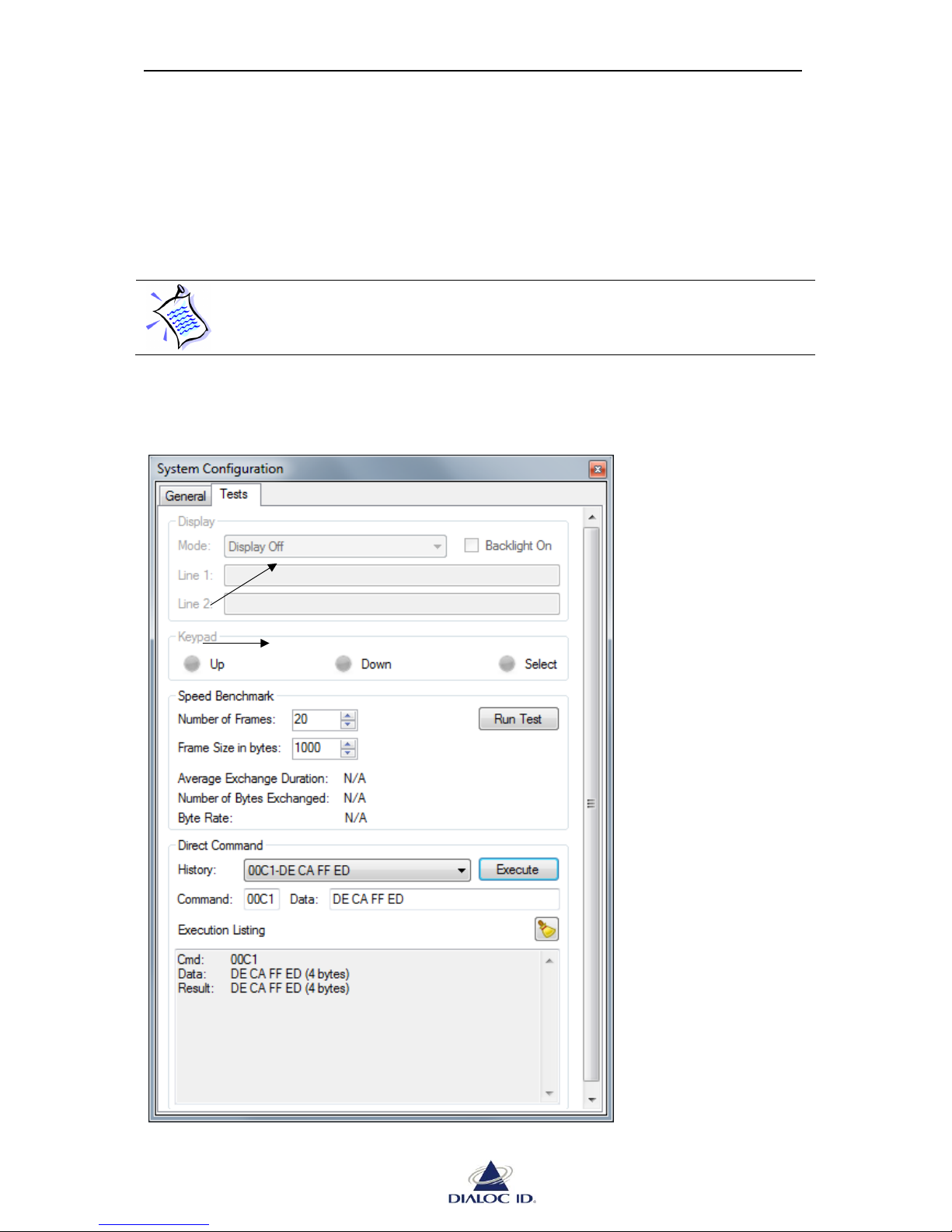
You can test operation of the device on “Tests” tab.
Figure 29: System Configuration panel (Tests tab)
Not applicable with
this device
Page 39
MCQ-PRO RFID Reader — Installation and Tuning Manual Version 1.00
Page 39 of 89
Speed Benchmark: You can benchmark communication speed with device by clicking “Run
test” button.
Direct Command: You can send any command directly to a device by entering its identifier in
“Command” field and its associated data in “Data” field (both as hexadecimal values) and
clicking “Execute”. Recent commands are displayed in “History” list.
See Designer’s Guide for more information about supported commands.
6.2 Communication Interfaces Configuration
Open “Interface Configuration” panel by clicking on the icon in the toolbar or by choosing
“Interface Configuration” in the “Device” menu.
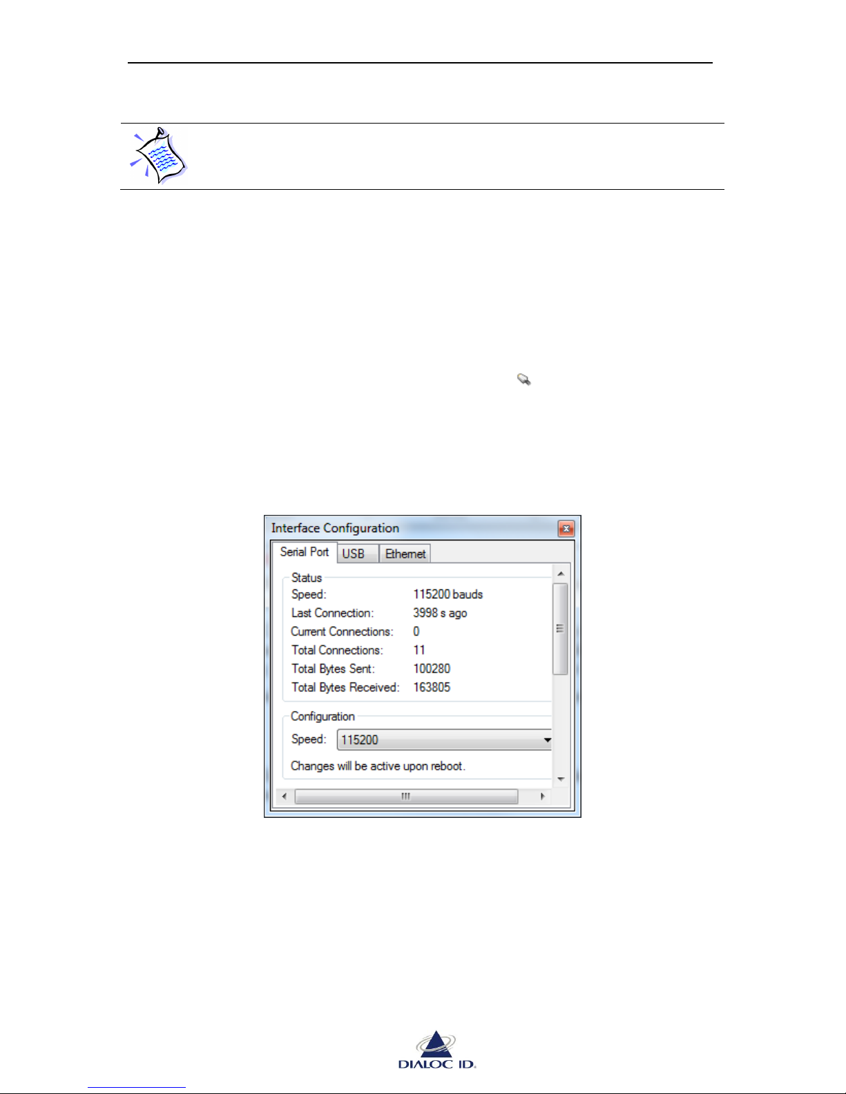
6.2.1 Serial Port Tab 6.2.1
You configure device’s serial communication interface and view its status on “Serial Port”
tab.
Figure 30: Interface Configuration panel (Serial Port tab)
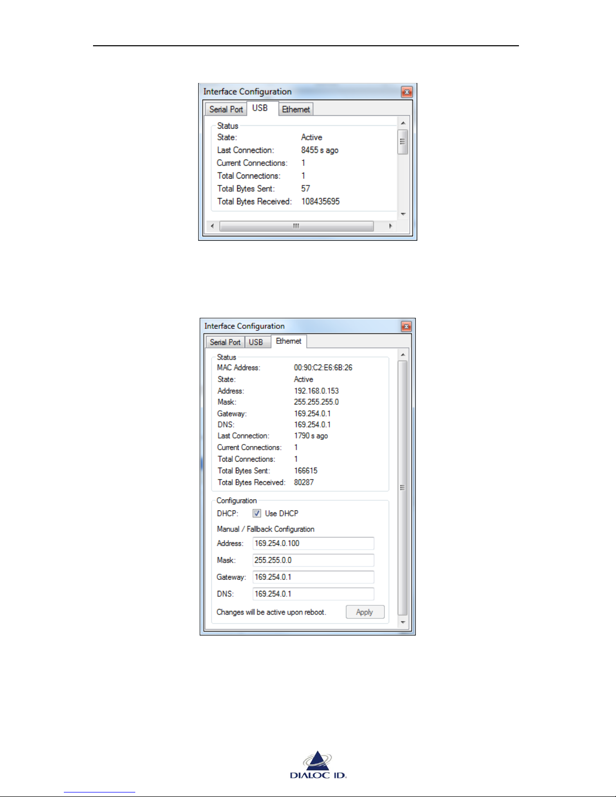
6.2.2 USB Tab
You view device’s USB communication interface status on “USB” tab.
Both Display & Keypad is not available on MCQ-Pro Reader.
Page 40
MCQ-PRO RFID Reader — Installation and Tuning Manual Version 1.00
Page 40 of 89
Figure 31: Interface Configuration panel (USB tab)
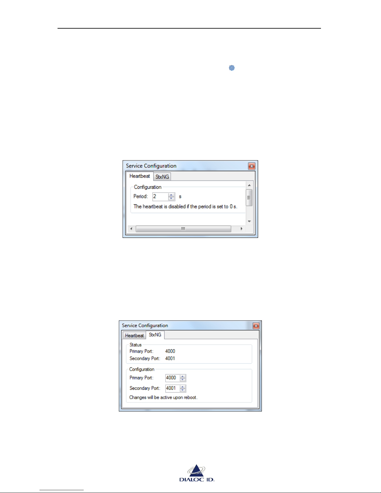
6.2.3 Ethernet Tab
You configure device’s Ethernet communication interface and view its status on “Ethernet”
tab.
Figure 32: Interface Configuration panel (Ethernet tab)
Page 41
MCQ-PRO RFID Reader — Installation and Tuning Manual Version 1.00
Page 41 of 89
6.3 Services Configuration
Open “Service Configuration” panel by clicking on the icon in the toolbar or by choosing
“Service Configuration” in the “Device” menu.
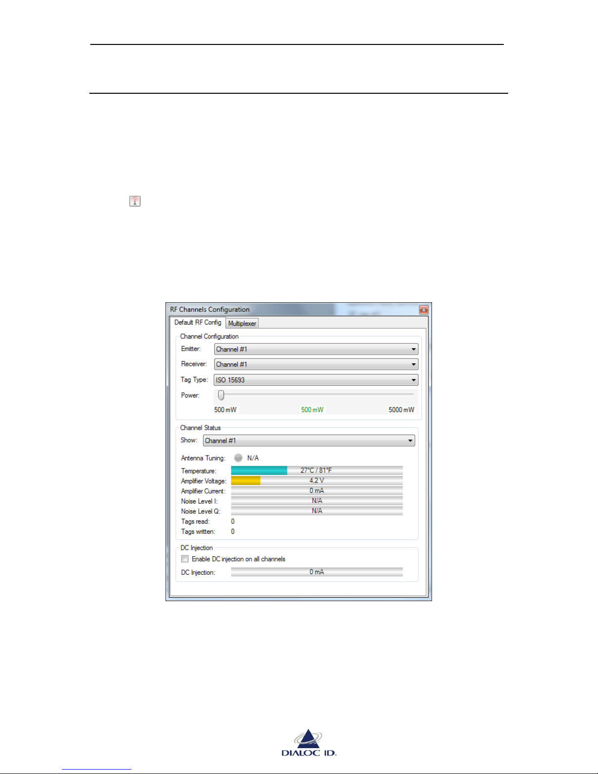
6.3.1 Heartbeat Tab
The heartbeat is a broadcasted UDP packet sent periodically on the network via the Ethernet
communication interface and is used for discovering the device and monitoring its proper
operation.
You configure the heartbeat period on this tab.
Figure 33: Service Configuration panel (Heartbeat tab)
6.3.2 StxNG Tab
The StxNG protocol is the native protocol of latest DIALOC ID RFID readers.
You can configure on which TCP port of the Ethernet communication interface the device
should listen for StxNG commands.
Figure 34: Service Configuration panel (StxNG tab)
Page 42
MCQ-PRO RFID Reader — Installation and Tuning Manual Version 1.00
Page 42 of 89
7 RF Channels Configuration
The radio field (RF) is the electromagnetic field emitted by antennas when channels of a
RFID device are powered on.
7.1 RF Channels Configuration
To define RF channels configuration, open “RF Channels Configuration” panel by clicking on
the icon in the toolbar or by choosing “RF Channels Configuration” in the “Radio” menu.
7.1.1 Default RF configuration
Default RF configuration represents the channel configuration that will be used for any
subsequent read/write operation.
Figure 35: RF Channels Configuration panel (Default RF Config tab)
Channel Configuration:
Select channels that should be emitting and receiving. If a Monostatic channel is set as a
receiver, it will also be an emitter. To know if a channel is monostatic, see section 0.
Select the tag type to use during subsequent read operations.
Page 43
MCQ-PRO RFID Reader — Installation and Tuning Manual Version 1.00
Page 43 of 89
Select the power to emit in milliwatts.
Channel Status:
Select the channel whose status should be displayed. This allows monitoring physical
parameters of the channel and detecting potential issues.
If a critical issue happens, a warning icon will appear beside the parameter.
When RF is turned on, device’s radio uses default RF configuration.
You need to turn RF on before performing any RFID operation such as starting a
default read (see section 8) or sending commands to tags (see section 9).
To turn RF on or off, click or button in the toolbar.
CAUTION: Make sure antennas are connected to channels you use before
turning the radio field on; otherwise it may severely damage the device.
DC Injection:
Enable this feature to add a DC component on the RF signal in order to power up an external
device through the RF cable.
7.1.2 Multiplexer Configuration
Multiplexer is used to program a sequence of channel activation to use during default read
(see section 8 for more information).
To use multiplexer configuration during default read, you must enable the
multiplexer read mode. See section 8.2.4 for more information.
Multiplexer cannot be used for sending commands to tags.
Page 44
MCQ-PRO RFID Reader — Installation and Tuning Manual Version 1.00
Page 44 of 89
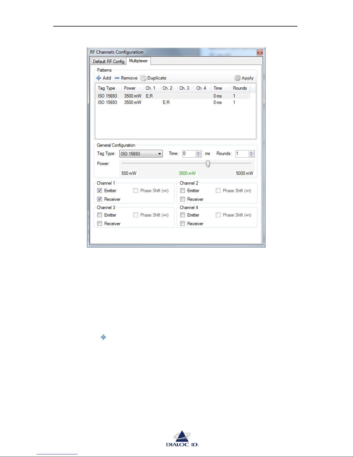
Figure 36: RF Channels Configuration panel (Multiplexer tab)
Patterns:
A pattern describes the channels that emit, their RF field phase shift, the channels that receive,
the power used, the tag type to read and a set of conditions that will cause switching to the
next pattern in the sequence.
A pattern must define time to be active and/or rounds (number of wake-up commands sent to
tags) it allows before the multiplexer switches to the next pattern (or the first if this pattern is
the last). If both switch conditions are defined, the first condition met will trigger the switch.
To add a new pattern:
1. Click on “ Add” button in “Patterns” box.
2. Select the tag type to read when the pattern is active.
3. Select the power to emit when the pattern is active (in milliwatts)
4. Select channels to emit and receive while respecting following constraints:
a. A pattern can have a maximum of two emitters and one receiver.
b. A Monostatic channel that is set as a receiver must also be an emitter.
5. Define a switch condition such as:
Page 45

MCQ-PRO RFID Reader — Installation and Tuning Manual Version 1.00
Page 45 of 89
a. Maximum time during which this pattern remains active (in milliseconds).
When this time elapses, the multiplexer switches to the next pattern (or the first
pattern if this pattern was the last one). A value of zero disables this limit.
b. Maximum rounds (number of Wake-up commands sent to the tags) during
which this pattern remains active. When this maximum is reached, the
multiplexer switches to the next pattern (or the first pattern if this pattern was
the last one). A value of zero disables this limit.
You can duplicate an existing pattern by clicking on “ Duplicate” button.
You can delete a pattern by clicking on “ Remove” button.
When you are finished defining patterns click on “ Apply” button to apply pattern
configuration.
Page 46

MCQ-PRO RFID Reader — Installation and Tuning Manual Version 1.00
Page 46 of 89
8 Default Read
Default read, also named asynchronous read, is a mode where the RFID device continuously
performs inventories on its channels to monitor tags.
In this section, we describe how to configure and perform default read.
8.1 Overview
To perform a default read, follow these steps:
1. Define RF channels configuration (see section 7 for more information).
2. Define read configuration (see section 8.2 for more information).
3. Optionally, change configuration of the tag type to read (see section 9 for more
information).
4. Click button in the toolbar.
CAUTION: Make sure an antenna is connected to channels you use before
turning the radio field on; otherwise it may severely damage the device.
5. Click button in the toolbar.
If the radio field is turned off, DIALOC ID MCQ-Pro will ask you to turn it on;
click “OK” to accept. Again, make sure an antenna is connected to the channel
before accepting.
6. Place tags in the radio field. Tags appear in events panel as they are read (see section 0
for more information).
7. Click button in the toolbar when you are finished reading. You may
want to turn the radio field off as well by clicking button.
8.2 Default Read Configuration
8.2.1 General
In “General” tab, you can define the behavior of DIALOC ID MCQ-Pro during default read.
Page 47
MCQ-PRO RFID Reader — Installation and Tuning Manual Version 1.00
Page 47 of 89
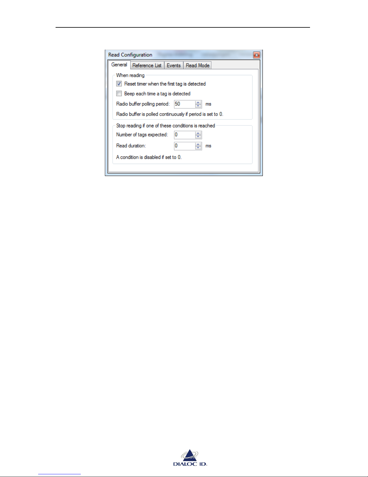
Figure 37: Read Configuration panel (General tab)
When reading:
Reset timer when the first tag is detected: requests DIALOC ID MCQ-Pro to reset timer
displayed in Radio Events/Statistics panels when the first tag is detected.
Beep each time a tag is detected: requests DIALOC ID MCQ-Pro to play system bell each
time a tag is detected.
Radio buffer polling period: changes the period used by DIALOC ID MCQ-Pro when
polling events from device’s radio. This is useful to simulate greater network latency.
Stop reading is one of these conditions is reached:
Number of tags expected: indicates that DIALOC ID MCQ-Pro stops reading as soon as
this number is reached.
Read duration: indicates that DIALOC ID MCQ-Pro should automatically stop reading
when this duration in milliseconds from start has elapsed.
Page 48
MCQ-PRO RFID Reader — Installation and Tuning Manual Version 1.00
Page 48 of 89
8.2.2 Reference List
In “Reference List” tab, you can define a set of tags you expect to read.
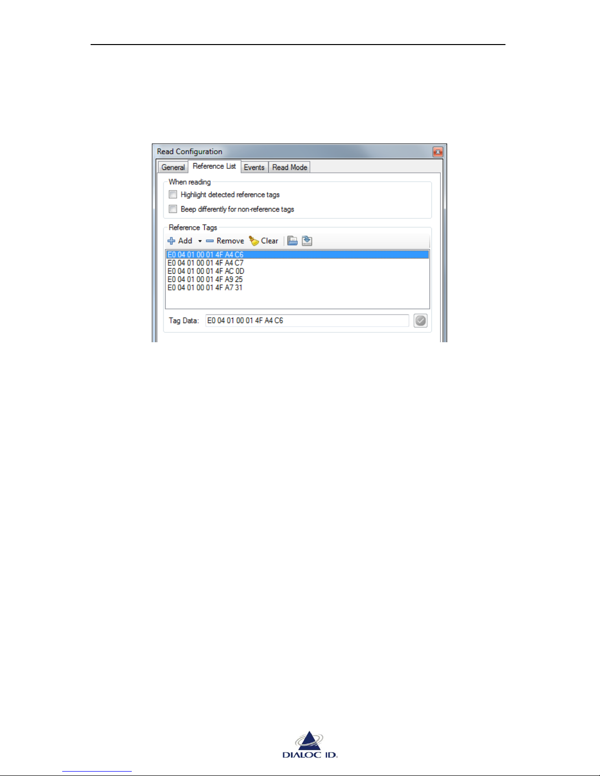
Figure 38: Read Configuration panel (Reference List tab)
When reading:
Highlight detected reference tags: requests DIALOC ID MCQ-Pro to highlight detected
reference tags in tag event panels.
Beep differently for non-reference tags: requests DIALOC ID MCQ-Pro to play a special
system bell each time a non-reference tag is detected in RF.
Reference Tags:
Add: adds tags in reference list. You can add tags manually or from tag event panels. Tags
are defined by data/UID returned during default read. Use “Tag Data” field below
reference list to modify data/UID of selected tag.
Remove: removes selected tag from reference list.
Clear: removes all tags from reference list.
Load: loads tags in reference list from a CSV file. Each line of the file must contain the
data of a single tag as hexadecimal bytes.
Example (whitespace between each byte is optional):
E0 04 01 00 01 4F A4 C6
E0 04 01 00 01 4F A4 C7
E0 04 01 00 01 4F AC 0D
E0 04 01 00 01 4F A9 25
E0 04 01 00 01 4F A7 31
Save: saves tags in reference list to a CSV file.
Page 49
MCQ-PRO RFID Reader — Installation and Tuning Manual Version 1.00
Page 49 of 89
8.2.3 Events
A radio event happens during default read when an interesting action concerning tags has
occurred.
Before starting a default read, you must select radio events you need in
drop down menu of toolbar.
Each radio event is reported in its own panel during default read. See section 0
for more information.
There are several types of radio events that may occur during default read:
“Tag Read” event occurs each time a tag frame is detected in radio field.
“New Tag” event occurs the first time a tag is detected in radio field.
“Tag In” and “Tag Out” events come in pair ( ) and occur respectively when
a tag enters or leaves the radio field.
“No Read” event occurs if no tag has been read when reading stops (applicable
only if input triggered reading is enabled; see section 8.2.4 for more information).
“Scan once completed” event occurs if “Scan Once” read mode is activated and when
the current scan is over.
You can configure the radio events settings on “Events” tab of “ Read Configuration”
panel.
If you enable “Tag In” or “Tag Out” event but not the other, both events will be
temporarily enabled during asynchronous reading.
Page 50
MCQ-PRO RFID Reader — Installation and Tuning Manual Version 1.00
Page 50 of 89
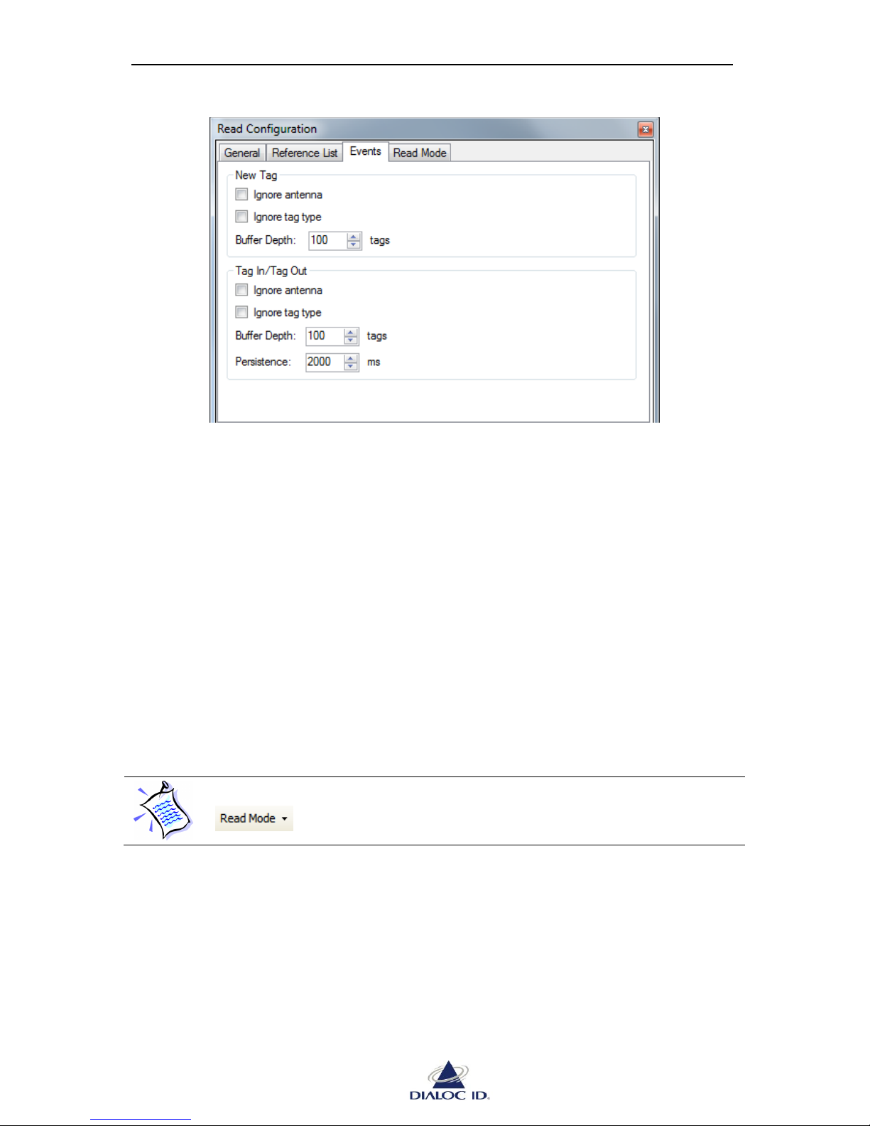
Figure 39: Read Configuration panel (Events tab)
New Tag:
Ignore antenna: indicates that tag data detected by multiple antennas should be reported
only once.
Ignore tag type: indicates that tags of different types with same tag data should be
reported only once.
Buffer Depth: represents the number of tags to be stored in internal radio buffer for “Tag
New” event.
Tag In/Tag Out:
Ignore antenna, Ignore tag type and Buffer Depth settings are similar to “New Tag” ones.
Persistence: represents the number of milliseconds that should elapse without having
detected the tag in the radio field before triggering a “Tag Out” event.
8.2.4 Read Mode
Read mode defines the radio device behavior during default read.
Before starting a default read, you must select read mode options you need in
drop down menu of toolbar.
There are several read mode options available:
“Enable Multiplexer” indicates, when reading asynchronously, whether radio should
use multiplexer's configuration or, otherwise, default RF configuration.
“Enable Input Trigger” indicates that radio should start/stop reading when the state of
digital input #1 of IO Set #1 is set to its active/inactive level.
“Enable Output Feedback” indicates, when reading asynchronously, that radio should
report read activity by changing states of digital outputs..
Page 51
MCQ-PRO RFID Reader — Installation and Tuning Manual Version 1.00
Page 51 of 89
With a MCQ-Pro Reader, if this mode is active, the reader uses GPIO Output
#2 to report reading activity. GPIO Output #2 is activated when the reader
“sees” tags in the RF field. The time an output remains active after the
corresponding event has occurred is software configurable.
“Enable Tunnel Feedback” is for DIALOC ID internal use only.
“Enable Scan Once” indicates, when reading asynchronously, that the radio should
automatically stop reading after:
o In “default RF” read mode: one single round (not valid with C210 & C220
tags).
o In “multiplexer” read mode: having scan all the existing patterns.
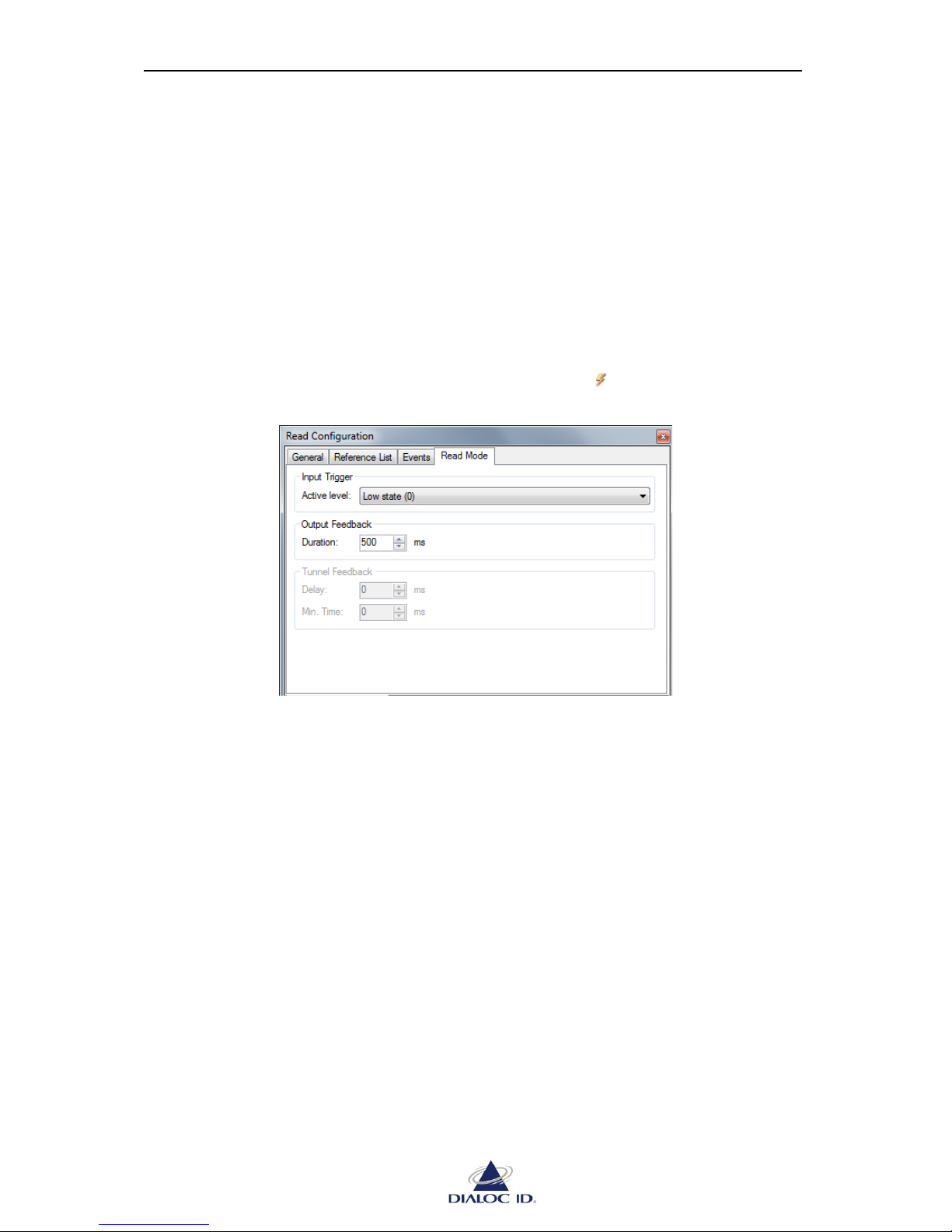
You can configure read mode settings on “Read Mode” tab of “ Read Configuration” panel.
Figure 40: Read Configuration panel (Read Mode tab)
Input Trigger:
Active Level: indicates the active level when radio should start reading (ie: on Low
state “0” or on High state “1”)
Output Feedback:
Duration: indicates the duration in milliseconds of read activity feedback.
Tunnel Feedback:
Those settings are for DIALOC ID internal use only.
Page 52
MCQ-PRO RFID Reader — Installation and Tuning Manual Version 1.00
Page 52 of 89
8.3 Radio Event Panels
Radio event panels display events received from device’s radio during default read.
Radio event panels are automatically opened when you start reading depending on enabled
radio events (see 8.2.3 for more information). You can manually open radio event panels from
“Radio > Default Read” menu.
8.3.1 Tag Read Events
You can open “ Tag Read Events” panel from “Radio > Default Read” menu.
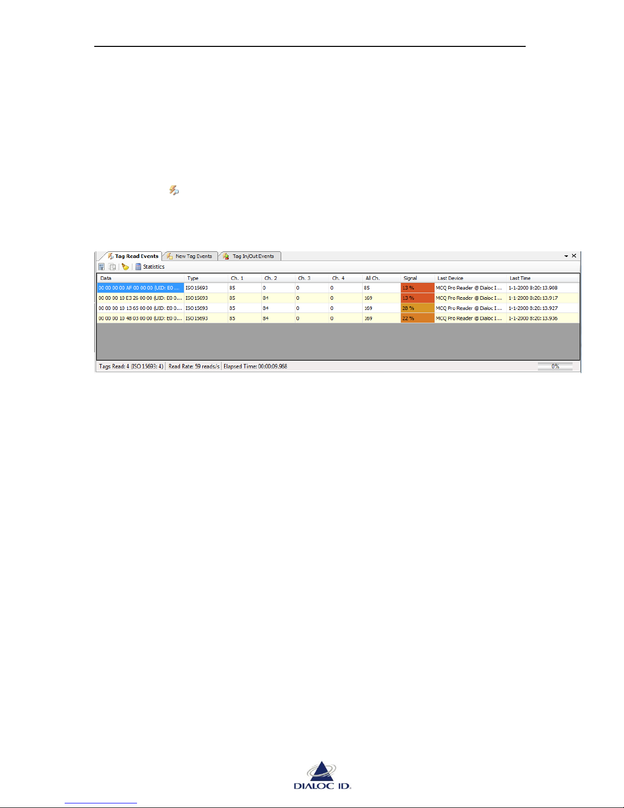
A “Tag Read” event occurs each time a tag is detected in radio field. Each “Tag Read” event
makes corresponding tag appear in “Read Events” panel.
Figure 41: Read Events panel
The embedded toolbar allows you to open “Statistics” panel (see section 8.4 for more
information) and to select all, copy some or clear all rows from the event list.
Each read event has the following fields:
“Data” contains data received from the tag.
“Type” contains tag type.
“Ch. n” contains read count of the tag on channel #n.
“All Ch.” contains total read count of the tag.
“Signal Level” contains the level in percent of the signal received from the tag. You
can filter tags with a low signal level by setting the “Signal level threshold” parameter
corresponding to their type (see section 9 for more information).
“Last Device”/”Last Time” contains last device and time this tag was read on.
Below the event list, an embedded status bar contains the following fields:
“Tags Read” shows number of tags read so far.
“Read Rate” shows number of tag events per second.
“Elapsed Time” shows time having elapsed since read has started.
The gauge on the right side displays the filling level of radio’s internal event buffer. If
this gauge reaches 100% some events may be lost.
Page 53
MCQ-PRO RFID Reader — Installation and Tuning Manual Version 1.00
Page 53 of 89
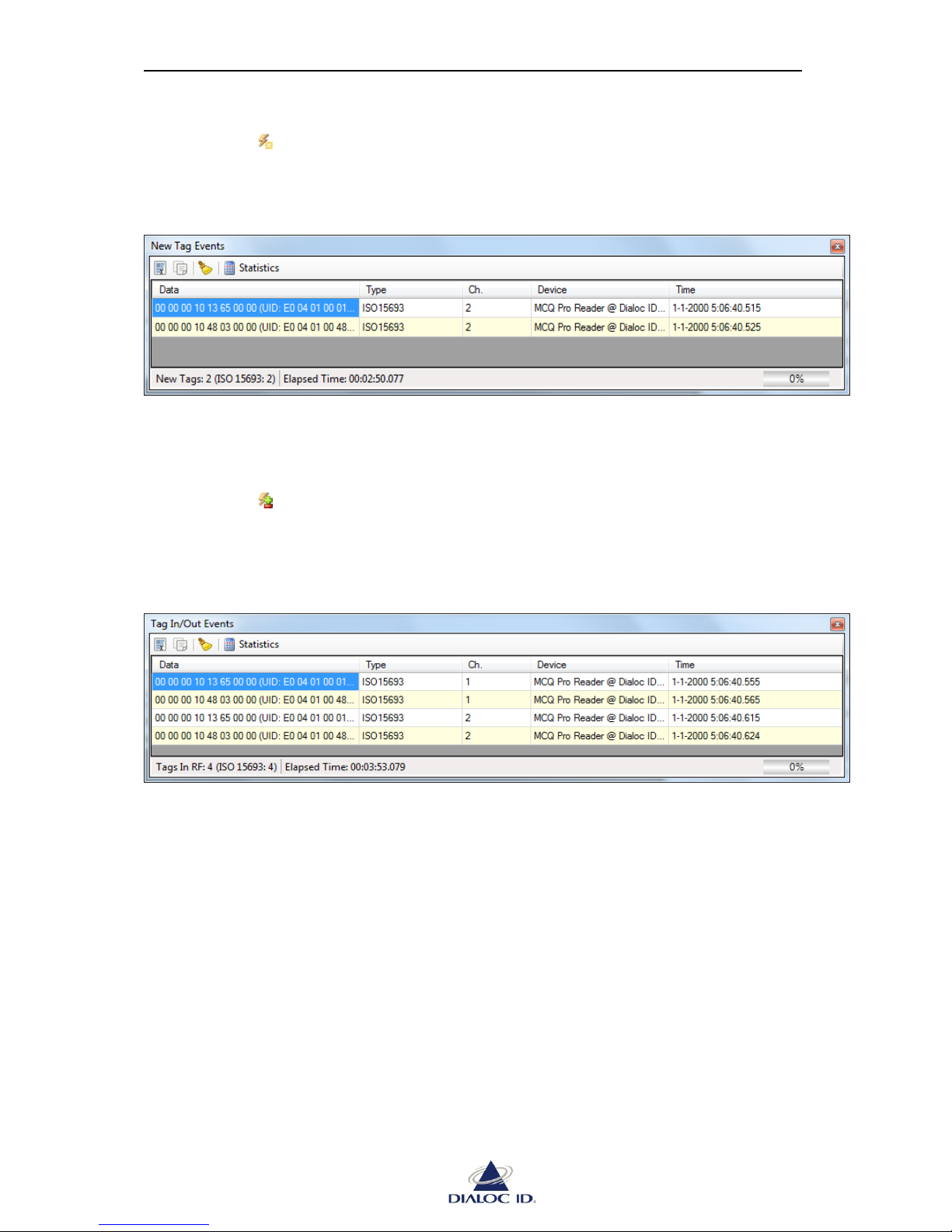
8.3.2 New Tag Events
You can open “ New Tag Events” panel from “Radio > Default Read” menu.
A “New Tag” event occurs the first time a tag is detected in radio field. Each “New Tag”
event makes corresponding tag appear in “New Events” panel.
Figure 42: New Events panel
“New Tag Events” panel is similar to “Tag Read Events” panel; please refer to section 8.3.1
for more information.
8.3.3 Tag In/Tag Out Events
You can open “ Tag In/Out Events” panel from “Radio > Default Read” menu.
“Tag In” and “Tag Out” events come in pair and occur respectively when a tag enters or exits
the radio field. Each “Tag In” or “Tag Out” event makes corresponding tag appear or
disappear in “Tag In/Out Events” panel.
Figure 43: In/Out Events panel
“New Events” panel is similar to “Read Events” panel; please refer to section 8.3.1 for more
information.
Page 54
MCQ-PRO RFID Reader — Installation and Tuning Manual Version 1.00
Page 54 of 89
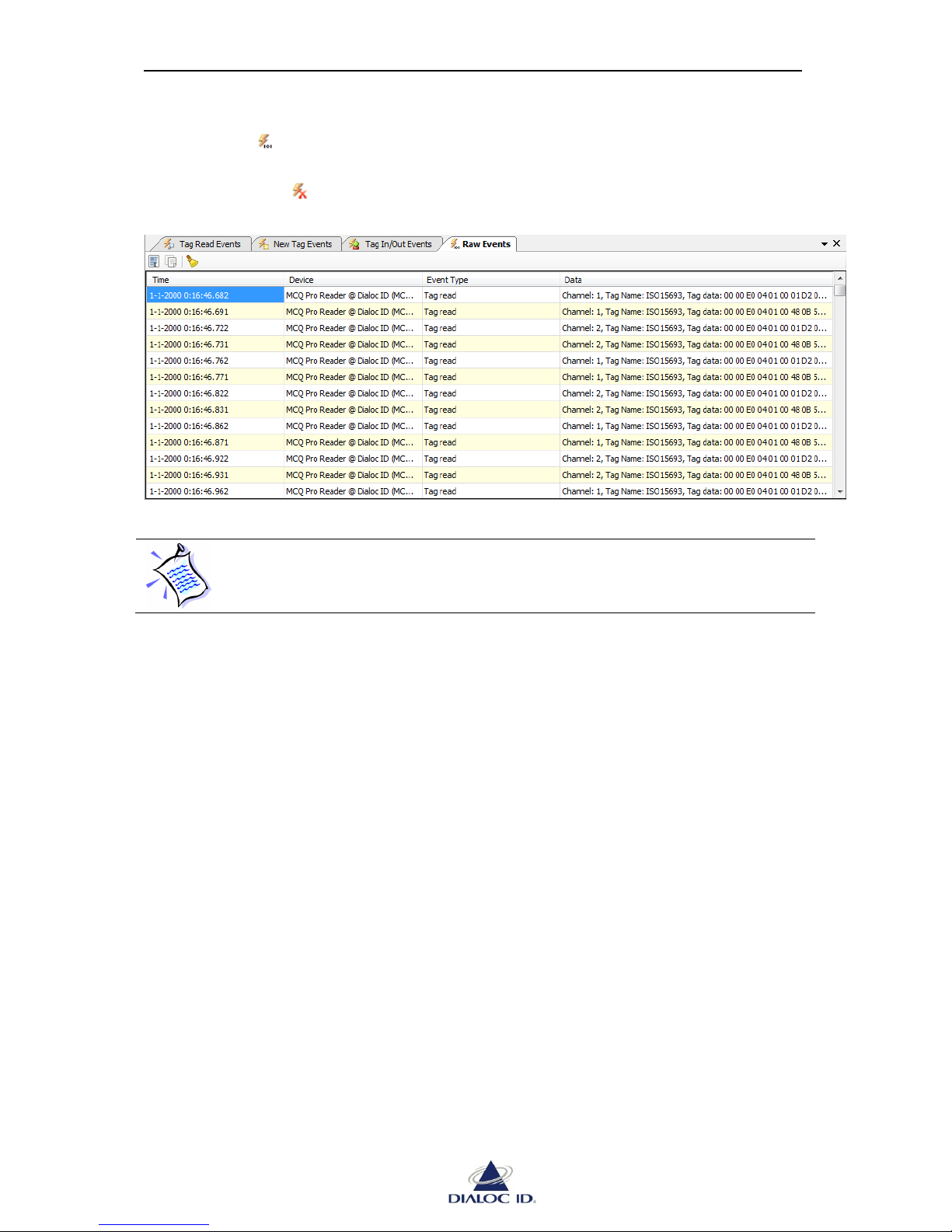
8.3.4 Raw Events
You can open “ Raw Events” panel from “Radio > Default Read” menu.
“Raw Events” panel shows all events having occurred on device’s radio. It permits in
particular to watch “ No Read” events.
Figure 44: Raw Events panel
As hundreds of radio events can occur by second, displaying all of them is a CPU
intensive operation and may lower reading performance. Close “Raw Events”
panel when you do not need it.
Page 55
MCQ-PRO RFID Reader — Installation and Tuning Manual Version 1.00
Page 55 of 89
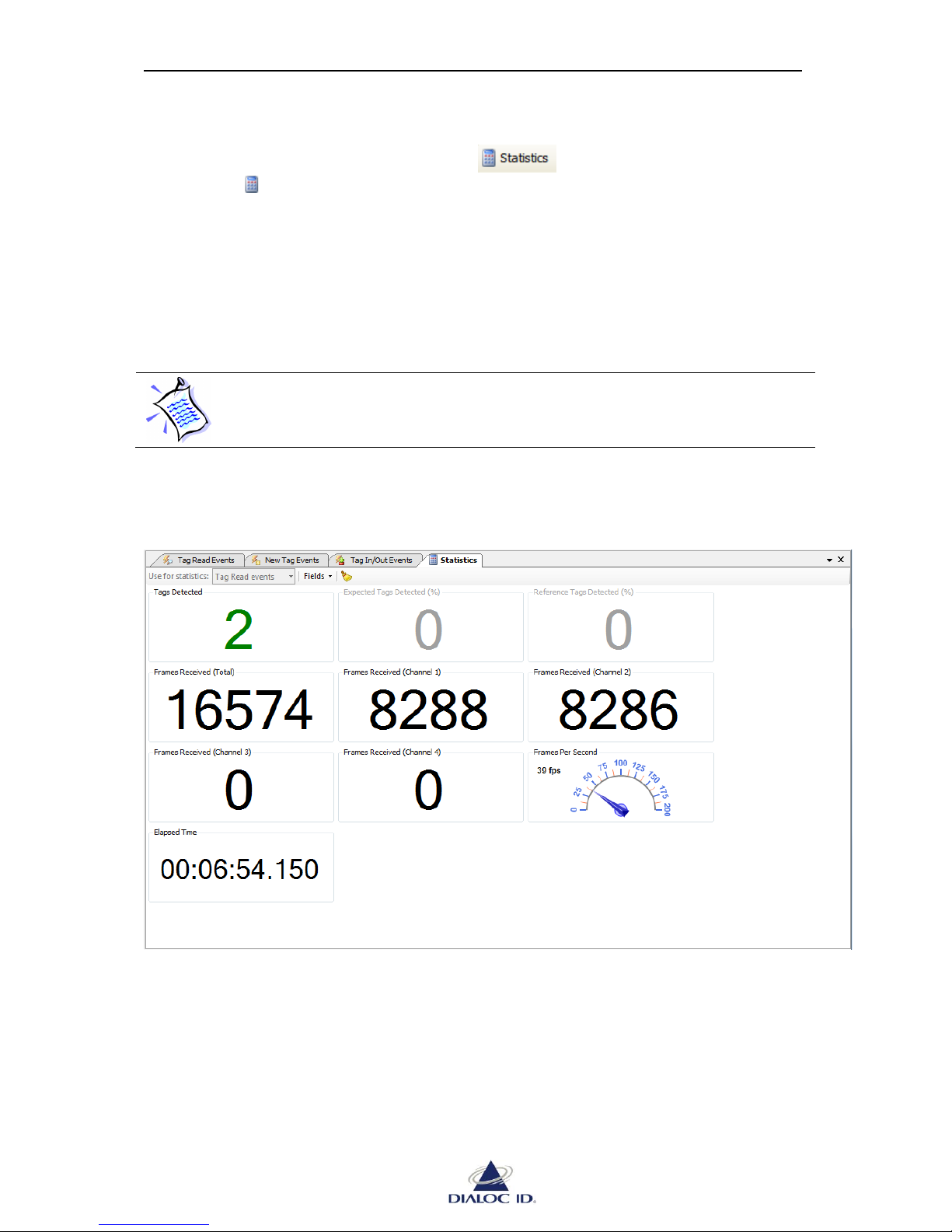
8.4 Statistics panel
You can open “Statistics” panel by clicking on button on radio events panels or
by choosing “ Statistics” in “Radio > Default Read” menu.
“Statistics” panel shows read statistics such as the number of tags detected, the number of
event frames received by channel or globally, the event frame rate and elapsed time since
reading started.
If several radio events are enabled (see 8.2.3 for more information), you can change the event
type used for statistics calculation in “Use for statistics” drop down menu of embedded
toolbar.
If the event type used for statistics calculation is not enabled (as explained in
8.2.3), statistics will not be updated during default read.
You can hide fields you do not use by unchecking them in “Fields” drop down menu of
embedded toolbar.
Figure 45: Statistics panel
Page 56
MCQ-PRO RFID Reader — Installation and Tuning Manual Version 1.00
Page 56 of 89
9 Tag Parameters and Commands
Tag parameters are specific to tag type and define:
Communication link characteristics between such tags and device
Options to apply when reading asynchronously (default read) such tags
Tag commands are special commands. For example, these commands may allow
reading/writing tags’ memory.
Many tag parameters and commands are specific to tag types, so please refer to manufacturer
specifications according to the tag types.
Before sending any command to tags, you should define default radio configuration and turn
the radio field on (see section 7.1.1 for more information)
9.1 C210
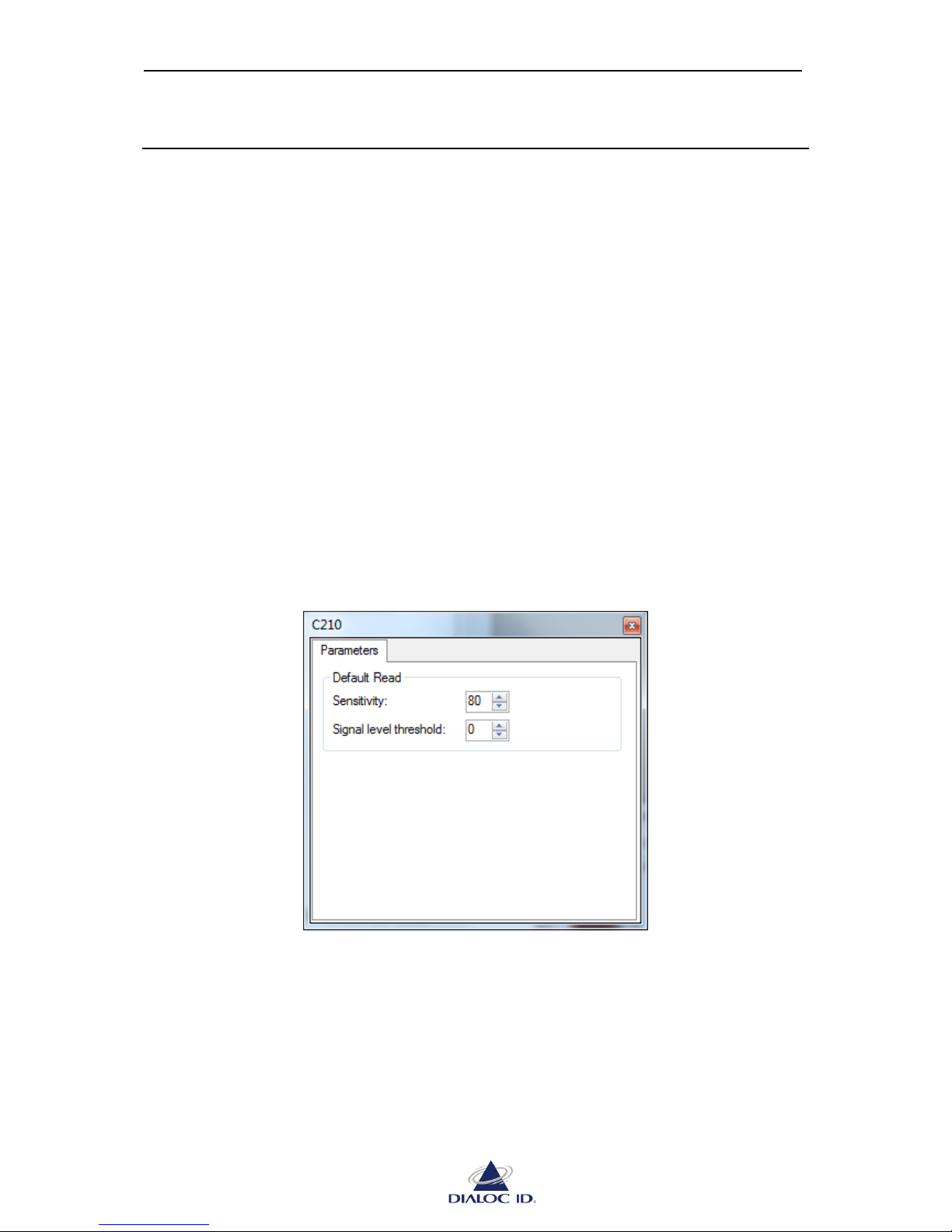
Open “C210” panel by choosing “C210” in the “Radio > Tag Parameters and Commands”
menu.
9.1.1 Parameters tab
Figure 46: C210 panel (Parameters tab)
Default Read
Sensitivity: defines reader sensitivity when attempting to detect a C210 in the RF field
(C210 is TTF). The higher the value, the higher the sensitivity.
Signal level threshold: a tag will be reported only if its signal level is greater or equal
to this threshold during asynchronous read. All tags will be reported if the threshold is
set to 0.
Page 57
MCQ-PRO RFID Reader — Installation and Tuning Manual Version 1.00
Page 57 of 89
9.2 C220
Open “C220” panel by choosing “C220” in the “Radio > Tag Parameters and Commands”
menu.
9.2.1 Parameters tab
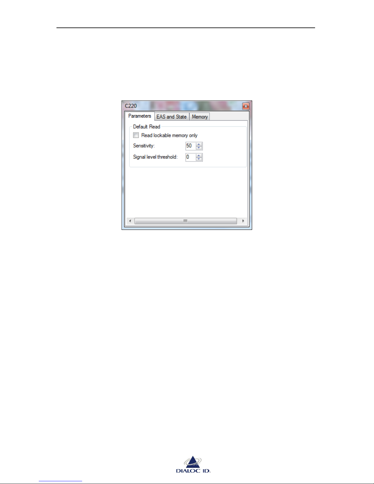
Figure 47: C220 panel (Parameters tab)
Default Read
Read lockable memory only: specifies if only lockable memory should be read during
asynchronous read process, even if tags are in long reply mode.
Sensitivity: defines reader sensitivity when attempting to detect a C220 in the RF field
(C220 is TTF). The higher the value, the higher the sensitivity.
Signal level threshold: a tag will be reported only if its signal level is greater or equal
to this threshold during asynchronous read. All tags will be reported if the threshold is
set to 0.
Page 58
MCQ-PRO RFID Reader — Installation and Tuning Manual Version 1.00
Page 58 of 89
9.2.2 EAS and State tab
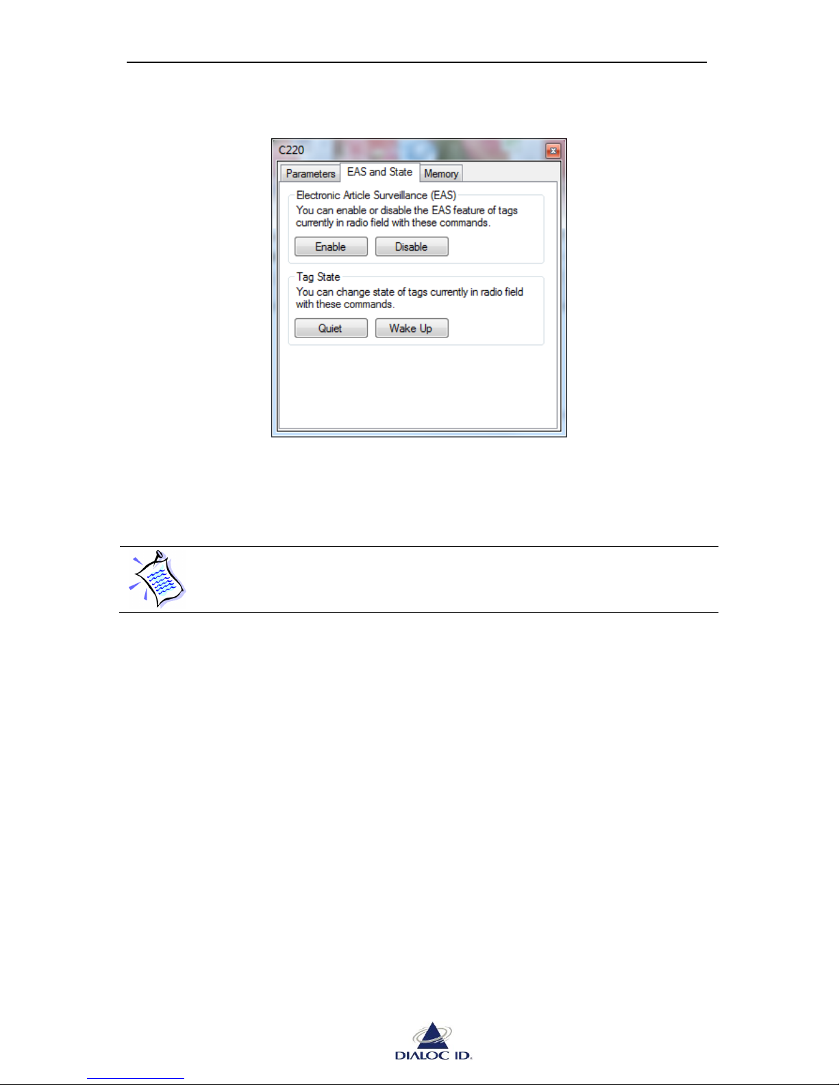
Figure 48: C220 panel (Parameters tab)
Electronic Article Surveillance (EAS)
Click “Enable”/“Disable” to enable/disable EAS state of all C220 tags in the RF field.
Tags must be locked for this operation to function properly. To change EAS state
of unlocked tags, use memory writing operation instead.
Tag State
To change state of tags, place C220 tags in radio field and:
Click “Quiet” button to request tags to stay quiet;
Click “Wake Up” to exit tags from quiet state.
Page 59
MCQ-PRO RFID Reader — Installation and Tuning Manual Version 1.00
Page 59 of 89
9.2.3 Memory tab
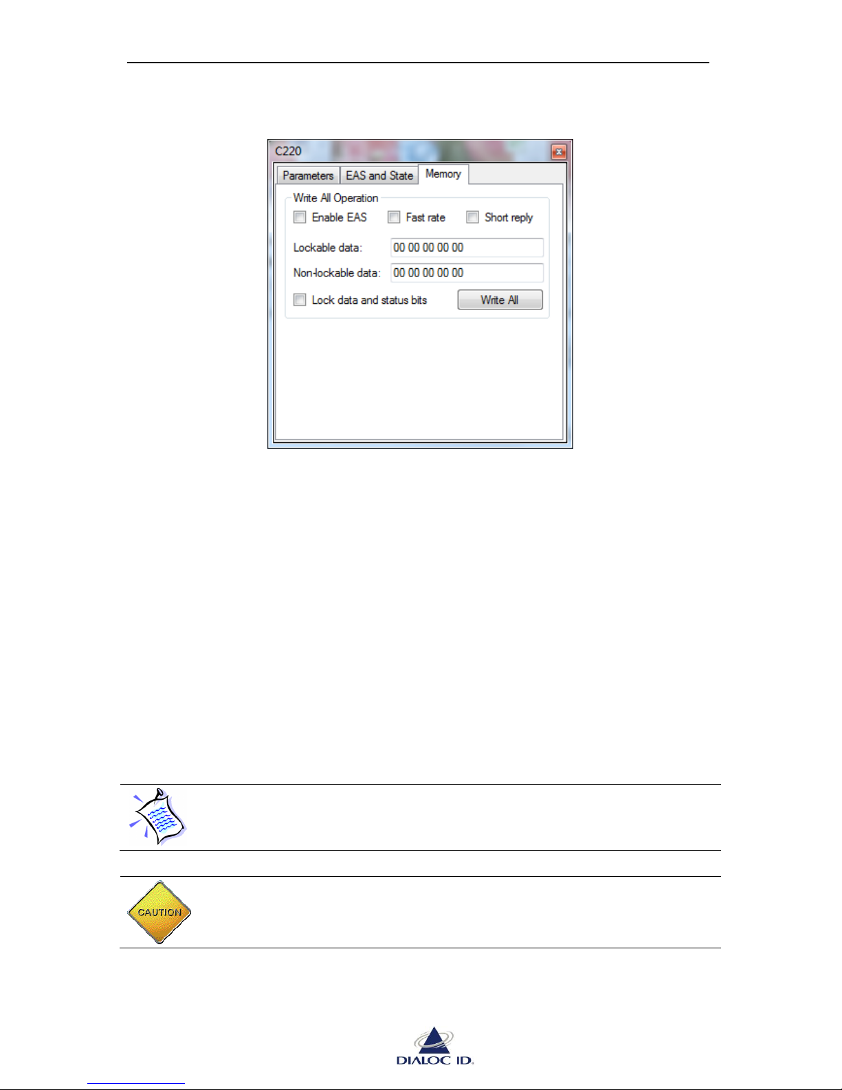
Figure 49: C220 panel (Parameters tab)
Write Operation
To write memory and status bytes of all C220 tags in radio field, enter lockable and nonlockable data (in hexadecimal) to write, choose status bytes to set and click “Write All”.
The status bits available are:
Enable EAS: Specifies if EAS should be enabled or disabled (not lockable).
Fast rate: Specifies if the reply rate should be fast (~16 ms) or normal (~33 ms) during
asynchronous read process (lockable).
Short reply: Specifies if the reply size should be short (only lockable memory data is
sent) or long (both non-lockable and lockable memory data are sent) during
asynchronous read process (lockable).
Lock data and status bits: Specifies if lockable memory (lockable data and status bits)
should be locked. This operation is irreversible. Once lockable memory is locked,
EAS state can be changed in "EAS and State" tab.
Write operation does not perform verification.
CAUTION: Lockable data, Fast rate bit and Short reply bit cannot be modified
once the Lock bit is set using “Lock data and status bits” option.
Page 60
MCQ-PRO RFID Reader — Installation and Tuning Manual Version 1.00
Page 60 of 89
9.3 I-Code 1 (C270)
Open “I-Code 1” panel by choosing “I-Code 1” in the “Radio > Tag Parameters and
Commands” menu.
9.3.1 Parameters tab
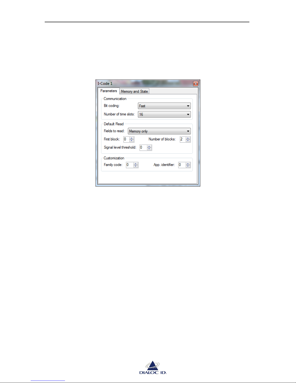
Figure 50: I-Code 1 panel (Parameters tab)
Communication
Bit Coding: to define bit rate used for uplink communication.
Number of time slots: to change the number of time slots used during default read.
Default Read
Fields to read: to define whether only tag memory and/or UID should be read during
default read process (unselected read). The 64-bit UID of an I-Code tag is stored in its
first memory block (32 LSBits) and its second memory block (32 MSBits).
The following options are available:
Memory Only: Read memory blocks only. Memory blocks are reported
sequentially.
UID Only: Read the UID from tag’s first and second memory blocks. The UID
will be reported MSB first.
Both memory and UID: Read the UID and memory blocks. The UID (MSB
first) and then memory blocks will be reported sequentially.
First block and Number of blocks: to choose which blocks of tag memory to read
during default read process (unselected read).
Signal level threshold: a tag will be reported only if its signal level is greater or equal
to this threshold during asynchronous read. All tags will be reported if the threshold is
set to 0.
Customization
If Family Code (in hexadecimal) is not null, only tags with the same code will reply.
Page 61
MCQ-PRO RFID Reader — Installation and Tuning Manual Version 1.00
Page 61 of 89
If Application Identifier (in hexadecimal) is not null, only tags with the same identifier
will reply.
A null value disables the family code or the application identifier.
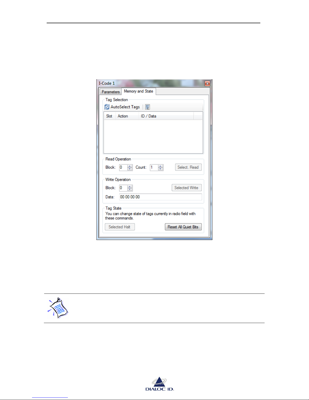
9.3.2 Memory and State tab
Figure 51: I-Code 1 panel (Memory and State tab)
Tag Selection
Tag selection is mandatory before performing read, write or halt commands.
To select tags in radio field, click “AutoSelect Tags” button. Each selected tag is affected to a
distinct time slot and displayed in the list.
The number of time slots defined in I-Code parameters (see section 9.1.1) is used
while performing tag selection. If there were not enough time slots available to
select all tags, you should try to change this setting to a higher number or to
remove some tags from radio field.
Read Operation
To perform selected read, choose one or several tags from “Tag Selection” list, enter the first
block and the number of blocks to read and click “Select. Read”.
Write Operation
To perform selected write, choose one or several tags from “Tag Selection” list, enter the
block and the data (in hexadecimal) to write and click “Selected Write”.
Page 62

MCQ-PRO RFID Reader — Installation and Tuning Manual Version 1.00
Page 62 of 89
Tag State
Halted I-Code tags remain quiet as long as they stay in radio field. To perform selected halt,
choose one or several tags from “Tag Selection” list and click “Selected Halt”.
You can quiet I-Code tags permanently by setting their quiet bit with selected write command
(see NXP I-Code specifications for more information). To clear all quiet bits of tags currently
in radio field, click “Reset All Quiet Bits”.
Page 63
MCQ-PRO RFID Reader — Installation and Tuning Manual Version 1.00
Page 63 of 89
9.4 ISO 15693
Open “ISO 15693” panel by choosing “ISO 15693” in the “Radio > Tag Parameters and
Commands” menu.
9.4.1 Parameters Tab
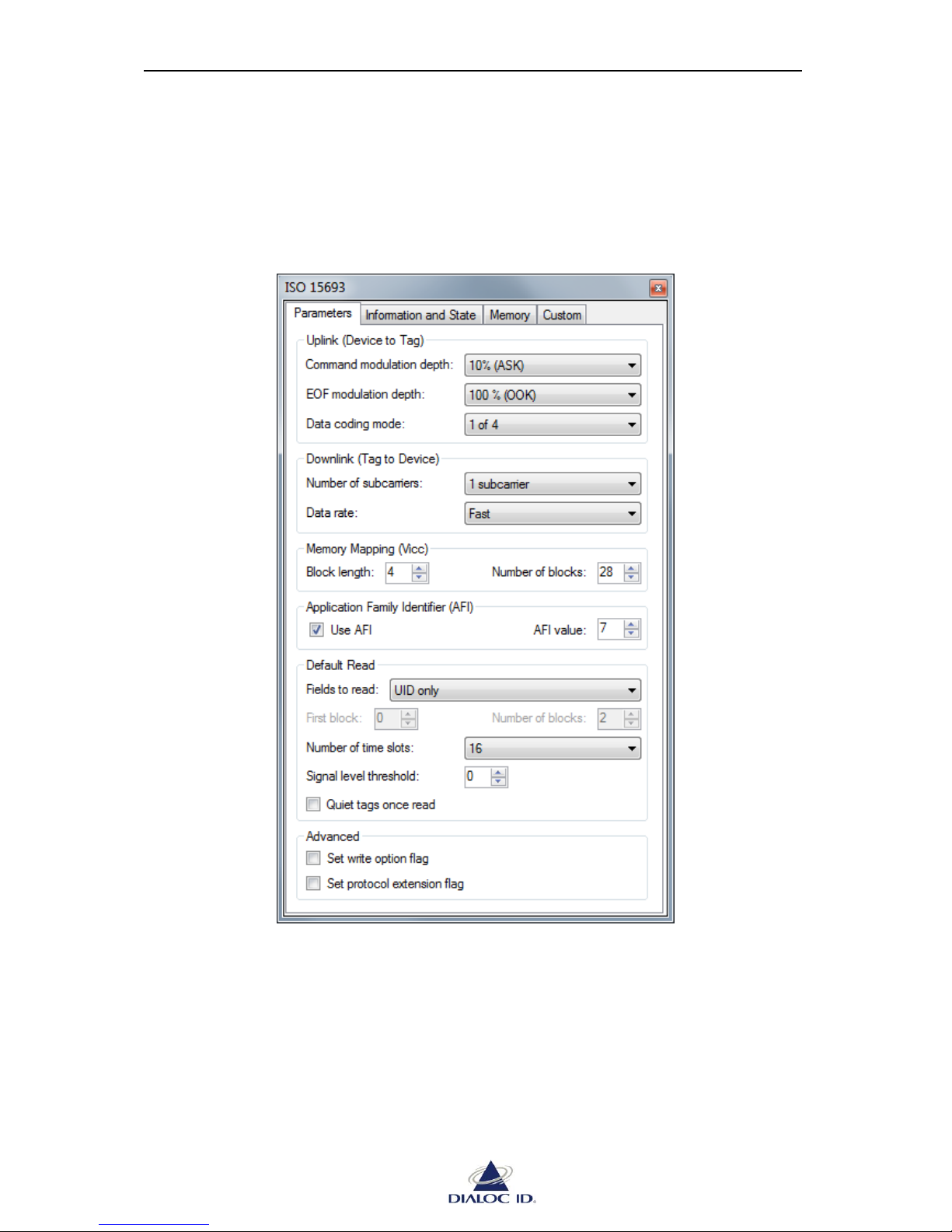
Figure 52: ISO 15693 panel (Parameters tab)
Uplink (Device to Tag)
Device communicates with tags using ASK (Amplitude Shift Keying) or OOK (On/Off
Keying). You can choose the modulation depth in “Command modulation depth” and “EOF
(End Of Frame) modulation depth” lists.
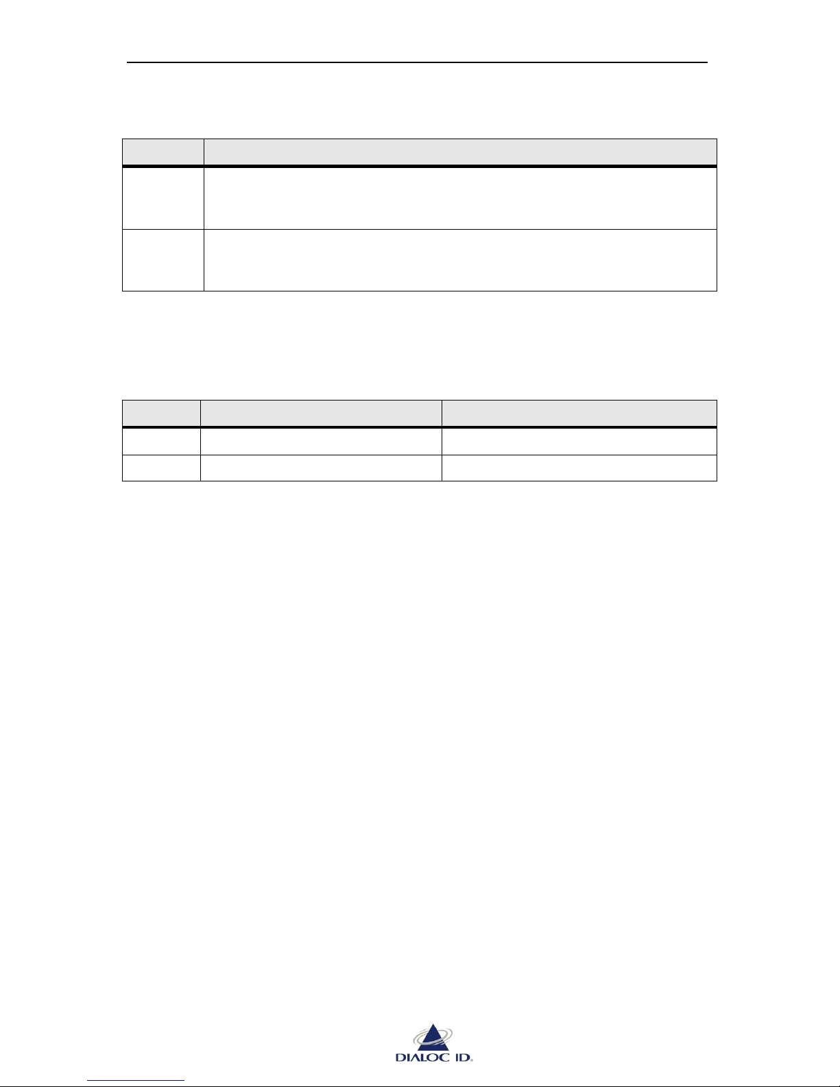
ISO 15693 tags can encode data in one of two modes as shown in Table 1.
Page 64
MCQ-PRO RFID Reader — Installation and Tuning Manual Version 1.00
Page 64 of 89
Table 1: Data Coding Modes
Mode
Description
1 of 4
The value is represented by the position of one pause determined two bits at a
time. Four successive pairs of bits form a byte, where the least significant pair of
bits is transmitted first.
1 of 256
The value of one single byte is represented by the position of one pause. The
position of the pause on 1 of 256 successive time periods of 256 divided by the
carrier frequency determines the value of the byte.
Downlink (Tag to Device)
One or two sub-carriers can be used with ISO 15693 tags and a slow or fast data rate can be
applied. Data rates in relation to the number of sub-carriers are shown in Table 2.
Table 2: Data Rates
Data Rate
Single Sub-carrier
Dual Sub-carrier
Slow
6.62 Kbps (fC/2048)
6.67 Kbps (fC/2032)
Fast
26.48 Kbps (fC/512)
26.69 Kbps (fC/508)
Memory Mapping (Vicc)
ISO 15693 tags memory is organized into fixed size blocks. Up to 256 blocks can be
addressed and each block can consist of up to 32 bytes (256 bits). This provides a maximum
memory size of 8 kilobytes (KB).
You can configure with “Block length” and “Number of blocks” fields the memory
organization of your ISO 15693 tags. If you do not know this memory organization, see
section 9.2.2 to get it.
Application Family Identifier (AFI)
A hexadecimal AFI filter can be selected for any further inventory. See ISO 15693
specification for more information.
Default Read
“Fields to read” defines whether only tag memory or tag memory and UID should be read
during default read process.
The following options are available:
UID Only: Read the UID. The UID will be reported MSB first.
Both memory and UID: Read the UID and memory blocks. The UID (MSB first) and
then memory blocks will be reported sequentially.
First block and Number of blocks: to choose which blocks of tag memory to read during
default read process.
“Number of time slots” list permits you to change the number of time slots used during
default read.
Page 65
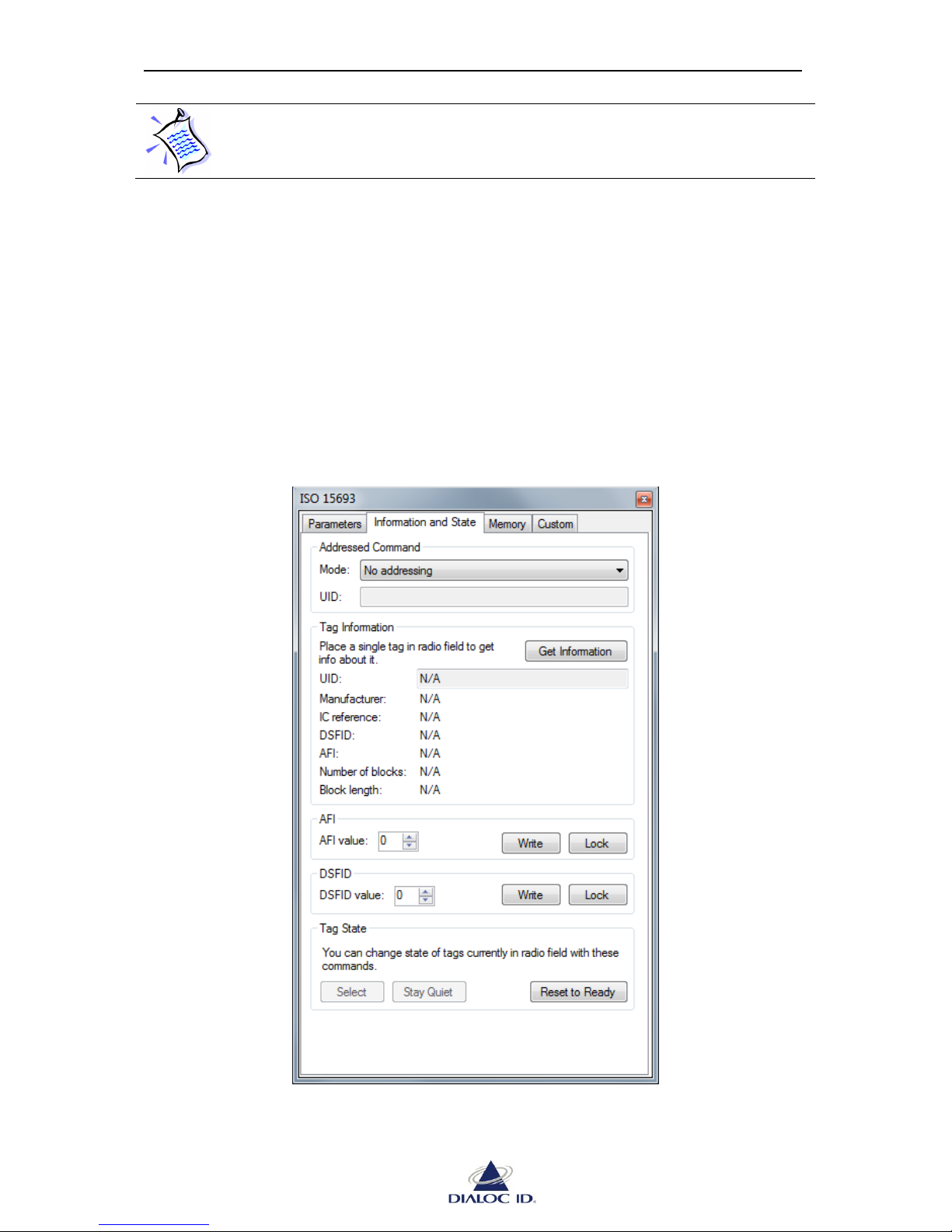
MCQ-PRO RFID Reader — Installation and Tuning Manual Version 1.00
Page 65 of 89
Setting the number of time slots to 1 disables anti-collision capability (i.e. tags
must be read one at a time)
“Signal level threshold” permits to report a tag only if its signal level is greater or equal to this
threshold during asynchronous read. All tags will be reported if the threshold is set to 0.
“Quiet tags once read” requests tag to stay quiet once read.
Advanced
“Set write option flag” specifies if write option flag should be set for all subsequent ISO
15693 write and lock commands. This behavior depends on tag manufacturer. See tag
specifications for more information.
“Set protocol extension flag” specifies if protocol extension flag should be set for all
subsequent ISO 15693 commands.
9.4.2 Information and State Tab
Figure 53: ISO 15693 panel (Information and State tab)
Page 66
MCQ-PRO RFID Reader — Installation and Tuning Manual Version 1.00
Page 66 of 89
Addressed Command
If you want to perform addressed commands, you can choose in “Mode” the type of
addressing to use.
Table 3: Addressing Modes
Mode
Description
No Addressing
Commands are executed by all tags.
Selected tags
Commands are executed only by tags having the selected state.
Addressed using
UID
Commands are executed only by tags having a matching UID (8 hex
bytes)
Tag Information
Place a single ISO 15693 tag in radio field and click “Get Information” button to obtain
information about the tag.
You can get this way the memory organization supported by your ISO 15693 tags and
configure device’s radio as explained in section 9.2.1.
Application Family Identifier (AFI)
To set AFI of some tags, choose an addressing mode, enter AFI as a hexadecimal byte in
“AFI value” field and click “Write” button.
Click “Lock” button to protect permanently AFI from any changes.
Data Storage Format Identifier (DSFID)
To set DSFID of some tags, choose an addressing mode, enter DSFID as a hexadecimal byte
in “DSFID value” field and click “Write” button.
Click “Lock” button to protect permanently DSFID from any changes.
Tag State
ISO 15693 tags support selected and quiet states.
To change state of tags, place ISO 15693 tags in radio field, choose an addressing mode and:
Click “Select” button to select tags;
Click “Stay Quiet” button to request tags to stay quiet;
Click “Reset to Ready” to exit tags from selected or quiet states.
Page 67
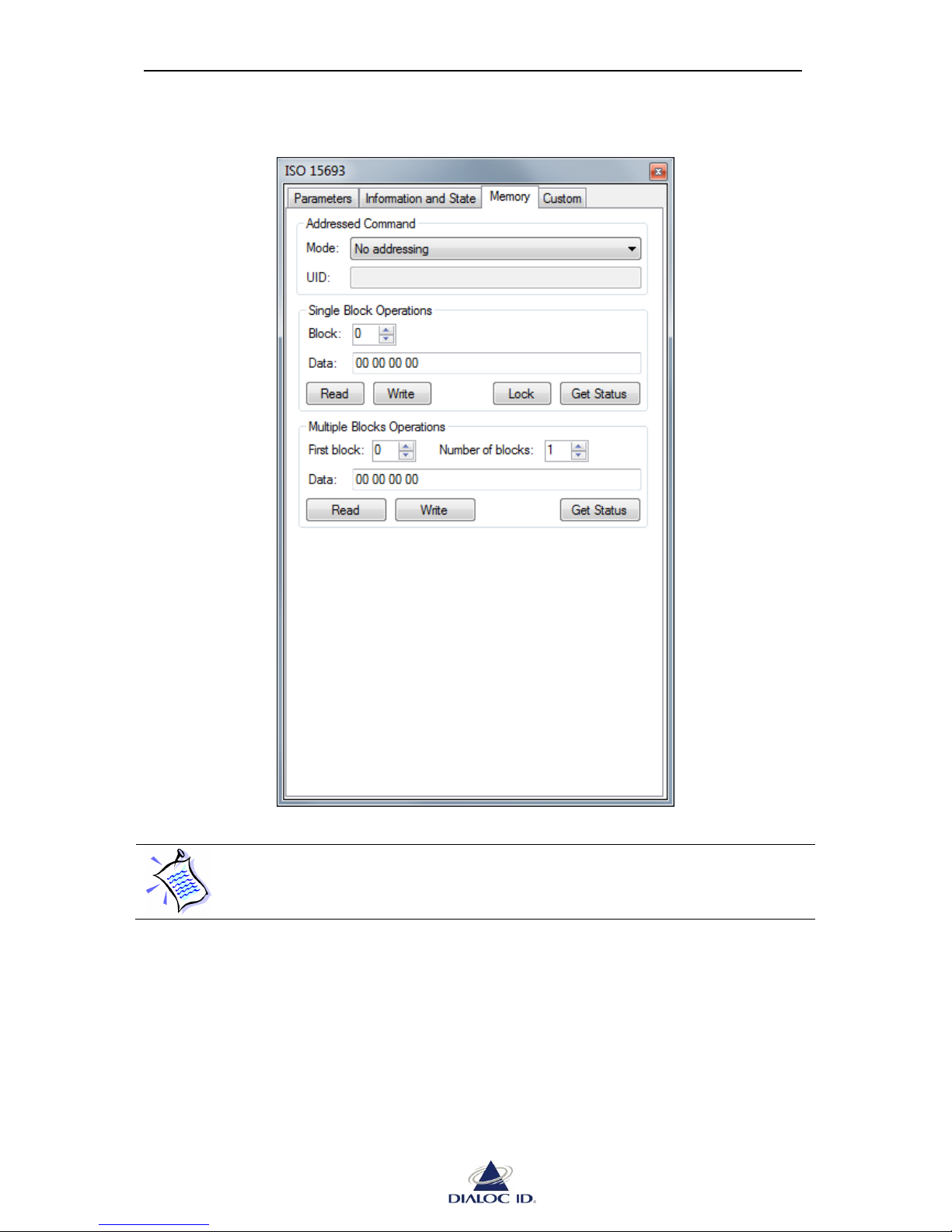
MCQ-PRO RFID Reader — Installation and Tuning Manual Version 1.00
Page 67 of 89
9.4.3 Memory tab
Figure 54: ISO 15693 panel (Memory tab)
Memory operations are dependant on the memory organization supported by
your ISO 15693 tags and require that you configure device’s radio as explained
in section 9.2.1.
Addressed Command
See section 9.2.2 for more information.
Page 68
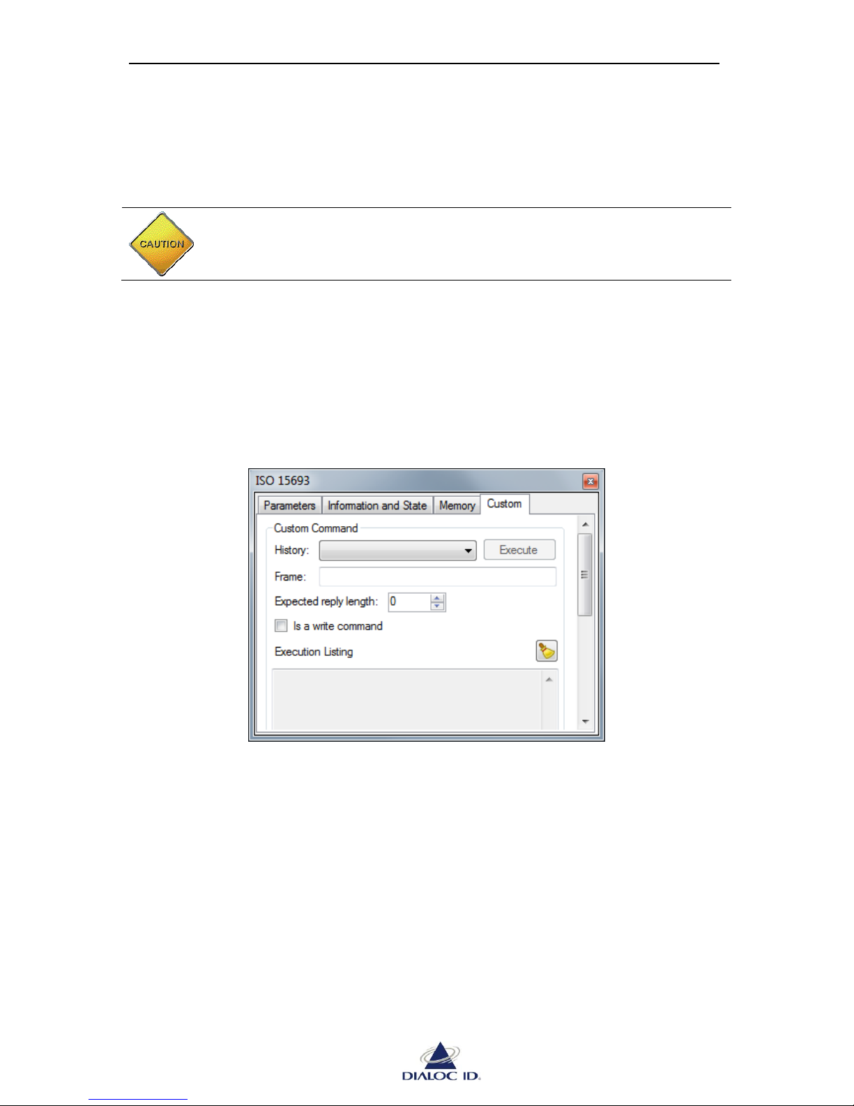
MCQ-PRO RFID Reader — Installation and Tuning Manual Version 1.00
Page 68 of 89
Single Block Operation
To perform a single block operation, place ISO 15693 tags in radio field, choose an
addressing mode, enter the block to use (decimal), enter optionally the data to write
(hexadecimal) and click the operation to perform.
CAUTION: Locked blocks cannot be unlocked.
Multiple Blocks Operation
To perform a multiple block operation, place ISO 15693 tags in radio field, choose an
addressing mode, enter the first block (decimal) and the number of blocks to use (decimal),
enter optionally the data to write (hexadecimal) and click the operation to perform.
9.4.4 Custom tab
Figure 55: ISO 15693 panel (Custom tab)
Custom Command
You can send any command directly to ISO 15693 tags by entering it in “Frame” field (as
hexadecimal bytes) and clicking “Execute”. Recent commands are displayed in “History” list.
Custom commands depend on tag manufacturer. See tag specifications for more information.
Page 69
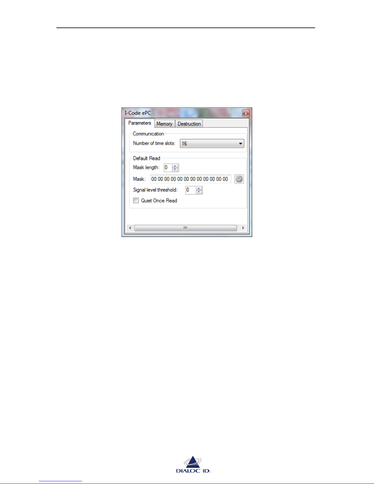
MCQ-PRO RFID Reader — Installation and Tuning Manual Version 1.00
Page 69 of 89
9.5 I-Code ePC
Open “I-Code ePC” panel by choosing “I-Code ePC” in the “Radio > Tag Parameters and
Commands” menu.
9.5.1 Parameters tab
Figure 56: I-Code ePC panel (Parameters tab)
Communication
“Number of time slots” list permits you to change the number of time slots used during
default read.
Default Read
To set a mask, select “Mask length” field and enter it in “Mask” field. During default read,
only tags whose ePC matches this mask will reply. A null value disables the mask.
“Signal level threshold” permits to report a tag only if its signal level is greater or equal to this
threshold during asynchronous read. All tags will be reported if the threshold is set to 0.
Check “Quiet Once Read” to request tags to stay quiet once read.
Page 70
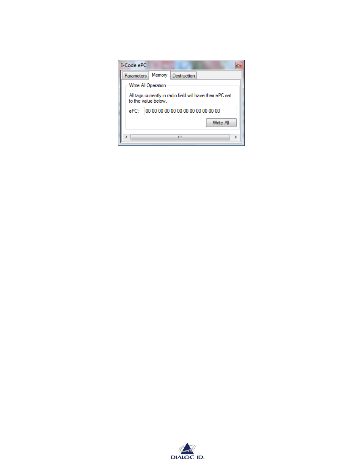
MCQ-PRO RFID Reader — Installation and Tuning Manual Version 1.00
Page 70 of 89
9.5.2 Memory tab
Figure 57: I-Code ePC panel (Memory tab)
Write All Operation
To write ePC of all tags currently in radio field, enter the code as 12 hexadecimal bytes in
“ePC” field and click “Write All”.
Page 71
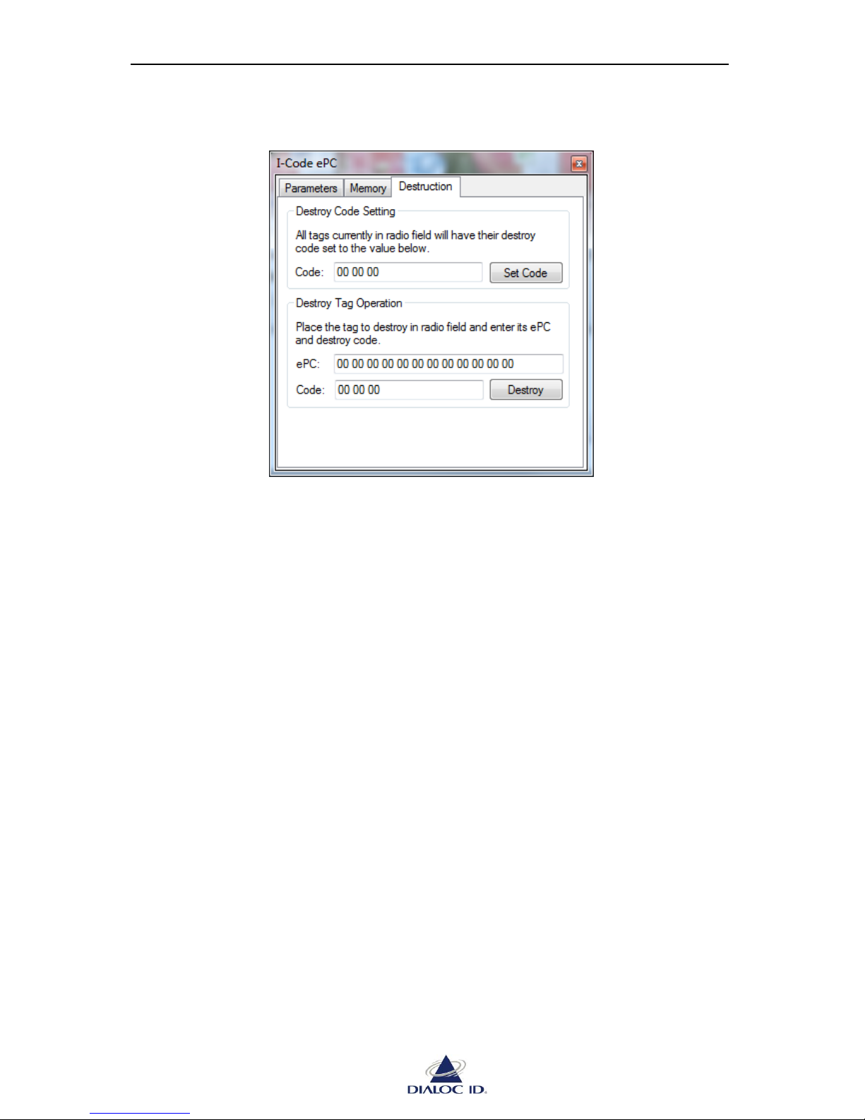
MCQ-PRO RFID Reader — Installation and Tuning Manual Version 1.00
Page 71 of 89
9.5.3 Destruction tab
Figure 58: I-Code ePC panel (Destruction tab)
Destroy Code Setting
To write destroy code of all tags currently in radio field, enter the code as 3 hexadecimal
bytes in “Code” field and click “Set Code”.
Destroy Tag Setting
To destroy tag currently in radio field, enter its ePC in “ePC” field and its destroy code in
“Code” field and click “Destroy”.
Page 72
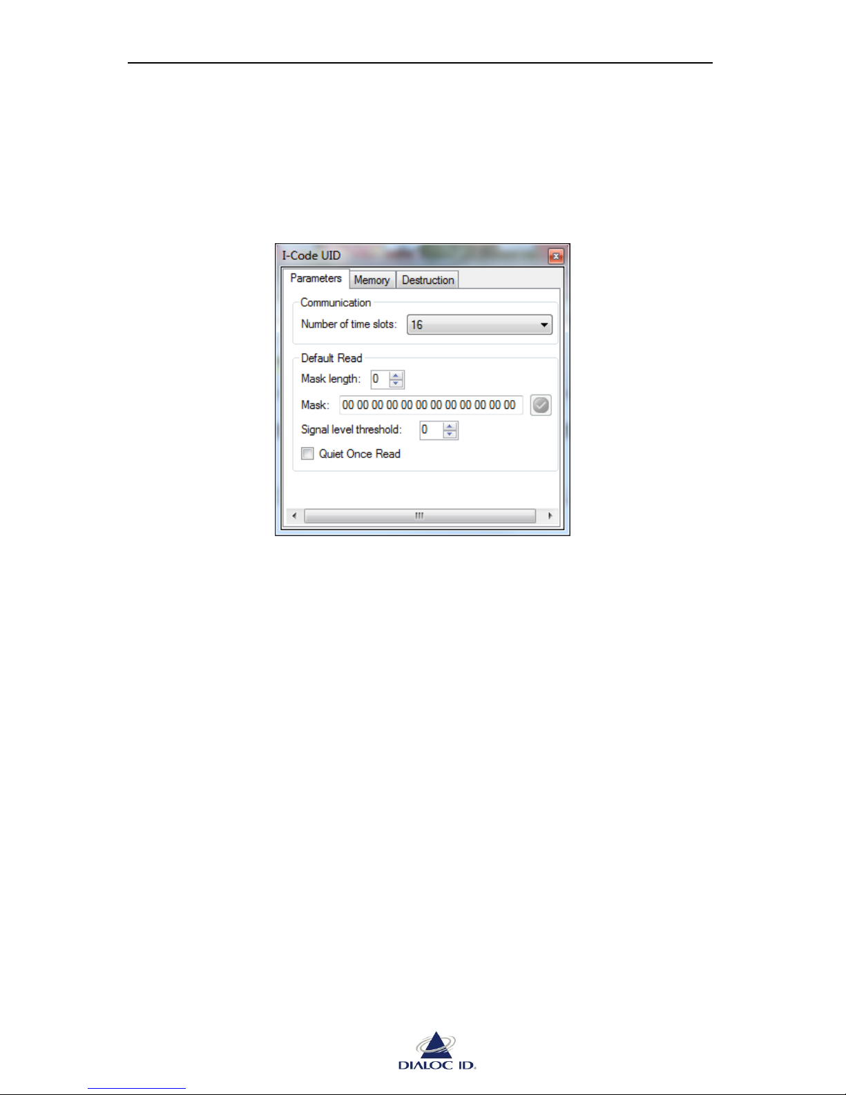
MCQ-PRO RFID Reader — Installation and Tuning Manual Version 1.00
Page 72 of 89
9.6 I-Code UID
Open “I-Code UID” panel by choosing “I-Code UID” in the “Radio > Tag Parameters and
Commands” menu.
9.6.1 Parameters Tab
Figure 59: I-Code UID panel (Parameters tab)
Communication
“Number of time slots” list permits you to change the number of time slots used during
default read.
Default Read
To set a mask, select the length in “Mask length” field and enter it in “Mask” field. During
default read, only tags whose ePC matches this mask will reply. A null value disables the
mask.
“Signal level threshold” permits to report a tag only if its signal level is greater or equal to this
threshold during asynchronous read. All tags will be reported if the threshold is set to 0.
Check “Quiet Once Read” to request tags to stay quiet once read.
Page 73
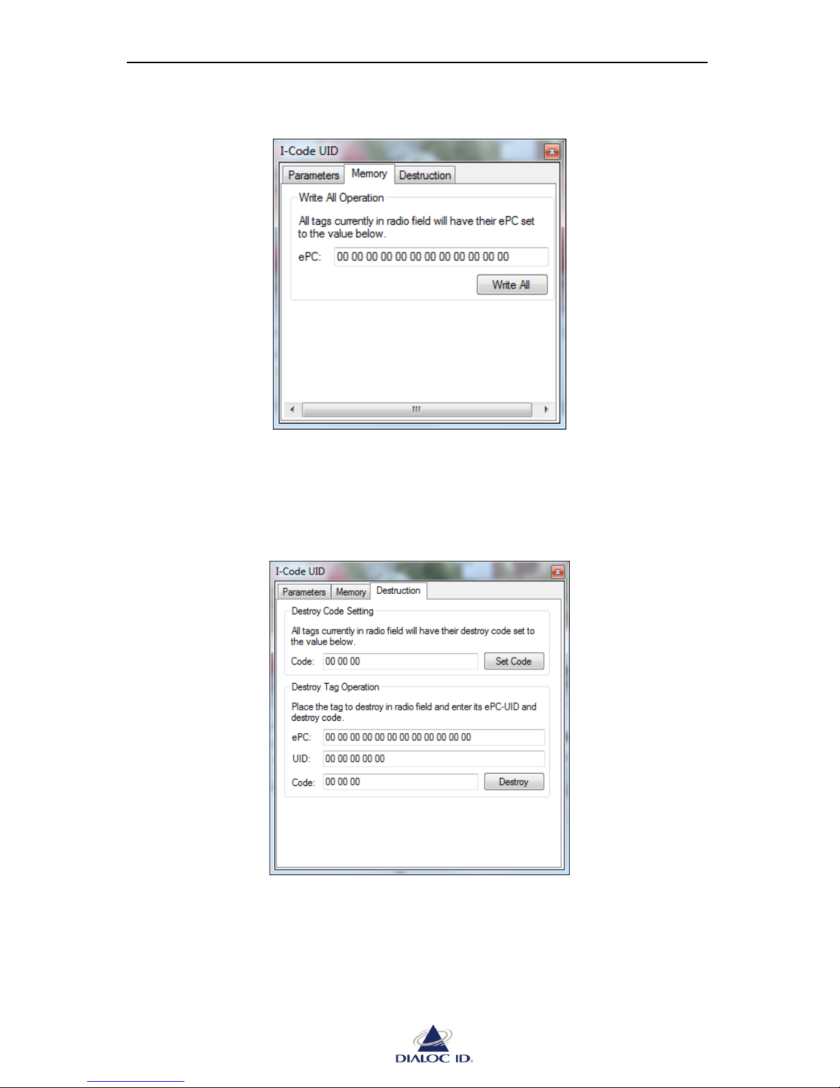
MCQ-PRO RFID Reader — Installation and Tuning Manual Version 1.00
Page 73 of 89
9.6.2 Memory Tab
Figure 60: I-Code UID panel (Memory tab)
Write All Operation
To write ePC of all tags currently in radio field, enter the code as 12 hexadecimal bytes in
“ePC” field and click “Write All”.
9.6.3 Destruction Tab
Figure 61: I-Code UID panel (Destruction tab)
Destroy Code Setting
To write destroy code of all tags currently in radio field, enter the code as 3 hexadecimal
bytes in “Code” field and click “Set Code”.
Page 74

MCQ-PRO RFID Reader — Installation and Tuning Manual Version 1.00
Page 74 of 89
Destroy Tag Setting
To destroy tag currently in radio field, enter its ePC/UID in “ePC”/”UID” fields and its
destroy code in “Code” field and click “Destroy”.
Page 75
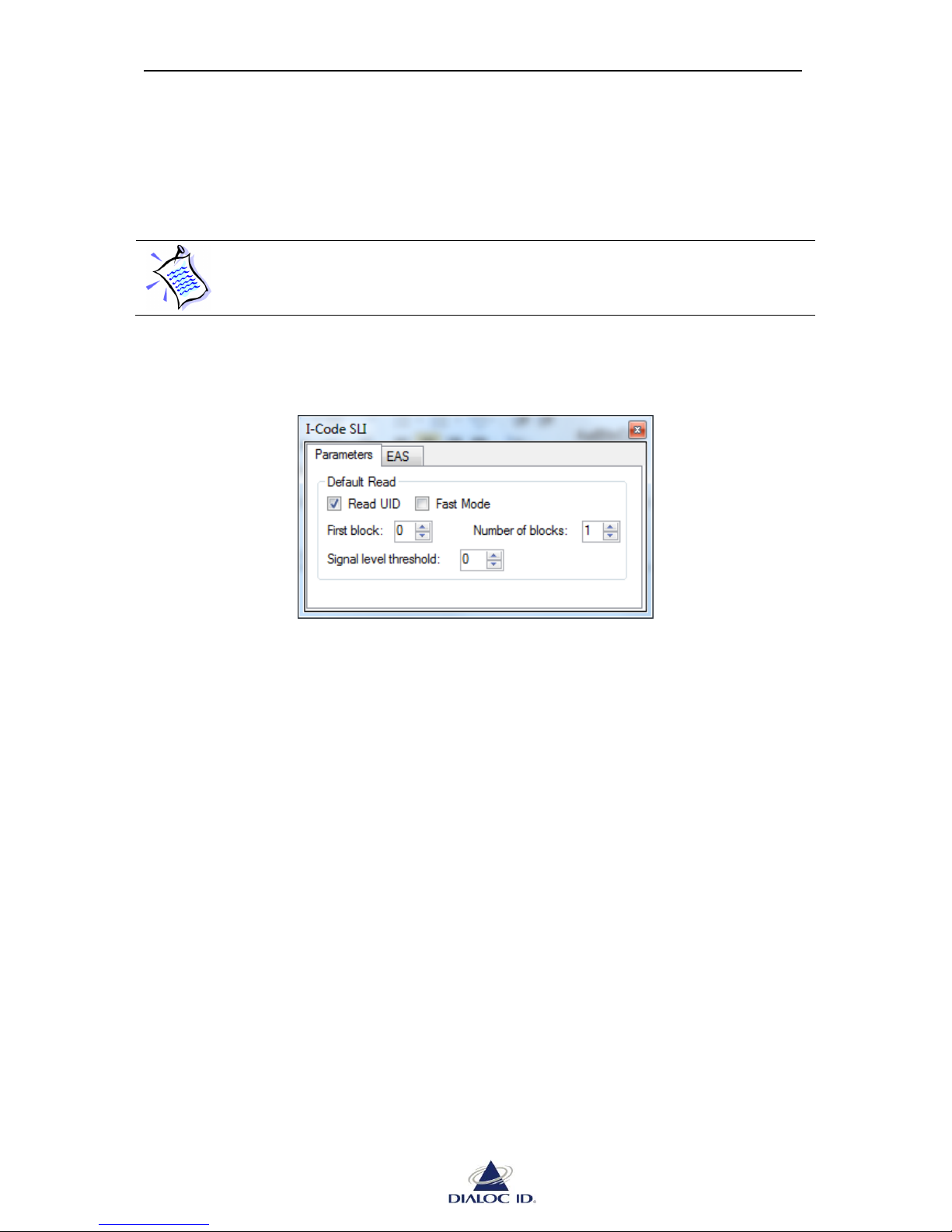
MCQ-PRO RFID Reader — Installation and Tuning Manual Version 1.00
Page 75 of 89
9.7 I-Code SLI (C370)
Open “I-Code SLI” panel by choosing “I-Code SLI” in the “Radio > Tag Parameters and
Commands” menu.
As I-Code SLI (C370) tags are ISO 15693 compliant, they support as well ISO
15693 parameters and commands (see section 9.4).
9.7.1 Parameters Tab
Figure 62: I-Code SLI panel (Parameters tab)
Default Read
During an I-Code SLI default read, tags memory and optionally UID can be read.
To read tags UID, check “Read UID”. The UID and then memory blocks will be reported
sequentially.
To select which part of the memory should be read, enter the first block in “First block”
(decimal) field and the number of blocks in “Number of blocks” (decimal). Memory blocks
are reported sequentially.
Check “Fast Mode” to specify whether to use memory inventory tag command (A0h) or fast
memory inventory tag command (A1h). See I-Code SLI specifications for more information.
“Signal level threshold” permits to report a tag only if its signal level is greater or equal to this
threshold during asynchronous read. All tags will be reported if the threshold is set to 0.
Page 76

MCQ-PRO RFID Reader — Installation and Tuning Manual Version 1.00
Page 76 of 89
9.7.2 EAS tab
Figure 63: I-Code SLI panel (EAS tab)
Addressed Command
See section 9.2.2 for more information.
Electronic Article Surveillance (EAS)
Click “Enable”/“Disable” to enable/disable EAS state.
Click “Lock” to prevent any future state change of EAS.
Click “Check” to get current state of EAS.
9.8 I-Code SLI-L/S (C370-L/S)
Open “I-Code SLI-L/S” panel by choosing “I-Code SLI-L/S” in the “Radio > Tag Parameters
and Commands” menu.
As I-Code SLI-L/S (C370-L/S) tags are ISO 15693 compliant, they support as
well ISO 15693 parameters and commands (see section 9.4).
9.8.1 Parameters Tab
Figure 64: I-Code SLI-L/S panel (Parameters tab)
Page 77
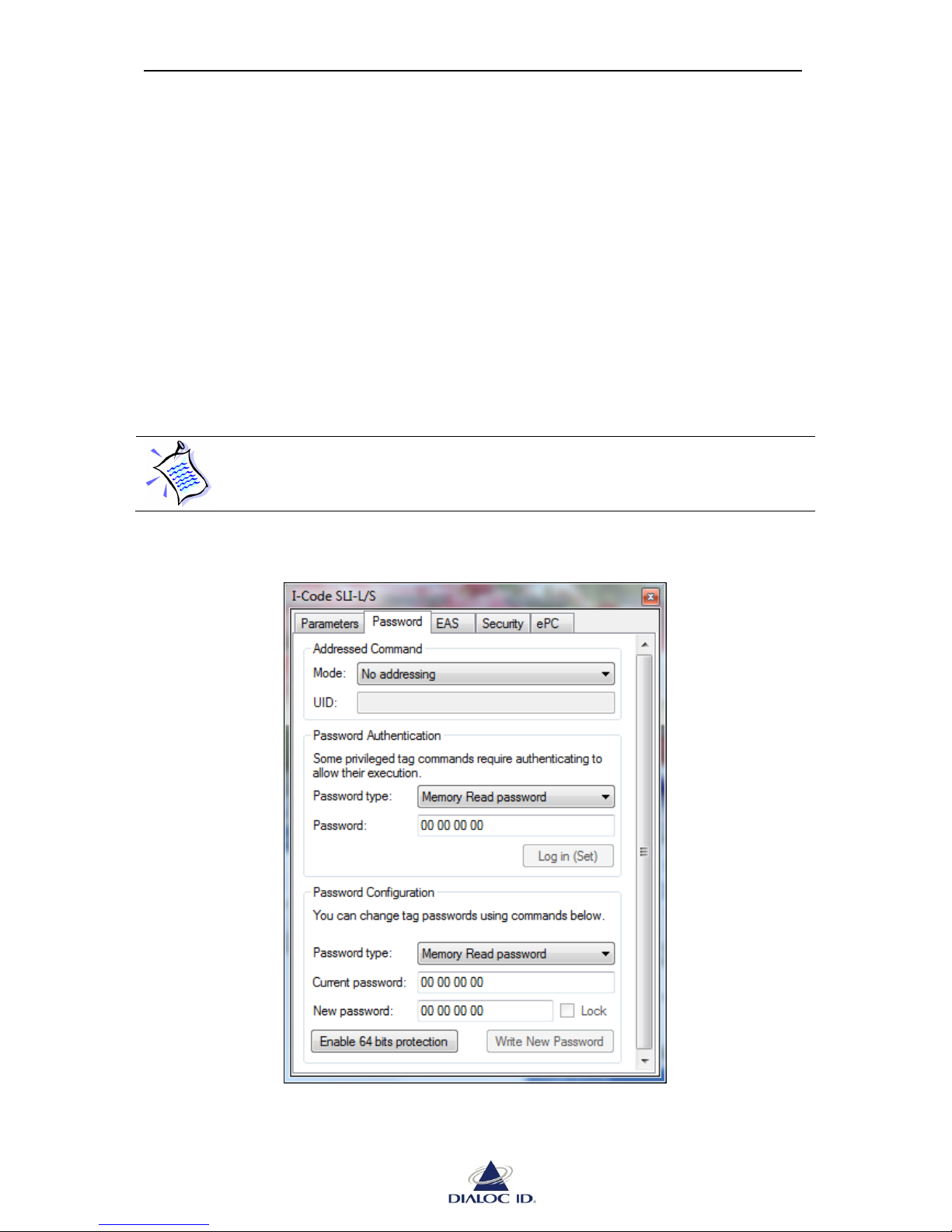
MCQ-PRO RFID Reader — Installation and Tuning Manual Version 1.00
Page 77 of 89
Default Read
During an I-Code SLI-L/S default read, tags memory and optionally UID can be read.
To read tags UID, check “Read UID”. The UID and then memory blocks will be reported
sequentially.
To select which part of the memory should be read, enter the first block in “First block”
(decimal) field and the number of blocks in “Number of blocks” (decimal). Memory blocks
are reported sequentially.
Check “Fast Mode” to specify whether to use page inventory tag command (B0h) or fast page
inventory tag command (B1h). See I-Code SLI-L/S specifications for more information.
“Signal level threshold” permits to report a tag only if its signal level is greater or equal to this
threshold during asynchronous read. All tags will be reported if the threshold is set to 0.
When attempting to read blocks of memory that belong to password protected
pages, and password has not been logged in first, block content is reported as
“XX XX XX XX”.
9.8.2 Password tab
Figure 65: I-Code SLI-L/S panel (Password tab)
Page 78
MCQ-PRO RFID Reader — Installation and Tuning Manual Version 1.00
Page 78 of 89
Addressed Command
See section 9.2.2 for more information.
Some password commands can be executed in addressed or selected modes only.
See I-Code SLI-L/S specifications for more information.
Password Authentication
Some I-Code SLI-L/S tag commands may require authenticating with a password.
To login in with a password, select its type in “Password type” list, enter the password as 4
hexadecimal bytes in “Password” field and click “Log in (Set)”.
I-Code SLI-L/S specification uses the term of “Setting password” instead of
“Logging in with password”. Do not confuse this with “Writing password”
below.
Password Configuration
To write a password, select its type in “Password type” list, enter its current value as 4
hexadecimal bytes in “Current password” field, enter its new value in “New password” field
and click “Write New Password”. Additionally, check “Lock” before clicking “Write New
Password” to write the password and prevent any future change.
To enable 64 bits protection, click “Enable 64 bits protection”. Both read and write passwords
must have been logged in first. See I-Code SLI-L/S specifications for more information.
CAUTION: Locked passwords cannot be unlocked and 64 bits protection mode
cannot be exited once entered.
Page 79
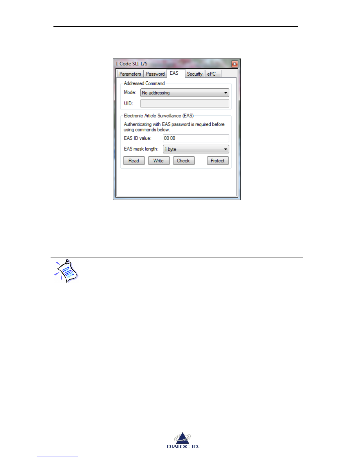
MCQ-PRO RFID Reader — Installation and Tuning Manual Version 1.00
Page 79 of 89
9.8.3 EAS tab
Figure 66: I-Code SLI-L/S panel (EAS tab)
Addressed Command
See section 9.2.2 for more information.
Electronic Article Surveillance (EAS)
You can manage other EAS features of I-Code SLI-L/S tags in “EAS” tab in “ICode SLI” panel (see section 0).
Before using those commands, you may have to authenticate with EAS password as explained
in section 9.8.2.
To read current EAS ID, click “Read”.
To write current EAS ID, enter its value as two hexadecimal bytes then click “Write”.
To check EAS state of a tag whose EAS ID matches a specific EAS ID mask, specify mask
length (1 or 2 bytes), enter mask value is “EAS ID value” field as one or two hexadecimal
bytes, then click “Check”.
To password protect EAS features, click “Protect”.
See I-Code SLI-L/S specifications for more information about EAS features.
Page 80
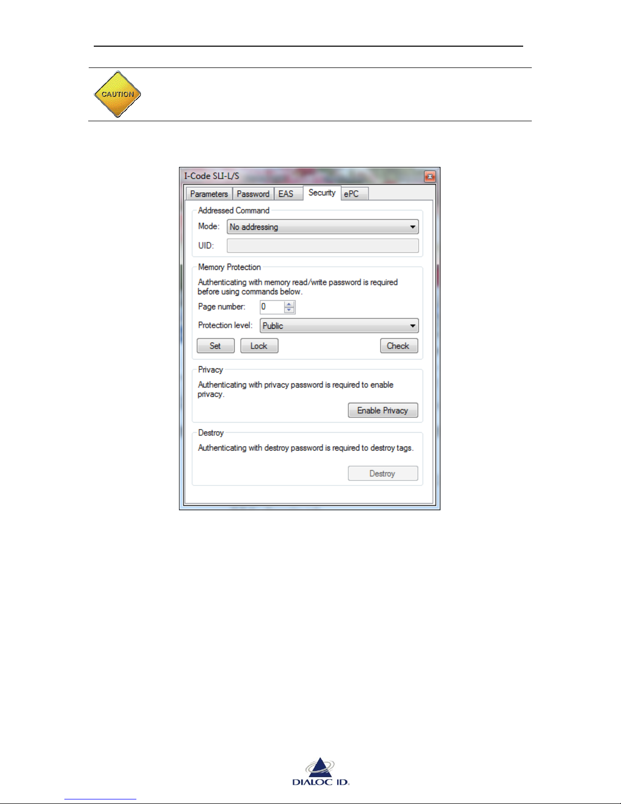
MCQ-PRO RFID Reader — Installation and Tuning Manual Version 1.00
Page 80 of 89
CAUTION: EAS password protection can not be disabled.
9.8.4 Security tab
Figure 67: I-Code SLI-L/S panel (Security tab)
Addressed Command
See section 9.2.2 for more information.
Destroy operation must be performed in selected or addressed mode.
Memory Protection
Before using those commands, you must authenticate with memory read or memory write
password as explained in section 9.8.2.
I-Code SLI-L/S memory can be protected at page level. Memory pages have a size of 4
blocks.
To password-protect a memory page, select its number, choose a protection level and click
“Set”.
To prevent any future state change of the password-protection of a page, click “Lock”.
Page 81
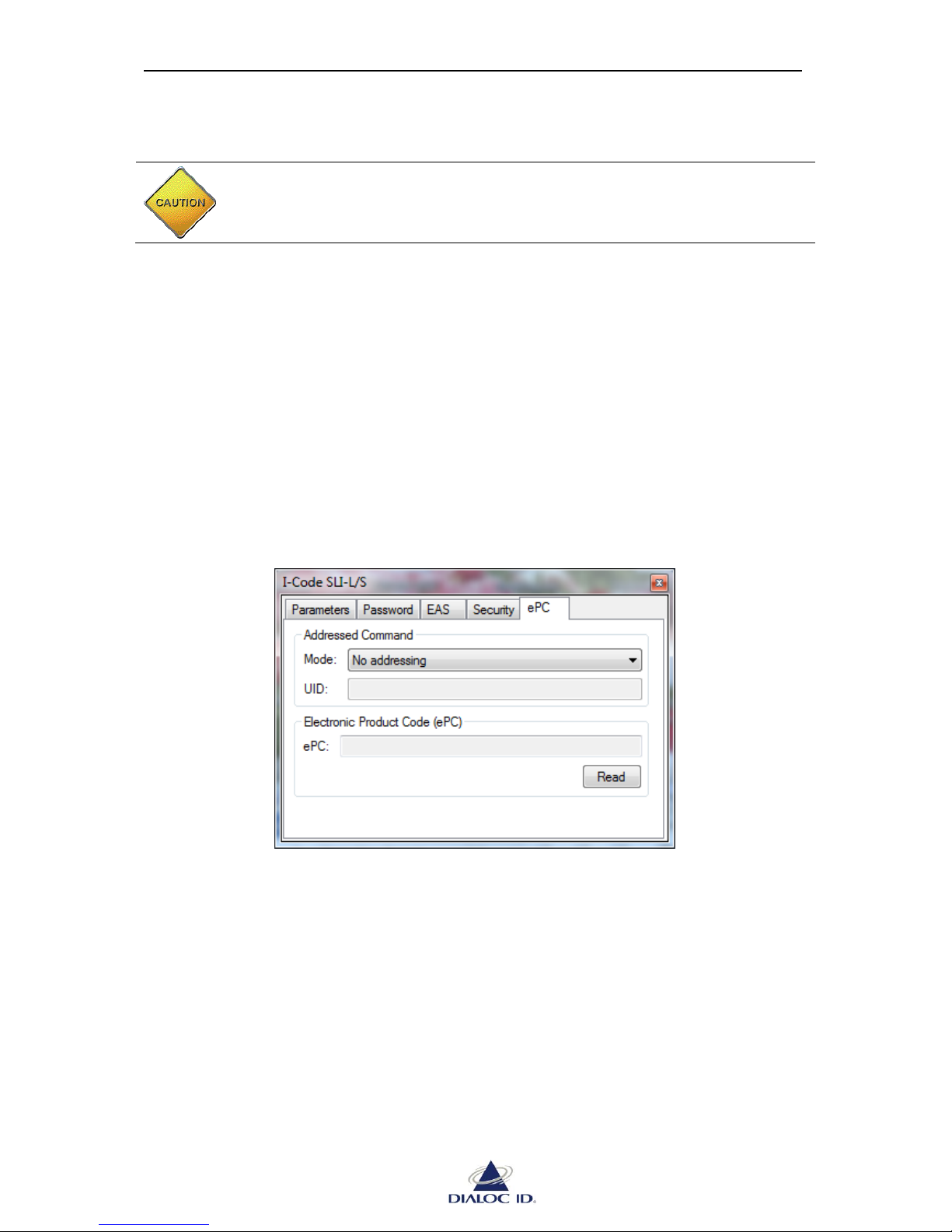
MCQ-PRO RFID Reader — Installation and Tuning Manual Version 1.00
Page 81 of 89
To check the password-protection state of a page, click “Check”.
CAUTION: Once locked, password-protection cannot be unlocked.
Privacy
To enable privacy mode, you must authenticate with privacy password as explained in section
9.8.2 and click “Enable privacy”. When in privacy mode, tag will not accept further
commands unless privacy password is logged in again.
Destroy
To destroy a tag, you must authenticate with destroy password as explained in section 9.8.2
and click “Destroy”. When destroyed, tag will not accept further commands again.
9.8.5 ePC tab
Figure 68: I-Code SLI-L/S panel (ePC tab)
Addressed Command
See section 9.2.2 for more information.
Electronic Product Code (ePC)
To read the ePC of a tag, click “Read”.
Page 82
MCQ-PRO RFID Reader — Installation and Tuning Manual Version 1.00
Page 82 of 89
You can write ePCs of I-Code SLI-L/S tags in “Memory” tab of “I-Code ePC”
panel (see section 0).
Page 83
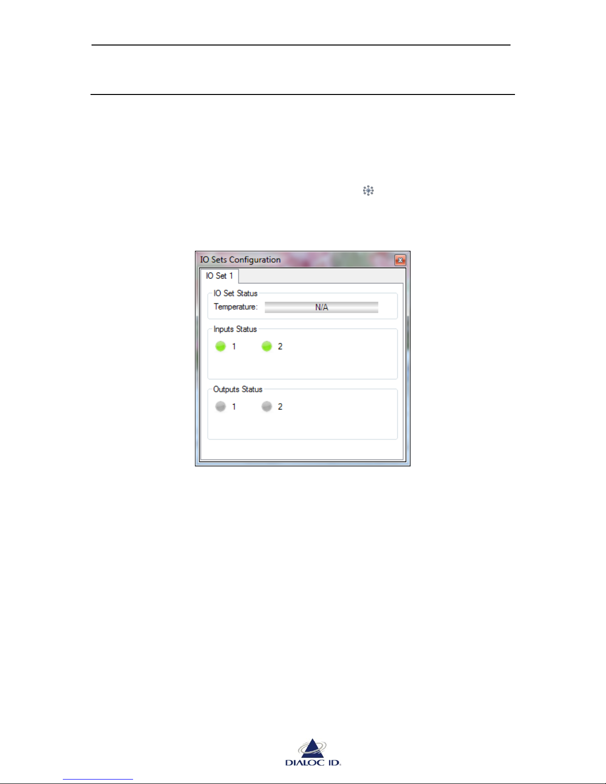
MCQ-PRO RFID Reader — Installation and Tuning Manual Version 1.00
Page 83 of 89
10 Using IO Sets
10.1 IO Sets Configuration
An IO Set is a group of inputs/outputs that you can use with your application.
10.1.1 ISO Set Status
Open “IO Sets Configuration” panel by clicking on the icon in the toolbar or by choosing
“IO Sets Configuration” in the “Radio” menu.
Figure 69: IO Sets Configuration panel
You can watch on this panel IO Set temperature and inputs status.
You can as well control outputs state by clicking on their LEDs.
Inputs are green when active and gray when inactive.
Outputs are red when active and gray when inactive. The output blinks if an overload is
detected.
10.2 Input trigger and Output feedback
You can start default read using an input trigger and get feedback when a tag is read with the
output feedback.
See section 8.2.4 to know how to enable those read mode options.
Page 84

MCQ-PRO RFID Reader — Installation and Tuning Manual Version 1.00
Page 84 of 89
11 Standalone Mode
Standalone mode makes it possible to use the device without the need for a host to control it.
In this case, only the tag reading operation is available.
When standalone mode is activated, the device automatically loads from NVRAM its last
saved radio configuration upon start-up and initiates a read session. Each time a read event
occurs, the device sends a frame over its serial port.
A watchdog can also be activated. In this case, a customizable frame is sent periodically over
the serial port to indicate the device is operating properly.
11.1 Standalone mode configuration
Open “Standalone Mode Configuration” panel by clicking on the icon in the toolbar or by
choosing “Standalone Mode Configuration” in the “Device” menu.
11.1.1 Message format
A message frame is a sequence of bytes composed of several optional and customizable
ASCII fields.
For all radio events but “No Read” event, the frame has the following canonical format:
<Header><Timestamp + Suffix><Radio ID + Suffix><Event Type><Channel Number +
Suffix><Tag Type><Data (n digits)><Checksum><Footer>
Example:
Frame’s bytes as sent by device:
3C 32 30 30 37 2D 31 32 2D 30 34 20 31 32 3A 30 35 3A 34 35 3B 30 3B 54 41 47
52 45 41 44 3B 31 3B 49 43 4F 44 45 3B 43 44 45 46 30 31 32 33 34 35 36 37 38 39
41 42 32 31 3E 0D 0A
Frame’s bytes interpreted as a sequence of ASCII characters:
<2007-12-04 11:52:57;0;TAGREAD;1;ICODE;CDEF0123456789AB23>\0D\0A
“\0D\0A” represents carriage return (0x0D) and line feed (0x0A) non-printable characters.
The checksum is a byte value computed by applying exclusive-or (XOR) operation on all
frame's bytes sent before the checksum. In this example, it is equal to 0x23 in hexadecimal.
If no tag has been read (“No Read” event), the frame has the following canonical format:
<Header><Timestamp + Suffix><Radio ID + Suffix><Event Type><No Read
Description><Checksum><Footer>
Page 85
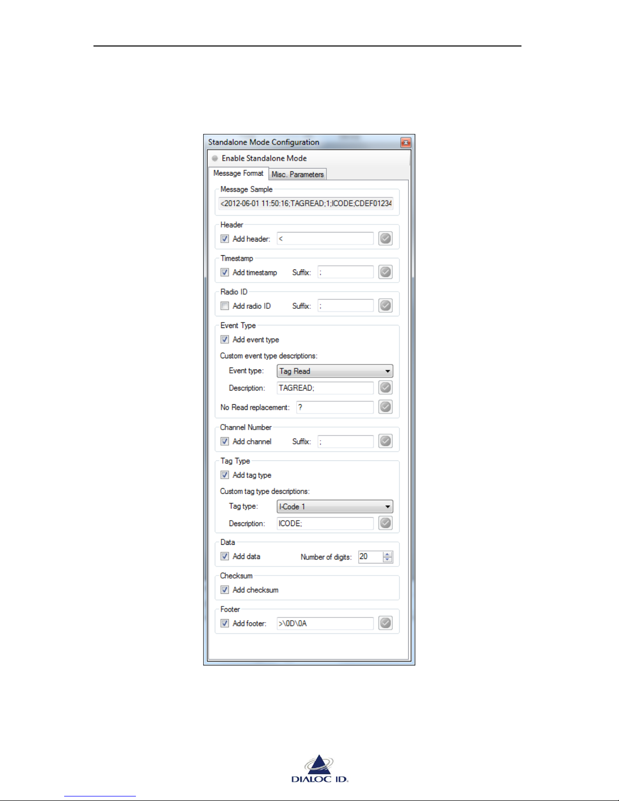
MCQ-PRO RFID Reader — Installation and Tuning Manual Version 1.00
Page 85 of 89
You can configure format of the message frame sent on serial port when a tag is read on
“Message Format” tab.
Figure 70: Standalone Mode panel (Message Format tab)
Page 86
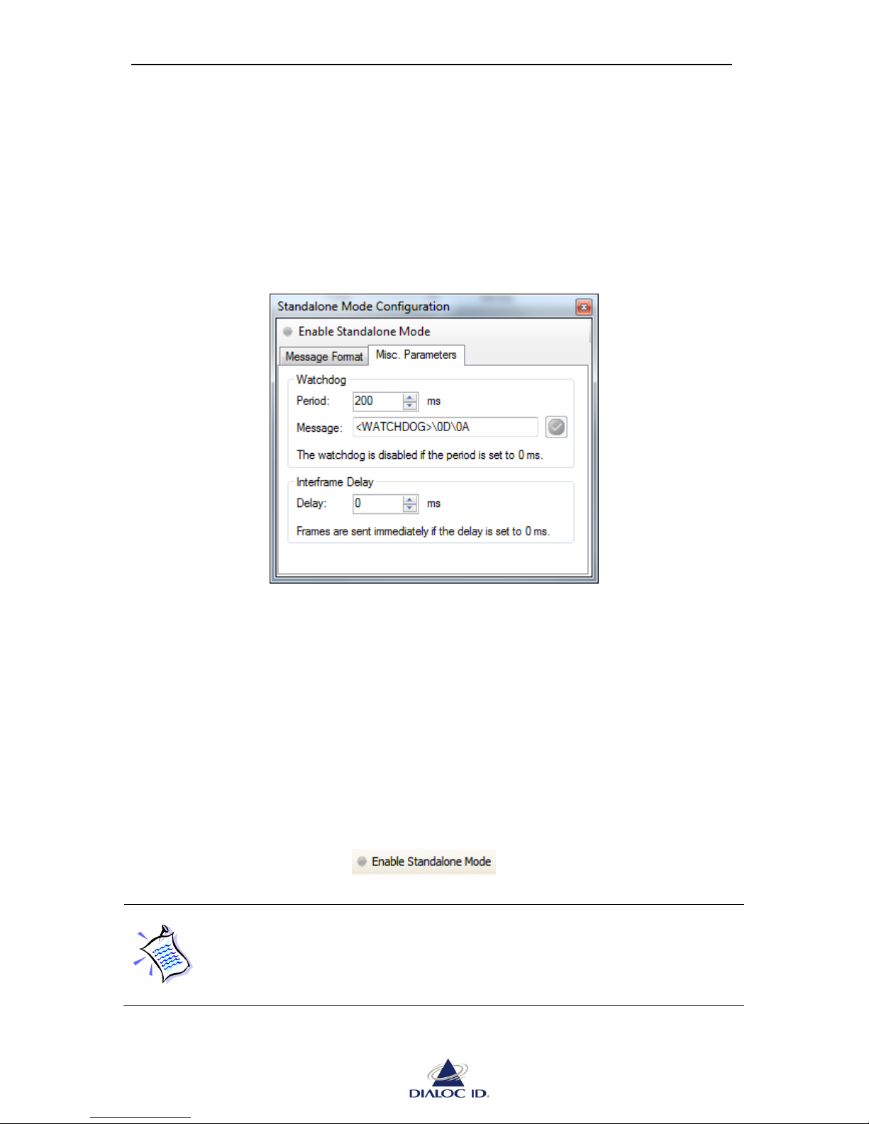
MCQ-PRO RFID Reader — Installation and Tuning Manual Version 1.00
Page 86 of 89
Use “Message Format” tab checkboxes to choose which fields should be sent.
You can customize text fields by entering the text of your choice as ASCII beside
checkboxes. To enter a non-printable character, enter “\xx” (without quotes) where xx is the
ASCII code of the character as a hexadecimal byte.
11.1.2 Miscellaneous Parameters
This tab contains various standalone mode parameters.
Figure 71: Standalone Mode panel (Misc Parameters tab)
Watchdog
The watchdog permits sending periodically a custom frame on serial port.
You can configure the period used and the message to send in “Watchdog”.
Interframe Delay
If the device in standalone mode is connected to a slow legacy system, it may be necessary to
slow down frame rate to avoid flooding it.
You can configure the delay between each frame sent by device in “Interframe Delay”.
11.2 Enabling standalone mode
To enable standalone mode, click button in embedded toolbar of
“Standalone Mode Configuration” panel. Click this button again to disable standalone mode.
In standalone mode, the device loads radio configuration from its non-volatile
memory (NVRAM) when it is turned on. Consequently, you should save current
radio configuration to NVRAM before enabling standalone mode. Dialoc ID
MCQ-Pro proposes you to do so when enabling standalone mode. See section 0
to perform this operation manually.
Page 87
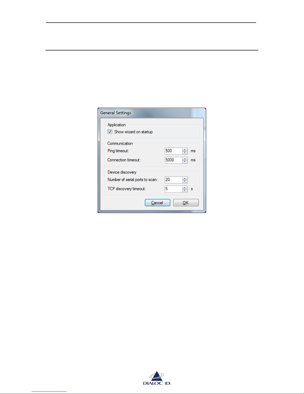
MCQ-PRO RFID Reader — Installation and Tuning Manual Version 1.00
Page 87 of 89
12 Other Topics
12.1 General Settings
Open “General Settings” window by choosing “General Settings…” in the “MCQ-Pro” menu.
This window permits configuring general settings of DIALOC ID MCQ-Pro.
Figure 72: General Settings window
Application
Check “Show wizard on startup” to show wizard when DIALOC ID MCQ-Pro starts up.
Communication
Before attempting to connect to a TCP/IP device, DIALOC ID MCQ-Pro tries to ping it. If
pinging timeouts, connecting will not be attempted. You can define in “Ping timeout” field
the time in milliseconds to wait before aborting the connection attempt.
You can define in “Connection timeout” field the maximum time in milliseconds to wait for
an answer from device (timeout).
Device discovery
To avoid discovery being too long, DIALOC ID MCQ-Pro limits the number of serial ports to
scan and the time to wait for a heartbeat on the TCP/IP network (see section 6.3.1).
You can define in “Device discovery” fields the limits used by DIALOC ID MCQ-Pro.
Page 88
MCQ-PRO RFID Reader — Installation and Tuning Manual Version 1.00
Page 88 of 89
12.2 Analog signal capture
Signal Capture permits studying internal In-Phase and Quadrature signals of device’s radio.
Open “Analog Signal Capture” panel by choosing “ Signal Capture” in the “Radio” menu.
12.2.1 Capturing signal
Signal capture requires a very high amount of data to be transferred each second.
Consequently, you should connect on device’s Ethernet interface before
capturing signal.
To capture and study the analog signal on a specific channel:
1. Define RF channels configuration (see section 7 for more information).
2. Click button in the toolbar to turn the radio field on.
CAUTION: Make sure an antenna is connected to channels you use before
turning the radio field on; otherwise it may severely damage the device.
3. Choose a sample rate and define capture and display settings (see next section).
4. Click to begin signal capture.
If the radio field is turned off, DIALOC ID MCQ-Pro will ask you to turn it on;
click “OK” to accept. Again, make sure an antenna is connected to the channel
before accepting.
5. Place a tag in the radio field if you have enabled “Wake Up Tags” capture setting.
6. Click button in the toolbar when you are finished reading. You may
want to turn the radio field off as well by clicking button.
Page 89
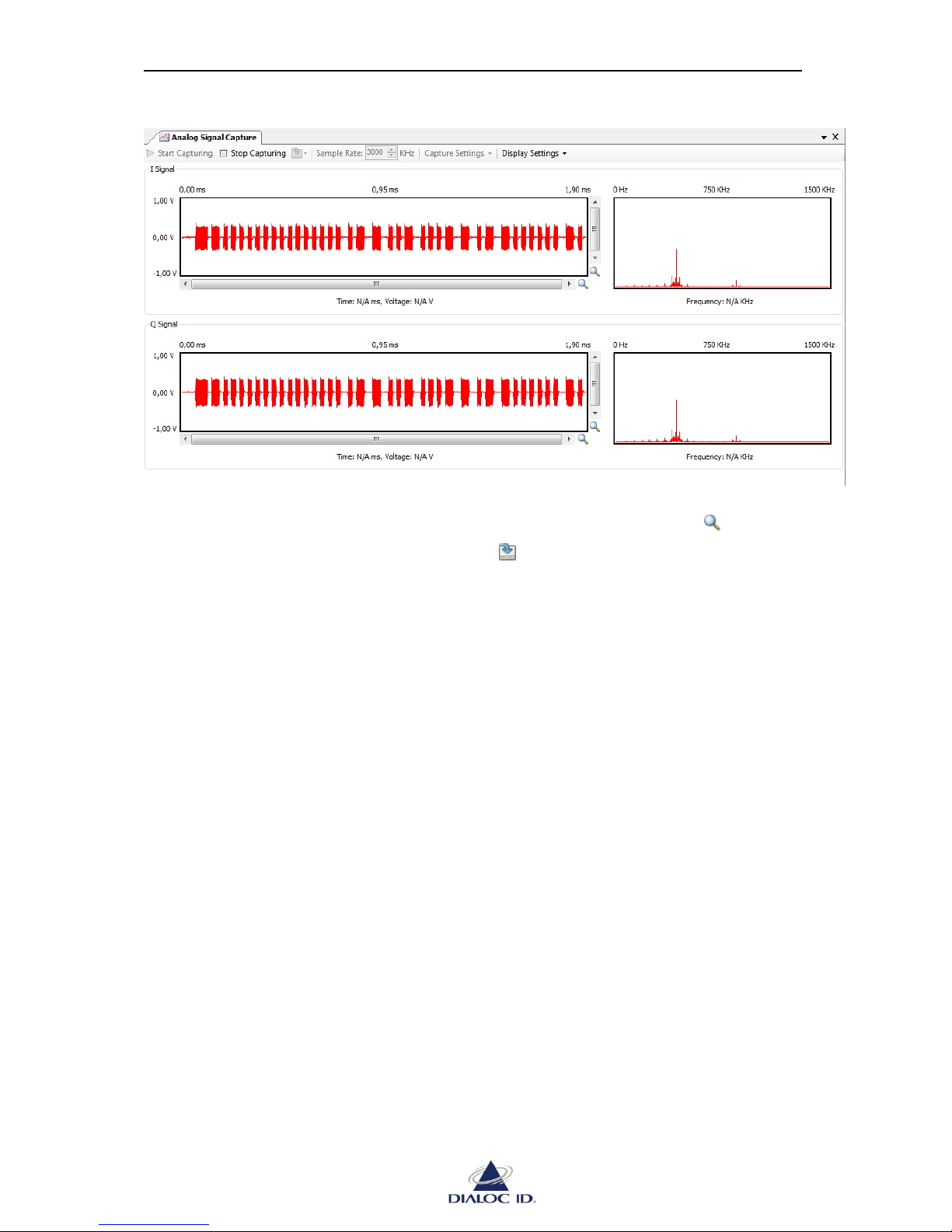
MCQ-PRO RFID Reader — Installation and Tuning Manual Version 1.00
Page 89 of 89
Figure 73: Analog Signal Capture
The left part of the panel displays signal on time domain; the right part displays signal on
frequency domain. You can move and zoom in time graph using scrollbars and buttons.
You can save capture data in a CSV file using the drop down menu.
12.2.2 Capture and Display settings
Capture settings:
“I Signal” (In-Phase signal) and “Q Signal” (Quadrature signal) can be both captured
or not.
“Wake Up Tags” wakes-up tags in radio field before capturing and permits visualizing
their replies. Disable this setting in order to visualize background noise.
Display settings:
“Auto Scale FFT Graphs” automatically scales FFT graph on amplitude axis. This
option is especially useful when “Wake Up Tags” setting is disabled.
 Loading...