

Page 1
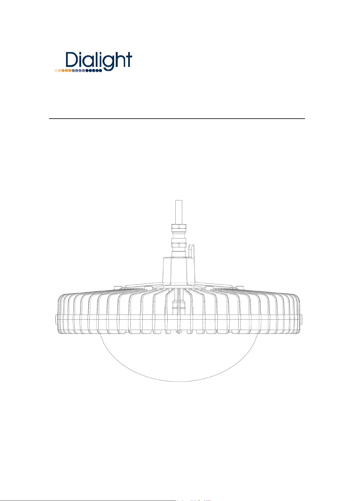
INSTALLATION AND MAINTENANCE MANUAL
DUROSITE
Document No: 9100-127-1485-99 Rev A
TM
SERIES LED LOW BAY
February 2011
Model Versions
LBW-XXXX-EU
Page 2
Document No: 9100-127-1485-99 Rev A
1: Introduction
This Low Bay light is designed for illumination of industrial locations. It uses the latest in solid state
lighting technology for long life, low maintenance, and high efficiency.
The unique optical design focuses light downward to where it is needed, giving improved efficiency
over conventional HID, HPS and Induction luminaires.
An internal power-factor-corrected switch-mode supply allows it to be used at a nominal
230/240VAC, 50/60Hz AC supply without any variation in light output.
• THIS LUMINAIRE IS IP66 RATED AND IS SUITABLE FOR INDOOR AND
OUTDOOR USE.
Note: Save these instructions for future reference.
2: Installation
Warning:
To avoid the risk of fire, explosion, or electric shock, this product should be installed, inspected,
and maintained by a qualified electrician only, in accordance with all applicable electrical codes.
Warning:
To avoid electric shock:
• Be certain electrical power is OFF before and during installation and maintenance.
• Luminaire must be connected to a wiring system with an equipment-grounding conductor.
Warning:
To avoid premature failure and to maintain continuous operation:
• Make sure the supply voltage is the same as the rated luminaire voltage.
• Do not install where the ambient temperature exceeds the marked operating temperatures.
For supply connections, use suitable 1.5mm2cable rated for 230/240V and at least 90ºC.
Recommended mounting height: 3 to 6 metres
Note: Lower mounting heights affect the overall coverage area but increase the light levels on the
targeted areas.
Page 2 of 5
Exning Road, Newmarket, Suffolk, CB8 0AX, UK
Tel: +44 (0) 1638 666541 Fax: +44 (0) 1638 561735 www.dialight.com
Page 3
Document No: 9100-127-1485-99 Rev A
Pendent Mount Installation Steps:
• For maximum long term reliability and light output, the light must be installed in free air.
• The Low Bay fixture design incorporates an over-temperature control circuit that reduces
input power should internal temperatures reach a maximum level. As a result, light output
may be reduced.
• The Low Bay fixture is fitted with a 3 metre long cable that can be extended if required.
• Eyebolts or other suitable fixings with an M6 thread can be secured to the rear of the High
Bay fixture for pendent mounting.
Stirrup Mounting
• When the Low Bay fixture is purchased with the optional ‘Stirrup Bracket’, the luminaire
must be installed in free air.
• The ‘Stirrup Bracket’ is fixed into place by the 2 bolts along the side of the light fixture,
when secured into the desired position the 2 bolts should be tightened to 8.0 – 10.0Nm.
Electrical Connection
• Note: Proper electrical and installations of extension should be carried out by a qualified
electrician.
• Connect power cable conductors as follows:
o GREEN/YELLOW wire connects to Safety Ground.
o BLUE wire connects to Neutral
o BROWN wire connects to Live
• Restore power and verify operation.
Interfacing to a PIR or Occupancy Sensor
:
The Dialight Low Bay fixture is ideally suited for control by an occupancy sensor in order to
maximize energy savings based on its instant-on behavior and low power consumption.
Instructions for connecting the High Bay fixture to an occupancy sensor are listed below.
Warning:
To be installed and/or used in accordance with appropriate electrical codes and regulations.
Warning:
Controlling a load in excess of the specified ratings of the occupancy sensor could damage the unit
and pose risk of fire, electric shock, personal injury, or death. Check load ratings to determine the
unit’s suitability for your application.
NOTE: See PIR/Occupancy sensor installation instructions for additional information.
1) WARNING: TO AVOID FIRE AND ELECTRICAL SHOCK, TURN OFF POWER AT
CIRCUIT BREAKER OR FUSE AND TEST THAT THE POWER IS OFF BEFORE
WIRING.
Page 3 of 5
Exning Road, Newmarket, Suffolk, CB8 0AX, UK
Tel: +44 (0) 1638 666541 Fax: +44 (0) 1638 561735 www.dialight.com
Page 4
Document No: 9100-127-1485-99 Rev A
2) Install occupancy sensor as per sensor instructions to provide desired coverage of area.
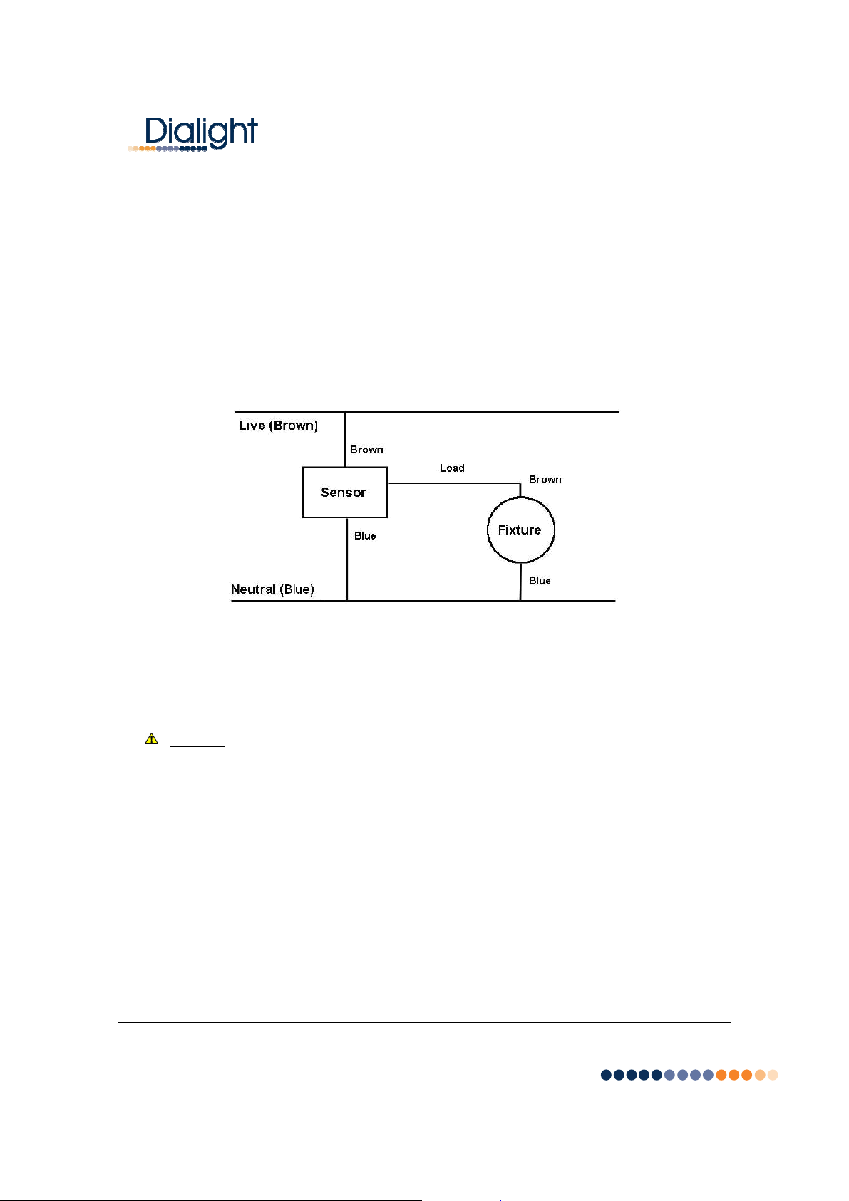
3) Connect luminaire wires per wiring diagram as follows: Brown lead to load of the
occupancy sensor, Blue lead to the Line (Neutral), Green/Yellow lead to Earth Ground.
Multiple fixtures may be connected to a sensor, as long as the rated load of the sensor is
not exceeded.
4) Restore power at circuit breaker or fuse.
5) Verify operation of system. If the light will not turn on, check the operation of the fixture
and sensor individually, and check that the wiring is done correctly. If the light will not turn
off or turns off and on quickly, see the sensor’s installation instructions for further guidance.
3: Maintenance
• To avoid personal injury, disconnect power to the light and allow the unit to cool down
before performing maintenance.
Warning: No user serviceable parts inside of fixture. Risk of electric shock. Removal of the
lens will void the warranty.
The lens could be cleaned periodically as needed to ensure continued photometric
performance. Clean the lens with a damp, non-abrasive, lint-free cloth. If not sufficient, use
mild soap or a liquid cleaner. Do not use an abrasive, strong alkaline or acid cleaner as
damage may occur.
During any maintenance inspect the cooling fins on the luminaire to ensure that they are
free of any obstructions or contamination (i.e. excessive dust build-up). Clean with a nonabrasive cloth if needed.
Page 4 of 5
Exning Road, Newmarket, Suffolk, CB8 0AX, UK
Tel: +44 (0) 1638 666541 Fax: +44 (0) 1638 561735 www.dialight.com
Page 5
Document No: 9100-127-1485-99 Rev A
4: Specifications
Nominal AC Supply Voltage 230/240VAC, 50/60Hz
ower consumption 80W nominal
P
Operating temperature range -40°C to +60°C [-40°F to +140°F]
Power factor >0.9
ATHD <15%
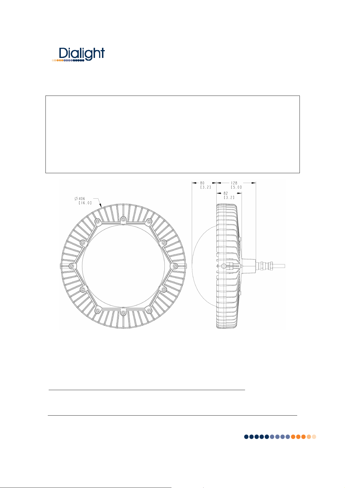
Dimensions (Height x Diameter) 20.3cm x 40.6cm [8” x 16”]
Weight 8.2 kg [18 lbs]
DIMENSIONS ARE FOR REFERENCE ONLY.
All statements, technical information and recommendations contained herein are based on information and
tests we believe to be reliable. The accuracy or completeness thereof is not guaranteed. In accordance with
Dialight Corporation “Terms and Conditions of Sale”, and since conditions of use are outside our control, the
purchaser should determine the suitability of the product for his intended use and assumes all risk and liability
whatsoever in connection therewith.
REV. ECO No. DRN CHK APP QA CM DATE
A ---- KLJ DW KH RL JB 5-4-11
Page 5 of 5
Exning Road, Newmarket, Suffolk, CB8 0AX, UK
Tel: +44 (0) 1638 666541 Fax: +44 (0) 1638 561735 www.dialight.com
 Loading...