

Page 1
Version 1.0
Doc. nr.: DI-C-01-008.5
InstructionsforUse
AGE Reader mu Contents
User Manual
Contents
1 Introduction .......................................................................................................... 1
2 Intended use ........................................................................................................ 2
2.1 Conditions for which the device is not to be used ....................................................... 2
3 Warnings and precautions ................................................................................... 3
4 Description of the AGE Reader mu ...................................................................... 4
5 Installing the AGE Reader mu ............................................................................. 5
6 Instructions for use ............................................................................................... 6
6.1 Starting the AGE Reader mu ....................................................................................... 6
6.2 Main screen ................................................................................................................. 7
6.3 Measurement............................................................................................................... 8
6.4 Settings screen .......................................................................................................... 15
7 Background on AGE values ............................................................................... 19
8 Cleaning & maintenance .................................................................................... 22
8.1 Cleaning instructions ................................................................................................. 22
8.2 Maintenance instructions ........................................................................................... 22
9 Problems & solutions ......................................................................................... 23
9.1 Power supply problems ............................................................................................. 23
9.2 Problems during operation ........................................................................................ 23
10 Technical specifications ................................................................................... 24
11 Marking on the AGE Reader mu ...................................................................... 25
11.1 The rear label ............................................................................................................ 25
11.2 The serial label .......................................................................................................... 26
11.3 Power button ............................................................................................................. 27
11.4 Packaging label ......................................................................................................... 28
12 Spare parts & accessories ............................................................................... 29
12.1 Spare Parts................................................................................................................ 29
13 Liability & warranty ........................................................................................... 30
13.1 Liability....................................................................................................................... 30
13.2 Warranty .................................................................................................................... 30
13.3 Declaration of Conformity .......................................................................................... 30
14 Electromagnetic compatibility .......................................................................... 31
14.1 Essential performance ............................................................................................... 31
14.2 Electromagnetic emissions ........................................................................................ 31
14.3 Electromagnetic immunity ......................................................................................... 32
14.4 Distances between RF equipment ............................................................................ 34
Page 2

AGE Reader mu Introduction
User Manual
1
1 Introduction
AGEs play a pivotal role in the development of chronic age-related diseases such
as diabetes, renal failure and cardiovascular disease. The level of AGEs in longlived tissues (not in blood!) serves as a memory of glycometabolic and oxidative
stress and is a valuable predictor of cardiovascular complications.
Until now it has been complicated to measure tissue AGEs in patients because
existing methods are expensive, time consuming, lack specificity, are poorly
reproducible and/or are invasive. The AGE Reader mu is the answer to the need for
measuring AGEs without the disadvantages of the existing methods. This state of
the art device provides a simple non-invasive solution which allows users to
determine the AGE level within 12 seconds. The information from the AGE Reader
can assist physicians in focusing treatment on patients with the highest risk of
complications. This includes patients suffering from diabetes mellitus, renal failure
but also acute disorders like acute coronary syndromes and sepsis. Moreover it is
an excellent tool for researchers in various fields.
The AGE Reader mu was developed and is being commercialized by DiagnOptics
Technologies B.V, an innovative medical technology company in the Netherlands.
This user manual provides the instructions for use of the AGE Reader mu.
DiagnOptics Technologies B.V
AGE Reader mu Intended use
User Manual
2
2 Intended use
When used as intended, the AGE Reader mu non-invasively gives an evaluation of
Advanced Glycation End products (AGEs) in tissue. Clinical evidence shows that
AGE levels may assist the physician in clinical practice to assess the risk of
cardiovascular disease.
The AGE Reader mu is intended to be used by trained personnel to assess the
level of auto fluorescence in human skin. Users are expected to be familiar with
standard medical practices as required for patient monitoring.
All instructions, procedures and information in this user manual and on the labelling
on the device are to be regarded as the “Intended Use” and will fully inform the user
about the correct and safe use and installation of the AGE Reader mu.
AGE measurements should be performed directly on intact healthy skin on the inner
side of the dominant lower forearm. The skin at the measuring area should be
healthy, homogeneous and free of birthmark, tattoos or excessive hair growth and
without recent exposure to skin creams or any substance that may have fluorescent
properties. Self-tanning agents should not be used for at least 2 days before
measurement. Sun-blockers and other skin care products should be removed
before measurement.
Pigmented skin
The device and its software have been validated in patients with skin reflection >8%
(Fitzpatrick class 1-4). If the UV reflectance is below 10%, the AGE Reader mu will
give a warning that the signal is too low for valid results.
Radiation safety
Using the guidelines of NEN-IEC 62471, it is concluded that AGE Reader mu
measurements, as intended, remain considerably below the maximum radiation
exposure levels for skin and for the eye of both the operator and patient.
2.1 Conditions for which the device is not to be used
This device is not intended to be used on patients where the skin at the measuring
area is:
• not healthy
• not homogeneous
• damaged or tattooed
• exposed to skin care creams or any other substance that may have fluorescent
properties
The measurement result can be influenced if situations mentioned above are
present.
Page 3
AGE Reader mu Warnings and precautions
User Manual
3
3 Warnings and precautions
The following warnings and precaution are essential for correct and safe functioning
of the AGE Reader mu as is intended by the manufacturer.
The AGE Reader mu is intended for static use! It is not intended to be a portable device.
Transportation must be done with great care at own risk.
Protect against falls and mechanical shocks.
Do not use the device if there is visible damage and/or sharp edges.
This device emits UV-A radiation.
Measurements should be done on the inner side of the lower forearm on healthy undamaged
skin without birthmarks or excessive hair growth. Self-tanning agents should not be used for at
least 2 days before measuremen t. Sun-blockers and other skin car e products should be
removed before measurement.
Only use the accompanying external power supply (part.nr.: CFR51000 or CFR52000).
The mains plug of the power supply is the separator that connects or disconnects the AGE
Reader mu and its power supply from the mains. Avoid positioning the equipment such that
access to the coupler, plug, etc. is limited (so that disconnection becomes difficult).
Do not use excessive force or sharp objects on the touchscreen.
To avoid risk of electric shock, this equipment must only be connected to a supply mains with
protective earth.
Always make sure that with the use of a computer or laptop approved for medical use, the
system complies with IEC 60601-1-1 for medical systems. The USB-port should be a limited
circuit with a maximum current of 8A.
This device meets all requirements for electromagnetic compatibility of IEC 60601-1-2. If the
user however notes unusual device behaviour, particularity if such behaviour is intermittent and
associated with nearby usage of portable and mobile RF communications equipment, this
could be an indication of electromagnetic interference. If such behaviour occurs, the user
should try moving the interfering equipment further from this device. Failure to do so could
result in the equipment not functioning properly.
The use of accessories, transducers and cables other than those specified, with the exception
of replacements parts sold by DiagnOptics, may result in increased emissions or decreased
immunity of the AGE Reader mu.
The AGE Reader mu should not be used adjacent to or stacked with other equipment and that
if adjacent or stacked use is necessary, the AGE Reader mu should be observed to verify
normal operation in the configuration in which it will be used.
The measurement window should always be kept clean.
Never place anything else than intended on top of the device.
Maintenance and repairs should only be done by DiagnOptics or authorized representatives.
Correct positioning of the arm over the window is essential and the arm should be maintained
steady during the measurement process.
Do not let fluids ingress.
The USB port is protected by a cover which can only be removed with a tool (small
screwdriver, toothpick). Always place it back after use!
Table 1. Warnings & precautions
AGE Reader mu Description of
User Manual AGE Rea der mu
4
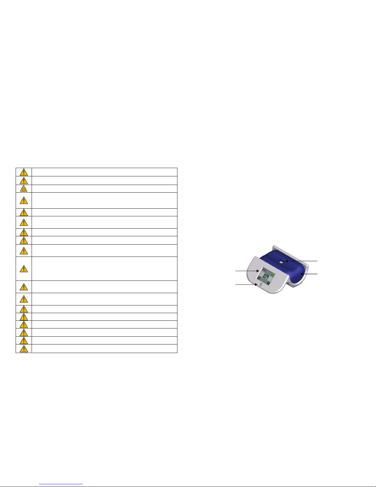
Figure 1. AGE Reader mu front side
4 Description of the AGE Reader mu
The AGE Reader mu is a proprietary device to assist a physician in assessing
cardiovascular risk. This way of non-invasive monitoring uses auto fluorescence
excited by ultraviolet A light in human tissue.
The AGE Reader mu consists of a small enclosure (considered as applied part) and
its detachable silicone mat for the patient to rest his arm on during the
measurement. The AGE Reader mu is operated from a touchscreen with LED
backlight, and controlled by an internal micro controller running dedicated AGE
Reader mu Software. This software allows the user to change his preferences and
calculates the AGE Reader measurement result. Results of the measurements are
presented as an absolute value numerical and can be displayed in a graph on the
screen. The AGE Reader mu is powered by an accompanying medically approved
external power supply connected to the mains. The AGE Reader mu can also be
powered from the internal rechargeable Lithium ion battery.
Contents of packaging:
AGE Reader mu
User manual
External power supply part number CFR51000 or CFR52000
Mains plug set to comply with regulations for use in country of usage
The AGE Reader mu (figure 1) has the following external features:
Enclosure with detachable silicone mat.
3,5” touchscreen from which the device is operated and all necessary
information during use is presented visually to the user.
Measuring window on the upper side of the AGE Reader mu.
Power button to turn the device on and off.
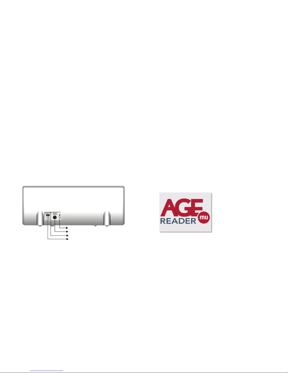
Rear panel at the back of the device (figure 2) with:
o Power inlet for the medically approved power supply.
o USB port for firmware upgrades (protected by a cover).
o Blue LED to indicate when the internal battery is charging.
Power button
Touch
screen
Measurement
window
Detachable
silicone mat
Page 4
AGE Reader mu Installing the AGE Reader mu
User Manual
5
5 Installing the AGE Reader mu
1. Place the AGE Reader mu on a horizontal, flat and stable surface.
2. Attach the correct mains connector plug to the DiagnOptics power supply
accompanying the device and plug it in to the mains outlet.
3. Insert the power plug in the power inlet, which is located on the rear panel
at the backside of the AGE Reader mu (figure 2). A blue LED will light up
when the battery is being charged.
4. The AGE Reader mu can now be turned on by the power button located
on the front of the AGE Reader mu (figure 1). The ‘standby’ symbol on the
button will light up green if the device is in its ‘power on’ state.
5. The dedicated AGE Reader mu Software is preinstalled and will start
automatically.
IMPORTANT: ONLY USE USB CABLE INLET FOR FIRMWARE UPGRADES
Figure 2. AGE Reader mu rear panel
Charging LED
Power inlet
Reset switch
USB inlet
AGE Reader mu Instructions for use
User Manual
6
6 Instructions for use
6.1 Starting the AGE Reader mu
When starting the AGE Reader mu for the first time it is recommended that you
charge the internal battery completely before use. This will extend the battery life.
Insert the power plug into the power inlet that is located on the rear of the AGE
Reader mu, labelled as “Power Inlet” (figure 2). The blue charging LED will light up
when the battery is charging, when the charging LED is off, the battery is fully
charged.
Turn the AGE Reader mu on by pressing the ‘power button’ (figure 1). During the
start-up phase nothing is displayed on the touchscreen and the power button will
not be lit. Part of this initialization is a self-test of the AGE Reader mu’s internal light
sources. Notice that some light will be emitted from the measurement window for a
short period during this phase this is completely harmless.
If the start-up is unsuccessful the power button will be lit red in a blinking fashion.
The blinking pattern corresponds to the error code as described in section 9.2.
Upon a successful start-up the graphical display will show the AGE Reader mu
screen as shown below and the power button will be lit steady green.
Figure 3. Start screen
Shortly after displaying the start screen the AGE Reader mu main screen will
become visible (see section 6.2) indicating that the AGE Reader mu is fully
operational.
6.1.1 Turning the AGE Reader mu off
Turn the AGE Reader mu off by pressing the ‘power button’ (figure 1).
Page 5
AGE Reader mu Instructions for use
User Manual
7
6.2 Main screen
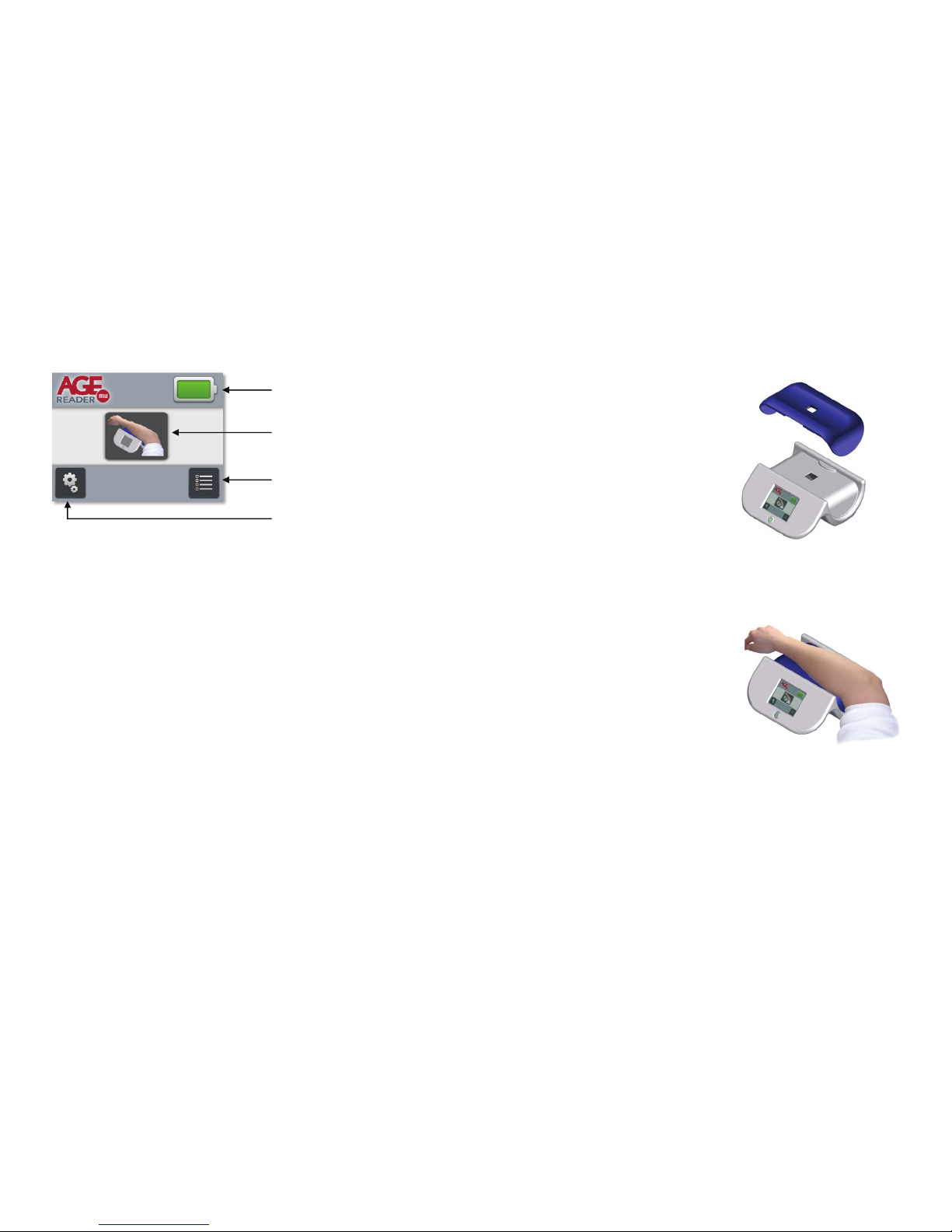
Figure 4. Main screen
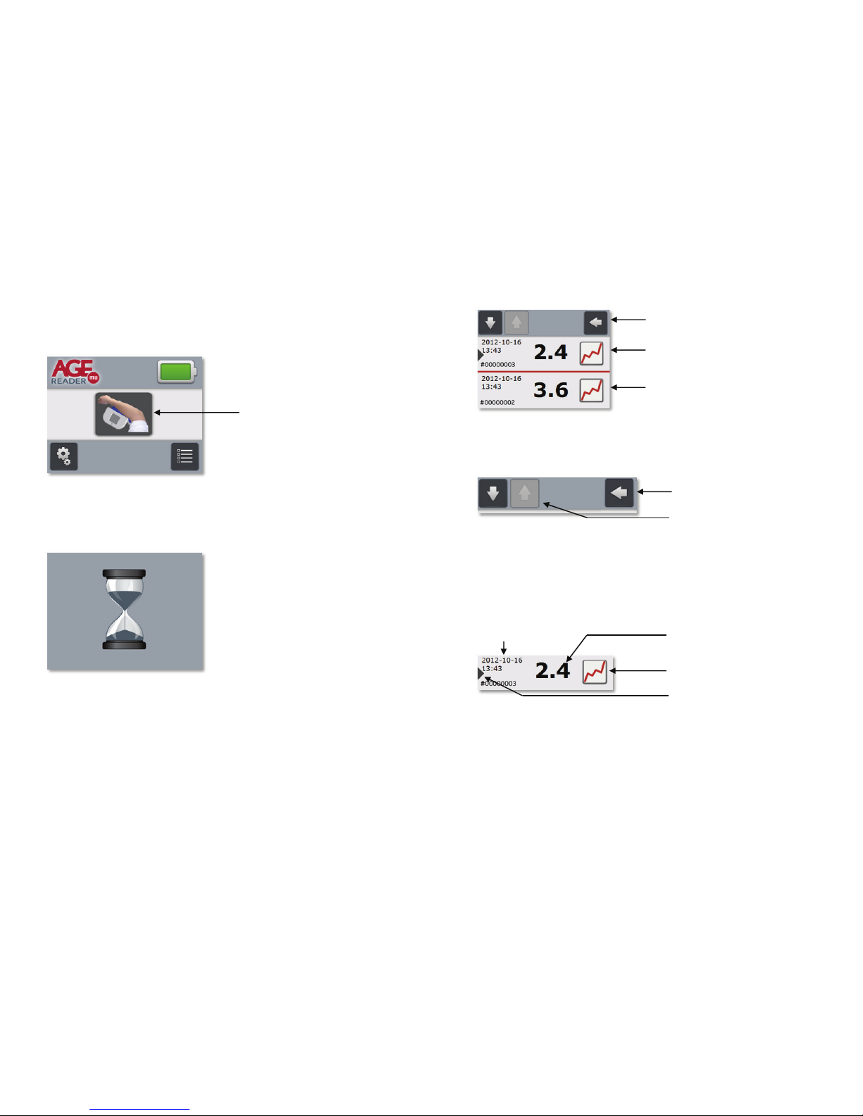
The figure above shows the Main screen which appears when the AGE Reader has
initialized successfully. The top section of the Main screen shows the AGE Reader
mu logo and the Battery charge indicator.
Prominently present at the centre of the screen is the Start measurement button
which, when pressed, starts an AGE Reader measurement (see section 6.3.3).
The last twenty measurement results are stored by the AGE Reader mu. A list of
these measurement is available on the Measurement Results Screen. This screen
is accessible by pressing the Measurement Results button at the bottom-right
corner of the Main screen. If no measurement results are available yet, the
Measurement Results button will be shown in inactive state.
In the bottom-left corner of the Main screen the Settings button is located. By
pressing this button the user can navigate to the Settings screen. For more
information see section 6.4 Settings screen.
Battery charge indicator
Start measurement button
Settings button
Measurement Results button
AGE Reader mu Instructions for use
User Manual
8
6.3 Measurement
6.3.1 Prepare for measurement
Check if the measurement window of the AGE
Reader mu is clean, if not clean the
measurement window first.
See chapter 8 for instructions.
Ensure that the silicon mat is positioned
properly. The silicon mat has a symmetrical
shape to ease positioning on the AGE
Reader mu.
The two notches on both side of the top
surface align the mat with the measurement
window of the AGE Reader mu (figure 5).
Make sure that the mat touches the top
surface of the AGE Reader mu everywhere by
mildly pressing the mat.
Figure 5. Silicon mat positioning
The patient’s dominant forearm should be
placed on the AGE Reader mu as
indicated in figure 6. Ensure that the arm
lies in a relaxed position to avoid arm
movements during the measurement.
Measurements are preferably performed on
the inner side of the dominant lower forearm
on healthy undamaged skin without
birthmarks, excessive hair growth or tattoos
(see chapter 2).
Figure 6. Patient arm position
Page 6
AGE Reader mu Instructions for use
User Manual
9
6.3.3 Performing a measurement
A new measurement is started from the Main screen by pressing the Measurement
button as indicated in the figure below.
Figure 7. Measurement button on Main screen
After pressing the Measurement button the Measurement progress screen will be
shown (figure 8). A measurement takes only a few seconds to complete.
Figure 8. Measurement progress screen
Upon a successful measurement the AGE Reader mu will advance to the
Measurement Results screen (figure 9). This screen will show the last
measurement at the top of the list of measurement results, which is marked with a
red dot to distinguish it from the older measurement results.
Start measurement button
AGE Reader mu Instructions for use
User Manual
10
Last measurement result
Figure 9. Measurement result screen
In order to properly describe the Measurement result screen each part is explained
separately, starting off with the Navigation bar.
Figure 10. Navigation bar
To leave the Measurement results screen and return to the Main screen press the
Return button. In order to navigate through the list of measurement results use the
Browse buttons located at the top-left of the screen. When reaching the top or
bottom of the list the Up button or Down button will be shown in inactive state (see
figure 10) for the Up button. The navigation bar remains visible at the top of the
screen at all times when browsing through the list.
Each measurement result is represented in the list as a row (figure 11).
Figure 11. One single measurement result
The AGE Reader measurement result is displayed at the centre of the row in large
font. The corresponding date and time of measurement are displayed at the top-left
using the date and time formats as configured in section 6.4 Settings screen.
The measurement results are listed in reverse order: the most recent measurement
result is always at the top of the list and the oldest measurement result is at the
bottom of the list. Put simply: browsing down the list is like going back in time. The
Last measurement indication is visible for the most recent measurement result.
Older measurement result
Navigation bar
Return button
Browse buttons
Graph button
Date & Time
AGE Reader
measurement result
Last measurement indication
Page 7
AGE Reader mu Instructions for use
User Manual
11
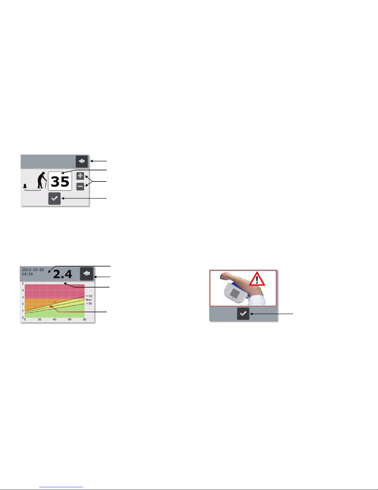
An on-screen measurement report will be generated when pressing the Graph
button which is located at the right of each row. After doing so, it is required to enter
the subject’s age in the Age screen (figure 12).
Figure 12. Age screen
When the Return button is pressed the generation of a measurement report is
aborted and the Measurement results screen is presented again.
By default the Age field this will show the value 35. This value can be altered by
operating the Age input buttons. Pressing the plus-sign will increase the age value
and pressing the minus-sign will reduce the age value.
When the Age field properly reflects the subject’s age press the Confirm button to
generate the actual measurement report.
Figure 13. Measurement report
Press the Return button to leave the Measurement report screen and return to the
Measurement results screen.
Return button
Age field
Age input buttons
Confirm button
Return button
Measurement result in
g
raph
AGE Reader
measurement result
Date & Time
AGE Reader mu Instructions for use
User Manual
12
The date and time (Date & Time) of the measurement and the numerical
representation of the AGE Reader measurement result are displayed at the top of
the screen.
The on-screen measurement report is a graph in which the Measurement result is
drawn as a small black square representing the measured result at the given age.
See chapter 7 for more information about AGE Reader measurement results and an
explanation of the graph.
6.3.4 Problems during measurement
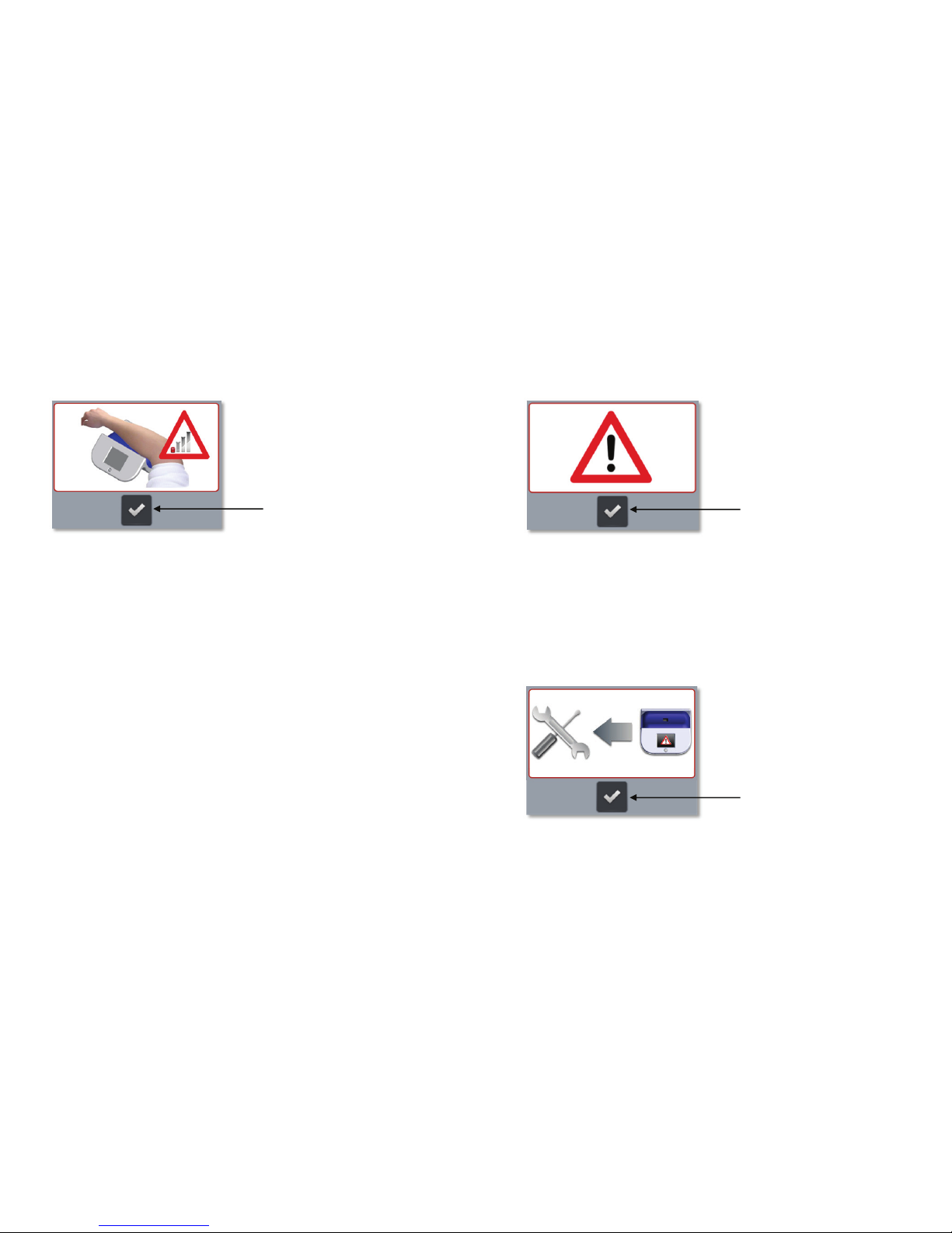
If the AGE Reader mu is not able to successfully perform the measurement it will
abort the measurement and indicate the problem to the user. Three problem
indications exist and will be explained subsequently:
Measurement setup error indication
Low-signal error indication
Internal error indication
Measurement setup error indication
If during measurement the measurement mat is not placed properly on the AGE
Reader mu or if the subject’s arm doesn’t completely cover the measurement
window ambient light can leak into the measurement window and interfere with the
measurement. Although a proper mat and arm position is the responsibility of the
user, the AGE Reader mu is capable of detecting light leakage to some extent.
When the AGE Reader mu detects any light leakage the measurement will be
aborted and the Measurement setup error screen will be displayed as an indication
to the user (figure 14).
Figure 14. Measurement setup error indication
See section 6.3.1 for instructions and check if both mat and arm are positioned
properly before retrying the measurement. Press the Confirm button to return to the
Main screen from where a new measurement can be started.
Confirm button
Page 8
AGE Reader mu Instructions for use
User Manual
13
Low-signal error indication
If the measured fluorescence signal from the arm is too low, the AGE Reader mu is
unable to perform a reliable measurement. It will then abort the measurement and
raise a low-signal error (figure 15).
Figure 15. Low-signal error indication
In general a low-signal error results from a patient’s arm skin that has too much
dark pigment. This in turn might be caused e.g. by birth marks, freckles or tinted
skin.
See section 6.3.1 Prepare for measurement for instructions on how to position the
patient’s arm before retrying the measurement. Press the Confirm button to return
to the Main screen from where a new measurement can be started. If the problem
persists conclude that the patient’s arm has too much pigment, a measurement with
the AGE Reader mu is not possible.
Confirm button
AGE Reader mu Instructions for use
User Manual
14
External error indication
The External error indication is shown (figure 16) when any of the measurement
parameters has an out of bound value that cannot be directly related to the use of
the AGE Reader mu.
Figure 16. External error indication
Press the Confirm button to return to the Main screen from where a new
measurement can be started. If the Internal error indication remains see section 9.2.
Internal error indication
The Internal error indication is shown (figure 17) in case of an internal system
failure that cannot be directly be solved by the user. The device must be returned to
the manufacturer, see section 12.1 for contact details.
Figure 17. Internal error indication
Press the Confirm button to return to the Main screen.
Confirm button
Confirm button
Page 9
AGE Reader mu Instructions for use
User Manual
15
6.4 Settings screen
6.4.1 Accessing the settings screen
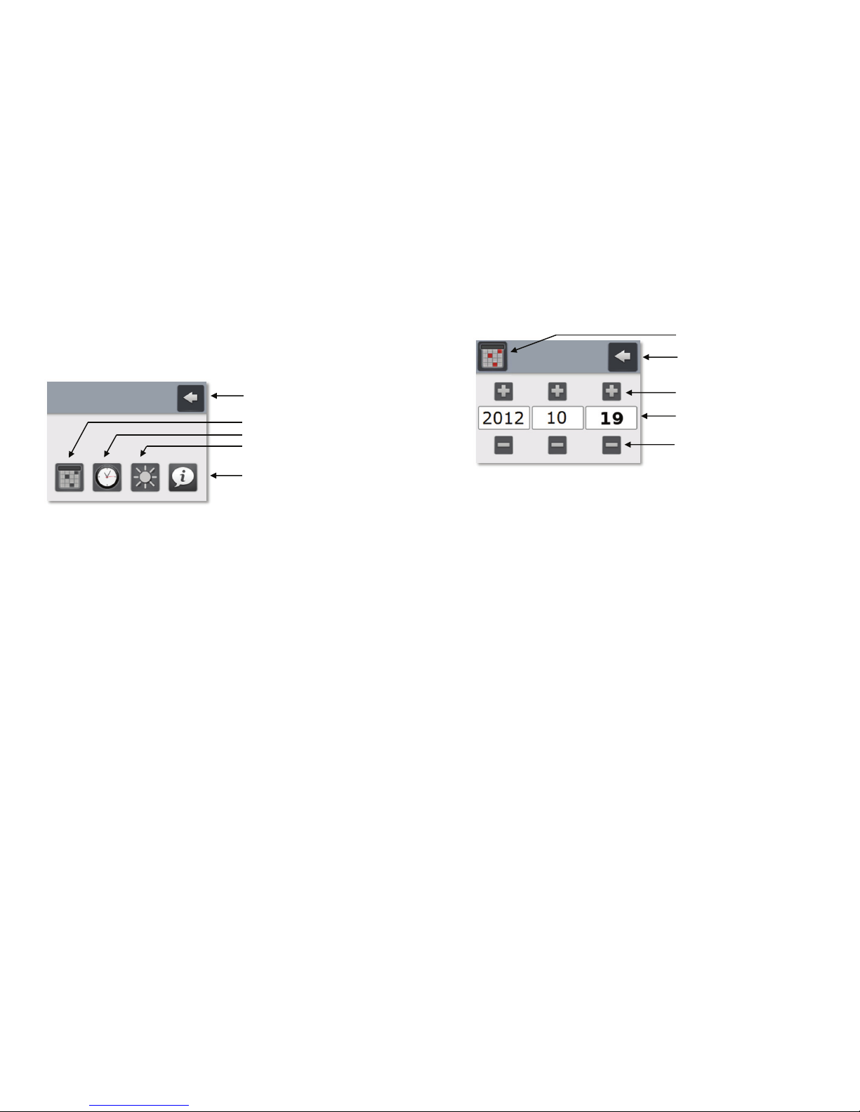
The Settings screen (figure 18) is accessible from the Main screen by pressing the
Settings button on the bottom-left of the Main screen.
Figure 18. Settings screen
Press the Return button to return to the Main screen. Four settings buttons are
available at the bottom of the Settings screen and give access to the following
screens and functionality:
Date screen: Change date and date format
Time screen: Change time and time format
Brightness screen: Change the LCD display brightness
Information screen: Show information about the AGE Reader mu
Return button
Date settings button
Time settings button
Brightness setting button
Information button
AGE Reader mu Instructions for use
User Manual
16
Date screen
Figure 19. Date screen
The user can return to the Settings screen by pressing the Return button at the topright of the screen. The date format can be configured as:
YYYY-MM-DD (figure 19)
DD-MM-YYYY
MM-DD-YYYY
This can be done by pressing the Date format button repeatedly until the requested
date format is shown in the Date fields. In these Date fields the individual year,
month and day values can be recognized as follows:
The year (YYYY) is shown as a four digit number
The day (DD) is shown in bold text.
The month (MM) is shown is shown a normal (non-bold) text.
The date itself can be changed by pressing the Increment button and Decrement
button of the appropriate Date field. Any changes are immediately active.
Return button
Decrement buttons
Increment buttons
Date fields
Date format button
Page 10
AGE Reader mu Instructions for use
User Manual
17
Time screen
Figure 20. Time screen
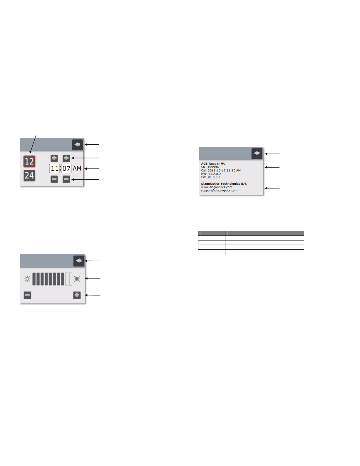
The user can return to the Settings screen by pressing the Back button at the topright of the screen. Choose between 12-hour (figure 20) or 24-hour time format by
pressing the corresponding Time format button.
With the Increment button and Decrement button the actual time can be set. Any
changes are immediately active.
Brightness screen
The brightness of the LCD display can be set in the Brightness screen (figure 21).
Using a lower LCD display brightness setting will reduce the power-consumption of
the AGE Reader mu and prolongs the operating time of the battery.
Figure 21. Brightness screen
The user can return to the Settings screen by pressing the Back button at the topright of the screen. By using the Decrement/Increment buttons the brightness can
be changed instantly.
Brightness indicator
Return button
Decrement/Increment buttons
Return button
Decrement buttons
Increment buttons
Time fields
Time format buttons
AGE Reader mu Instructions for use
User Manual
18
Information screen
The user can select a preferred date format in the Date format screen The Date
format screen is shown below.
Figure 22. Information screen
Press the return button at the top-right of the screen to return to the Settings
screen. The upper part of the Information screen displays information which is
specific for the AGE Reader mu.
The fields concerned are:
Abbreviation Description
SN AGE Reader mu serial number
Cal Date and time of last calibration
HW AGE Reader mu hardware version number
FW AGE Reader mu firmware version number
The Manufacturer information displays the DiagnOptics Technologies B.V. company
homepage URL and the email address of the DiagnOptics Technologies B.V.
support.
Return button
Manufacturer information
AGE Reader mu information
Page 11
AGE Reader mu Background on
User Manual AGE values
19
7 Background on AGE values
Age is the most important factor determining the level of Advanced Glycation Endproducts (AGEs) in tissue. The AGE value as measured by the AGE Reader is also
correlated with age. The reference values for AGE values have been based on 456
measurements in Caucasian subjects without cardiovascular disease (smokers and
non-smokers) [Lutgers et al., Diabetes Care 2006, and Koetsier et al, Diabetes
Technology & Therapeutics, 2010; 12(5):399-403]. Table 2 shows the mean values
of the AGE value for several age decades. AGE values are given in arbitrary units ±
1 standard deviation. N represents the number of subjects in the respective age
groups.
Table 2. Mean Skin auto fluorescence per age decades
Age group
(years)
AGE Reader
measurement
result
N
0-10 0.97 ± 0.17 45
10-20 1.11 ± 0.20 50
20-30 1.53 ± 0.30 62
30-40 1.73 ± 0.42 86
40-50 1.81 ± 0.36 72
50-60 2.09 ± 0.36 64
60-70 2.46 ± 0.57 45
70-80 2.73 ± 0.55 27
80+ 2.71 ± 0.44 5
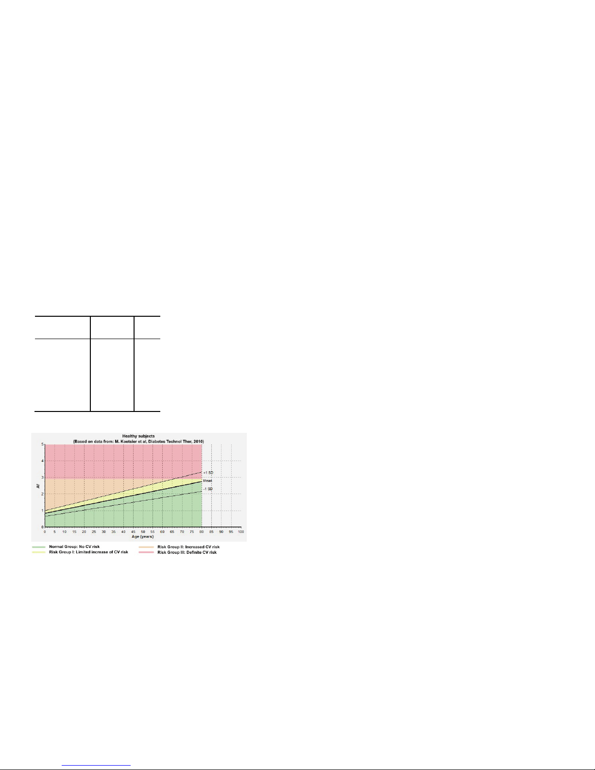
Graph 1. Mean Skin auto fluorescence as function of age
AGE Reader mu Background on
User Manual AGE values
20
Graph 1 shows the mean AGE values as a function of age, together with the lines
representing mean +/- 1 standard deviation. The coloured areas indicate the risk
classes corresponding to the AGE value combined with age value.
No reliable AGE values can be given with the current AGE Reader mu software if
the measured UV reflectance is below 10%. In that case no AGE value is given and
the screen shows a message that a reliable measurement is not possible.
Cardiovascular risk interpretation for type 2 diabetes patients based
on the AGE Reader measurement.
The AGE Reader measurement result increases considerably with age, both in
healthy persons and in those with diabetes or renal disease. Calendar age is in fact
the strongest determinant of the AGE Reader measurement. Keep in mind that
calendar age itself is also by far the strongest risk indicator in terms of
cardiovascular risk (CV risk), as is evident from all known risk scores. Thus, a
healthy elderly person may have a higher measurement result than a much younger
patient with diabetes. Therefore, age-dependent AGE Reader measurements within
levels up to 1 standard deviation (1SD) above the age-corrected mean may serve
as reference values for a certain age, but can be considered normal only for the
corresponding age group.
AGE Reader measurements should be considered as complementary to, and not a
replacement for assessment of conventional cardiovascular risk factors and risk
scores. When other risk factors such as blood pressure or cholesterol levels are
clearly increased, a low AGE Reader measurement is not a reason to withhold
treatment. This especially holds for younger people with extreme values of
conventional risk factors.
Always keep in mind that in case of markedly abnormal AGE Reader
measurements (high or low) one should make sure that the measurement has been
properly performed and that the measured person has not used skin creams, sun
blockers or tanning agents.
Normal Group: No increased CV risk
If the AGE Reader measurement is below or equal to the age-related mean, the
subject has no calendar age-corrected increase in cardiovascular risk. However if
the subject is an elderly person and the result is above 2.5 (even though it is at the
age-related mean), the subject may still have increased cardiovascular risk due to
his/her calendar age.
Risk Group I: Limited increase of CV risk
If the AGE Reader measurement is above the average but within 1SD of the agerelated mean, the subject has a limited increase, corrected for calendar age, in
cardiovascular risk.
Page 12

AGE Reader mu Background on
User Manual AGE values
21
Risk Group II: Increased CV risk
If the measurement result is above 1SD of the age related mean, the subject has an
increased cardiovascular risk. In such case, the advice is to check the levels of
other cardiovascular risk factors such as blood pressure and lipid levels. Depending
on overall CV risk, lifestyle or even pharmaceutical treatment should be considered.
Risk Group III: Definite CV risk
If the AGE Reader measurement result is 2.9 or above, the subject has a definitely
high cardiovascular risk. It is recommended that other cardiovascular risk factors
should be assessed and treated, with low threshold and target values for starting or
intensifying treatment.
Used in combination with conventional risk scores (UKPDS, SCORE) the
following advice applies:
Normal Group: no risk reclassification to be considered
Risk Group I: no risk reclassification to be considered
Risk Group II: consider reclassification to a higher cardiovascular risk class
Risk Group III: classification as high or very high cardiovascular risk class
suggested
AGE Reader mu Cleaning &
User Manual maintenance
22
8 Cleaning & maintenance
8.1 Cleaning instructions
Measurement window.
The measurement window should always be kept clean!
In the design of the AGE Reader mu, special attention was given to allow
cleaning the window by using a removable mat. Place the housing on a
horizontal stable surface and carefully remove the mat in order to clean the
measurement window. Clean the window with a slightly moistened soft nonfluorescent cleaning wipe (for example the soft reusable cleaning wipes used
for spectacles) using a standard 70% alcohol solution. Avoid scratching the
window and take care that no textile or paper fibres remain on the window,
textiles and paper show fluorescence and may affect the measurement! After
cleaning the window, replace the silicone mat in the proper position.
Silicone mat.
The silicone mat can be cleaned with standard mild cleaning agents by
removing the silicone mat. If desired, the mat can be disinfected with alcohol or
chlorohexidine.
Housing & touchscreen.
The housing and touchscreen can be cleaned with standard mild cleaning
agents, for example a slightly moistened cloth. Make sure no fluids enter the
housing at the connector inlets and no fluid collects at the bottom of the
touchscreen.
8.2 Maintenance instructions
This system does not contain parts that can be serviced by the user!
The internal battery can only be serviced by DiagnOptics personnel with use of an
tool.
The AGE Reader mu is a medical instrument that has been carefully calibrated
before use. Small differences exist in the characteristics of the internal optics and
the LED spectrum. Albeit small these differences may affect the measurement
results of the AGE Reader mu and may impede comparisons of results between
individual instruments. Unique calibration files of each individual system are used in
the AGE Reader mu Software.
Never make changes in the system on your own!
If damage occurs only to the silicone mat, the power supply or the mains connector
set, a replacement can be ordered, see chapter 12.
Page 13

AGE Reader mu Problems &
User Manual solutions
23
9 Problems & solutions
9.1 Power supply problems
The AGE Reader mu is either powered by its internal battery or by the supplied
external 9-12VDC power supply (part. nr. CFR51000 or CFR52000). When the
battery voltage drops below a workable level the AGE Reader mu will automatically
be powered down. In this case apply the supplied external 9-12VDC power supply,
after which the AGE Reader mu will immediately be functional again.
If the AGE Reader mu cannot be turned on while the external 9-12VDC power
supply is applied, it is recommended to contact your local distributor or DiagnOptics
Technologies B.V. support.
9.2 Problems during operation
When the AGE Reader mu is turned on, the software will initialize the system. If a
fault condition occurs in this start-up phase a fault code is presented by red blinking
of the power button with a pattern, see below. If the system successfully passes the
start-up phase it enters the operational phase which is reflected by lighting the
power-button green continuously.
If a fault condition occurs during the operational phase the AGE Reader mu can no
longer guarantee a reliable measurement. Upon a fault the AGE Reader mu will
shut-down and the power button will blink red with a pattern that reflects the fault
code.
Fault codes can be recognized by the blinking pattern of the power-button. The
blinking pattern is repeated continuously with a few seconds pause. The pattern
itself consists of long and short blink periods (Represented as L and S respectively
in the blink pattern example below). It is recommended to write down the blink
pattern and contact your local distributor or DiagnOptics Technologies B.V. support.
Please keep the AGE Reader mu serial number in range if you contact
DiagnOptics.
Example error pattern:
Blink pattern: ____ __ __ __ __ ____
L S S S S L
At any time, the user can press the power-button to shut down the AGE Reader mu.
AGE Reader mu Technical specifications
User Manual
24
10 Technical specifications
Operation: Continuous operation
Power: 9-12 VDC from external power supply
7,2 VDC from rechargeable Li-Ion battery CFR50200
Output UV-A light λ
p
= 375nm E = 7,81E-01 W/m2 @ 0,2m
Blue light λ
p
= 460nm E = 1,83E-01 W/m2 @ 0,2m
Infrared light λ
p
= 880nm E = 6,26E-02 W/m2 @ 0,2m
Dimensions: Width x depth x Height : 210 x 193 x 81 mm
Weight: 0,75 kg
Material (ext.): Enclosure: ASA (V-0 quality)
Mat: Silicone
Operating Conditions:
o Temperature range: Lower limit + 10ºC - Upper limit + 30°C
o Relative humidity: 30% to 75% non-condensing
Storage & Transport Conditions:
o Temperature range: Lower limit - 40ºC - Upper limit + 70°C
o Relative humidity: 10% to 100% non-condensing
Power Supply (CFR51000):
Input: 100 - 240 VAC 0,3A 50 – 60 Hz
Output: 9 VDC 1,1 A
Power Supply (CFR52000):
Input: 100 - 240 VAC 0,4 - 0,2A 50 – 60 Hz
Output: 12 VDC 1,1 A
Classifications:
Classification to 93/42/EEC Class IIa
Classification to IEC 60601-1 Class II
Protection against electric shock Type B
Directive(s): Council Directive 93/42/EEC
Standard(s): Safety: IEC 60601-1 3
rd
edition
EMC: IEC 60601-1-2 3
rd
edition
Risk Analysis: ISO 14971 : 2009
Power Supply (CFR51000 & CFR52000):
Classification to IEC 60601-1 Class I
Standard(s): Safety: UL/EN/ IEC 60601-1 3
rd
edition
Battery:
Standard(s): - UL 1642 Certificate MH12210
- UL 1642 Certificate MH12566
- UL 1642 Certificate MH19896
Disposal:
Regulations vary for different countries. Dispose in accordance with local
regulations.
Page 14
AGE Reader mu Marking on the
User Manual AGE Reader mu
25
11 Marking on the AGE Reader mu
Each device shall be accompanied by all information needed to safely install and
use the AGE Reader mu and to identify DiagnOptics as its manufacturer.
This information consists of:
1. Information on the labels, on the device.
2. Information and instructions, on packaging.
3. Information and instructions, in this user manual.
As far as practical and appropriate, the information needed to install the device
safely is set out on the labelling on the device itself and/or on the packaging for
each unit. Where possible, this information is presented in the form of symbols in
conformance with the harmonized standards.
The labelling on the device itself consists of:
1. Rear label: Identification of connector inlets, reset switch and charge
LED
2. Serial label: Serial number and contact information of the manufacturer
All necessary information for product identification, product
specification, installation, use and warnings.
3. Button label: Power button with symbol and information of power state.
4. Packaging label: Information of content and manufacturer
11.1 The rear label
The rear label is located at the back of the housing of the AGE Reader mu. This
label shows all necessary information for installation, use and applicable warnings.
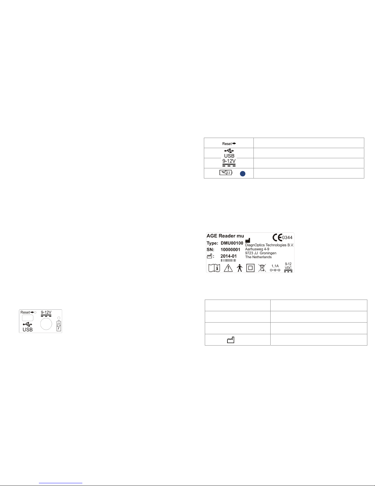
The rear label contains two connector inlets (figure 23), one inlet for the
accompanying power supply, one connector inlet for the USB connection and will
identifies them as such. A blue LED will light up when the battery is charging. A
reset switch is present to reset the device if necessary.
Figure 23. Rear label.
AGE Reader mu Marking on the
User Manual AGE Reader mu
26
Table 3. Used symbols on rear label
Identifies reset-switch
Identifies USB inlet
Identifies power supply inlet
Identifies battery charging indicator,
blue light means charging
11.2 The serial label
The serial label (figure 24) is located on the back of the front panel of the AGE
Reader mu. This label shows the serial number and contact information of the
manufacturer as well as all necessary information for product identification, product
specification, installation, use and warnings.
Figure 24. Serial label
Table 4. Used symbols on serial label
AGE Reader mu Identification of device, device name
Type: CFR00100 Type identification
SN: 100001 Serial number (NEN-EN 980).
2014-01
Date of manufacture; YYYY-MM (NEN-EN 980).
Page 15
AGE Reader mu Marking on the
User Manual AGE Reader mu
27
11.3 Power button
The Power button is located at the front of the
AGE Reader mu and shows the symbol
“Stand-by condition” (figure 25).
The condition “ready for use” is indicated
by visual means; the symbol will light up green.
The conditions “device error”
will be indicated by visual means, the symbol
will light up by an red flashing indicator light.
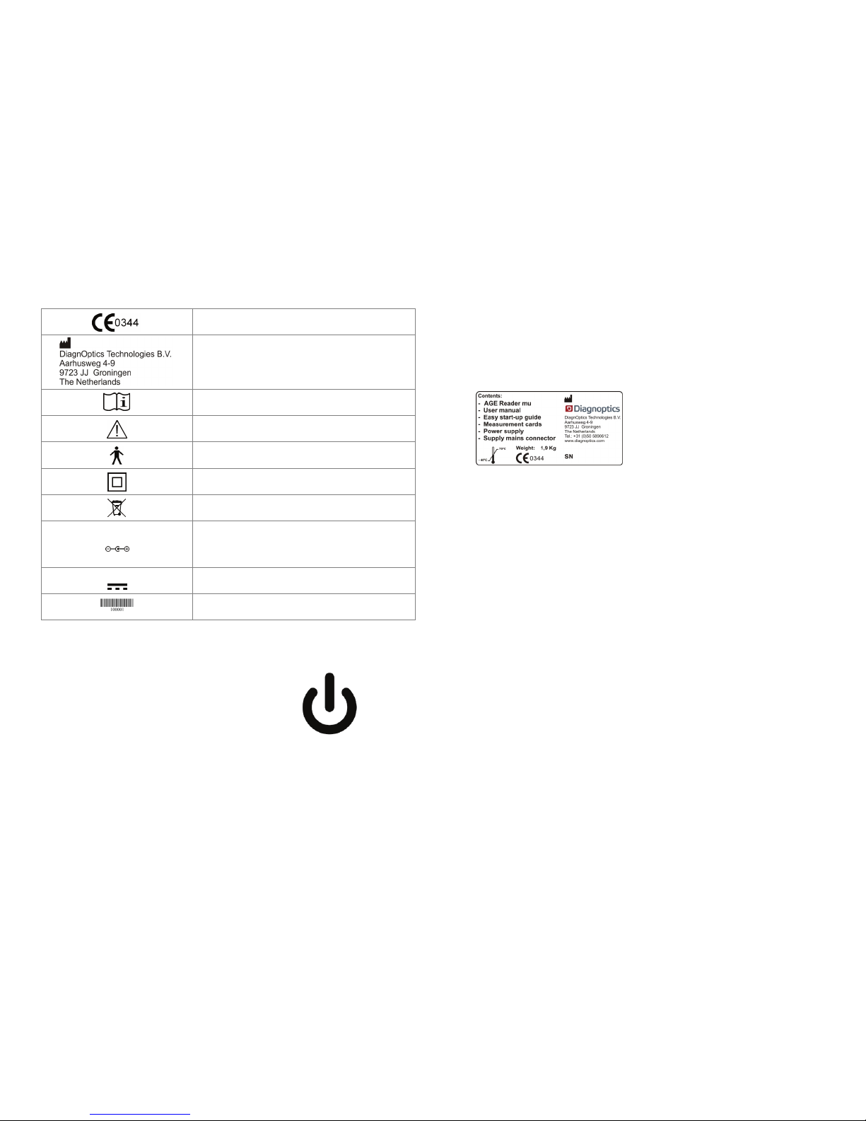
CE-Mark & Notified body number (6 mm high)
Identifies DiagnOptics Technologies B.V. as its
manufacturer with name and contact information.
( NEN-EN 980)
Read Instructions for use (ISO 7000-1641)
Caution, read instruction for use for specific warnings (ISO
7
000-0434A)
Type B applied part (IEC 60417-5840)
Class II equipment ( IEC60417-5172)
Indicating separate collection for electronic equipment
(2002-96-EC)
Polarity symbol, indicates that the centre (tip) of the power
plug is Positive (+) and the barrel of the power plug is
Negative (-).
Direct current symbol (IEC60417-5031)
Barcode for production purposes.
Figure 25. Stand-by symbol
AGE Reader mu Marking on the
User Manual AGE Reader mu
28
11.4 Packaging label
Each AGE Reader mu together with a user manual and power supply will be
packed in protective packaging right after production. This packaging should be
used for storage and shipment.
All packaging materials can be recycled if disposed of separately.
All following information is put on each package by the label as in figure 26:
DiagnOptics logo & address
Serial number
Content
Weight
Environmental conditions for transport
Figure 26. Packaging label
Page 16
AGE Reader mu Spare parts &
User Manual accessories
29
12 Spare parts & accessories
12.1 Spare Parts
If damage occurs to the silicone mat, the power supply or the mains connector set,
a replacement can be purchased via DiagnOptics or its representatives.
Be sure that the damage is limited only to the silicone mat or the power supply.
If any doubt exists that damage has been done to the AGE Reader mu itself, please
contact DiagnOptics or its representatives. Do not use the device if there is visible
damage and/or sharp edges.
Send your request by e-mail or fax and clearly state the serial number of the
concerning AGE Reader mu. Also include the article number(s) of the spare parts
you would like to order. The article numbers for the spare parts of this device are
listed in table 5:
Table 5. Spare parts
The contact details for technical support are:
Spare part Article number
Silicone mat CFR01200
External power supply 9VDC CFR51000
Mains connector set (9VDC) CFR51100
External power supply 12VDC CFR52000
Transport Case DMU05100
AGE Reader mu Liability &
User Manual warranty
30
13 Liability & warranty
13.1 Liability
DiagnOptics Technologies and its respective directors, officers, employees and
agents and their respective successors, heirs and assigns, are not liable for any
damages, losses, obligations, costs and expenses, including attorney’s fees that
may incur by third parties in connection with a claim for damage to or loss of
tangible personal property, breach of warranty, or for bodily injury, sickness and/or
death sustained by any customer (collectively “Damage”) if or where the Damage is
caused by or arises in connection with (a) improper use of the AGE Reader mu, (b)
unauthorized modification of the AGE Reader mu, (c) fault or negligence by the
user, (d) breach of any warranty or other obligation by the user or (e) invalid or
wrong conclusions, and any consequences thereof, drawn by third parties from the
measurement results provided by the AGE Reader mu.
13.2 Warranty
The warranty supplied with this AGE Reader mu System is provided separately.
13.3 Declaration of Conformity
The Declaration of Conformity is provided separately.
Page 17
AGE Reader mu Electromagnetic
User Manual compatibility
31
14 Electromagnetic compatibility
The AGE Reader mu needs special precautions regarding EMC and needs to be
installed and put into service according to the EMC information provided
in this user manual.
14.1 Essential performance
The use of the medical device does not depend on essential performance.
14.2. Electromagnetic emissions
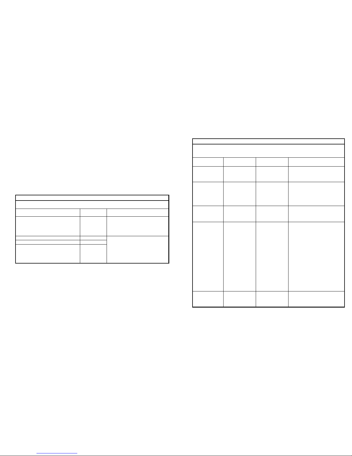
Guidance and manufacturer’s declaration – electromagnetic emissions
The AGE Reader mu is intended for use in the electromagnetic environment specified below.
The customer or the user of the AGE Reader should assure that it is used in such an environment.
Emissions test Compliance
Electromagnetic environment –
guidance
RF emissions
CISPR 11
Group 1
The AGE Reader mu uses RF energy
only for its internal function. Therefore,
its RF emissions are very low and are
not likely to cause any interference in
nearby electronic equipment.
RF emissions CISPR 11 Class B The AGE Reader mu is suitable for
use in all establishments, including
domestic establishments and those
directly connected to the public low
voltage power supply network that
supplies buildings used for domestic
purposes.
Harmonic emissions IEC 61000-3-2 Class A
Voltage fluctuations / flicker emissions
IEC 61000-3-3
Complies
AGE Reader mu Electromagnetic
User Manual compatibility
32
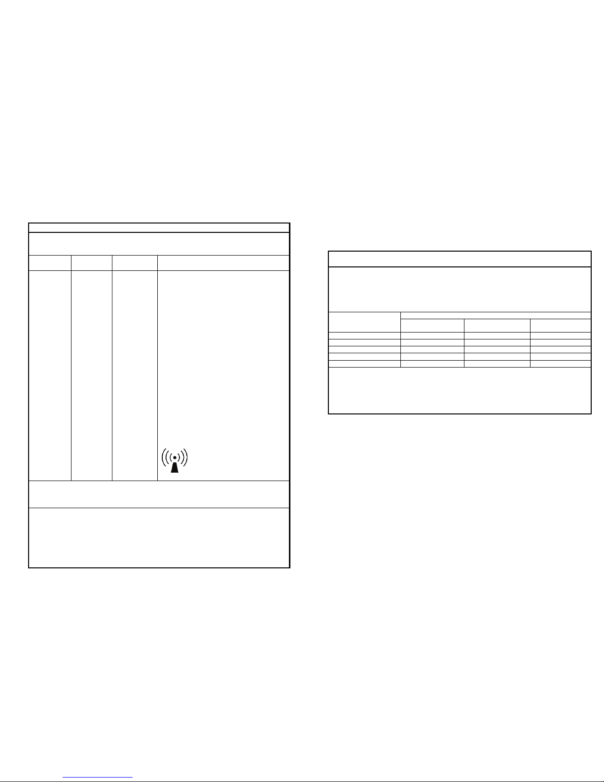
14.3. Electromagnetic immunity
Guidance and manufacturer’s declaration – electromagnetic immunity
The AGE Reader mu is intended for use in the electromagnetic environment specified
below. The customer or the user of the AGE Reader mu should assure that it is used in
such an environment.
Immunity test IEC 60601 test
level
Compliance
level
Electromagnetic environment
– guidance
Electrostatic
discharge (ESD)
IEC 61000-4-2
6 kV contact
8 kV air
6 kV contact
8 kV air
Floors should be wood, concrete or
ceramic tile. If floors are covered
with synthetic material, the relative
humidity should be at least 30 %.
Electrical fast
transient/burst
IEC 61000-4-4
2 kV
for power
supply lines
1 kV
for input /
output lines
2 kV
for power
supply lines
1 kV
for input /
output lines
Mains power quality should be that
of a typical commercial or hospital
environment.
Surge
IEC 61000-4-5
1 kV
line(s) to line(s)
2 kV
line(s) to earth
1 kV
line(s) to line(s)
2 kV
line(s) to earth
Mains power quality should be that
of a typical commercial or hospital
environment.
Voltage dips, short
interruptions and
voltage variations
on power supply
input lines
IEC 61000-4-11
<5 % UT
(>95 % dip in UT)
for 0,5 cycle
40 % UT
(60 % dip in UT)
for 5 cycles
70 % UT
(30 % dip in UT)
for 25 cycles
<5 % UT
(>95 % dip in UT)
for 5 s
UT is the a.c. mains
voltage prior to
application of the
test level.
<5 % U
T
(>95 % dip in UT)
for 0,5 cycle
40 % UT
(60 % dip in UT)
for 5 cycles
70 % UT
(30 % dip in UT)
for 25 cycles
<5 % UT
(>95 % dip in UT)
for 5 s
Mains power quality should be that
of a typical commercial or hospital
environment. If the user of the AGE
Reader requires continued
operation during power mains
interruptions, it is recommended
that the AGE Reader be powered
from an uninterruptible power
supply or a battery.
Power frequency
(50/60 Hz)
magnetic field
IEC 61000-4-8
3 A/m 3 A/m Power frequency magnetic fields
should be at levels characteristic of
a typical location in a typical
commercial or hospital environment.
Page 18
AGE Reader mu Electromagnetic
User Manual compatibility
33
Guidance and manufacturer’s declaration – electromagnetic immunity
The AGE Reader is intended for use in the electromagnetic environment specified below.
The customer or the user of the AGE Reader mu should assure that it is used in such an
environment.
Immunity
test
IEC 60601
test level
Compliance
level
Electromagnetic environment –guidance
Conducted RF
IEC 61000-4-6
Radiated RF
IEC 61000-4-3
3 Vrms
150 kHz to 80
MHz
3 Vrms
80 MHz to 2,5
GHz
3 Vrms
3V/m
Portable and mobile RF communications
equipment should be used no closer to any part of
the AGE Reader, including cables, than the
recommended separation distance calculated
from the equation applicable to the frequency of
the transmitter.
Recommended separation distance:
, √
, √ for 80 MHz to 800 MHz
, √ for 800 MHz to 2,5 GHz
where P is the maximum output power rating of
the transmitter in watts (W) according to the
transmitter manufacturer and d is the
recommended separation distance in metres (m).
Field strengths from fixed RF transmitters, as
determined by an electromagnetic site survey,
a
should be less than the compliance level in each
frequency range.
b
Interference may occur in the vicinity of equipment
marked with the following symbol:
NOTE 1 At 80 MHz and 800 MHz, the higher frequency range applies.
NOTE 2 These guidelines may not apply in all situations. Electromagnetic propagation is affected by
absorption and reflection
from structures, objects and people.
a) Field strengths from fixed transmitters, such as base stations for radio (cellular/cordless)
telephones and land mobile radios, amateur radio, AM and FM radio broadcast and TV
broadcast cannot be predicted theoretically with accuracy. To assess the electromagnetic
environment due to fixed RF transmitters, an electromagnetic site survey should be considered.
If the measured field strength in the location in which the AGE Reader is used exceeds the
applicable RF compliance level above, the AGE Reader should be observed to verify normal
operation. If abnormal performance is observed, additional measures may be necessary, such
as re-orienting or relocating the AGE Reader.
b) Over the frequency range 150 kHz to 80 MHz, field strengths should be less than [V
1
] V/m.
AGE Reader mu Electromagnetic
User Manual compatibility
34
14.4. Distances between RF equipment
Recommended separation distances between portable
and mobile RF communications equipment and the AGE Reader mu
The AGE Reader mu is intended for use in an electromagnetic environment in which
radiated RF disturbances are controlled. The customer or the user of the AGE Reader
mu can help prevent electromagnetic interference by maintaining a minimum distance
between portable and mobile RF communications equipment (transmitters) and the AGE
Reader mu as recommended below, according to the maximum output power of the
communications equipment.
Rated maximum output
power of transmitter
W
Separation distance according to frequency of transmitter m
1,2√ 1,2√ 2,3√
0,01 0,12 0,12 0,23
0,1 0,38 0,38 0,73
1 1,2 1,2 2,3
10 3,8 3,8 7,3
100 12 12 23
For transmitters rated at a maximum output power not listed above, the recommended separation
distance d in metres (m) can be estimated using the equation applicable to the frequency of the
transmitter, where P is the maximum output power rating of the transmitter in watts (W) according to
the transmitter manufacturer.
NOTE 1 At 80 MHz and 800 MHz, the separation distance for the higher frequency range applies.
NOTE 2 These guidelines may not apply in all situations. Electromagnetic propagation is affected
by absorption and reflection from structures, objects and people.
Page 19

DiagnOptics Technologies B.V.
Aarhusweg 4-9
9723 JJ Groningen
The Netherlands
Tel.: +31(0)50 589 0612
Email: [email protected]
http: www.diagnoptics.com
 Loading...