

Page 1

Page 2

2
Table of Contents
3 Read Me
3 Safety Warning & Caution
4 Safety Guidelines
5 FCC Compliance
7 Quick Start
7 In-Cab Display
8 Accessories
9 Cable Installation
9 Windshield Mount Installation
10 Touch Screen
11 Main Menu
12 Update Software
12 Downloading Ignition
13 Product Updates
14 Tuning
14 Tune Vehicle
16 Restore Vehicle
17 Custom Tuning (EX Platinum)
20 Performance Tests
20 0-60, 0-100, 1/4 Mile, & 1/8 Mile Tests
22 Settings
22 Display & Audio Settings
23 WiFi Setup
24 Check for Updates
25 Unit of Measure
26 Restore Default Settings
26 Restore Default PIDs
27 Alert Settings
28 Gauges & Logging
28 Gauge Layouts
30 Theme Settings
31 Wallpaper
32 Individual Gauge Setup
34 Recording
34 DataViewer Download
35 DataViewer
36 Diagnostics
36 Trouble Codes
37 Help/Info
37 Device Info
38 Tutorials
38 F.A.Q’s
39 Tech Support
EX Devices Only
Page 3
3
Safety Warning & Caution
Read Me
Throughout this User Manual you will see important messages
regarding your safety or the protection of your vehicle. These messages
are designated by the words WARNING, CAUTION, or NOTICE.
A WARNING indicates a hazardous situation which, if not avoided, will
result in death or serious injury.
A CAUTION indicates a hazardous situation which, if not avoided, could
result in minor or moderate injury.
NOTICE
A NOTICE indicates a condition that could cause damage to the product
or your vecicle.
The product you have purchased is a high-performance product. As
such, it does present some risks of which you should be fully aware. Do
not use this product until you have carefully read the following safety
information and the Owner Agreement.
NOTE: After the display has been installed, the following warning
message will appear when powered on. Swipe the screen upward
to read the full disclamer.
If you agree with the disclamer, select Yes to continue.
WARNING: Prior to use, read the User Manual. Misuse of the
device could result in trac accidents, death or serious injury, and/or
damage to your vehicle. POWERTEQ IS NOT RESPONSIBLE FOR AND
SHALL HAVE NO LIABILITY TO YOU FOR ANY CLAIMS ARISING OUT OR OR
RELATING TO ANY MISAPPLICATION OF THE TRINITY 2, CUSTOM TUNES,
IMPROPER USE OF CALIBRATIONS, MALFUNCTION OR LACK OF LEGAL
COMPLIANCE FOR CUSTOM PROGRAMS CREATED BY THIRD PARTIES.
DO YOU AGREE?
WARNING
CAUTION
Page 4

4
Safety Guidelines
Before using device, read and understand the user manual, including
these additional safety instructions. Failure to do so could result in
DEATH or SERIOUS INJURY.
• Do not exceed legal speed limits on public roadways. Violating trac laws is
dangerous and could result in injury or vehicle damage or both.
• Use any enhanced speed capabilities of this product only in closed circuit, legally
sanctioned racing environments expressly for this purpose. Violating trac laws is
dangerous and could result in injury or vehicle damage or both.
• Do not operate the device while driving. Distracted driving could result in trac
accidents, death or serious injury, and/or damage to your vehicle.
• Always perform all adjustments or changes while stopped. Changing a setting while
driving can interfere with your attention to roadway conditions and could result in
injury or vehicle damage or both.
• Do not stack products. “Stacking” performance-enhancing devices or other
improper installation can cause power train failure on the road. Other products may
have features incompatible with your device. Follow all installation and operating
instructions.
• Some modications may aect other parts of your vehicle. For example, if you
remove/adjust the speed limiter in your vehicle, be sure your tires and other
components are rated for the increased speeds they will have to withstand. Not
doing so can lead to loss of vehicle control. Modify the speed limiter only for use
in closed circuit, legally sanctioned racing environments, not for use on public
roadways.
WARNING
NOTE: The stickers included in some products apply to products that have
recieved CARB exemption for emissions compliance.
This product may meet the emissions compliance requirements of the California
Air Resources Board and Federal Environment Protection Agency. If so, it is
legal for sale and use on pollution-controlled vehicles operated on public streets
and highways. The device must be installed and operated according to the
instruction provided in this user manual. Inluded with these compliant products is
a sticker for you to keep in your vehicle. You can either adhere it somewhere on
the vehicle (e.g., the inside end of driver’s door) or simply store it in your glove
box. The purpose of these stickers is to inform anyone who may have questions
regarding the use of this product and how it aects emissions. For example, it
would be something to show an emissions technician if questioned when taking
your vehicle in for an emissions check to let him/her know the product is CARB
emissions compliant.
Page 5

5
Contains FCC ID: TF8-1003
Contains IC: 5969A-1003
DiabloSport Trinity2 Programmer
This device complies with Part 15 of the FCC Rules. Operation is subject
to the following two conditions: (1) This device may not cause harmful
interference, and (2) this device must accept any interference received,
including interference that may cause undesired operation.
Warning: Changes or modications to this device not expressly approved
by DiabloSport, LLC could void the user’s authority to operate the
equipment
Note: This equipment has been tested and found to comply with the
limits for a Class B digital device, pursuant to Part 15 of FCC Rules.
These limits are designed to provide reasonable protection against
harmful interference in a residential installation.This equipment
generates, uses, and can radiate radio frequency energy and, if not
installed and used in accordance with the instructions, may cause
harmful interference to radio communications. However, there is no
guarantee that interference will not occur in a particular installation.
If this equipment does cause harmful interference to radio or television
reception, which can be determined by turning the equipment o and on,
the user is encouraged to try to correct the interference by one or more
of the following measures:
• Reorient or relocate the receiving antenna.
• Increase the separation between the equipment and receiver.
• Connect the equipment into an outlet on a circuit dierent from that
which the receiver is connected.
• Consult the dealer or an experienced radio/TV Technician for help.
FCC Compliance
Page 6

6
RF Exposure
This equipment complies with radiation exposure limits set
forth for an uncontrolled environment. This equipment is in
direct contact with the body of the user under normal operating
conditions. This transmitter must not be co-located or operating in
conjunction with any other antenna or transmitter.
Cet equipment est conforme aux limites d’exposition aux
radiations dans un environnement non controle. Cet equipment
est en contact direct avex le corps de l’utilisateur dans des
conditions de fonctionnement normales. Cet emetteur ne doit
pas etre co-localisees ou operant en conjunction avec tout autre
antenne ou transmetteur.
Industry Canada
This device complies with Industry Canada licence-exempt RSS
standard(s). Operation is subject to the following conditions: (1)
this device may not cause interference, and (2) this device must
accept any interference, including interference that may cause
undesired operation of the device.
Le present appareil est conforme aux CNR d’Industrie Canada
applicables aux appareils radio exempts de licence. L’exploitation
est autorisee aux deux conditions suivantes: (1) ll’appareil ne
doit pas produire de brouillage, et (2) l’utilisateur de l’appareil
doit accepter tout brouillage radioelectrique subi, meme si le
brouillage est susceptible d’en compromettre le fonctionnememnt.
Page 7
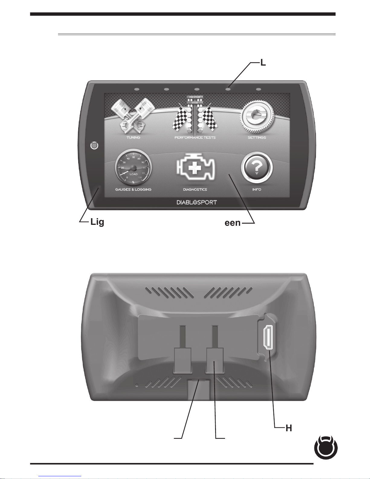
7
Quick Start
In-Cab Display
Mount
Receptacle
USB Port
HDMI
Port
Light
Sensor
LEDs
Touch Screen
Page 8
8
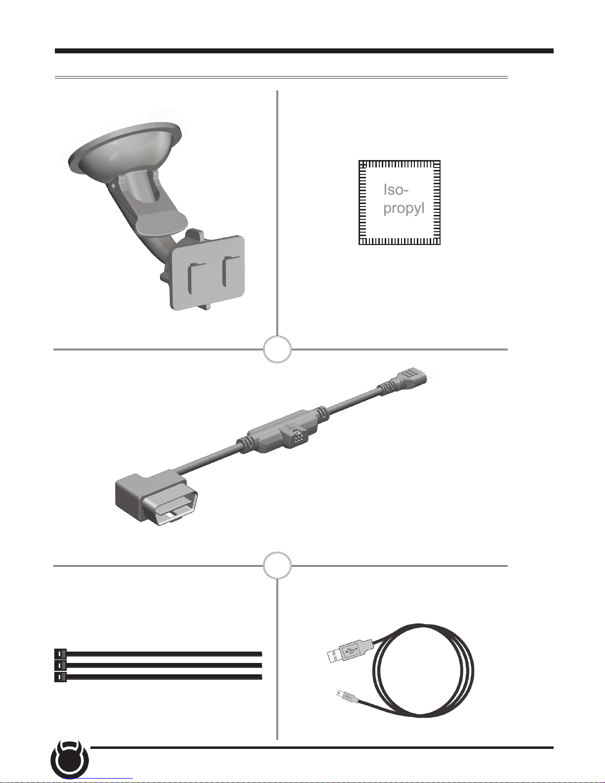
Accessories
Iso-
propyl
Windshield Suction Mount Alcohol Wipe
OBDII to HDMI Cable
OBDII
EAS
HDMI
Zip Ties
USB Cable
Page 9
9
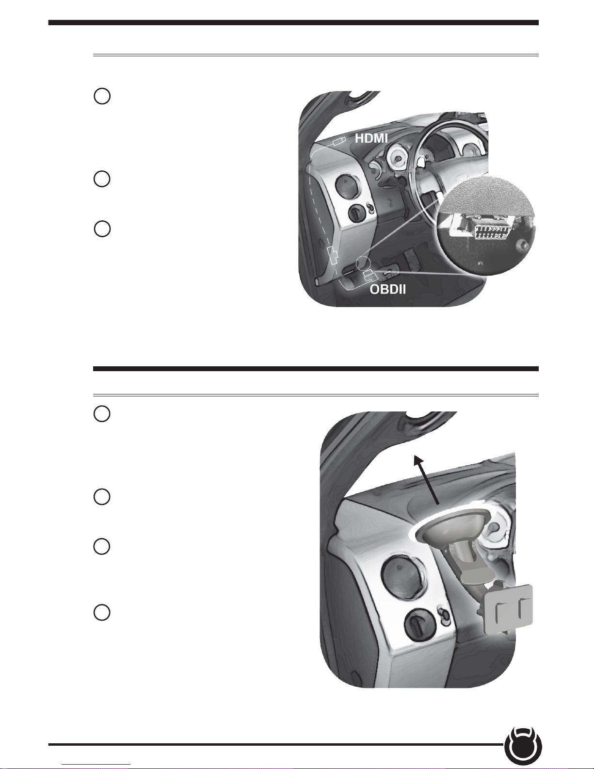
Cable Installation
1 Locate the OBDII port. The
connector is typically found
directly below the driver side
dash console.
2 Plug the OBDII connector into
the vehicle port.
3 Route the HDMI end up the
driver side dash. (On most
vehicles, the side panel may
be removed to expose the
underside of the dash for easier
routing. Leave exposed until
after the display is installed.)
Windshield Mount Installation
1 Use the alcohol wipe to clean
the windshield in the area you
plan to place the suction cup.
Allow the glass to fully dry.
2 Firmly press and hold the
suction mount against the glass.
3 Rotate the Cam Lever
towards the glass to create the
suction.
4 Plug the HDMI connector
into the back of the device
and mount the device onto the
mount.
Page 10

10
Touch Screen
Press/Select Vertical Swipe
Use these gestures to navigate and control the display.
Drag up or down menus, and
scroll through menu items.
Select options, input values, enter menus, etc.
Horizontal Swipe
Scroll through gauge screens
or change option values.
Double Tap
1
2
Enter sub-menus such as
gauge editor.
Page 11
11
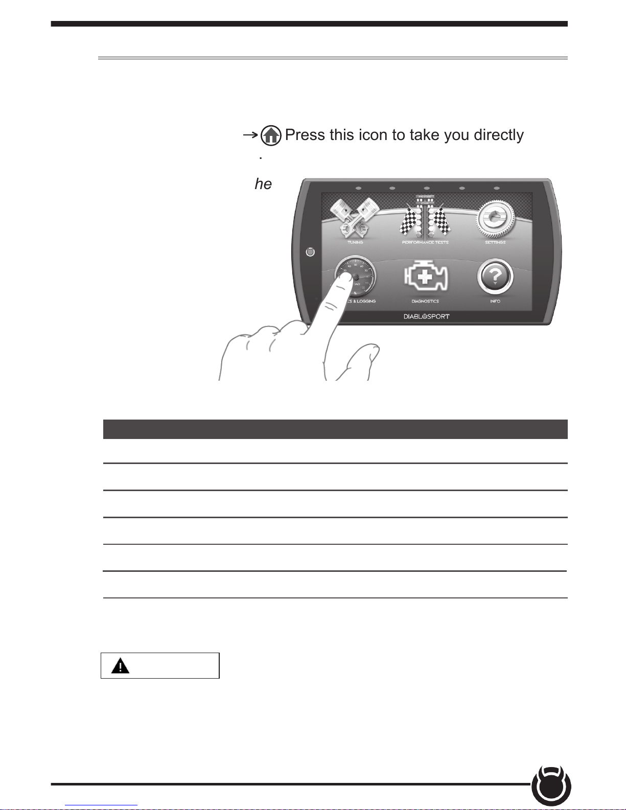
Main Menu
The Main Menu displays each of the menu options available
on your device. While navigating the menus, you will notice
the Main Menu icon. Press this icon to take you directly
back to the Main Menu.
To navigate to one of the
6 menu options, simply
select an option icon.
Menu Options Basic Descriptions
Choose from standard or *custom* tuning options.
Quickly and easily test your new tunes & performance.
Adjust device settings to better t your needs.
Tuning
Performance Tests
Settings
Diagnose and clear trouble codes.Diagnostics
Monitor and record your vehicle performance.Gauges & Logging
View & access device, tutorials, & tech support info. Info
WARNING
Misapplication or misuse of this product could lead
to a serious or fatal accident. Comply with all safety information in this
manual, and your vehicle owner’s manual. Follow safety, installation and
operating instructions in this User Manual to assure proper use.
*EX Platinum Only*
Page 12
12
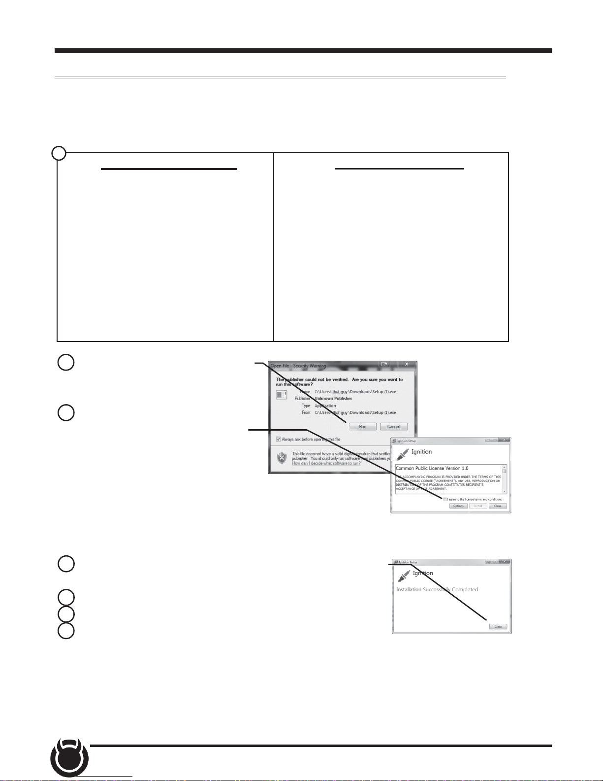
Update Software
Downloading Ignition
The Ignition Updater may be used to update the device via the USB
connection. The software may be downloaded to the computer
using either the internet, or a downloader installed on the device.
A) Go to website.
B) Click the DOWNLOADS tab
located at the top of the page.
C) Select the DOWNLOAD
IGNITION FOR PC (or MAC)
button.
A) Connect the device to a computer
using the supplied USB cable.
B) Browse the le explorer and
locate the t2 drive.
C) Double-click the drive and open
the folder labeled “Updater”.
D) Inside the Updater folder, double click the Mac or Windows folder
depending on the computer type.
E) Double-click the IgnitionInstaller.
Method 1 - Internet
Method 2 - Device
2 Click the RUN button on the
pop-up menu.
3 Read and click the box to
accept the license agreement
terms, then select INSTALL.
NOTE: If you are asked to
install the Universal Serial
Bus, Click the Install button to
continue.
4 Select the CLOSE button after the installation has
successfully completed.
5 Double-click the Ignition desktop icon.
6 Fill out the registration form.
7 Refer to the next section for performing product
update.
NOTE: DiabloSport makes updates available periodically to add coverage and
features. Updates could include a new version of update software. When you
elect to update, please refer to “Download” tab and follow instructions for T2
updates in the event software should upgrade, change names, etc.
1
Page 13

13
Product Updates
1 Double-Click the Ignition Icon located on the computer desktop.
2 Connect device to the computer using the supplied USB Cable.
(Ignition will automatically search for updates related to the device.)
3 Click the Update button.
(The update process will start and nish automatically. Once the
update is complete, you may be directed to the Online Store. To
further update your device using the online store, refer to the
following steps.)
4 Click on any or all of the available options.
(A check mark will appear in the upper right corner.)
5 Click the Purchase button.
6 If required, read and Accept the disclaimer.
7 Fill in the required information and click Go to Review.
(Here you can check the info you entered before submitting.)
8 Click the Place Order button to complete you order.
9 If a purchase was made, follow steps 1-3 above to complete the
update.
This device has the ability to update via a USB connection or
a wireless connection. Refer to the following information for
USB updates. Refer to the Check for Updates feature under the
Settings section for more information on wireless updates.
1
2
NOTE: A warranty is available to protect the hardware and mechanical
components of your Trinity 2 device in the Online Store.
Page 14

14
Tuning
Tune Vehicle
While in the Main Menu, select the Tuning icon.
The tune vehicle option provides a list of tunes selected for your vehicle’s
engine and transmission (transmission tunes available only on certain
applications).
1 Select the Tune
Vehicle option. Scroll
up/down to browse the
available tunes.
2 Select a tune to
begin the programming
sequence. Follow the
on screen instructions.
TIP: For information on
how the tune functions
click the information
icon next to the tune
name.
NOTE: The device will
proceed to read your
vehicle’s stock les and
save them for future
use.
3 Select Install to
apply the tune as is
or refer to step 6 to
customize.
4 Choose Accept and
Install to continue. The
programming sequence
will begin.
1
2
4
NOTICE Do not remove or bump the OBD-II connector during any
programming sequence. If you do, the vehicle may not start.
Page 15

15
5 Once your vehicle has been successfully tuned, press Continue to
return to the main menu.
Customization
6 Refer to steps 1
& 2 then select the
Customization option.
7 Scroll up/down to
view the available
parameters. Select an
option to modify.
7
9
8 Modify the parameter
using the tools provided
in the menu option. Select Save to apply the changes.
Tool Examples:
On/O Toggle Buttons
Plus/Minus Buttons
Key Pads
8
NOTE: Not all features are available on every make, model, and engine.
WARNING
Do not program the vehicle while parked in unsafe
locations including heavy trac or places without cell phone service and
the internet (if possible).
9 Once the parameters have been adjusted, choose Install to continue.
Toggle button may also be used
to Disable/Enable features.
Page 16

16
1 While in the
Performance Tuning
menu, select the
Restore Vehicle
option.
2 Follow the
on-screen instructions.
3 Once your vehicle
has been successfully
restored, press
Continue to go back to
the main menu.
Restore Vehicle
Use this option to return the vehicle back to it’s stock tune.
10 Next, choose
Accept and Install.
The programming
sequence will begin.
11 Once your vehicle
has been successfully
tuned, press Continue
to return to the main
menu.
10
1
Page 17

17
Custom Tuning (EX Platinum)
In order to apply custom calibrations using the custom tuning option,
you will need to contact a professional calibrator (dealer) with access to
our custom tuning software. For more information, contact our Technical
Support department or visit our website.
To get started, the dealer will request a stock le. Follow these
instructions to read and create this le:
1 Connect the device to the vehicle using the HDMI cable. Allow the
device to boot up.
2 While in the Main Menu, select the Tuning icon
3 In the Performance
Tuning menu, select
the Custom Tuning
option.
4 Next, select Read
Vehicle. The device
will read and store a
stock le.
5 Disconnect the device from the vehicle and connect it to a computer
using the supplied USB cable.
6 Browse the le
explorer and locate
the t2 drive.
7 Locate and open
the folder labeled
Tunes.
8 Open the subfolder
labeled with the
vehicle VIN. Copy the
les requested by the dealer and send them to the dealer. If your vehicle
is equipped with a PCM and TCM, there will be two pairs of les.
3
Page 18

18
Once you have a custom tune le ready to load onto the device,
refer to the following instructions:
1 Connect the device
to a computer using
the supplied USB
cable.
2 Browse the le
explorer and locate
the t2 drive.
3 Paste custom tune
le into the main t2
drive folder as shown.
NOTE: The custom tune le must be placed in this exact location in
order for the device to read and import it. Once the device recognizes it
and imports it automatically, you will recieve verication on the screen
stating that “Custom Tune for VIN.... has been loaded.
4 Disconnect the device from the computer and connect it to the
vehicle using the HDMI connection.
5 While in the Main Menu, select the Tuning icon
6 In the Performance Tuning menu, select the Custom Tuning
option.
7 Select Install Tune.
7
Page 19

19
8 Select the custom le then click Install.
9 Choose Accept and
Install to continue.
The programming
sequence will begin.
10 Once your vehicle
has been successfully
tuned, press Continue
to return to the main
menu.
8
Page 20

20
Performance Tests
0-60, 0-100, 1/4 Mile, & 1/8 Mile Tests
While in the Main Menu, select the Performance Tests icon.
A list of tests will appear. Use the following information to learn
more about each test.
PERFORMANCE TESTS
0-60 Test
0-100 Test
1/4 Mile Test
1/8 Mile Test
EXIT
1 Select the
Performance Test that
you would like to start.
00:00 000
Drag Tree
2 When the vehicle
is in place, select
the Start button to
initiate the drag tree
sequence.
3 Once the two green
lights are lit up, release
the brake and proceed
to accelerate.
0 TO 60
NOTE: There are two ways to perform these tests. The use of a drag
tree, or a stop light. Refer to the following for more information.
2
3
NOTE: The time gauge
will read JUMP if you’ve
started before the
drag timer completed
its countdown. If this
occurs select RESET
and start over.
TIP: Select the back arrow
to return to the main menu.
1
Page 21

21
00:00
From Stop
4 Switch methods by
clicking the middle
button.
5 When the vehicle is
in place, release the
brake and proceed to
accelerate.
00000:00
START
TIP: Select the back arrow
to return to the main
menu.
NOTE: Once the speed has been reached, the test will stop and the
results will be displayed. A digital drag slip will be created providing run
information such as reaction time, speed at specic distances, and other
useful information.
WARNING
Do not exceed legal speed limits on public roadways.
WARNING
Running performance tests with this product should
only be conducted in closed circuit, legally sanctioned
racing environments expressly for this purpose. Violating trac laws is
dangerous and could result in injury or vehicle damage or both.
Page 22

22
Settings
While in the Main Menu, select the Settings icon.
A list of settings will appear. This section explains what these
settings are and how to use them.
1 Select the Display
Settings option.
2 Modify each setting
by adjusting it’s
corresponding slider
left or right.
Display & Audio Settings
SETTINGS
Help/Info
Display Settings
Audio Settings
WiFi Setup
EXIT
1
2
Display Settings:
Day Mode Brightness
Adjust the display
brightness for day-light
driving.
Night Mode Brightness
Adjust the display
brightness during nighttime or low-light driving.
Day/Night Threshold
Adjust the threshold of
when day mode turns to
night mode.
LED Brightness Adjust the brightness of the 5 device LEDs.
3 Select the Audio
Settings option.
4 Turn On/O the
global Alert and Touch
sounds
Red = OFF
Green = ON
4
5
5
4
4
3
5 Press Exit to return to the main settings menu.
Page 23

23
WiFi Setup
SETTINGS
Help/Info
Display Settings
Audio Settings
WiFi Setup
EXIT
1 Select the WiFi
Setup option. A list of
available networks will
appear.
2 Select the network
that you would like to
connect the device to.
A green check mark
will appear when the
device is connected.
1
2
This device is equipped with the ability to connect to and update over
a secure WiFi connection. For more information on how to check for
updates, refer to the Check for Updates section of this manual.
TIP: Select the back arrow
to return to the gauges.
3 Use the keypad
to enter the network
password, then press
Enter. Note that most
networks are case
sensitive.
3
Page 24

24
Check for Updates
If the device is connected to WiFi, click this option to look online for
updates. If updates are available, the device will provide the option to
perform the update.
1 Select the Check
for Updates option.
If connected to
WiFi, the device will
locate our server
and download any
available updates. If
WiFi is disconnected,
the device will prompt
you to congure a
network rst.
2 Select Continue to
install the updates.
3 Follow the on
screen instructions to
completed the update
process.
SETTINGS
WiFi Setup
Check for Updates
Unit of Measure
Restore Default Settings
EXIT
1
2
Page 25

25
Unit of Measure
1 Select the Unit of
Measure option.
SETTINGS
WiFi Setup
Check for Updates
Unit of Measure
Restore Default Settings
EXIT
1
Use this setting to globally modify the device to determine whether it
uses Imperial or Metric units.
2 Select the
applicable unit of
measure.
NOTE: You will need
to unplug the device
for the changes to
take aect. DO NOT
unplug the device
while driving.
Which unit of measure would you like to use
for the gauges?
IMPERIAL METRICBACK
2
Page 26

26
Restore Default Settings
SETTINGS
Unit of Measure
Restore Default Settings
Restore Default PIDs
Alert Settings
EXIT
1
Use this setting to restore the device back to the factory settings.
1 Select the Restore
Default Settings
option.
2 Press continue
to restore all user
settings to the factory
default values.
NOTE: This will NOT restore your vehicles’ factory data or unmarry the
tool from your vehicle.
Restore Default PIDs
NOTE: You will need to unplug the device for the changes to take aect.
Use this setting to restore the default PID list.
NOTE: This will NOT restore your vehicles’ factory data or unmarry the
tool from your vehicle.
SETTINGS
Unit of Measure
Restore Default Settings
Restore Default PIDs
Alert Settings
EXIT
1
1 Select the Restore
Default PIDs option.
2 Press continue to
restore the default
PID list.
Page 27

27
Alert Settings
Use this setting to globally turn on/o gauge alerts
SETTINGS
Unit of Measure
Restore Default Settings
Restore Default PIDs
Alert Settings
EXIT
1
1 Select the Alert
Settings option.
2 Turn the setting
ON or OFF using the
toggle switch.
3 Select Exit to
return to the Settings
menu.
2
Page 28

28
Gauge Layouts
While in the Main Menu, select the Gauges & Logging icon.
The rst of 3 gauge layouts will be displayed. To toggle
between screen layouts, swipe the screen Left/Right.
Gauges & Logging
To edit the Gauge Layouts:
1 Open the pull down menu by swiping downward
starting from the top of the screen.
2 Select Edit Layout.
1
2
TIP: Open the pull up menu by swiping
upward starting from the bottom of the screen.
Page 29

29
3 Once the Layout Editor is open,
select one of the 3 layouts.
4 Toggle through the screen
style options by either swiping the
image up/down, or selecting the
up/down arrows.
5 Press the Select button to
choose the new layout style. You
will be brought back to the Layout
Editor screen.
6 Press the Save button on the
Layout Editor screen. You will be
given the option to Save as new
Layout. Use the keypad to enter
a name for your custom layout
then press Enter.
TIP: Select the Trash Can
icon to delete the current
layout settings.
TIP: Save & load factory or custom layouts.
6
4
4
5
3
TIP: The Reset Layout option resets
the layout to the factory default, including pid selections.
TIP: Select the back arrow
to return to the gauges.
Page 30

30
Theme Settings
1 While the Gauge Screen is in view. Open
the pull down menu by swiping downward
starting from the top of the screen.
2 Select Theme Settings.
1
2
Change and modify individual gauge element colors & transparency.
3 The following editor will show. Modify each of the available items by
clicking on it and selecting a new color.
4 Select Save to apply the changes.
3
4
TIP: Select the back arrow
to return to the gauges.
TIP: Touch the
gauges to view
them in their normal,
warning, and alert
states.
Page 31

31
Wallpaper
Change the background image displayed on the device.
1 While the Gauge Screen is in view. Open the pull down menu by
swiping downward starting from the
top of the screen.
2 Select Wallpaper.
1
2
3 Toggle through the available background images by either swiping up/
down on the image, or using the up/down arrows.
4 Press the Select button to apply the background image.
4
3
3
TIP: Select the back arrow
to return to the gauges.
Page 32

32
Individual Gauge Setup
Each gauge within a gauge layout can be modied individually. Settings
such as Unit of Measure, PIDs, Alert Settings, & Tick Marks may be
modied.
1 While the
gauge screen
is in view,
Double Tap
the individual
gauge to be
modied.
2 Select a PID
group from the
provided list.
Swipe up/down
to see the entire list.
3 Next, select a PID
to be displayed. A
green check mark will
appear next to the
selected PID.
4 If the PID measures
temperature or speed,
use the provided
toggle switch to
change between
Metric or Imperial
units.
5 Select Save to
apply the changes.
PID Selection:
2
TIP: Select back arrow to
return to the gauges.
4
3
5
TIP: Select the back arrow
to return to PID groups.
1
2
TIP: The Information
icon provides more detail
regarding the PID.
Page 33

33
1
2
3
1 Select the icon.
2 Use the (3) toggle
buttons to toggle each
option on/o.
Alert Settings:
Alerts On/O
Alert sounds On/O
Warning areas On/O
TIP: Select the back arrow
to return to the gauges.
3 To adjust the warning and alert values for the PID, use the respective
sliders.
4 Select Save to apply the changes.
Tick Mark Customization:
1
2
3
1 Select the icon.
2 Adjust the number
of Major Tick Marks
visible on the gauge.
3 Adjust the number
of Minor Tick Marks
visible on the gauge.
4 Select Save to apply
the changes.
TIP: Select the back arrow
to return to the gauges.
4
4
Page 34

34
Recording
Use the recording option to log and save vehicle data.
1 While the Gauge Screen is in view. Open the pull down menu by
swiping downward starting from the top of the screen.
2 Press the Record button to start the recording process. When the
desired amount of information has been gathered, press the Stop button.
1
2
Record Stop
DataViewer Download
This windows software allows OBDII data logs that were recorded with
the DiabloSport tuner to be opened and viewed. This software can be
downloaded from the DiabloSport website.
1 Go to website.
2 Click the DOWNLOADS tab located at the top of the page.
3 Select the DOWNLOAD button under DataViewer.
4 Click the RUN button on the pop-up menu.
5 Follow the on-screen instructions.
NOTE: The LED
above the recording
icon will shine blue
during the
recording.
Page 35

35
DataViewer
After a recording session, unplug the device from the vehicle and follow
these instructions.
1 Double-Click the
DataViewer icon
located on your
computer desktop.
2 Connect the device
to the PC using a USB
connector.
3 Select the icon
and browse to the T2
drive.
4 Open the logs folder. Select the log le you would like to open and
click the open button to continue.
5 Toggle on/o information
using the check boxes.
TIP: For more information
on DataViewer functionality
open the Help menu.
Page 36

36
Diagnostics
Trouble Codes
While in the Main Menu, select the Diagnostics icon.
The trouble codes screen will appear. If any codes have been
initiated, they will show in the list as a P###.
NOTE: Trouble codes are created when an issue is detected by vehicle
sensors. Use this feature to view and clear these trouble codes.
1 If a code has been initiated, select the code to see a description of the
issue.
TIP: Write the codes down for future reference.
2 Once you have read the code(s) description, you have the option to
clear them. Select Clear All to clear the codes from the device and reset
the vehicle’s check engine light.
TROUBLE CODES
CLEAR ALL
P0107
P0122
1
2
TIP: Select the back arrow
to return to the main menu.
NOTE: If a DTC persists, this could indicate a vehicle malfunction, We
recommend seeking a qualied professional in resolving the issue.
Program the vehicle back to stock prior to service.
Page 37

37
Help/Info
Device Info
While in the Main Menu, select the Info icon.
The device info described below assists our Tech Support team
when support is needed.
HELP/INFO
Device Info
Tutorials
F.A.Q’s
Tech Support
EXIT
1 Click the Device Info option. The following information will appear:
Application Info - Gives version information for the various applications
running on the device.
Database Info - Gives version information for the various databases
stored on the device such as Tunes, PIDs, and DTC codes.
Tool Info - Gives information about the device such as the serial
number, born date, licenses, tool type, etc.
Vehicle Info - Information about the vehicle such as the vehicle
identication number (VIN) and Engine Control Module (ECM).
Tuned Vehicle Info - Information about the vehicle that this device has
tuned such as the VIN and ECM.
Debian - Information about the Linux Debian build the device is using.
Open SSL - Information about the Open SSL
Boost - Information about Boost software.
FCC - Information about FCC compliance.
1
TIP: Select Exit to
return to the main
menu.
Page 38

38
Tutorials
HELP/INFO
Device Info
Tutorials
F.A.Q’s
Tech Support
EXIT
1
All of the available tutorials are stored here and can be accessed at any
time.
1 Select the Tutorials
option.
2 View each tutorial
by swiping left/right.
3 Select Continue to
return to the Help/Info
menu.
F.A.Q’s
Displays and answers a few frequently asked questions about the device
and it’s features.
HELP/INFO
Device Info
Tutorials
F.A.Q’s
Tech Support
EXIT
1
1 Select the F.A.Qs
option. A list of
questions and answers
will appear.
TIP: Select Exit to
return to the main
menu.
Page 39

39
Tech Support
This option is to be used only when Tech Support requests information.
NOTE: When a menu item is selected, a set of “keys” will be given. Tech
Support will use these keys to produce a code that you will use to access
the menu items functionality.
HELP/INFO
Device Info
Tutorials
F.A.Q’s
Tech Support
EXIT
1
TECH SUPPORT
Force Calibration Update
Force Restore
Vehicle Reset
Clear Updates
EXIT
1 Select the Tech
Support option. A
list of questions and
answers will appear.
2 Select the menu
item as required by
Tech Support.
2
TIP: Select Exit to
return to the main
menu.
Force Calibration Update - This option programs the vehicle with the
stock calibration le. It is useful for recovering problematic ECUs.
Force Restore - This option will program the vehicle with a preciously
saved stock le. It is also useful for recovering problematic ECUs.
Vehicle Reset - Erases all vehicle specic information from the device.
Clear Updates - Erases any agged calibration updates for the ECU.
Registry Reset - Erase all cached vehicle information from the device.
Generate Log - Write any cached debug information to a debug le that
can be retrieved from the public folder.
Shop for other performance chips and programmers on our website.
 Loading...