


RPM3™
Reference Pressure Monitor
Operation and Maintenance Manual
© 1998-2002 DH Instruments, Inc.

High pressure liquids and gases are potentially hazardous. Energy stored in these liquids and gases
can be released unexpectedly and with extreme force. High pressure systems should be assembled
and operated only by personnel who have been instructed in proper safety practices.
© 1998-2002 DH Instruments, Inc. All rights reserved.
Information in this document is subject to change without notice. No part of this document may be reproduced or transmitted in any
form or by any means, electronic or mechanical, for any purpose, without the express written permission of DH Instruments, Inc.
4765 East Beautiful Lane Phoenix AZ 85044-5318 USA.
DH Instruments makes sincere efforts to ensure accuracy and quality of its’ published materials; however, no warranty, expressed
or implied, is provided. DH Instruments disclaims any responsibility or liability for any direct or indirect damages resulting from the
use of the information in this manual or products described in it. Mention of any product or brand does not constitute an
endorsement by DH Instruments of that product or brand. This manual was originally composed in English and was subsequently
translated into other languages. The fidelity of the translation cannot be guaranteed. In case of conflict between the English version
and other language versions, the English version predominates.
Products described in this manual are manufactured under international patents and one or more of the following U.S. patents:
5,142,483, 5,257,640, 5,331,838, 5,445,035. Other U.S. and international patents pending.
DH Instruments, DH, DHI, AutoZ, COMPASS, CalTool, PPC, PPC2+, RPM3 and SDS (Self Defense System) are trademarks,
registered and otherwise, of DH Instruments, Inc.
LabVIEW is a registered trademark of National Instruments Corporation.
Document No. 550094f-01
020909
Printed in the USA.
© 1998-2002 DH Instruments, Inc.

TABLE OF CONTENTS
T
AABBLLEE
T
O
O
FF
C
OONNTTEENNTTS
C
S
TABLE OF CONTENTS ...............................................................I
TABLES .................................................................................IV
FIGURES.................................................................................V
ABOUT THIS MANUAL .............................................................VI
1. INTRODUCTION .................................................................1
1.1 PRODUCT OVERVIEW ...........................................................................................................................1
1.2 SPECIFICATIONS ...................................................................................................................................1
1.2.1 GENERAL SPECIFICATIONS.......................................................................................................................1
1.2.2 PRESSURE MEASUREMENT SPECIFICATIONS........................................................................................2
1.2.2.1 STANDARD REFERENCE PRESSURE TRANSDUCER (RPT) ...............................................................3
1.2.2.2 B TYPE REFERENCE PRESSURE TRANSDUCER (RPT) ......................................................................4
1.2.2.3 ON-BOARD BAROMETER ........................................................................................................................4
1.2.3 CONFIGURATIONS.......................................................................................................................................5
1.2.3.1 ONE OR TWO RPTS: GROUP 1 (< A1500) .............................................................................................6
1.2.3.2 TWO RPTS: ONE GROUP 1 (> A1500) AND ONE GROUP 2 (> A1500 AND < A10000) OR ONE
1.2.3.3 TWO RPTS: BOTH GROUP 2 (> A1500 AND < A10000) OR LIQUID FILLED GROUP 1.......................8
1.2.3.4 ONE RPT: GROUP 2 (> A1500 AND > A10000) OR GROUP 3 (> A10000) OR LIQUID FILLED
LIQUID FILLED GROUP 1 .........................................................................................................................
GROUP 1 ...................................................................................................................................................
7
9
2. INSTALLATION ................................................................ 11
2.1 UNPACKING AND INSPECTION ..........................................................................................................11
2.1.1 REMOVING FROM PACKAGING................................................................................................................11
2.1.2 INSPECTING CONTENTS...........................................................................................................................11
2.2 SITE REQUIREMENTS..........................................................................................................................11
2.3 INITIAL SETUP......................................................................................................................................12
2.3.1 PREPARING FOR OPERATION .................................................................................................................12
2.3.2 FRONT AND REAR PANELS ......................................................................................................................12
2.3.2.1 FRONT PANEL ........................................................................................................................................12
2.3.2.2 REAR PANEL...........................................................................................................................................13
2.3.3 POWER CONNECTION...............................................................................................................................13
2.3.4 TEST PORT CONNECTING ........................................................................................................................13
2.3.4.1 THE ATM AND VENT PORTS .................................................................................................................14
2.4 POWER UP AND VERIFICATION .........................................................................................................15
2.4.1 APPLY POWER...........................................................................................................................................15
2.4.2 CHECK PROPER PRESSURE MEASUREMENT OPERATION ................................................................15
2.4.2.1 CHECKING ABSOLUTE MODE PRESSURE MEASUREMENT.............................................................15
2.4.2.2 CHECKING GAUGE MODE PRESSURE MEASUREMENT...................................................................16
2.5 SHORT TERM STORAGE .....................................................................................................................16
3. OPERATION..................................................................... 17
3.1 GENERAL/MANUAL OPERATION .......................................................................................................17
3.1.1 MAIN RUN SCREEN....................................................................................................................................17
3.1.2 GENERAL OPERATING PRINCIPLES .......................................................................................................18
3.1.2.1 KEYPAD LAYOUT AND PROTOCOL......................................................................................................18
3.1.2.2 SOUNDS ..................................................................................................................................................18
3.1.2.3 SOFT [ON/OFF] KEY ...............................................................................................................................19
3.1.2.4 PRESSURE READY <*>/NOT READY (<↑> OR <↓>)...........................................................................19
3.1.2.5 MULTIPLE PRESSURE RANGES...........................................................................................................19
3.1.2.6 SDS SELF DEFENSE SYSTEM ..............................................................................................................20
Page I © 1998-2002 DH Instruments, Inc.

RPM3™ OPERATION AND MAINTENANCE MANUAL
3.1.2.7 DIRECT FUNCTION KEYS SUMMARY...................................................................................................21
3.2 3.2 DIRECT FUNCTION KEYS ..............................................................................................................22
3.2.1 3.2.1 [RANGE] .............................................................................................................................................22
3.2.2 [UNIT]...........................................................................................................................................................24
3.2.3 [MODE] ........................................................................................................................................................25
3.2.4 [UL] (UPPER LIMIT) ....................................................................................................................................26
3.2.4.1 OVER-PRESSURE FUNCTION (PMAX!) ................................................................................................27
3.2.5 [RES] (RESOLUTION).................................................................................................................................28
3.2.6 [DISPLAY]....................................................................................................................................................29
3.2.6.1 AVG (AVERAGE) .....................................................................................................................................30
3.2.6.2 RATE........................................................................................................................................................31
3.2.6.3 DEV (DEVIATION) ...................................................................................................................................32
3.2.6.4 RPT ..........................................................................................................................................................33
3.2.6.5 HI/LO ........................................................................................................................................................34
3.2.6.6 FREEZE ...................................................................................................................................................35
3.2.6.7 CLEAN .....................................................................................................................................................35
3.2.7 [HEAD].........................................................................................................................................................36
3.2.8 [SDS] (SELF DEFENSE SYSTEM) .............................................................................................................37
3.2.9 [AUTOZ].......................................................................................................................................................40
3.2.9.1 RUNNING AUTOZ IN GAUGE MEASUREMENT MODE ........................................................................40
3.2.9.2 RUNNING AUTOZ IN ABSOLUTE MEASUREMENT MODE..................................................................41
3.3 [SETUP] MENU KEY .............................................................................................................................45
3.3.1 HEAD ...........................................................................................................................................................45
3.3.2 PRESU .........................................................................................................................................................46
3.3.3 READRT (READ RATE)...............................................................................................................................47
3.3.4 STAB (STABILITY)......................................................................................................................................48
3.3.5 LEAK (LEAK CHECK).................................................................................................................................48
3.4 [SPECIAL] MENU KEY..........................................................................................................................50
3.4.1 AUTOZ .........................................................................................................................................................51
3.4.1.1 AUTOZ ON/OFF.......................................................................................................................................53
3.4.1.2 VIEW AUTOZ ...........................................................................................................................................54
3.4.1.3 EDIT AUTOZ ............................................................................................................................................54
3.4.2 SDS ..............................................................................................................................................................55
3.4.3 ATM..............................................................................................................................................................56
3.4.4 REMOTE ......................................................................................................................................................56
3.4.5 RESET..........................................................................................................................................................57
3.4.5.1 RESET - SETS.........................................................................................................................................58
3.4.5.2 RESET - UNITS........................................................................................................................................58
3.4.5.3 RESET - COM..........................................................................................................................................58
3.4.5.4 RESET - CAL ...........................................................................................................................................59
3.4.5.5 RESET - ALL............................................................................................................................................59
3.4.6 CAL ..............................................................................................................................................................59
3.4.7 INTERN ........................................................................................................................................................59
3.4.7.1 SCRSAV...................................................................................................................................................60
3.4.7.2 SOUND.....................................................................................................................................................60
3.4.7.3 TIME.........................................................................................................................................................60
3.4.7.4 ID..............................................................................................................................................................61
3.4.8 LEVEL..........................................................................................................................................................62
3.4.9 LOG..............................................................................................................................................................64
4. REMOTE OPERATION ....................................................... 65
4.1 OVERVIEW ............................................................................................................................................65
4.2 INTERFACING.......................................................................................................................................65
4.2.1 4.2.1 RS-232 INTERFACE...........................................................................................................................65
4.2.1.1 4.2.1.1 COM1 ...........................................................................................................................................65
4.2.1.2 COM2 .......................................................................................................................................................66
4.2.2 IEEE-488 (GPIB)..........................................................................................................................................66
4.3 REMOTE COMMAND SYNTAX AND STYLE .......................................................................................66
4.3.1 LOCAL AND REMOTE SETTING................................................................................................................66
4.3.2 COMMAND SYNTAX...................................................................................................................................66
4.3.3 QUERIES AND REPLIES ............................................................................................................................67
4.3.4 MULTIPLE COMMANDS .............................................................................................................................67
4.3.5 COMMAND PARAMETERS.........................................................................................................................67
4.3.6 SUFFIXES....................................................................................................................................................68
4.3.7 PROGRAMMING TIPS.................................................................................................................................68
4.3.7.1 SCPI AND IEEE-488.2 .............................................................................................................................68
4.3.7.2 PROGRAM TECHNIQUE.........................................................................................................................68
4.4 COMMANDS ..........................................................................................................................................72
4.4.1 ERROR MESSAGES 75
© 1998-2002 DH Instruments, Inc. Page II

TABLE OF CONTENTS
4.4.2 COMMAND DESCRIPTIONS.......................................................................................................................76
4.4.2.1 IEEE STD. 488.2 COMMON AND STATUS COMMANDS ......................................................................76
4.4.2.2 MEASUREMENT SUBSYSTEM ..............................................................................................................78
4.4.2.3 CALCULATE SUBSYSTEM .....................................................................................................................81
4.4.2.4 CALIBRATION SUBSYSTEM ..................................................................................................................82
4.4.2.5 DISPLAY SUBSYSTEM ...........................................................................................................................84
4.4.2.6 SENSE SUBSYSTEM..............................................................................................................................84
4.4.2.7 STATUS SUBSYSTEM ............................................................................................................................86
4.4.2.8 SYSTEM SUBSYSTEM............................................................................................................................90
4.4.2.9 UNIT SUBSYSTEM..................................................................................................................................94
4.5 STATUS SYSTEM .................................................................................................................................96
4.5.1 STATUS REPORTING SYSTEM .................................................................................................................96
4.5.1.1 SCPI STATUS SUBSYSTEM...................................................................................................................96
4.5.1.2 ERROR QUEUE.......................................................................................................................................96
4.5.1.3 STATUS BYTE REGISTER......................................................................................................................97
4.5.1.4 STANDARD EVENT REGISTER .............................................................................................................98
4.5.1.5 RPT READY STATUS REGISTER ..........................................................................................................99
4.5.2 STATUS SUBSYSTEM..............................................................................................................................100
4.5.2.1 OPERATION REGISTER STRUCTURE................................................................................................100
4.5.2.2 QUESTIONABLE REGISTER STRUCTURE.........................................................................................103
5. MAINTENACE, ADJUSTMENTS AND CALIBRATION .............107
5.1 INTRODUCTION ..................................................................................................................................107
5.2 CALIBRATION OF REFERENCE PRESSURE TRANSDUCERS.......................................................107
5.2.1 PRINCIPLE ................................................................................................................................................107
5.2.1.1 PA/PM COEFFICIENTS.........................................................................................................................108
5.2.1.2 SETTING ZNATERR..............................................................................................................................108
5.2.1.3 ORDER OF OPERATIONS....................................................................................................................109
5.2.2 EQUIPMENT REQUIRED ..........................................................................................................................109
5.2.3 SET-UP AND PREPARATION...................................................................................................................110
5.2.4 RPT CALIBRATION USING CALTOOL FOR RPTS SOFTWARE............................................................111
5.2.5 EDITING AND VIEWING RPT CALIBRATION INFORMATION................................................................ 111
5.2.6 SETTING ZNATERR..................................................................................................................................112
5.2.7 RPT CALIBRATION/ADJUSTMENT WITHOUT CALTOOL FOR RPTS SOFTWARE.............................113
5.3 ADJUSTMENT OF ON-BOARD BAROMETER...................................................................................114
5.4 OVERHAUL .........................................................................................................................................114
5.5 RELOADING EMBEDDED SOFTWARE INTO FLASH MEMORY......................................................115
5.6 SUBASSEMBLY DESCRIPTION AND LOCATION ............................................................................116
5.6.1 INTERNAL VIEW .......................................................................................................................................116
5.6.1.1 SDS MODULE........................................................................................................................................116
5.6.1.2 RPTS......................................................................................................................................................117
5.6.1.3 POWER SUPPLY...................................................................................................................................117
5.6.1.4 COOLING FAN.......................................................................................................................................117
5.6.1.5 MICRO BOARD......................................................................................................................................117
5.6.1.6 MAIN BOARD.........................................................................................................................................117
5.6.1.7 ON-BOARD BAROMETER ....................................................................................................................117
5.6.1.8 DISPLAY ................................................................................................................................................117
6. TROUBLESHOOTING .......................................................119
6.1 OVERVIEW ..........................................................................................................................................119
7. APPENDIX ......................................................................123
7.1 PRESSURE UNIT CONVERSIONS .....................................................................................................123
7.2 WARRANTY STATEMENT.................................................................................................................. 124
8. GLOSSARY.....................................................................125
Page III © 1998-2002 DH Instruments, Inc.

RPM3™ OPERATION AND MAINTENANCE MANUAL
T
AABBLLEES
T
Table 1 Standard RPT Designations and Ranges....................................................................................... 3
Table 2 b Type RPT Designations and Ranges ..........................................................................................4
Table 3 RPM3 Configurations...................................................................................................................... 5
Table 4 One or Two RPTs: Group 1 (> A1500) Specifications................................................................... 6
Table 5 Two RPTs: One Group 1 (> A1500) and One Group 2 (> A1500 and < A10000)
Table 6 Two RPTs: Both Group 2 (> A1500 and < A10000) or Liquid Filled Group 1 Specifications........ 8
Table 7 One RPT: Group 2 (> A1500 and < A10000) or Group 3 (> A10000) or
Table 8 RPM3 Parts List ............................................................................................................................ 11
Table 9. RPM3 Range Identification Summary.......................................................................................... 20
Table 10 Summary of RPM3 Direct Function Key Operation .................................................................... 22
Table 11 PresU - Available Units ............................................................................................................... 46
Table 12 READRT - Display Update Rates ............................................................................................... 47
Table 13. Functions - Security Levels........................................................................................................63
Table 14 RPM3 COM1 DB-9F Pin Designations ....................................................................................... 65
Table 15 IBM PC/XT DB-9F, DB-9M Connections ....................................................................................65
Table 16 RPM3 COM2 DB-9M Pin Designations ......................................................................................66
Table 17 Quick Tips ...................................................................................................................................71
Table 18 Command Summary ................................................................................................................... 72
Table 19 “SYSTEM:ERROR?” QUERY REPLY ........................................................................................ 75
Table 20 8 Bit Status Byte Register ........................................................................................................... 97
Table 21 Standard Event Register.............................................................................................................98
Table 22 8 Bit RPT Ready Status Register ............................................................................................... 99
Table 23. RPM3 Troubleshooting Symptom / Probable Cause / Solution List ........................................ 119
Table 24 Pa Conversions......................................................................................................................... 123
Table 25. DHI Authorized Service Providers ........................................................................................... 124
S
or One Liquid Filled Group 1 Specifications..............................................................................
Liquid Filled Group 1 Specifications ..........................................................................................
7
9
© 1998-2002 DH Instruments, Inc. Page IV

FIGURES & TABLES
F
IIGGUURREES
F
Figure 1 Rear Panel (Left) One or Two Group 1 RPTs (Right) One or Two Group 1 RPTs with
Figure 2 Schematic (Left) Two Group 1 RPTs (Right) One Group 1 RPT .................................................. 6
Figure 3 Rear Panel (Left) One Group 1 RPT and One Group 2 RPT (Right) One Group 1
Figure 4 Schematic One Group 1 RPT and One Group 2 RPT................................................................... 7
Figure 5 Two Group 2 RPTs (Left) Rear Panel / (Right) Schematic .......................................................... 8
Figure 6 Rear Panel (Left) One Group 2 RPT (Right) One Group 3 RPT ................................................... 9
Figure 7 Schematic (Left) One Group 2 RPT (Right) One Group 3 RPT .................................................... 9
Figure 8. Front Panel .................................................................................................................................12
Figure 9. Test Ports.................................................................................................................................... 13
Figure 10 Keypad.......................................................................................................................................18
Figure 11 SDS Schematic.......................................................................................................................... 21
Figure 12 Status Byte Register .................................................................................................................. 97
Figure 13 Illustration of this Structure Duplicated for Each of the OPERation, INSTrument,
Figure 14 Relationship of the OPERation Register and Its Support Registers .......................................102
Figure 15 Illustration of this Structure Duplicated for Each of the OPERation, INSTrument,
Figure 16 Relationship of the QUEStionable Registers and Its Support Registers................................. 105
Figure 17 RPM3 Internal View ................................................................................................................. 116
S
a GXXXX RPT ...........................................................................................................................
GXXXX RPT and One Group 2 RPT.........................................................................................
and ISUMmary Registers ......................................................................................................
and ISUMmary Registers ......................................................................................................
101
104
6
7
Page V © 1998-2002 DH Instruments, Inc.

RPM3™ OPERATION AND MAINTENANCE MANUAL
A
BBOOUUTT
A
This manual provides the user with the basic information necessary to operate an RPM3, Reference
Pressure Monitor. It also includes a great deal of additional information provided to help you optimize
RPM3 use and take full advantage of its many features and functions.
Before using the manual, take a moment to familiarize yourself with the Table of Contents structure. All first
time RPM3 users should read Sections 1, 2 and 3. Section 3 provides a comprehensive description of
general RPM3 operating principles. Section 4 is for remote operation from an external computer.
Section 5 provides maintenance and calibration information. Section 6 is a quick troubleshooting guide.
Use it to troubleshoot unexpected RPM3 behavior based on the symptoms of that behavior.
Certain words and expressions have specific meaning as they pertain to RPM3. The Glossary is useful
as a quick reference for exact definition of specific words and expressions as they are used in this
manual.
FOR THOSE OF YOU WHO “DON’T READ MANUALS”, GO DIRECTLY TO SECTION 2.3 TO SET UP YOUR
RPM3 AND THEN SECTION 2.4 FOR POWER UP AND VERIFICATION. THIS WILL GET YOU RUNNING
QUICKLY WITH MINIMAL RISK OF CAUSING DAMAGE TO YOURSELF OR YOUR NEW RPM3. THEN…
WHEN YOU HAVE QUESTIONS OR START TO WONDER ABOUT ALL THE GREAT FEATURES YOU MIGHT
BE MISSING, GET INTO THE MANUAL!
T
T
HHIISS
M
AANNUUAAL
M
L
Manual Conventions
(CAUTION) is used in throughout the manual to identify user warnings and cautions.
(NOTE) is used throughout the manual to identify operating and applications advice and
additional explanations.
[ ] indicates direct function keys (e.g., [RANGE]).
< > indicates PG7000 screen displays (e.g., <1yes>).
© 1998-2002 DH Instruments, Inc. Page VI

1. INTRODUCTION
11..
I
NNTTRROODDUUCCTTIIOON
I
N
1.1 PRODUCT OVERVIEW
RPM3 is a stand-alone, microprocessor driven, reference pressure monitor intended to accurately
measure gas or liquid pressure in a wide variety of pressure calibration, measurement and testing
applications. It has been designed to provide very high performance and extensive features combined
with maximum versatility and ease of use.
RPM3 uses one or two high accuracy reference pressure transducers (RPTs) and an on-board barometer
to measure pressure. Various internal configurations exist depending on the RPT ranges.
RPM3 can be controlled locally by the operator using its front panel display and keypad or remotely by a
computer using ASCII character command strings over its RS-232 and IEEE-488 interfaces.
RPM3 models are available to measure pressure in ranges from 0.6 psi (4 kPa) to 40 000 psi (275 MPa)
in gauge, compound and absolute measurement modes.
1.2 SPECIFICATIONS
1.2.1 GENERAL SPECIFICATIONS
Specifications below are specific to PG7307. All other specifications are identical to PG7000
specifications found in the PG7000 Operation and Maintenance Manual (P/N 550099).
Power Requirements
Operating Temperature Range
Storage Temperature Range
Vibration
Weight
Dimensions
Microprocessors
Communication Ports
Overall Pressure Ranges
Operating Media
85 to 264 VAC, 47 to 440 Hz, 18 VA max. consumption
15 to 35 °C
-20 to 70 °C
Meets MIL-T-28800D
3.5 kg (7.7 lb) max depending on RPT configuration
8 cm H x 22.5 cm W x 20 cm D (3.1 in. x 8.9 in. x 7.9 in.) approx.
Motorola 68302
RS-232 (COM1), RS-232 (COM2), IEEE-488
Up to six pressure ranges from 0 to 0.6 psi (4 kPa) to 0 to 40 000 psi
(275 MPa), absolute, gauge and negative gauge, using one or two
reference pressure transducers and a barometer
Any non-corrosive gas or liquid (liquid available only on A0100 or
higher RPTs). RPTs < 10 000 psi (70 MPa) delivered set up for gas
operation, RPTs >
10 000 psi delivered oil filled.
Page 1 © 1998-2002 DH Instruments, Inc.

RPM3™ OPERATION AND MAINTENANCE MANUAL
Pressure Connections
Pressure Limits
Self Defense System (SDS™)
CE Conformance
Test port (RPT ≤ 10 000 psi): 1/8 in. NPT F
Test port (RPT > 10 000 psi): DH500 (gland and collar type for
coned and left hand threaded
tube, equivalent to AE F250C,
HIP HF4, etc.)
Test (-): 1/8 in. NPT F (with gauge RPT
only)
ATM Ref (On-board barometer): 10-32 UNF
Vent (with SDS only): 10-32 UNF
Maximum working pressure: Range 3 of active RPT+ 4 %
Maximum pressure w/o damage: Standard RPT: 125 % of H3
b Type RPT: 150 % of H3
Maximum pressure applied to
SDS protected TEST port
when SDS is active: 2 000 psi (13 MPa)
Included on all gas operated RPTs of 1 500 psi (10 MPa) or lower.
Isolates RPT from TEST port and vents it to atmosphere when NOT
in use. SDS is NOT included with liquid filled RPTs.
Maximum SDS isolation pressure: 2 000 psi (13 MPa)
Available. Must be specified.
1.2.2 PRESSURE MEASUREMENT SPECIFICATIONS
RPM3 can be configured with one or two reference pressure transducers (RPT). Each
transducer has three ranges (see Section 3.1.2.5). The type and designation of the RPM3’s
RPTs determine its measurement specifications and configuration (see Sections 1.2.2 and
1.2.3). Two types of RPTs are available. Standard RPTs are for the highest measurement
specifications and b Type RPTs for lower measurement performance requirements.
All reference pressure transducers (RPTs) with designation greater than G0030 (200 kPa)
are of the absolute pressure type with an evacuated, permanently sealed reference. Absolute
RPTs can measure both absolute and gauge pressure. Gauge pressures with an absolute
RPT are defined by offsetting atmospheric pressure dynamically with compensation for
atmospheric changes by the on-board barometer. Gauge RPTs cannot measure absolute
pressure.
© 1998-2002 DH Instruments, Inc. Page 2

1. INTRODUCTION
1.2.2.1 STANDARD REFERENCE PRESSURE TRANSDUCER (RPT)
Table 1 Standard RPT Designations and Ranges
Standard RPT Measurement Specifications (% FS of Active Range)
Transducer Type
Warm Up Time
Resolution
Overpressure Limits
Without effect on calibration
Without permanent damage
Temperature Effect
Oscillating quartz resonator
≤ 1 500 psi 15 minutes
To 1 ppm, user settable by individual range
115 % of Range 3
125 % of Range 3
Fully compensated with active independent temperature
measurement from -20 to 100 °C
± 0.005 % maximum temperature effect in normal ambient operating
range of 15 to 35 °C
Attitude Affect
Precision
1
± 0.008 % /g maximum, worst axis
≤ 1 500 psi 0.005 %, > 10 500 and ≤ 20 000 psi 0.010 %,
> 20 000 psi 0.015 %
Predicted Stability
Absolute Mode (w/out Autozero)
Measurement Accuracy
Absolute Mode (w/out Autozero)
1
Precision: Combined linearity, hysteresis, repeatability of measurements made by the reference pressure transducer. When using an absolute RPT
2
Stability: Maximum change in zero and span over specified time period for typical transducer used under typical conditions. As stability can only be
3
Accuracy: Maximum deviation of the reference pressure transducer indication from the TRUE value of the applied pressure including precision,
for gauge mode measurement add ± 2.5 Pa (0.00035 psi) to the precision specification to take into account the resolution and short term
stability of the on-board barometer used for dynamic atmospheric pressure compensation.
predicted and varies from transducer to transducer, stability for a specific RPT should be established from experience.
stability, temperature effect and calibration standard accuracy of ± 0.0035 % of reading.
2
Gauge Mode (w/Autozero)
Absolute Mode (w/Autozero)
3
Gauge Mode (w/Autozero)
Absolute Mode (w/Autozero)
All Ranges
90 day / 1 yr
0.003 % / 0.009 %
0.003 % / 0.009 %
0.006 % / 0.0015 %
≤ 1 500 psi
90 day / 1 yr
0.008 / 0.012 %
0.008 / 0.012 %
0.010 / 0.017 %
> 1 500 ≤ 20 000 psi
90 day / 1 yr
0.012 / 0.015 %
0.012 / 0.015 %
0.012 / 0.020 %
> 20 000 psi
90 day / 1 yr
0.020 / 0.022 %
0.020 / 0.022 %
0.022 / 0.025 %
Page 3 © 1998-2002 DH Instruments, Inc.

RPM3™ OPERATION AND MAINTENANCE MANUAL
1.2.2.2 B TYPE REFERENCE PRESSURE TRANSDUCER (RPT)
Table 2 b Type RPT Designations and Ranges
b Type RPT Measurement Specifications (% FS of Active Range)
Transducer Type
Warm Up Time
Resolution
Overpressure Limits
Without effect on calibration
Without permanent damage
Temperature Effect
Micro-machined piezoresistive silicon
None required
10 ppm, user settable by individual range
120 % of Range 3
150 % of Range 3
Fully compensated with active independent temperature
measurement from - 40 to 85 °C
± 0.02 % maximum temperature effect in normal ambient 15 to 35 °C
operating range
Acceleration Affect
Precision
Predicted Stability
1
2
Gauge Mode (w/Autozero)
Absolute Mode (w/Autozero)
Absolute Mode (w/out Autozero)
Measurement Accuracy
3
Gauge Mode (w/Autozero)
Absolute Mode (w/Autozero)
Absolute Mode (w/out Autozero)
1
Precision: Combined linearity, hysteresis, repeatability of measurements made by the reference pressure transducer. When using an absolute RPT
2
Stability: Maximum change in zero and span over specified time period for typical transducer used under typical conditions. As stability can only be
3
Accuracy: Maximum deviation of the reference pressure transducer indication from the TRUE value of the applied pressure including precision,
for gauge mode measurement add ± 2.5 Pa (0.00035 psi) to the precision specification to take into account the resolution and short term
stability of the on-board barometer used for dynamic atmospheric pressure compensation.
predicted and varies from transducer to transducer, stability for a specific RPT should be established from experience.
stability, temperature effect and calibration standard accuracy of ± 0.0035 % of reading.
Insignificant on all axes
0.03 %
90 day / 1 yr
0.02 % / 0.03 %
0.02 % / 0.03 %
0.03 % / 0.05 %
90 day / 1 yr
0.04 % / 0.05 %
0.04 % / 0.05 %
0.05 % / 0.06 %
1.2.2.3 ON-BOARD BAROMETER
Sensor Technology
Warm Up Time
Resolution
The on-board barometer is NOT used as a source of absolute accuracy. It is
© 1998-2002 DH Instruments, Inc. Page 4
Micro-machined silicon
None required
1.25 Pa (0.00018 psi)
used only to measure changes in atmospheric pressure for dynamic
compensation of the atmospheric pressure offset when using an absolute
reference pressure transducer to make gauge pressure measurements (see
Section 3.4.1).

1. INTRODUCTION
1.2.3 CONFIGURATIONS
RPM3 rear panel and internal schematic configurations vary depending on the number (1 or 2)
and pressure ranges of the RPM3’s RPT(s). For configuration purposes, RPTs are divided
into three groups by range designation as in Table 3.
Table 3 RPM3 Configurations
RPT GROUP RPT DESIGNATIONS
1 A1500 or lower 1/8 in. NPT F Yes
2 A2000 to A10000 1/8 in. NPT F No
3 Greater than A10000 DH500 F No
TEST
CONNECTION
SDS
In a single RPT RPM3, the RPT is referred to as the HI RPT.
In a dual RPT RPM3, the higher designation RPT is referred to as the HI RPT and the lower
designation RPT is referred to as the LO RPT.
Identify which RPT or RPTs your RPM3 is equipped with and refer to the corresponding
sections:
• One or two Group 1 (see Section 1.2.3.1)
• One Group 1 and one Group 2 (see Section 1.2.3.2)
• Two Group 2 (see Section 1.2.3.3)
• One Group 2 or one Group 3 (see Section 1.2.3.4)
Liquid filled Group 1 RPTs do NOT have SDS and MUST have their own test port.
The designation of the RPT(s) with which an RPM3 is equipped is given in the label window
just below the front panel display and on the power up introduction screen.
Page 5 © 1998-2002 DH Instruments, Inc.
RPM3™ OPERATION AND MAINTENANCE MANUAL
1.2.3.1 ONE OR TWO RPTS: GROUP 1 (< A1500)
Table 4 One or Two RPTs: Group 1 (> A1500) Specifications
NUMBER
OF TEST
PORTS
1 1/8 in. NPT F
HI RPT
TEST PORT
FITTING
LO RPT TEST
PORT FITTING
(IF 2 RPTS)
Uses same
Test Port
as HI RPT
TEST (-) PORT
FITTING
(IF GXXXX RPT PRESENT)
1/8 in. NPT F
SDS
PROTECTION
YES
(On all RPTs)
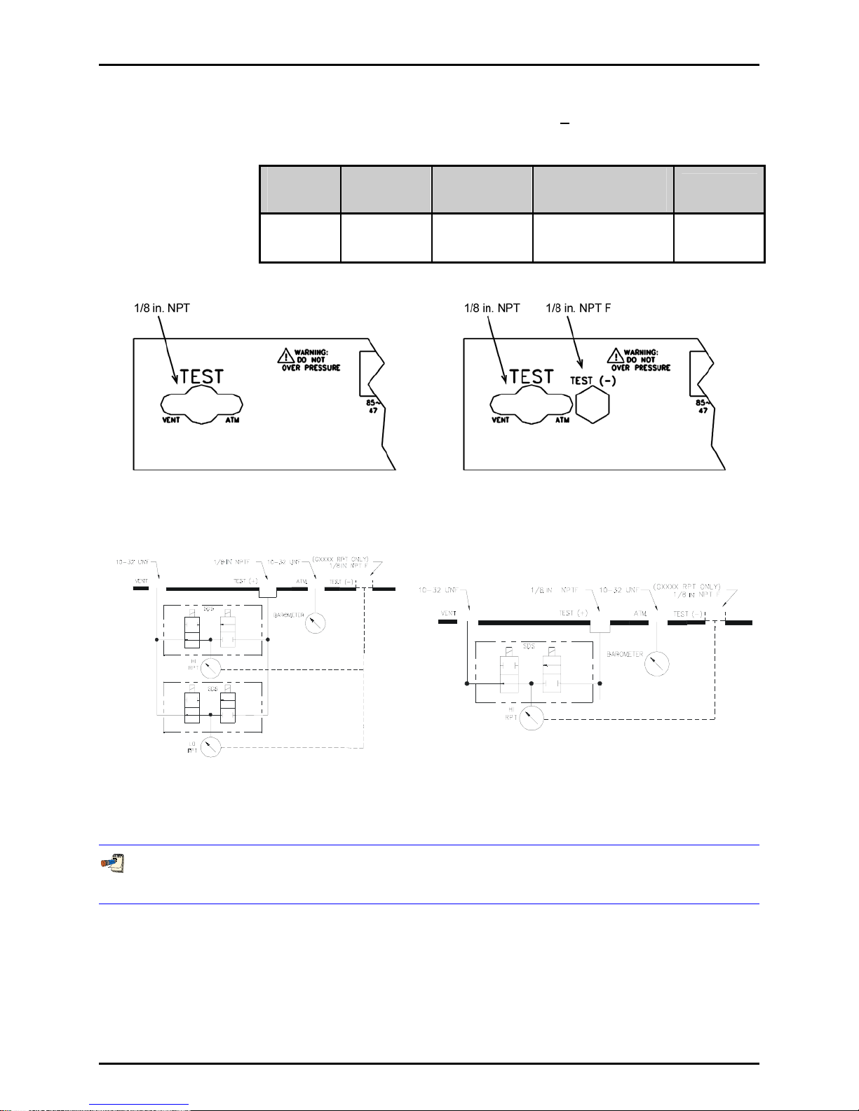
Figure 1 Rear Panel
(Left) One or Two Group 1 RPTs
(Right) One or Two Group 1 RPTs with a GXXXX RPT
Group 1 liquid filled RPTs do NOT have SDS and MUST have their own test port. Therefore, liquid filled
Group 1 RPTs are presented in Group 2 format. See Sections 1.2.3.2, 1.2.3.3 and 1.2.3.4.
© 1998-2002 DH Instruments, Inc. Page 6
Figure 2 Schematic
(Left) Two Group 1 RPTs
(Right) One Group 1 RPT

1. INTRODUCTION
1.2.3.2 TWO RPTS: ONE GROUP 1 (> A1500) AND ONE GROUP 2
(> A1500 AND < A10000) OR ONE LIQUID FILLED GROUP 1
Table 5 Two RPTs: One Group 1 (> A1500) and One Group 2
(> A1500 and <
A10000) or One Liquid Filled Group 1 Specifications
NUMBER
OF TEST
PORTS
2 1/8 in. NPT F 1/8 in. NPT F 1/8 in. NPT F
HI RPT
TEST PORT
FITTING
LO RPT TEST
PORT FITTING
(IF 2 RPTS)
TEST (-) PORT
FITTING
(IF GXXXX RPT PRESENT)
SDS
PROTECTION
YES
(On LO, Group
1 RPTs only)
Figure 3 Rear Panel
(Left) One Group 1 RPT and One Group 2 RPT
(Right) One Group 1 GXXXX RPT and One Group 2 RPT
Page 7 © 1998-2002 DH Instruments, Inc.
Figure 4 Schematic
One Group 1 RPT and One Group 2 RPT

RPM3™ OPERATION AND MAINTENANCE MANUAL
1.2.3.3 TWO RPTS: BOTH GROUP 2 (> A1500 AND < A10000) OR
LIQUID FILLED GROUP 1
Table 6 Two RPTs: Both Group 2 (> A1500 and < A10000) or
Liquid Filled Group 1 Specifications
NUMBER
OF TEST
PORTS
2 1/8 in. NPT F 1/8 in. NPT F
HI RPT
TEST PORT
FITTING
LO RPT TEST
PORT FITTING
(IF 2 RPTS)
SDS
PROTECTION
YES
(On LO, Group
1 RPTs only)
Figure 5 Two Group 2 RPTs
(Left) Rear Panel / (Right) Schematic
© 1998-2002 DH Instruments, Inc. Page 8

1. INTRODUCTION
1.2.3.4 ONE RPT: GROUP 2 (> A1500 AND > A10000) OR GROUP 3
(> A10000) OR LIQUID FILLED GROUP 1
Table 7 One RPT: Group 2 (> A1500 and < A10000) or
Group 3 (> A10000) or Liquid Filled Group 1 Specifications
NUMBER
OF TEST
PORTS
1
1/8 in. NPT F (If Group 2)
HI RPT
TEST PORT FITTING
DH500 F (If Group 3)
SDS
PROTECTION
NO
Figure 6 Rear Panel
(Left) One Group 2 RPT
(Right) One Group 3 RPT
Page 9 © 1998-2002 DH Instruments, Inc.
Figure 7 Schematic
(Left) One Group 2 RPT
(Right) One Group 3 RPT

RPM3™ OPERATION AND MAINTENANCE MANUAL
N
N
OOTTEES
S
© 1998-2002 DH Instruments, Inc. Page 10

2. INSTALLATION
22..
I
NNSSTTAALLLLAATTIIOON
I
N
2.1 UNPACKING AND INSPECTION
2.1.1 REMOVING FROM PACKAGING
RPM3 is delivered, along with its standard accessories, in a custom corrugated container
with polyurethane inserts to hold it in place.
Remove the RPM3 and its accessories from the shipping container and remove each
element from its protective plastic bag.
2.1.2 INSPECTING CONTENTS
Check that all items are present and have NO visible damage.
A standard RPM3 includes all items listed in Table 8.
Table 8 RPM3 Parts List
DESCRIPTION PART #
1 ea. RPM3 Reference Pressure Monitor FAM0003
1 ea. Calibration Certificate 550100
1 ea. Wrench, Open End, 5/8 in. 103044
1 ea. General Accessories Disk (white CD) 102987
ACCESSORIES: 401455
1 ea. User’s Manual 550094
1 ea. Power Cord (7.5 ft.) 100770
1 ea. General Accessories Disk (Important: Includes
system support software and documentation.)
102987
2.2 SITE REQUIREMENTS
Install RPM3 on any stable surface at a convenient height. The front feet are extendible so that the unit
can be inclined for easier viewing.
The RPM3 can also be mounted in a standard 19 in. rack mount using the optional rack mount kit.
Consider ready access to the RPM3 rear panel if TEST port connections may be changed frequently.
Support facilities required include an electrical power source of 85 to 264 VAC, 47 to 440 Hz.
Page 11 © 1998-2002 DH Instruments, Inc.

RPM3™ OPERATION AND MAINTENANCE MANUAL
2.3 INITIAL SETUP
2.3.1 PREPARING FOR OPERATION
To prepare RPM3 for check out and operation:
Remove the plastic caps from the RPM3 rear panel pressure connections.
Remove the protective plastic sheet from the front panel display.
Familiarize yourself briefly with the front and rear panels (see Sections 2.3.2.1 and
2.3.2.2).
2.3.2 FRONT AND REAR PANELS
2.3.2.1 FRONT PANEL
The front panel assembly provides a 2 X 20 vacuum fluorescent display of RPM3
operating status, a membrane keypad for local user interface and a soft ON/OFF key.
1
2
1. Display
2. Multi-Function Keypad
3. Remote Indicator
5
4
Figure 8. Front Panel
3
4. RPT Designator Label
5. Soft ON/OFF Key and Indicator
© 1998-2002 DH Instruments, Inc. Page 12

2. INSTALLATION
2.3.2.2 REAR PANEL
The rear panel assembly provides pressure connections, communications
interfaces and the power connection module. Pressure fittings are internally
secured to prevent loosening when making and breaking connections.
2
3
1. Pressure Port(s), layout depending on RPT
Configuration (see Section 1.2.3)
2. Electrical Power Connector Configurations
(IEC320-C13)
Figure 9. Test Ports
3. IEEE-488 (GPIB) Connector
4. COM1 Connector
5. COM2 Connector
6. Label, Product (on bottom of case)
4
2.3.3 POWER CONNECTION
• Connect the power cable to the rear panel power module
• Do NOT connect the other end of the power cable to a power source yet
RPM3 is always powered and active when power is supplied through the rear panel power
connector. The front panel ON/OFF key controls a soft ON/OFF (see Section 3.1.2.3).
2.3.4 TEST PORT CONNECTING
Depending on the reference pressure transducer (RPT) configuration of the specific RPM3,
the TEST port layout, TEST port fittings and acceptable test medium differ (see Sections
1.2.3 and 1.2.1).
Using a pressure hose or tube of appropriate pressure rating, connect the appropriate TEST
port to the test system or supply from which pressure is to be measured. The RPM3 TEST
port is either a 1/8 in. NPT F or a DH500 F, high pressure fitting. Always use compatible
male hardware of the same type. Use Teflon tape or another sealer to make 1/8 in. NPT
connections.
If RPM3 is equipped with a gauge RPT (GXXXX), it has a TEST(-) port. The TEST(-) port is
connected to the low side of the gauge RPT. This connection is normally left open to
atmosphere. It can also be connected to the low side of a differential device that is being
calibrated or tested. When measuring very low pressures, this may enhance the results by
helping assure that the RPM3 and the device under test reference ports are at the same
pressure (see Section 1.2.3).
Page 13 © 1998-2002 DH Instruments, Inc.

RPM3™ OPERATION AND MAINTENANCE MANUAL
USE THE CORRECT TEST PORT: Some RPM3s have more than one TEST port
corresponding to more than one internal RPT. Before connecting an RPM3 TEST port to a
pressure source, familiarize yourself with the RPTs, their pressure limits and their TEST
port fittings (see Section 1.2.3). In most cases, over-pressuring an RPT by more than
25 % will damage it beyond repair.
USE THE CORRECT PRESSURE CONNECTORS: RPM3 TEST port fittings are either 1/8 in.
NPT F or DH500 F (see Section 1.2.1). Never use fittings other than the corresponding
male fittings in these connectors. Damage to the connectors and dangerous failure
under pressure could result from using incorrect fittings.
NEVER connect a pressure source to the TEST(-) port. The pressure applied to this port
should be maintained at standard atmospheric pressure ± 3 psi (20 kPa). Exceeding
these limits may damage the RPT.
USE THE PROPER MEDIUM: b Type RPTs are intended for use only with dry (instrument
grade, non-condensing), non-corrosive gases. Contaminated gases may cause
measurement shifts and offsets. Standard RPTs are delivered for set up for gas
operation (A6000 and lower) or liquid operation (A10000 and higher). Contaminating
gas operated RPTs with liquids may cause aberrant measurements.
SDS Self Defense System: RPTs designated A1500 or lower include the SDS Self Defense
System. SDS, operated properly, allows a Group 1 RPT TEST port (see Section 1.2.3) to
be left connected to a pressure up to 2 000 psi (13 MPa) without damage to the RPT.
Do NOT attempt to use SDS in this manner without first becoming thoroughly familiar
with its operations and limitations (see Sections 3.1.2.6, 3.2.8, and 3.4.2).
2.3.4.1 THE ATM AND VENT PORTS
The ATM pass through is connected to the on-board barometer. This connection
assures that the on-board barometer actually measures ambient atmospheric
pressure rather than the pressure inside the RPM3 case that may vary slightly
from ambient pressure. The ATM port should be left open and unobstructed.
The VENT port is only present on RPM3s equipped with SDS Self Defense
System (Group 1 RPTs only) (see Sections 1.2.3 and 3.1.2.6). The VENT port is
connected to the SDS vent valve to assure that any gases vented through SDS
escape outside the RPM3 case. A connection may be made to the VENT port to
direct these gases if desired but the port must NOT be obstructed. Obstructing
the VENT port may interfere with SDS operation.
NEVER plug or obstruct the ATM pass through as this may adversely affect
gauge mode operation and autozeroing on an absolute transducer.
© 1998-2002 DH Instruments, Inc. Page 14

2. INSTALLATION
NEVER plug or obstruct the VENT pass through as this may interfere with
SDS operation and RPT autozeroing (see Section 3.1.2.6).
2.4 POWER UP AND VERIFICATION
2.4.1 APPLY POWER
Connect the RPM3 power cable to an electric supply of 85 to 264 VAC (47 to 440 Hz).
Observe the front panel display as RPM3 initializes, error checks and goes to the main run
screen (see Section 3.1.1).
RPM3 is always powered and active when power is supplied through the rear panel power
connector. The front panel ON/OFF key controls a soft ON/OFF (see Section 3.1.2.3).
If the RPM3 fails to reach the main run screen, service is required. Record the sequence of
operation and displays observed.
Any SDS present in RPM3 is active at power up. This causes SDS to flash over the
measured pressure (see Section 3.1.2.6).
The active range on power up is the same as the range that was active at the last power
down (see Section 3.1.2.5).
2.4.2 CHECK PROPER PRESSURE MEASUREMENT
OPERATION
2.4.2.1 CHECKING ABSOLUTE MODE PRESSURE MEASUREMENT
If the RPM3 has an absolute RPT (designated AXXXX), check that it operates properly in
absolute mode.
Make sure that the TEST port of the RPT is open to atmosphere.
Use [RANGE] to change ranges if necessary (see Section 3.2.1). Select a range of the
absolute RPT.
Press [MODE] and select absolute mode (available on AXXXX RPTs only). Change the
pressure unit if desired (see Section 3.2.2).
If SDS is ON (SDS flashes over the pressure indication on the top display line), turn SDS
OFF. Press [SDS] and select <2 Yes> to defeat SDS (see Section 3.2).
Do NOT defeat SDS with a pressure higher than the active range maximum applied to the
TEST port. Damage to the RPT may result.
Page 15 © 1998-2002 DH Instruments, Inc.

RPM3™ OPERATION AND MAINTENANCE MANUAL
Observe the current value of atmospheric pressure. Check that the value agrees with the
local value of atmospheric pressure within measurement tolerances. Repeat this process for
all the ranges on both RPTs if the RPM3 has two absolute RPTs. Check that the values of
atmospheric pressure measured by the different ranges agree with each other within RPM3
measurement tolerances (see Section 1.2.2). If they do NOT agree within tolerances, RPM3
may need calibration or repair.
2.4.2.2 CHECKING GAUGE MODE PRESSURE MEASUREMENT
Make sure that the TEST port(s) of the RPT(s) is/are open to atmosphere.
Use [RANGE] to change ranges if necessary (see Section 3.2.1). Select a range
of the RPT.
Press [MODE] and select gauge mode. Change the pressure unit if desired
(see Section 3.2.2).
If SDS is ON (SDS flashes over the pressure indication on the top display line),
turn SDS OFF. Press [SDS] and select <2Yes> to defeat SDS (see Section
3.2.8).
Do NOT defeat SDS with a pressure higher than the RPT maximum applied to
the TEST port. Damage to the RPT may result.
The value indicated should be near zero (± 6 psi, 35 kPa). Press [AutoZ]. This
runs AutoZ to zero the range (see Section 3.2.9). Upon return to the main run
screen, observe that the indication of measured pressure has zeroed.
Use [RANGE] to change ranges, repeat the zeroing process for each range.
If a range fails to zero properly, RPM3 may need repair.
It is normal for RPM3 to indicate a value other than zero when vented when
gauge mode is first entered or ranges are changed, especially if AutoZ is OFF
and/or RPM3 has been OFF for some time or its location has changed.
2.5 SHORT TERM STORAGE
The following is recommended for short term storage of RPM3:
Vent the RPM3 TEST port.
Disconnect the power supply.
When RPM3 will NOT be used for some time, it may be left powered, but use the soft ON/OFF key to turn
OFF the display.
© 1998-2002 DH Instruments, Inc. Page 16

3. OPERATION
33..
O
PPEERRAATTIIOON
O
N
3.1 GENERAL/MANUAL OPERATION
RPM3 is designed to offer the optimum balance between simple, straight forward operation and the
availability of a wide variety of functions with a high level of operator discretion if desired. The local
operator interface is through a 2 x 20 character alpha-numeric display and a 4 x 4 multi-function keypad.
3.1.1 MAIN RUN SCREEN
The RPM3 main run screen is its home display that is reached on power up and from which
other functions and menus are accessed. It is the top level of all menu structures.
The main run screen is where the RPM3 is left in normal operation. It displays the current
measured pressure as well as a variety of additional information if desired.
1. <k> Ready/NOT ready indication, <k> when ready, <-> or
<¯> indicating direction of measured pressure evolution when
NOT ready (see Section 3.1.2).
2. <PRESSURE1> Numerical value and sign of pressure
measured by active RPT and range. Shows result of last
average in average display mode (see Section 3.2.6.1).
<**SDS**>: To indicate when SDS is ON (see Section
3.1.2.6) for the active RPT, **SDS** is displayed alternating
with PRESSURE1.
3. <UNIT> Current unit of measure (see Section 3.2.2).
4. <M> Pressure measurement mode: <g> for gauge, <a> for absolute (see Sections 3.2.3 and 3.2.2).
5. <h> Indicates whether a head correction is applied. <h> if applied, blank if NOT (see Section 3.2.7).
6. <z> Indicates whether the autozero function is ON or OFF. <z> if ON; blank if OFF (see Section 3.4.1).
7. <RR> Indicates active RPT (<H> = high, <L> = low) and range (<1> = low, <2> = mid, <3> = hi) (see Section 3.2.1).
8. <DISPLAY FUNCTION> Information displayed depends on current display function.
9. <D> Indication of what is being displayed on the bottom line of the display as set by the DISPLAY function
(see Section 3.2.6). Choices include:
• <s> Current DISPLAY mode is average (see Section 3.2.6.1).
• <R> Current DISPLAY mode is rate (see Section 3.2.6.2); or if <n avg> is in the bottom right hand corner
of the display, current DISPLAY mode is average and this is the instantaneous reading average screen
(see Section 3.2.6.1).
• <H> Current DISPLAY mode is hi/lo (see Section 3.2.6.5).
• <D> Current DISPLAY mode is deviation (see Section 3.2.6.3).
• <S> <-> or <¯> Current DISPLAY mode is RPT (see Section 3.2.6.4).
• <F> Current DISPLAY mode is freeze (see Section 3.2.6.6).
• Blank, NO character Current DISPLAY mode is clean (see Section 3.2.6.7).
* PRESSURE1 UNITM hZRR
D DISPLAY FUNCTION
RPM3 has a screen saver function that causes the display to dim if NO key is pressed
for 10 minutes. Pressing a key restores full power to the display. The screen saver
activation time can be changed or screen saving can be completely suppressed (see
Section 3.4.7.1).
Page 17 © 1998-2002 DH Instruments, Inc.
RPM3™ OPERATION AND MAINTENANCE MANUAL
3.1.2 GENERAL OPERATING PRINCIPLES
3.1.2.1 KEYPAD LAYOUT AND PROTOCOL
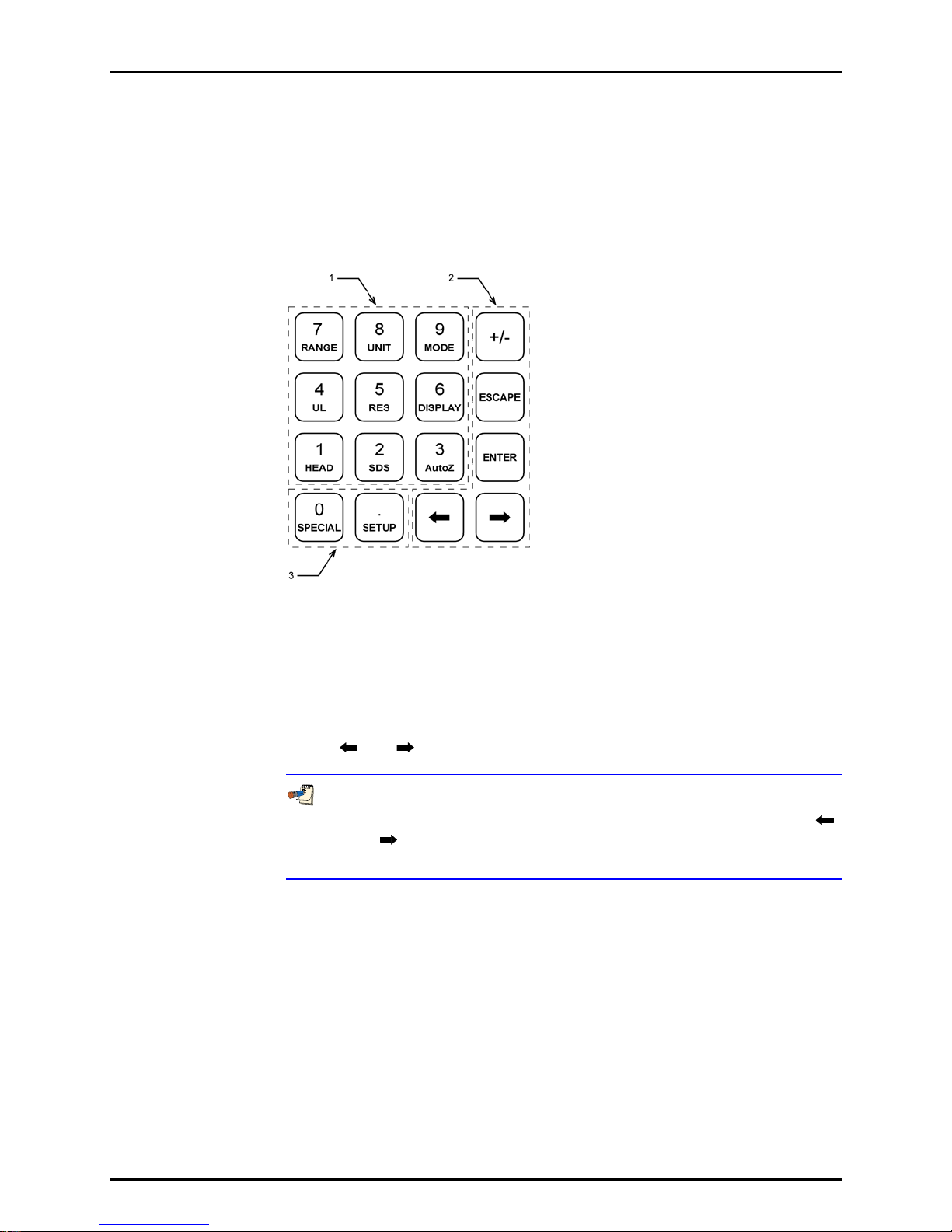
The RPM3 has a 4 x 4 keypad for local operator access to direct functions,
function menus and for data entry.
The [ENTER] key generally causes execution or forward movement in the menu tree.
The [ESCAPE] key moves back in the menu tree and/or causes execution to cease or suspend
without changes being implemented. Pressing [ESCAPE] repeatedly eventually returns to the
main run screen. From the main run screen, pressing [ESCAPE] allows momentary viewing of
the RPM3 introduction screen.
The [+/-] key changes a numerical sign when editing. It also toggles through multiple screens
when available.
The [
They are also used to scroll through choices.
] and [ ]keys allow reverse and forward cursor movement when editing data entry.
Figure 10 Keypad
1. The Function/Data keys allow very commonly
used functions to be accessed directly from the
main run screen by a single keystroke. The
name of the function is on the bottom half of the
key (see Section 3.1.2.7). These keys enter
numerical values when editing.
2. The Editing and Execution keys are for
execution, suspending execution, backing up in
menus and editing entries.
3. The Menu/Data keys provide access to function
menus from the main run screen. The menu
name is on the bottom half of the key. The
SETUP menu is for more frequently used
functions (see Section 3.3). The SPECIAL menu
is for functions that are NOT generally used as a
part of day to day operation (see Section 3.4).
These keys enter numerical values when editing.
Key press confirmation is provided by both tactile
and audible feedback. A single tone confirms a
valid entry, a descending two note tone signals
an invalid entry. The audible valid entry feedback
can be suppressed or modified by pressing
[SPECIAL] and selecting <7Intern>, <2sound>
(see Section 3.4.7.2).
Some screens go beyond the two lines provided by the display. This is
3.1.2.2 SOUNDS
RPM3 is equipped with a variable frequency tone device to provide audible
feedback and alarms. The beeper is used for the following indications.
Valid key press - Brief beep, choice between three frequencies or NO sound is
available (see Section 3.4.7.2)
Invalid key press - Descending two tone blurp
Leak check routine completed - Three two second beeps (see Section 3.3.5)
UL (upper limit) exceeded - Intermittent one second beeps (see Section 3.2.4)
Pmax! (overpressure limit) exceeded - Eight second high frequency beep
(see Section 3.2.4.1)
© 1998-2002 DH Instruments, Inc. Page 18
indicated by a flashing arrow in the second line of the display. Use [ ]
and [
] to move the cursor to access the lines that are NOT visible or
directly enter the number of the hidden menu choice if you know it.

3. OPERATION
3.1.2.3 SOFT [ON/OFF] KEY
RPM3 is equipped with a soft [ON/OFF] key and indicator LED on the bottom left
hand corner of the front panel. The purpose of the soft ON/OFF key is to put
RPM3 into a dormant mode in which the display is turned OFF but power is still
supplied and SDS and overpressure functions are still active. When RPM3 is
ON, the ON/OFF indicator is ON continuously. When RPM3 is soft OFF, the
ON/OFF indicator blinks every five seconds.
The soft [ON/OFF] key can also be used to reset from an overpressure condition
(see Section 3.2.4.1).
When RPM3 is soft OFF, receiving a remote command turns it ON.
Turning RPM3 soft OFF does NOT turn SDS ON. Do NOT assume that SDS
is ON when an RPM3 is soft OFF. Disconnecting power completely turns
SDS ON (see Section 3.1.2.6).
3.1.2.4 PRESSURE READY <*>/NOT READY (<↑> OR <↓>)
The character to the left of the measured pressure on the main run screen
provides a pressure Ready (<*>)/Not Ready (<↑> or <↓>) indication.
This indication is intended to provide the user with a clear and objective
indication of when a stable pressure has been achieved. Ready <*> is indicated
when the current stability (rate of change) of pressure is less than the stability
limit.
The user can set the stability limit (see Section 3.3.4). The ready indication is
often used when comparing the RPM3 and a test device to indicate when a valid
reading can be made.
Ready (<*>)/Not Ready (<↑> or <↓>) character indications are:
<k > Pressure ready (stable)
<↑> Pressure NOT ready (unstable) and decreasing
<↓> Pressure NOT ready (unstable) and increasing
3.1.2.5 MULTIPLE PRESSURE RANGES
RPM3 has one or two reference pressure transducers (RPT) each of which has
three ranges for a total of three or six pressure ranges. This multi-ranging
feature allows accuracy to be optimized for the range of pressure in which you
are working. Generally, the best range to select (see Section 3.2.1) is that
whose full scale is closest to, but greater than, the maximum pressure of the
device or system under test.
RPM3 handles all of the data operations needed to make range changes occur
transparently to the user when the RANGE function is used for range selection.
For a range change to be executed, the current pressure applied to the RPT on
which the range is being selected must be lower than the current upper limit (UL)
of that range (see Section 3.2.4).
When ranges are changed, the upper limit is automatically changed to the default
for that range or to the last upper limit set for that range. In addition, most other
functions and settings are range specific (see Section 3.2.1).
Page 19 © 1998-2002 DH Instruments, Inc.

RPM3™ OPERATION AND MAINTENANCE MANUAL
Each RPM3 has three or six ranges. In general, settings and operational
adjustments are specific to the range currently in use, as if you had six
instruments rather than one. The DISPLAY function, HEAD functions and
AUTO READRT function are NOT range specific. In remote mode, most
settings are RPT specific rather than
RPM3 internal pressure schematics and rear panel TEST port configurations
change depending on the number of RPTs and their ranges. See Section 1.2.3
for details on possible RPM3 configurations.
Ranges and Identification
The currently active RPT and range is continuously indicated in the upper right
hand corner of the main run screen and most other screens (see Section 1.2.2
for complete listing of the RPTs available and their ranges).
Hi RPT The RPT in a single RPT RPM3 or the RPT with the highest
maximum range in a dual RPT RPM3 is referred to as the Hi RPT.
Lo RPT The RPT with the lower maximum range in a dual RPT RPM3
is referred to as the Lo RPT.
Range 1, 2 or 3 The three ranges of an RPT are referred to as 1 = lo range,
2 = mid range, 3 = hi range.
Table 9. RPM3 Range Identification Summary
REFERENCE PRESSURE
TRANSDUCER AND RANGE
Lo RPT, Lo range Lo, 1 L1
Lo RPT, Mid range Lo, 2 L2
Lo RPT, Hi range Lo, 3 L3
Hi RPT, Lo range Hi, 1 H1
Hi RPT, Mid range Hi, 2 H2
Hi RPT, Hi range Hi, 3 H3
* The display symbol is included in the upper, right hand corner of most RPM3 menu displays as a convenient
indicator of active range.
DESIGNATION DISPLAY SYMBOL *
3.1.2.6 SDS SELF DEFENSE SYSTEM
RPTs designated A1500 or lower that are NOT liquid filled are equipped with the
SDS self defense system. The SDS system includes hardware and embedded
software logic to protect RPTs from overpressure. When SDS is ON for an RPT,
that RPT is isolated from the RPM3 TEST port and opened to the VENT port
(See Figure 11 and Sections 1.2.3 and 5.6.1.1).
In dual RPTs with a single TEST port, SDS is used to protect the Lo RPT from
overpressure when the high RPT is in use.
RPM3 internal logic uses SDS to protect against accidental overpressure.
Whenever RPM3 is ON (or in soft OFF mode) it monitors the pressure read by its
RPTs. If the pressure reaches the maximum pressure limit for a range, SDS will
activate automatically to isolate the RPT from the TEST port and vent it to
atmosphere.
© 1998-2002 DH Instruments, Inc. Page 20

3. OPERATION
SDS can also be used to isolate an RPM3 from a test system which may
sometimes be subjected to pressures higher than the RPM3s maximum
pressure. When configuring a multi-range system, this can eliminate the need
for external valving or connecting and disconnecting RPM3s. When used in this
manner, SDS should be activated prior to applying pressure. Automatic SDS
activation should only be used in an emergency overpressure situation.
SDS ON - ISOLATION Closed / VENT Open
SDS OFF - (Defeated) ISOLATION Open / VENT Closed
Figure 11 SDS Schematic
The maximum pressure that should be applied to an RPM3 TEST port when
SDS is ON is 2 000 psi (13 MPa).
Though the SDS self defense system includes features to automatically
protect RPTs against accidental overpressure, SDS should NOT be
considered a fail-safe overpressure protection system. SDS cannot
guarantee that overpressure damage will NOT occur. SDS automatic
activation may protect an RPT in case of accidental overpressure but
conventional measures for protecting against overpressure should also
always be followed. Damage to RPTs due to overpressure is NOT covered by
the RPM3 product warranty even when SDS is present.
3.1.2.7 DIRECT FUNCTION KEYS SUMMARY
Local operation of RPM3 is through the 4 x 4 pressure sensitive keypad. To
minimize the use of multi-layered menu structure, the 4 x 4 keypad numerical
keys also provide direct access to the most commonly used functions. The
function accessed is labeled on the bottom half of the keys. Direct function keys
are active whenever RPM3 is in its main run screen. Table 10 summarizes the
operation of the direct function keys.
Table 10 provides a brief summary of direct function key operation. It may be
Page 21 © 1998-2002 DH Instruments, Inc.
useful to keep a copy of this summary near the RPM3, especially when first
becoming acquainted with its operation.

RPM3™ OPERATION AND MAINTENANCE MANUAL
Table 10 Summary of RPM3 Direct Function Key Operation
Direct function keys are active from the main run screen.
See corresponding manual sections for full detail.
DIRECT FUNCTION KEYS ARE ACTIVE FROM ANY RUN SCREEN
See corresponding manual sections for full detail.
Menu of commonly used setup
features including run LEAK
CHECK.
(main, ambient, system).
View/adjust upper limit.
Menu of commonly used setup
features including run LEAK
CHECK.
Menu of less frequently used
internal functions and settings.
Adjust height of fluid head
correction. Set to zero to defeat
head correction.
Turn SDS (Self Defense System)
ON/OFF (if present). SDS ON is
indicated by flashing <***SDS***>.
SDS must be turned OFF to
measure pressures applied to
TEST port. Use with caution as
turning SDS OFF with
overpressure on test port could
damage RPT.
Runs AutoZ to rezero active
range. Should be used in gauge
mode whenever vented.
3.2 DIRECT FUNCTION KEYS
Adjust display resolution of
measured pressure and other
indications and settings.
Select [DISPLAY] function for
second line of RPM3 display.
Choices include <average>,
<rate>, <other RPT>, <Hi/Lo>,
<Deviation>, <Freeze>, <Clean>.
View/Select ranges. Shows active
range and then toggles through
available ranges. Pressing
[ENTER] on a range activates it.
Change pressure measurement
unit. Choice of units can be
customized.
Change pressure measurement
mode (<gauge>, <absolute>).
3.2.1 [RANGE]
PURPOSE
To view and/or change the active pressure measurement range.
PRINCIPLE
Each RPM3 has three or six ranges (see Section 3.1.2.5).
The [RANGE] key allows the range values to be viewed and a range selection to be made.
Most RPM3 settings such as pressure unit of measure (UNIT) and measurement mode
(MODE), are range specific. Changes made while in one range apply to that range only and
do NOT affect the other ranges (see Section 3.2.1).
OPERATION
Pressing [RANGE] activates the range viewing and selecting function. Pressing [RANGE]
key again or [+/-] while in the RANGE function steps through displays of available ranges:
Lo to Hi.
© 1998-2002 DH Instruments, Inc. Page 22

3. OPERATION
When [RANGE] is first pressed, the active reference pressure transducer (RPT) and range
are displayed, for example:
1. Identifies active RPT (LO or HI).
2. Identifies active range (1, 2 or 3) of the active RPT.
3. Range designator.
4. Full scale pressure value in the current units for the RPT and
range when used in gauge (g) or absolute (a) mode. If the
RPT is a gauge only RPT there is NO absolute (a) range
indicated.
5. Unit of measure (the unit of measure currently active for this
range).
Current LO,Rng3 L3
psi 35g/50a
Pressing [RANGE] again or [+/-] causes the screen to step through the other available
ranges in sequence Lo to Hi, for example:
1. Identifies RPT (LO or HI).
2. Identifies range of the RPT (1, 2 or 3).
3. Range designator.
4. Full scale pressure value in the active units of measure for
the RPT and range number when used in gauge (g) or
absolute (a) mode. If the RPT is a gauge only RPT there is
NO absolute (a) range indicated.
5. Units of measure (the unit of measure currently active for the
range).
Select HI,Rng1 H1
psi 300g/300a
Range full scale limits are given in the pressure unit that is currently active for that
range.
Pressing [ENTER] while in the RANGE function causes the RPM3 to attempt to change the
active range to the range currently displayed. If the pressure currently applied to the RPT
with the new range is less then the current upper limit of that range (see Section 3.2.4), the
range change will be completed.
Pressing [ESCAPE] while in the range function returns to the main run screen without
changing ranges.
For a range change to occur, the pressure currently measured by the new range RPT must
be less than the current upper limit (see Section 3.2.4) of the new range. If this
condition is NOT met when a range change is attempted, a warning message is displayed
and the range change is NOT completed. Reduce the pressure applied to the TEST port
and reattempt the range change. It is, however, possible to make a range change from
RPT to another with pressure applied to the current RPT. If both RPTs are on a common
TEST port, be sure to reduce pressure on the TEST port before making the range change.
SDS and Range Changes
Changing ranges causes the active RPT to change from the Lo RPT to the Hi RPT or viceversa, SDS will be turned ON for the RPT that is being changed from. This leaves the
inactive RPT with SDS ON so that it is protected.
When changing ranges causes the active RPT to be changed, if the new active RPT is
equipped with SDS, SDS will almost certainly be ON when the new range is activated (as
indicated by the flashing SDS alternating with the pressure display). To open the RPT to the
TEST port SDS must be turned OFF using the SDS function key (see Section 3.2.8).
Page 23 © 1998-2002 DH Instruments, Inc.

RPM3™ OPERATION AND MAINTENANCE MANUAL
4
4
Range Specific Functions and Settings
In general, RPM3 functions and settings are range specific. They are set and stored for each
range so that changing settings when in one range does NOT change settings in the other
ranges. When returning to a range, settings are be the same as they were when the range
was left.
Functions and settings that are NOT range specific are:
• Functions HEAD (see Section 3.2.7), DISPLAY (see Section 3.2.6)
• Setup Menu <3ReadRt> (see Section 3.3.3)
In remote mode, most settings are RPT specific rather than range specific (see Section 4.3).
3.2.2 [UNIT]
PURPOSE
To specify the pressure unit of measure for the active range.
See also Section 3.2.3.
PRINCIPLE
RPM3 allows the pressure measurement unit for a range to be changed. Internally, RPM3
always operates in Pascal (Pa), the SI unit of pressure. Values of pressure are represented
in other units by the application of conversion factors to convert from Pa (see Section 7.1).
The pressure measurement unit selection (e.g., psi, kPa, etc.) is separate from the pressure
measurement mode selection (gauge or absolute). See Section 3.2.3 for information on
changing the measurement mode.
OPERATION
To change the pressure measurement unit for the active range, press the [UNIT] function
key. The display is:
The cursor is on the number corresponding to the
active unit for the active range. To change the
pressure unit for the active range, select the desired
unit. The display returns to the main run screen with
1psi 2inWa 3inHg H3
kPa 5mmHg 6kcm2
the selected unit active.
If the pressure unit selected is inWa the reference
temperature for water density must be specified.
When inWa is selected as the unit, the next display is:
Select inWa ref temp
°C 20°C 60°F
Select the desired reference temperature for water density using [↑] or [↓] key to move the
cursor. Pressing [ENTER] returns to the main run screen with inWa based on water density
at the selected reference temperature as the pressure unit. The current inWa reference
temperature can be viewed by observing the position of the cursor in the reference
temperature screen. Reference temperature for inch of water units is NOT range specific.
No reference temperature selection is necessary for the unit mmWa as the only reference
temperature commonly used for mmWa is 4 ºC.
© 1998-2002 DH Instruments, Inc. Page 24

3. OPERATION
1
The pressure measurement unit selected is range specific. When in a given range, all
functions and settings are represented in the current measurement unit for that range.
However, certain internal and/or metrological functions (e.g., RPT calibration coefficients)
are always represented in Pa regardless of the active range unit. In addition, when the
current unit is an altitude unit, the range and upper limit indications are in kPa if the unit
is meters (m) and in psi if the unit is feet (ft).
See Section 7.1 for tables of the conversion factors used by RPM3.
The UNIT function provides rapid access to a choice of six units. The choice of units can
be customized from a wider selection by the user (see Section 3.3.2). The default six
units of the UNIT function depend on whether the RPM3 is set up as a US or SI version
(indicated by US or SI in the bottom right hand of the RPM3 introduction screen).
To return the six units of the UNIT function key to default, see Section 3.4.5.2.
3.2.3 [MODE]
PURPOSE
To set the measurement mode (gauge or absolute) for the active range.
See Section 3.2.2 also.
OPERATION
RPTs designated AXXXX can be used by RPM3 to measure absolute or positive and
negative gauge pressure. AXXXX RPTs have an evacuated and sealed reference so that
they always measure absolute pressure. RPM3 supports extensive on-board measurements
and logic to precisely subtract atmospheric pressure from absolute pressure when gauge pressure
measurements are desired. A separate on-board barometer and unique atmospheric
compensation system are used to assure highly accurate gauge pressure values even if
atmospheric pressure changes between zeroing opportunities (see Section 3.4.1). This
allows simple, one step switching between gauge and absolute measurement modes without
special procedures or hardware.
RPTs designated GXXXX are referenced to atmospheric pressure. GXXXX RPTs are only
used to measure gauge pressures. They do NOT support absolute measurement mode.
To change the pressure measurement mode for the
active range, press [MODE]. The display is:
Measurement mode: H1
absolute 2gauge
The cursor is on the number corresponding to the current measurement mode. Making a
measurement mode selection returns to the main run screen with the selected mode active.
If a measurement mode change is NOT currently possible (if the active RPT is gauge only
or if the current pressure unit is an altitude unit which can only be absolute), an error
message displays when [MODE] is pressed.
Page 25 © 1998-2002 DH Instruments, Inc.

RPM3™ OPERATION AND MAINTENANCE MANUAL
When going from absolute to gauge measurement mode, the AutoZ function should be
used to update the atmospheric pressure offset (see Sections 3.2.9, 3.2.9, and 3.4.1).
3.2.4 [UL] (UPPER LIMIT)
PURPOSE
To set the upper limit value for the active range and measurement mode.
PRINCIPLE
The UPPER LIMIT function provides the user with a settable pressure limit at which an alarm
will sound.
When the upper limit is reached the RPM3’s beeper sounds intermittently.
The UPPER LIMIT function has two purposes. First, when UL is set to its default value, it
serves as a warning that the maximum pressure of the active range is about to be exceeded.
Second, UL can be set by the user to a lower value than the default value to provide an alarm
that a specific pressure limit has been exceeded. This feature is often used to help protect
an external device or system on which RPM3 is being used to measure pressure. For
example, it might be set just over the full scale of a device under test (DUT) that is being
calibrated.
The UL function is separate and different from the over-pressure (Pmax!) function. The Pmax!
function is NOT adjustable and activates regardless of UL setting when the maximum
acceptable pressure for the active RPT range has been exceeded (see Section 3.2.4.1).
Upper limit settings are specific to each range and measurement mode (gauge or absolute).
OPERATION
When [UL] is pressed from the main run screen the display is:
Upper limit: H3
1. Edit field to view current upper limit value and modify if
desired.
105 psi a
Enter the desired upper limit value and RPM3 returns to the main run screen with the new
upper limit value active.
When the upper limit has been exceeded, the display of current pressure flashes and the
beeper sounds three times for two seconds. Reduce the pressure applied to the RPT to less
than the upper limit to return to normal operation. For RPTs equipped with SDS, the SDS
function can be used to isolate the RPT from the TEST port and rapidly vent it to atmosphere
(see Sections 3.1.2.6 and 3.2.8).
Default upper limit values are 105 % of the range full scale for ranges 1 and 2 and 102 % FS for
range 3. If the range full scale is less than or equal to atmospheric pressure the default UL is
just over atmospheric pressure to avoid exceeding UL when open to atmosphere. Upper limit
values may be adjusted by the user. The adjusted value must be lower than or equal to the
default value and lower then the current measured pressure.
© 1998-2002 DH Instruments, Inc. Page 26

3. OPERATION
Upper limit values are specific to each range and measurement mode. Do NOT assume
that the upper limit set in one measurement mode will apply to the other. For example, if
you set 17 psi as the upper limit in gauge mode, the upper limit will NOT be 17 psi or the
equivalent absolute pressure in absolute mode. The upper limit setting in one mode has
NO affect on the upper limit setting in another mode.
Upper limit values are always specified and displayed in the current pressure unit except
for altitude units. When in altitude units, upper limits are expressed in kPa if the altitude
unit is meters (m) and psi if the altitude unit is feet (ft).
[RANGE] is disabled so range changes cannot be made when the upper limit is exceeded.
3.2.4.1 OVER-PRESSURE FUNCTION (PMAX!)
In addition to the UL (Upper Limit) function, RPM3 has an over-pressure function
(Pmax!). Whereas the UL function is a settable alarm to assist the operator in
monitoring a pressure limit, Pmax! is a fixed limit intended as a warning that the
maximum pressure acceptable for a range has been exceeded and damage to
the RPM3 may be imminent. The Pmax! function activates when the maximum
acceptable pressure for the current range on the active or inactive RPT has been
exceeded. When the overpressure function activates because Pmax! has been
exceeded:
• The beeper sounds continuously at high frequency for 8 seconds.
<Rng “RR” RPT EXCEEDED PMAX> and overpressure value display
toggles with normal run screen (RR identifies the range that has exceeded
Pmax! (e.g., L1, H3, etc.; the overpressure value is always in absolute
pressure for an AXXXX RPT and gauge for a GXXXX RPT).
• <!!!Pmax!!!> displays in the main run screen instead of the measured
pressure so long as the pressure read by the active RPT exceeds Pmax!.
• The [SDS] and [RANGE] keys are disabled and display error messages
when pressed.
• SDS activates if present.
• The overpressure condition is logged.
To recover from an overpressure condition, remove the overpressure source and
then clear the overpressure condition by cycling RPM3 power using the soft
[ON/OFF] key (see Section 3.1.2.3) or by disconnecting and reconnecting the
power cable. The overpressure message will continue to display until the
overpressure condition has been cleared by cycling power.
The overpressure function monitors both the active and inactive RPT. When
an overpressure occurs, check the <Rng “RR” RPT exceeded> message to
determine which RPT and range has been overpressured.
Page 27 © 1998-2002 DH Instruments, Inc.

RPM3™ OPERATION AND MAINTENANCE MANUAL
0
>
Pmax! values are 110 % of the range full scale for ranges 1 and 2 and 104 % of
the range full scale for range 3. On absolute RPTs (AXXXX), Pmax! Is always
in absolute and relative to the absolute range. In some cases, atmospheric
pressure is added to Pmax! to accommodate the gauge mode equivalent of
the absolute range.
When Pmax! is exceeded, <!!!Pmax!!!> displays on the RPM3 display top line
where the current pressure is normally displayed because the actual
pressure applied can NO longer be indicated reliably.
3.2.5 [RES] (RESOLUTION)
PURPOSE
To set the resolution with which measured pressures and other indications and settings are
displayed.
PRINCIPLE
The resolution with which the pressure measured by RPM3 is displayed can be adjusted.
This feature can be used to reduce the resolution when lower precision measurements are
being made and additional digits might confuse or distract the operator.
The resolution setting determines the number of digits with which pressure is displayed.
The desired resolution is calculated based on the full scale of the range and then rounded to
the furthest digit to the right. For example, resolution of 0.001 % on a range of 150 psi is
150 x 0.001 % = 0.0015 which is rounded down to 0.001 psi.
Default resolution settings are 0.001 % for standard RPTs and 0.01 % for b Type RPTs.
Maximum resolution setting is 0.0001 % for standard RPTs and 0.001 % for b Type RPTs.
OPERATION
To access the resolution function, press [RES].
The display is:
Use the [
] and [ ] keys to select the desired level of resolution. Press [ENTER] to set
Measure resltn: H3
.0010% FS < and
the resolution and return to the main run screen.
The resolution setting affects the display of the measured pressure as well as other
indications and settings, such as quantities shown by DISPLAY functions (see Section
3.2.6), the reading of the on-board barometer, etc.
The resolution setting is range specific. A resolution setting made in one range does NOT
affect other ranges.
The measured pressure resolution is fixed for altitudes units at 1 m in meters and 1 ft in feet.
© 1998-2002 DH Instruments, Inc. Page 28

3. OPERATION
3.2.6 [DISPLAY]
PURPOSE
To select, from a variety of choices, the information that is displayed on the second line of the
RPM3 display.
PRINCIPLE
RPM3 supports a variety of advanced pressure measurement functions that are displayed on
the second (bottom) line of the RPM3 display. In summary, the available display functions
included are:
AVERAGE Calculates the average pressure measurement over a user specified period
of time and displays the average, the standard deviation about the mean and
a countdown in seconds to the next average (see Section 3.2.6.1). This function
is often used to filter out pressure noise in an unstable system. The magnitude
of the noise is quantified by the standard deviation about the mean. A second
Avg screen allows the instantaneous pressure values to be viewed during an averaging
cycle.
RATE Calculates and displays the current rate of change of pressure in current
pressure units/second (see Section 3.2.6.2). This function is a useful
indication of the stability of the pressure being measured. It is often used as
an indication of positive or negative leak rate and as a go/NO go criterion of
when to take data when comparing RPM3 and a device under test, for
example in a calibration. Rate is used by the Ready (<*>)/Not Ready (<
function to determine when a Ready <*> condition exists (see Section 3.1.2.4).
↑> or <↓>)
DEVIATION Calculates and displays the difference between the pressure measured by
RPM3 and a target pressure defined by the user (see Section 3.2.6.3).
This function is useful in monitoring the evolution of pressure around and/or
away from a desired set point.
RPT If the RPM3 has two PRTs, allows pressure measurement from the two
RPTs to be displayed simultaneously (see Section 3.2.6.4). This function is
particularly useful in dual RPT RPM3s with independent TEST ports to
monitor two separate pressures simultaneously.
HI/LO Records and displays maximum and minimum pressures measured
(see Section 3.2.6.5). This function is used to keep track of the minimum
and maximum pressure observed in a system over a period of time or to
monitor if a pressure min/max limit has been exceeded.
FREEZE Captures and displays the pressure measured by the active range of RPM3
when the [ENTER] key is pressed (see Section 3.2.6.6). This function is
useful to record the pressure present at the time of an operator observed
trigger event, for example when the needle of an analog gauge was on the
nominal point or when a switch activates.
CLEAN Blanks out the second line of the display (see Section 3.2.6.7).
This function is used when a simple display of pressure measured by the
RPM3 active range without additional information is desired.
RPM3 also includes a leak check function (see Section 3.3.5).
Page 29 © 1998-2002 DH Instruments, Inc.

RPM3™ OPERATION AND MAINTENANCE MANUAL
5
OPERATION
To set the DISPLAY function press [DISPLAY] from the main run screen.
The display is:
The cursor is on the active DISPLAY function. Selecting a display function returns to the
main run screen with the selected function active.
1Avg 2Rate 3Dev 4RPT
Hi/Lo 6Freez 7Clean
The DISPLAY selection is NOT range specific. A DISPLAY selection made in one range applies
to all ranges.
See Sections 3.2.6.1 to 3.2.6.7 for details on each DISPLAY function.
The default DISPLAY function is Rate which causes the second line of the display to show “R”
followed by the current rate of change of pressure in current pressure units per second.
3.2.6.1 AVG (AVERAGE)
PURPOSE
To activate the AVERAGE DISPLAY and/or adjust the period of time over which
averaging occurs.
See Section 3.2.6.
OPERATION
To access the AVERAGE DISPLAY, press [DISPLAY] and select <1Avg>. The
display is:
Averaging Period:
1. Edit field for averaging period in seconds.
Default is 20. Minimum 1, maximum 999.
20 s
Edit the averaging time period if desired. Pressing [ENTER] returns to the main
run screen with the Average DISPLAY active.
With the AVERAGE DISPLAY active the main run screen is:
1. Average measured over last completed
averaging period.
2. Countdown in seconds until completion of
on-going averaging period.
3. Standard deviation of last completed averaging
period.
* 96.929 kPa a zH3
o 0.0007 18Avg
© 1998-2002 DH Instruments, Inc. Page 30

3. OPERATION
The AVERAGE DISPLAY has a second screen that allows the instantaneous
pressure readings to be viewed while an averaging cycle is running.
The instantaneous Average screen is:
1. Instantaneous pressure values at RPM3s
normal integration rate.
2. Countdown in seconds until completion of
on-going averaging period.
3. Current rate of change of pressure in pressure
units/second.
* 96.929 kPa a zH3
R 0.0025 18Avg
The [+/-] key toggles between the main run Average screen and the
instantaneous values Average screen.
In the AVERAGE DISPLAY the Ready <*>/Not Ready (<↑> or <↓>) indication
applies to the result of the previous averaging period. Ready <*> indicates
that all readings during the previous averaging period met the stability
criterion (see Section 3.3.4). Not Ready (<
↑> or <↓>) indicates that one or
more readings were outside of the stability criterion (see Section 3.1.2.4).
Changing the pressure unit of measure, measurement mode (gauge or
absolute) or range while the averaging screen is active, starts a new
averaging period.
Pressing [ENTER] while in the AVERAGE DISPLAY aborts the current
averaging period and causes a new one to begin. Pressing [ENTER] can thus
be use to trigger a new averaging period on demand.
To go to a DISPLAY other than AVERAGE, press [DISPLAY] and make a new
DISPLAY choice (see Section 3.2.6).
3.2.6.2 RATE
PURPOSE
To activate the Rate DISPLAY.
See Section 3.2.6.
OPERATION
To activate the RATE DISPLAY press [DISPLAY] and select <2Rate>.
Selecting <2Rate> returns to the main run screen with the Rate DISPLAY active.
Page 31 © 1998-2002 DH Instruments, Inc.

RPM3™ OPERATION AND MAINTENANCE MANUAL
R
1
D –
0
With the RATE DISPLAY active the main run screen is:
1. Current rate of change of pressure in current
pressure units per second.
* 99.1135 psi a zH3
0.0001/sec
The RATE DISPLAY is different and separate from the stability setting which
is used to set the stability criterion on which the Ready <*>/Not Ready
↑> or <↓>) indication is based (see Sections 3.3.4 and 3.1.2.4). The Rate
(<
DISPLAY only causes the current rate of change to be displayed and has NO
affect on the stability setting or the Ready <*>/Not Ready (<
↑> or <↓>)
condition.
To go to a DISPLAY other than RATE, press [DISPLAY] and make a new
DISPLAY choice (see Section 3.2.6).
3.2.6.3 DEV (DEVIATION)
PURPOSE
To activate the DEVIATION DISPLAY and/or set the deviation target value.
See Section 3.2.6.
OPERATION
To activate the DEVIATION DISPLAY
press [DISPLAY] and select <3Dev>.
The display is:
Target:
00.0000 psi a
Edit the desired target value. Pressing [ENTER] returns to the main run screen
with the DEVIATION DISPLAY active using the entered target value.
The target value is the value from which deviations (D) are measured by the
DEVIATION DISPLAY following:
D = current pressure - target pressure
With the DEVIATION DISPLAY active the main run screen is:
* 99.1135 psi a zH3
1. Current rate of change of pressure in current
pressure units per second.
.8865 T100.0000
Pressing [ENTER] from the main run screen when the DEVIATION DISPLAY is
active goes directly to the Target editing screen. This allows the target
value to be changed without going through the DISPLAY menu.
© 1998-2002 DH Instruments, Inc. Page 32

3. OPERATION
1
If the pressure measurement unit or mode (gauge or absolute) is changed
while the DEVIATION DISPLAY is active the target value remains at the same
numerical value. It is NOT converted.
To go to a DISPLAY other than DEVIATION, press [DISPLAY] and make a new
DISPLAY choice (see Section 3.2.6).
3.2.6.4 RPT
PURPOSE
To activate the RPT DISPLAY.
See Section 3.2.6.
The RPT DISPLAY is only available in dual RPT RPM3s.
OPERATION
For the sake of clarity, when describing the RPT DISPLAY, the active RPM3
range when the RPT function is selected is referred to as the “active” range.
This is the range that is displayed on the first line of the display. The other
RPT and the range to be displayed on the second (bottom) line of the RPM3
display are referred to as the “inactive” RPT and range. They are “inactive” in
the sense that all RPM3 functions and settings such as UNIT and RES still
apply to the “active” RPT. To make changes to the “inactive” RPT, for
example to change its measurement units, it must be made the active RPT
by a conventional range change (see Section 3.2.1).
To activate the RPT DISPLAY, press [DISPLAY] and select <4RPT>.
The display is:
1. Lo or Hi - whichever RPT is currently inactive.
Select the desired range of the inactive RPT. Making the range selection returns
to the main run screen with the RPT DISPLAY active.
If the RPM3 is a single RPT RPM3, <Not available with single RPT!> displays
Page 33 © 1998-2002 DH Instruments, Inc.
Select Lo RPT range:
Lo 2Med 3Hi
for five seconds when you press [DISPLAY], and select <4RPT>. Operation
returns to the main run screen.
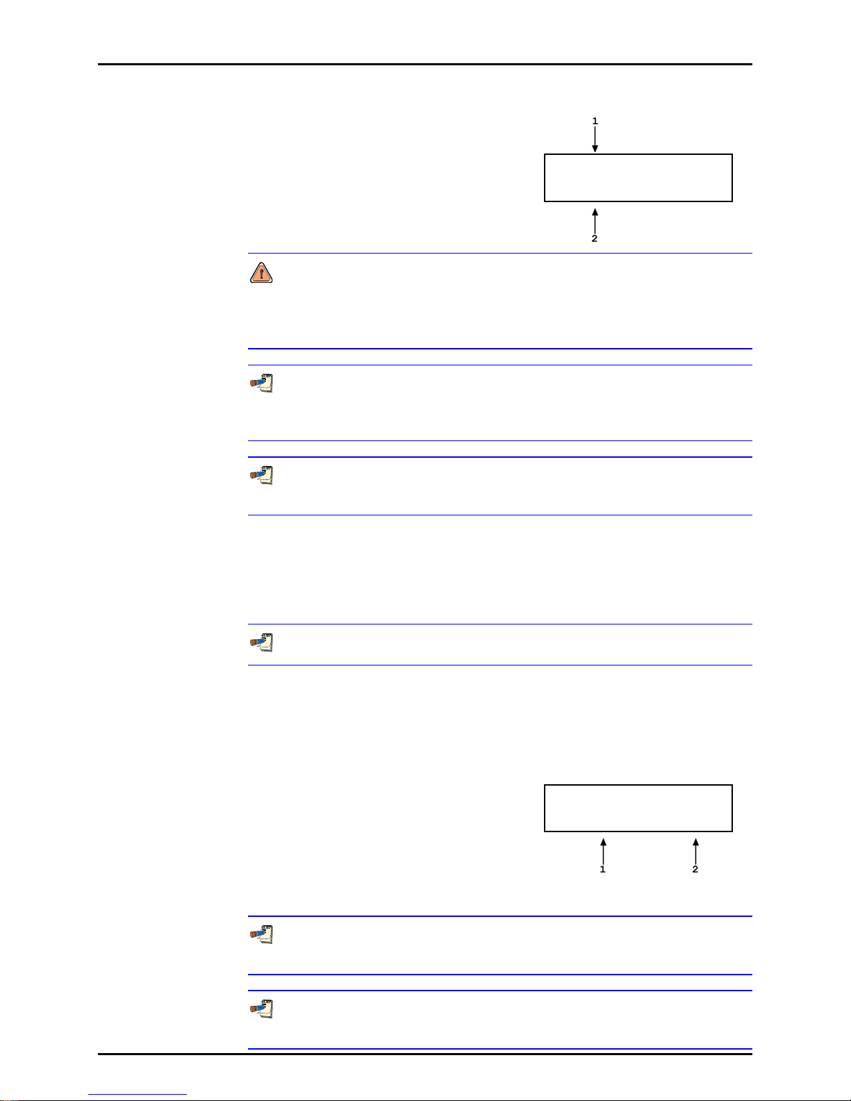
RPM3™ OPERATION AND MAINTENANCE MANUAL
H
With the RPT DISPLAY active the main run screen is:
1. Active RPT display.
2. Inactive RPT display.
* 99.1135 psi a zH3
* 2350.23 psi g zL2
If the inactive RPT is equipped with SDS Self Defense System (see Section
3.1.2.6), SDS will almost certainly be ON when the RPT DISPLAY is activated.
SDS can be defeated on the inactive RPT by pressing [SPECIAL] and
selecting <2SDS> (see Section 3.4.2).
With the RPT display active, executing a range change to a range on the
inactive RPT causes the range change to occur making the inactive RPT the
active RPT. The DISPLAY defaults back to Rate.
To go to a DISPLAY other than RPT, press [DISPLAY] and make a new
DISPLAY choice (see Section 3.2.6).
3.2.6.5 HI/LO
PURPOSE
To activate the HI/LO DISPLAY.
See Section 3.2.6.
OPERATION
To activate the HI/LO DISPLAY press [DISPLAY] and select <5Hi/Lo>.
Selecting <5Hi/Lo> resets the Hi/Lo values and returns to the main run screen
with the HI/LO DISPLAY active.
With the Hi/Lo DISPLAY active the main run screen is:
* 99.1135 psi a zH3
1. Lowest pressure observed since Hi/Lo reset.
2. Highest pressure observed since Hi/Lo reset.
99.1135 LL99.1135
The Hi/Lo values change each time a new Hi or Lo pressure is observed.
The Hi/Lo record can be reset at any time by pressing [ENTER]. This allows a
Hi/Lo reset without going back through the DISPLAY menu.
If the pressure measurement unit, mode (gauge or absolute) or range is
changed while the HI/LO DISPLAY is active, Hi/Lo resets.
© 1998-2002 DH Instruments, Inc. Page 34

3. OPERATION
F
To go to a DISPLAY other than HI/LO, press [DISPLAY] and make a new
DISPLAY choice (see Section 3.2.6).
3.2.6.6 FREEZE
PURPOSE
See Section 3.2.6.
OPERATION
To activate the FREEZE DISPLAY press [DISPLAY] and select <6Free>.
Selecting <6Free> returns to the main run screen with the FREEZE DISPLAY
active.
With the FREEZE DISPLAY active the main run screen is:
* 99.1135 psi a zH3
To activate the FREEZE DISPLAY.
1. Pressure measured by active range of RPM3
when [ENTER] was pressed in the current
pressure units (displays 0.00 by default when
Freeze DISPLAY is first activated).
99.2133
Pressing [ENTER] causes the current pressure measured by the active RPM3
range to be captured and displayed.
If the pressure measurement unit, mode (gauge or absolute) or range is
changed while the FREEZE DISPLAY is active, the Freeze value defaults back
to zero.
To go to a DISPLAY other than FREEZE, press [DISPLAY] and make a new
DISPLAY choice (see Section 3.2.6).
3.2.6.7 CLEAN
PURPOSE
To activate the CLEAN DISPLAY.
See Section 3.2.6.
OPERATION
To activate the CLEAN DISPLAY press [DISPLAY] and select <7Clean>.
Selecting <7Clean> returns to the main run screen with the CLEAN DISPLAY
active.
Page 35 © 1998-2002 DH Instruments, Inc.
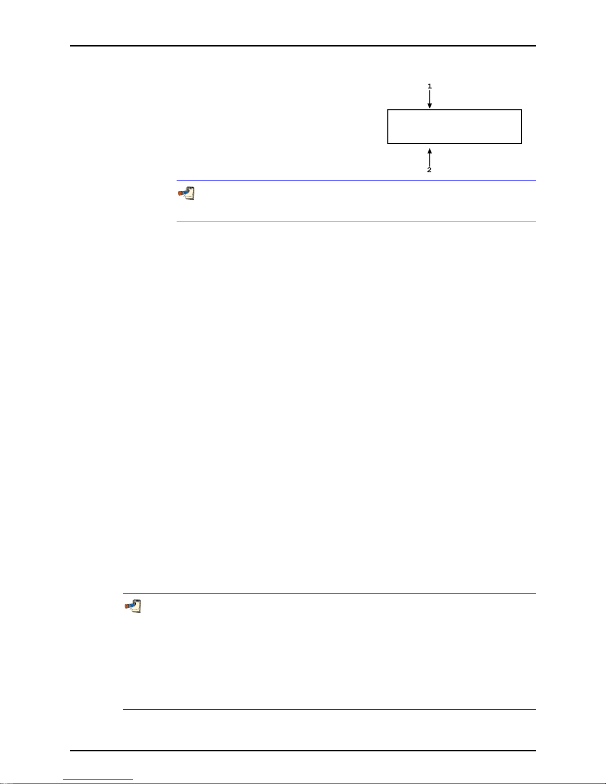
RPM3™ OPERATION AND MAINTENANCE MANUAL
With the CLEAN DISPLAY active the main run screen is:
1. Conventional main run screen first line.
2. “Clean” second line.
* 99.1135 psi a zH3
To go to a DISPLAY other than CLEAN, press [DISPLAY] and make a new
DISPLAY choice (see Section 3.2.6).
3.2.7 [HEAD]
PURPOSE
To cause a pressure value representing a difference in height to be added to the pressure
measured by the RPM3 reference pressure transducer (RPT).
PRINCIPLE
RPM3’s RPTs measure gauge or absolute pressure at the height of the rear panel TEST
port. Frequently, when performing a calibration or test, the device or system under test is at
a different height than the RPM3’s TEST port. This difference in height, frequently called
head, can cause a significant difference between the pressure measured by the RPM3 at its
TEST port height and the pressure actually applied to the device under test located at a
different height. In this case, it is useful to make a head correction to the pressure measured
by the RPM3 RPT at its TEST port in order to accurately predict the pressure actually applied
at a different height. The HEAD function allows head corrections to be applied automatically
for a variety of fluids based on operator entry of the nature of the pressurized fluid and the
height difference.
RPM3 can accurately determine head pressures for gas (nitrogen, helium and air) and liquids
(oil, water) as the pressurized medium. In calculating the head value, standard gravity
(9.80665 m/s2) is used. Gas densities are calculated from standard density correcting for
temperature of 20 °C and the measured pressure using the gas’s compressibility factor to
1 500 psi (10 MPa) and extrapolated above 1 500 psi. Above 1 500 psi, gas heads should be
minimized to minimize uncertainties due to head corrections. Oil density is taken at
850 kg/m3, the density of typical calibration oils at 20 °C. Water density is taken at
998.2321 kg/m3 (20 °C). A custom liquid density may also be specified.
The HEAD function key is used to specify the difference between the RPM3 TEST port and
the test height. The height units and the head fluid are specified by pressing [SETTINGS]
and selecting <1Head> (see Section 3.3.1).
Use of the HEAD function to assure in tolerance measurements when gas is the test
fluid is most important at low absolute pressures. In this case, specifying the head
height within ± 4 in. (10 cm) is adequate to assure that, even in the worst case, the
uncertainty on the head correction will be insignificant relative to the tolerance on the
RPM3 measurement. Use of the HEAD function to assure in tolerance measurements is
particularly critical when a liquid is the test fluid due to the high density of liquids.
To determine when and how precisely a head correction for liquids must be made,
0.03 psi/inch (90 Pa/cm) may be used as an estimation of the liquid head value.
© 1998-2002 DH Instruments, Inc. Page 36

3. OPERATION
9
OPERATION
To access the HEAD function, press [HEAD]. The display is:
Edit head height:
1. Test fluid currently specified for the head correction.
2. Entry field for head height (1 to 999 cm or in).
5 cm N2
Entering a value of zero turns the HEAD function OFF. Entering a value other than zero
turns the HEAD function on using the height entered. Pressing [ESCAPE] returns to the
main run screen with NO change to the current head setting.
The reference height of the RPM3 pressure measurement is the middle of the RPM3 TEST
port. The head height should be entered as a positive value if the device or system under
test is higher than the RPM3 and negative if it is lower.
The HEAD function is NOT range specific. The HEAD ON or OFF status remains the same
as ranges are changed; edits made to the head specifications are independent of range.
When the HEAD function is ON (head value ¹0), this is indicated by <h> in the right side
of the top line of the main run screen (see Section 3.1.1). When the HEAD function is OFF,
the <h> is NOT shown.
To change units of head height between inches
and centimeters and to change the test gas
species, press [SETTING] and select <1Head>
(see Section 3.3.1).
...................
Reference
Level
(TEST Port)
-
3.2.8 [SDS] (SELF DEFENSE SYSTEM)
PURPOSE
To activate SDS on all reference pressure transducers (RPTs). To defeat SDS on the
Page 37 © 1998-2002 DH Instruments, Inc.
active RPT.
SDS is present only on RPTs designated A1500 or lower.
The [SDS] key should be used with care to avoid accidentally overpressuring an RPT.
Always double check to ensure that the pressure applied to the RPT TEST port is lower
than the maximum pressure acceptable to the RPT before defeating SDS.

RPM3™ OPERATION AND MAINTENANCE MANUAL
PRINCIPLE
SDS is a self defense system to protect RPM3 RPTs from overpressure.
When SDS is ON for an RPT, that RPT is isolated from the TEST port and opened to the
VENT port. When SDS is ON, the RPT cannot measure the pressure connected to the TEST
port so SDS must be defeated TEST port pressure can be measured by the RPT. The SDS
function key allows SDS on the active RPT to be defeated.
The SDS function can also be used to turn SDS ON as might be desired when leaving RPM3
at rest or when a possible overpressure situation is anticipated. Pressing [SDS] always turns
on any SDS systems that are OFF.
See Section 3.1.2.6 for additional information on the SDS system and Section 1.2.3 for
schematics of SDS configuration.
SDS ON is indicated by <***SDS***> flashing in the current measured pressure display
field. When SDS is ON, the RPT is isolated from the TEST port and the displayed
pressure is the pressure at the VENT port.
OPERATION
Though the SDS self defense system includes features to protect RPTs against
overpressure, SDS should NOT be considered a fail-safe overpressure protection system.
SDS cannot guarantee that overpressure damage will NOT occur. SDS automatic
activation may protect an RPT in case of accidental overpressure but conventional
measures for protecting against overpressure should always be followed. Damage to RPTs
due to overpressure is NOT covered by the RPM3 product warranty even when SDS is present.
The maximum pressure that should be applied to an RPM3 test port when SDS is ON is
2 000 psi (13 MPa).
When SDS is turned on with a pressure applied, a valve shuts isolating the RPT from the
TEST port. A second valve vents the RPT to atmosphere through the VENT port. If the
pressure applied at the time SDS is turned ON is less than 250 psi (1 700 kPa), the VENT
valve will open causing sudden release of pressure through the VENT port and returning
the RPT to atmospheric pressure. If the pressure applied at the time SDS is turned ON
is greater than 250 psi, the VENT valve may NOT open. In this case, to vent the RPT,
remove the pressure from the test port. This will cause the SDS TEST port isolation valve
to open partially, reducing pressure under 250 psi at which time the SDS VENT valve will open.
Pressing [SDS] always turns ON any SDS system that is OFF. In a dual RPT RPM3, even
if the active RPT has NO SDS, pressing [SDS] will turn SDS ON for the inactive RPT if
SDS is present.
© 1998-2002 DH Instruments, Inc. Page 38

3. OPERATION
D
Use [SDS] to defeat SDS if it is ON for the active RPT and/or to turn SDS ON for the active
and inactive RPT if present.
When [SDS] is pressed, there are three possible results depending whether the active RPT
is SDS equipped and, if so, whether SDS is OFF or ON.
1. If the active RPT IS NOT SDS equipped: <No SDS on RPT> is displayed for 5 seconds
and operation returns to the main run screen.
2. If the active RPT IS SDS EQUIPPED and SDS on the active RPT is OFF: SDS is
turned ON and operation returns to the main run screen.
3. If the active RPT IS SDS EQUIPPED and SDS on the active RPT is ON.
The opportunity to defeat SDS is presented. The display is:
1. Maximum acceptable pressure (Pmax!) for active range
(always absolute on an absolute RPT and gauge on a
gauge RPT).
Pmax! 510 psi a H3
efeat SDS? 1no 2yes
Check that the pressure applied to the TEST port does NOT exceed the Pmax! value for the
active range. Select <1no> to return to the main run screen without defeating SDS. Select
<2yes> to defeat SDS and return to the main run screen with SDS defeated (the active RPT
open to the TEST port).
Defeating SDS with a pressure greater than Pmax! applied to the test port may cause
overpressure damage to the RPT.
The SDS key is also the [2] key which is pressed to select <2Yes> to defeat SDS. Thus,
SDS can be defeated by two rapid presses of the SDS function. Use this feature to
conveniently defeat SDS but always check that the pressure connected the TEST port
does NOT exceed Pmax! before doing so.
When changing ranges changes the active RPT, SDS is automatically turned ON for the
RPT that is being changed from, leaving the inactive RPT with SDS ON.
Direct control over SDS for both the Lo and Hi RPTs if present, regardless of which RPT is
currently active, is provided by pressing [SPECIAL] and selecting <2SDS> (see Section
3.4.2). Direct SDS control should only be used with caution and by qualified operators,
as the chances of accidental overpressure to an RPT are increased.
Page 39 © 1998-2002 DH Instruments, Inc.

RPM3™ OPERATION AND MAINTENANCE MANUAL
3.2.9 [AutoZ]
PURPOSE
To run the AutoZ function that rezeros the active range.
See Section 3.4.1 for an explanation of AutoZ principles.
To assure operation within “with autozero” measurement accuracy specifications
(see Section 1.2.2), AutoZ should be run regularly to update the value of ZOFFSET.
For absolute measurement mode, it is recommended that AutoZ be run at least every
30 days or when RPM3 has been exposed to temperature changes
exceeding
± 20 ºC (36 ºF). For gauge measurement mode, it is recommended that AutoZ be run
each time the range or measurement mode is changed and each time the RPT is known to
be in a vented condition.
PRINCIPLE
Run AutoZ is the function by which the current RPT reading is compared to ZSTD and a new
value of ZOFFSET representing RPT zero drift is determined and applied (see Section 3.4.1).
OPERATION
To run AutoZ, press [AutoZ] from the main run screen. If the measurement mode of the
active range is gauge, ZSTD is atmospheric pressure (zero gauge) and AutoZ runs
automatically (see Section 3.2.9.1). If the measurement mode of the active range is
absolute, the source of ZSTD must be specified when AutoZ is run (see Section 3.2.9.2).
Run AutoZ and the value of ZOFFSET that it updates are specific to each range and
operating mode (gauge or absolute).
3.2.9.1 RUNNING AUTOZ IN GAUGE MEASUREMENT MODE
PURPOSE
To rezero, redetermine ZOFFSET, for the active RPT and range in gauge
measurement mode.
See Section 3.4.1 for an explanation of AutoZ principles.
OPERATION
For the AutoZ function key to run AutoZ, AutoZ must be turned ON for the
active range and measurement mode. AutoZ ON is indicated by <z>
displaying to the left of the range designator on the first line of the main
run screen. AutoZ ON and OFF is set by pressing [SPECIAL] and selecting
<1AutoZ> (see Sections 3.4.1 and 3.4.1.1). If AutoZ is OFF for the active
range, and measurement mode, <AutoZ disabled> is displayed when [AutoZ]
is pressed.
© 1998-2002 DH Instruments, Inc. Page 40

3. OPERATION
To run AutoZ in gauge measurement mode, press the [AutoZ] function key from
the main run screen. <Running gauge AutoZ> is displayed briefly before
returning to the main run screen.
Before running AutoZ in gauge mode, ensure that the pressure applied to
the RPT is truly zero gauge (atmospheric pressure). For very low gauge
pressure ranges, better results may be obtained by connecting the TEST
port to the TEST (-) port to be sure that the differential is truly zero. If
running AutoZ in gauge mode results in a zero offset that RPM3 considers
unusually large, <Confirm 0 gauge P!> is displayed when [AutoZ] is pressed.
Check that the TEST port (and TEST (-) port if the RPT is a gauge RPT) are
fully open to atmosphere and press [ENTER] to continue or [ESCAPE] to
abort. Running AutoZ without zero applied to the RPT may result in out of
tolerance measurements.
If a HEAD correction is active as indicated by <h> in the first line of the
display, RPM3 may NOT indicate zero even right after running AutoZ in gauge
mode. The head correction is momentarily disabled when AutoZ is run. The
value displayed just after RPM3 is zeroed is the value of the current head
correction which is the pressure applied at the head height when the
pressure at the RPM3 reference level is zero gauge (see Section 3.2.7).
3.2.9.2 RUNNING AUTOZ IN ABSOLUTE MEASUREMENT MODE
PURPOSE
To rezero (redetermine ZOFFSET) for the active RPT and range in absolute
measurement mode.
See Section 3.4.1 for an explanation of AutoZ principles.
OPERATION
For the AutoZ function key to run AutoZ, AutoZ must be turned ON for the
active range and measurement mode. AutoZ ON is indicated by <z>
displaying to the left of the range designator on the first line of the main
run screen. AutoZ ON and OFF is set by pressing [SPECIAL] and selecting
<1AutoZ> (see Section 3.4.1.1). If AutoZ is OFF for the active range, and
measurement mode, <AutoZ disabled> is displayed when [AutoZ] is pressed.
Page 41 © 1998-2002 DH Instruments, Inc.

RPM3™ OPERATION AND MAINTENANCE MANUAL
To run AutoZ in absolute measurement mode, press [AutoZ] from the main run
screen. The display is:
1. Active range.
2. Current measurement mode (gauge or abs for
absolute).
3. Selection of source of ZSTD for ZOFFSET
determination.
AutoZ H3 abs by:
1Entry 2COM2 3RngL3
|__________________ _________________|
Selecting <1Entry> allows the value of ZSTD to be entered from the front panel
keypad (see Section 3.2.9.2).
Selecting <2COM2> allows the value of ZSTD to be read automatically from an
RPM1, RPM2 or RPM3 connected to RPM3’s COM2 serial port (see Section
3.2.9.2).
Selecting <3RngL3> allows the value of ZSTD to be read automatically from the
Lo RPT Range 3 (available only if the active RPT is a Hi absolute RPT and there
is a Lo absolute RPT) (see Section 3.2.9.2).
Allow the RPM3 to stabilize at atmospheric pressure and ambient
temperature for 5 to 10 minutes before running AutoZ in absolute mode.
If running AutoZ results in values of ZOFFSET that are greater than ± 0.01 %
FS (± 0.05 % FS for b Type RPTs) of the active RPM3 measurement range,
the RPM3 and/or the source of ZSTD may be out of tolerance or the AutoZ
process may have been faulty. Before activating a new ZOFFSET greater
than ± 0.01 % FS (± 0.05 % FS for b Type RPTs) of the active RPM3 range,
check to be sure that both the RPM3 and the source of ZSTD were in good
working order, properly vented to stable atmospheric pressure, at the same
height, and reading in the same pressure units when AutoZ was run.
When the run AutoZ selection is made, if a HEAD correction is currently
The value of ZOFFSET in absolute mode is NOT necessarily be exactly equal
Run AutoZ by Entry
AutoZ by entry allows the value of ZSTD (see Section 3.4.1) to be entered
manually. This provides a simple way of autozeroing relative to an independent
reference device such as a house barometer that does NOT interface directly
with RPM3.
© 1998-2002 DH Instruments, Inc. Page 42
active (see Section 3.2.7), the head correction is temporarily disabled to
avoid “zeroing out” the head correction.
to the difference between the current reading and ZSTD if ZNATERR is NOT
zero (see Section 3.4.1). For the same reason, RPM3 may NOT read exactly
the same value as ZSTD even right after AutoZ has been run.

3. OPERATION
To access run AutoZ by entry press [AutoZ] from the main run screen while in
absolute measurement mode. Then select <1Entry>. The display is:
1. Pressure reading, units and mode of the
active RPT range.
2. Active range indicator.
3. Entry field for the value of ZSTD.
Enter the value of ZSTD in the current
units. The next display is:
14.104 psi a H3
ZSTD: 0.0000
Old ZOFFSET: 0.0 Pa
New ZOFFSET: 6.5 Pa
The old ZOFFSET is the ZOFFSET currently used.
The new ZOFFSET is the ZOFFSET resulting from this execution of run AutoZ.
Press [ENTER] to activate the new ZOFFSET and return to the main run screen.
Press [ESCAPE] to maintain the old ZOFFSET and return to the main run
screen.
The value of ZOFFSET is always displayed and entered in Pascal (Pa).
The value of ZSTD must be entered in the current pressure units or the
calculation of ZOFFSET will be incorrect.
Run AutoZ by COM2
AutoZ by COM2 allows the value of ZSTD (see Section 3.4.1) to be read
automatically from a DHI RPM1, RPM2 or RPM3 connected by RS-232 interface
to the RPM3 COM2 port.
To access <run AutoZ by COM2>, press [AutoZ] from the main run screen
while in absolute measurement mode. Then select <2COM2>. The display is:
1. Pressure reading, units and mode of the
active RPT range.
2. Active range indicator.
3. Pressure reading of the RPM connected to
RPM3’s COM2 port.
When ready, press [ENTER]. The next
display is:
14.104 psi a H3
ZSTD: 14.102
Old ZOFFSET: 0.0 Pa
New ZOFFSET: 13.8 Pa
The old ZOFFSET is the ZOFFSET currently used.
The new ZOFFSET is the ZOFFSET resulting from this execution of run AutoZ.
Press [ENTER] to activate the new ZOFFSET and return to the main run screen.
Page 43 © 1998-2002 DH Instruments, Inc.

RPM3™ OPERATION AND MAINTENANCE MANUAL
Press [ESCAPE] to maintain the old ZOFFSET and return to the main run
screen.
For RPM3 to communicate with an RPM connected to its COM2 port, the
RPM3 and the RPM RS-232 interfaces must be set up properly (see Section
3.4.4). If the RPM3 is unable to locate an RPM ON COM2 when running
AutoZ by COM2, it times out after 6 seconds and displays <RPM NOT
detected>.
The value of ZOFFSET is always displayed and entered in Pascal (Pa).
Run AutoZ by RngL3
The AutoZ by RngL3 choice is only available if the active RPT is an absolute,
Hi RPT and there is also an absolute Lo RPT in the RPM3. Run AutoZ by RngL3
allows AutoZ to be run on a Hi RPT range using Lo RPT range 3 (L3) as the
source of ZSTD (see Section 3.4.1).
To access <run AutoZ by RngL3>, press [AutoZ] from the main run screen
while in absolute measurement mode. Then select [3RngL3]. The display is:
1. Pressure reading, units and mode of the
active Hi RPT range.
2. Active range indicator.
3. Pressure reading of Lo RPT range 3 (L3).
When ready, press [ENTER]. The next
display is:
14.104 psi a H3
ZSTD: 14.102
Old ZOFFSET: 0.0 Pa
New ZOFFSET: 13.8 Pa
The old ZOFFSET is the ZOFFSET currently used.
The new ZOFFSET is the ZOFFSET resulting from this execution of run AutoZ.
Press [ENTER] to activate the new ZOFFSET and return to the main run screen.
Press [ESCAPE] to maintain the old ZOFFSET and return to the main run
screen.
Before running AutoZ by Lo RPT, be sure that range L3 of the Lo RPT is
correctly calibrated and autozeroed.
If you are running AutoZ on the Hi and Lo RPTs of an RPM3 and using run AutoZ
The value of ZOFFSET is always displayed and entered in Pa.
© 1998-2002 DH Instruments, Inc. Page 44
by RngL3 to autozero the Hi RPT, be sure to run AutoZ on the Lo RPT first.

3. OPERATION
4
1
1
1
1
3.3 [SETUP] MENU KEY
PURPOSE
The [SETUP] key accesses a menu of commonly used RPM3 functions and features that do NOT have
direct function keys.
Select <Head> To change the height units and fluid (see Section 3.3.1)
Select <PresU> To customize the choices available under [UNIT] and to set up User Defined Units
(see Section 3.3.2)
Select <ReadRt> To turn ON and OFF RPM3’s automated, rate of change dependent, reading
integration time feature (see Section 3.3.3)
Select <Stab> To view and adjust the stability limit that is the criterion for the Ready (<*>)/Not Ready
(<
> or < >) condition (see Sections 3.3.4 and 3.1.2.4)
Select <Leak> To run an automated leak checking function (see Section 3.3.5)
OPERATION
To access the SETUP menu, press [SETUP] from the main run
screen. The display is:
3.3.1 HEAD
PURPOSE
To specify the configuration of the HEAD function (see Section 3.2.7) including the length unit
of measure for head height entry and the test fluid for head pressure calculations.
OPERATION
From the main run screen, press [SETUP] and select
<1Head>. The display is:
Select the desired head height unit. The next
display is:
If <1Gas> is selected, the display offers the choice of
three gasses. Making a gas selection returns to the
main run screen with that gas active for the HEAD
function.
If <2Liquid> is selected the display offers the choice
of oil, water or a user defined liquid. If the user defined
liquid is selected, its density must be specified.
Making a liquid selection returns to the main run
screen with that liquid active for the HEAD function.
1Head 2PresU 3ReadRt
Stab 5Leak
Head height unit:
in 2cm
Head medium:
Gas 2Liquid
Gas type:
N2 2He 3Air
Liquid type:
Oil 2H2O 3User
Page 45 © 1998-2002 DH Instruments, Inc.

RPM3™ OPERATION AND MAINTENANCE MANUAL
3
1
3.3.2 PRESU
PURPOSE
To customize the selection of pressure units that are available for selection from the UNIT
function key.
PRINCIPLE
The UNIT function key makes available a choice of six default pressure units (US or SI
depending on whether the RPM3 has been factory set as US or SI) (see Section 3.2.2).
RPM3 also supports many commonly used units in addition to those included in the default
set up. These units can be made available for active selection by customizing the UNIT
function by pressing [SETUP] and selecting <2PresU>. This allows RPM3 to offer a very
wide selection of units while simplifying day to day operation. The typical user will customize
the UNIT function key to support his/her six most commonly used units.
OPERATION
To customize the UNIT function key, from the main run screen press [SETUP] and select
<2PresU>. The display is:
1. Entry field to select which unit position (1 to 6) of the UNIT
function key menu is to be changed.
Set up user unit #6
Enter the number of the unit position that you would
like to change. The display becomes:
Unit #6 1SI 2Other
Altitude 4User
Select the desired pressure unit category (SI units include units based on SI such as mmHg),
then select the desired unit from the unit menu.
Table 11 PresU - Available Units
1SI 2other 3altitude 4user
1Pa
2kPa
3mPa
4mbar
5bar
6mmHg
7mmWa
1psi
2psf
3inHg
4inWa
5kcm2
1feet
2meters
1user
If <4user> was selected, the user unit must be defined. The display is:
Define user unit:
.000000 Units/Pa
1. Entry field.
Enter the number of user units per Pascal (Pa) in the entry field. Pressing [ENTER] defines
the user unit and returns to the <Set up unit #> screen.
© 1998-2002 DH Instruments, Inc. Page 46

3. OPERATION
1
The user defined unit can be assigned a user defined label using the UNIT: USER remote
command (see Section 4.4.2.).
See Section 7.1 for the pressure unit conversion factors used by RPM3.
3.3.3 READRT (READ RATE)
PURPOSE
To turn ON and OFF RPM3’s automated, rate of change dependent, reading integration
rate feature.
PRINCIPLE
To obtain maximum resolution from RPM3 RPT pressure measurements, an integration time
of about 1 second per reading is used. In most situations, maximum accuracy is needed
when pressures are stable so a relatively slow reading rate presents NO disadvantage.
However, when pressure is changing quickly, more rapid pressure updates are usually more
important than obtaining maximum accuracy on individual readings. The RPM3 read rate
function automatically adjusts pressure measurement integration time depending on the rate
of change of pressure. When pressure is changing rapidly, reading rate is increased. When
pressure is evolving slowly, reading rate is decreased and maximum accuracy is obtained.
When the automated read rate function is ON, three pressure rate of change dependent read
rates are used. The result is three display update rates:
Table 12 READRT - Display Update Rates
PRESSURE
RATE OF CHANGE
> 3 % FS/s
> 0.5 and < 3 % FS/s
< 0.5 % FS/s
DISPLAY
UPDATE
≈ 0.2 s
≈ 0.5 s
≈ 1 s
For situations in which an evolving reading rate is NOT desired, the RPM3 automated read
rate function can be turned OFF. In this case, the reading rate is always the high resolution
rate of about 1 reading per second.
OPERATION
To turn the automated read rate function ON or OFF press [SETUP] and select <3ReadRt>.
Auto read rate: H3
The display is:
no 2yes
The cursor is on the current selection.
Selecting <1on> activates the automated reading rate and returns to the main run screen.
Selecting <2off> turns OFF the automated reading rate and returns to the main run screen.
The default RPM3 condition is auto read rate ON.
Auto read rate ON/OFF is NOT range specific. Turning auto read rate ON or OFF in one
range turns it ON or OFF for all RPM3 ranges.
Page 47 © 1998-2002 DH Instruments, Inc.
RPM3™ OPERATION AND MAINTENANCE MANUAL
0
3.3.4 STAB (STABILITY)
PURPOSE
To view and/or adjust the stability test that is the Ready (See Section 3.1.2.4.)/Not Ready
(<
↑> or <↓>) criterion for the active RPT and range.
See Section 3.1.2.4.
PRINCIPLE
RPM3 continuously monitors the rate of change of pressure measured by the active RPT and
range and compares this rate to the stability limit to make a Ready (<*>)/Not Ready (<
determination (see Section 3.1.2.4). The stability function allows the stability limit to be
adjusted by the user to increase or decrease the stability required for a Ready <*> condition to
occur.
The default stability limit is ± 0.005 % FS of the active range.
↑> or <↓>)
The stability limit is separate and different from the Rate DISPLAY function (see Section
3.2.6.2) which allows the current rate of change of pressure to be displayed.
OPERATION
To adjust the stability limit press [SETUP] and select <4Stab>. The display is:
Stability limit: H3
1. Entry field for setting the desired stability limit. Recalls the
default stability limit or the last custom stability limit for the
active range in the current pressure units for that range.
.0015 psi/s
Edit the desired stability limit setting if desired. Pressing [ENTER] activates the stability limit
for the range and returns to the main run screen.
The stability setting is range specific. Changes made in one range do NOT affect any
other range.
3.3.5 LEAK (LEAK CHECK)
PURPOSE
To run an automated leak check routine using RPM3 to measure the total pressure change
and average rate of change over a period of time; to edit the leak check time.
PRINCIPLE
The Leak Check function is provided to assist in using RPM3 to measure leaks by measuring
pressure changes.
The principle of the Leak Check function is the measurement of pressure increase or decrease.
The Leak Check function allows a leak check time to be set. The total pressure change and
the average rate of change over the leak check time are calculated and displayed.
© 1998-2002 DH Instruments, Inc. Page 48

3. OPERATION
1
1
Changing the pressure in a test system causes adiabatic temperature changes in the gas
that need to have dissipated before a valid leak measurement can be made. In general,
a 0.5 to 1 minute wait before running a leak check is adequate to allow the adiabatic
temperature change to dissipate and valid leak measurements to be made. However,
stabilization time may be much longer with liquid test media, as volumes increase and as
pressures increase.
OPERATION
To access the LEAK function press [SETUP] and select <5Leak>.
Leak Check H3
The display is:
run 2view
Select <2view> to view the results of the last leak check executed. Results screen displays
<Data NOT available> briefly and returns to main run screen if NO leak check data is stored
(e.g., if the RPM3 has never run a leak test or a reset has cleared previous leak test results).
Pressing [ENTER] or [ESCAPE] returns to the main run screen.
Leak check is range specific in the sense that leak check is run using the active range.
However, only one set of leak check results is maintained in memory and each leak test
completed overwrites the memory. View leak check always shows the results of the last
leak check run regardless of the range that is now active. The results screen includes the
range indicator to indicate the range in which the leak check was run.
Select <1run> to run a leak check and/or to edit the leak check time. The display is:
Set leak check time:
5 s
1. Edit field for leak check time in seconds (1 min, 999 max).
Edit the leak check time if desired. Press [ENTER] to run leak test. The display is:
1. Standard main run screen first line.
2. Indication that leak test is running and countdown of time
remaining(s).
99.1135 psi a zH3
Leak testing 13 s
Pressing [ESCAPE] during the countdown offers a leak check abort option to return to the
main run screen or continue leak test. Pressing [ENTER] during the leak check countdown
causes the countdown to reset to start.
Page 49 © 1998-2002 DH Instruments, Inc.

RPM3™ OPERATION AND MAINTENANCE MANUAL
7
Once the leak check countdown has completed, the results screen is displayed:
1. Net change in pressure over the leak check time period.
2. Indicator of range in which leak check was run.
3. Average rate of change of pressure over the leak check
time period.
ΔP 0.0035 psi H3
Rate –0.0002 /sec
Pressing [ENTER] from the leak check results screen following execution of a leak check
starts a new leak check routine directly without having to go through the leak check menu.
Pressing [ESCAPE] returns to the main run screen.
Pressing [ENTER] while counting down a leak check or when in leak check results screen
starts a new leak check sequence.
3.4 [SPECIAL] MENU KEY
PURPOSE
Pressing [SPECIAL] accesses a menu of RPM3 functions and settings that are less commonly or NOT
normally used in regular operation. These include:
Select <AutoZ> Turn AutoZ ON/OFF, view and edit ZOFFSET values (see Section 3.4.1)
Select <SDS> Turn SDS ON/OFF independently of the [SDS] key (see Sections 3.1.2.6 and 3.4.2)
Select <ATM> View the current reading of the on-board barometer (see Section 3.4.3)
Select <Remote> Set up RPM3 serial and GPIB (IEEE-488) interfaces (see Section 3.4.4)
Select <Reset> Access and execute a number if reset options (see Section 3.4.5)
Select <Cal> View and adjust RPM3 RPT and barometer calibration coefficients (see Sections 3.4.6 and 5.2)
Select <Intern> View and set screen saver, keypad sounds, time and ID features (see Section 3.4.7)
Select <Level> View and change User Level protection of RPM3 functions (see Section 3.4.8)
Select <Log> View the RPM3 incident log (see Section 3.4.9)
OPERATION
To access the SPECIAL menu, press [SPECIAL] from the main run screen.
1AutoZ 2SDS 3Atm
The display is:
4Remote 5Reset 6Cal
Prefs 8Level 9Log
Some screens, such as the SPECIAL menu go beyond the two lines provided by the display. This is
indicated by a flashing arrow in the second line of the display. Use the [ ] and [ ] keys to move
the cursor to access the lines that are NOT visible or directly enter the number of the hidden menu
choice if you know it.
© 1998-2002 DH Instruments, Inc. Page 50

3. OPERATION
3.4.1 AUTOZ
PURPOSE
To manage the AutoZ function for the active RPT and range including turning AutoZ
ON/OFF, viewing and editing AutoZ values.
To run AutoZ (rezero), use the [AutoZ] direct function key (see Section 3.2.9).
PRINCIPLE
How AutoZ Works
The main component of the change over time of the RPM3 RPTs is zero drift or offset,
independent of span. Rezeroing RPM3 RPTs relative to a stable reference between
recalibrations allows higher measurement accuracy specifications to be maintained with a
longer interval between full recalibrations. The RPM3 autozero function (AutoZ) provides full
on-board support for the rezeroing process to simplify its application by the user.
The autozeroing function uses four parameters:
1. ZSTD: The value of the autozero pressure as indicated by the reference autozero
device.
For absolute RPTs in absolute measurement mode
: The autozero pressure is always
atmospheric pressure and the ZSTD value can be supplied in one of three ways:
a) By manual entry
b) From a DHI RPM connected to the RPM3 COM2 port
c) From a Lo absolute RPT if one is available
For gauge RPTs or absolute RPTs in gauge measurement mode
: The autozero
pressure is always zero (atmospheric pressure) which is available by definition any time
the RPT is vented to atmosphere.
2. ZCURERR: The difference between ZSTD and the RPT indication at the autozero
pressure at some time after the RPT has been calibrated (ZCURERR = RPT reading
w/out ZOFFSET- ZSTD).
3. ZNATERR: The difference between ZSTD and the RPT indication at the autozero
pressure just after the RPT has been calibrated (ZNATERR = RPT reading w/out
ZOFFSET - ZSTD). This value, when measured just after RPT calibration, is referred to
as the natural error at the autozero pressure. Because NO RPT is perfectly linear and
ZSTD is NOT perfectly accurate, the disagreement between the RPT reading and ZSTD
at the autozero pressure is unlikely to ever be zero (except for gauge RPTs for which the
zero point is forced at calibration).
4. ZOFFSET: ZCURERR corrected for ZNATERR, represents the drift of the RPT relative
to the reference (ZOFFSET = ZCURERR - ZNATERR). The active RPT reading,
adjusted by ZOFFSET, is the autozeroed RPT reading (e.g., the RPT reading corrected
for zero drift since it was calibrated). For an absolute RPT used in gauge mode,
ZOFFSET also includes the value of atmospheric pressure that is being subtracted to
arrive at gauge pressure.
The AutoZ function manages the determination, storage and application of ZNATERR and
ZOFFSET individually for each RPM3 range and measurement mode. ZNATERR error is
determined at the time of calibration (see Section 5.2). ZCURRERR and ZOFFSEST
between calibrations are determined by running AutoZ using the [AutoZ] direct function key
(see Section 3.2.9).
Page 51 © 1998-2002 DH Instruments, Inc.

RPM3™ OPERATION AND MAINTENANCE MANUAL
AutoZ On/Off
The AutoZ function can be turned ON and OFF. When AutoZ is ON, ZOFFSET is always
applied to the pressure measured by RPM3 and new values of ZOFFSET can be determined
by running AutoZ using the [AutoZ] key. When AutoZ is OFF, ZOFFSET is NOT applied
(except for an absolute RPT in gauge mode for which ZOFFSET is the current value of
atmospheric pressure which is always subtracted to achieve gauge pressure) and AutoZ
cannot be run (see Section 3.4.1.1). In gauge mode, turning AutoZ OFF turns OFF the
dynamic compensation for atmospheric pressure.
Gauge Mode with an Absolute RPT, Dynamic Compensation for Atmospheric Pressure
RPM3 supports gauge pressure measurements with an absolute RPT by subtracting the
value of atmosphere (tare) from the RPT’s absolute measurement to arrive at a gauge value.
The appropriate tare value changes with the natural evolution of atmospheric pressure at a
given location. For this reason, the value of the tare should be redetermined by running
AutoZ (see Section 3.2.9) each time the RPT is vented to atmospheric pressure. However, if
atmospheric pressure changes significantly between vented conditions, these changes in
atmospheric pressure are NOT eliminated by retaring. To compensate for changes in
atmospheric pressure between autozeroing (taring) opportunities, dynamic atmospheric
pressure compensation is used.
To minimize zero errors due to the evolution of atmospheric pressure between taring
opportunities when using an absolute RPT in gauge measurement mode, RPM3 dynamically
compensates the atmospheric tare value. RPM3’s on-board barometer measures
atmospheric pressure independently from the RPT. Between opportunities to update the tare
value (vented conditions), the difference between the on-board barometer reading at the time
of the last tare value and the current on-board barometer reading is used to compensate the
tare value. This difference is called ATMOFFSET. This dynamic atmospheric compensation
technique, which relies only on the resolution and short term stability of the on-board
barometer (NOT its absolute accuracy or long term stability), allows gauge measurements
with an absolute RPT with an additional uncertainty due to possible changes in atmospheric
pressure of only ± 0.00035 psi (2.5 Pa).
When using an absolute RPT to make low gauge mode measurements, the limit in
resolution of the on-board barometer used for dynamic compensation for atmospheric
pressure may cause distortion of the results. For best results when using an absolute
RPT in gauge mode under 7 psi (50 kPa) consider turning the AutoZ function OFF (see
Section 3.4.1.1) to eliminate the effect of the dynamic compensation system and rezero
(run AutoZ) RPM3 often to keep the atmospheric tare value current (see Section 3.2.9).
Recommendations for the Use of the AutoZ Function
The AutoZ function provides a powerful and easy to use tool for improving the measurement
accuracy specifications of an RPM3 and reducing the calibration recall interval by
compensating for zero drift between full recalibrations. The following simple
recommendations will help assure that you use this feature to best advantage.
• Always leave AutoZ ON when operating in the gauge measurement mode. The only
possible exception is when using an absolute RPT in gauge mode at pressures under
7 psi (50 kPa) (see note above).
• Always leave AutoZ ON when operating in the absolute measurement mode if ZNATERR
was set properly at calibration and the AutoZ routine using a valid atmospheric reference
has been run regularly.
• Execute the run AutoZ routine in absolute mode only when a reference whose accuracy
is known to be significantly better than that of the RPM3 RPT is available. Keep range
ratios in mind when comparing accuracy. A ± 0.01 % FS barometer is roughly 10 times
more accurate than a ± 0.01 % FS 150 psi (1 MPa) RPT range because the
RPT/barometer range ratio is 10:1.
© 1998-2002 DH Instruments, Inc. Page 52

3. OPERATION
3
• If possible, allow the RPM3 to stabilize at atmospheric pressure and ambient temperature
for 5 to 10 minutes before running AutoZ in absolute mode.
• In gauge mode, run AutoZ every time RPM3 is vented.
OPERATION
The AutoZ function and values are range AND mode (gauge or absolute) specific.
To access the RPM3 AutoZ function press [SPECIAL]
and select <1AutoZ>. The display is:
1off 2view H3
edit
Select <1off> (or <1on>) to change the AutoZ status for the active range and measurement
mode from ON to OFF or vice-versa (see Section 3.4.1.1).
Selecting <2view> allows the current value of ZOFFSET for the active range and
measurement mode to be viewed.
Selecting <3edit> allows the current value of ZOFFSET for the active range and
measurement mode to be edited.
3.4.1.1 AUTOZ ON/OFF
To turn AutoZ ON/OFF for the current range and measurement mode, press
[SPECIAL] and select <1AutoZ>.
If AutoZ is OFF for the current range and measurement mode, <1On> is
displayed in the menu accessed by pressing [SPECIAL] and selecting
<1AutoZ>. Select <1On> to turn AutoZ ON and return to the main run screen.
If AutoZ is ON for the current range and measurement mode, <1Off> is
displayed in the menu accessed by pressing [SPECIAL] and selecting
<1AutoZ>. Select <1Off> to turn AutoZ OFF and return to the main run screen.
AutoZ ON is indicated by a <z> displaying in the main run screen, top line,
third character from the right. When AutoZ is OFF, the character is blank.
In absolute mode (AXXXX RPT), or gauge mode with a gauge RPT (GXXXX RPT),
when AutoZ is OFF the [AutoZ] key is disabled and ZOFFSET is NOT applied.
In gauge mode with an absolute RPT (AXXXX RPT), when AutoZ is OFF the
[AutoZ] key is disabled and “dynamic compensation for atmospheric
pressure” is OFF. ZOFFSET is still applied to tare out atmospheric pressure.
Page 53 © 1998-2002 DH Instruments, Inc.

RPM3™ OPERATION AND MAINTENANCE MANUAL
3.4.1.2 VIEW AUTOZ
To view the current ZOFFSET for the active range and measurement mode
press [SPECIAL] and select <1AutoZ>, <2view>. The display is:
1. Current measurement mode.
2. Active range.
3. Display field of current value of ZOFFSET.
ZOFFSET absolute H3
0.0 Pa
ZOFFSET should be zero in absolute mode when the RPM3 is new or has just
been calibrated. ZOFFSET should be roughly equal to atmospheric pressure
for an absolute RPT operating in gauge mode.
The value of ZOFFSET is always displayed and entered in Pascal (Pa)
regardless of the current RPM3 measurement unit as RPM3’s internal
operations are in Pa.
3.4.1.3 EDIT AUTOZ
The edit AutoZ function should be used with caution as entering
inappropriate values and turning ON AutoZ may result in incorrect
autozeroing and out of tolerance measurements. In normal operation, the
value of ZOFFSET should be changed using the run AutoZ function (see
Section 3.2.9). The only expected use of edit AutoZ is to set ZOFFSET to
zero after a calibration of RPM3 RPTs. Before editing ZOFFSET, see
Sections 3.4.1 and 5.2.6.
To edit ZOFFSET for the active range and measurement mode press [SPECIAL]
and select <1AutoZ>, <3edit>. The display is:
1. Current measurement mode.
2. Active range.
3. Edit field for value of ZOFFSET.
The value of ZOFFSET is always displayed and entered in Pascal (Pa)
© 1998-2002 DH Instruments, Inc. Page 54
ZOFFSET absolute H3
0.0 Pa
regardless of the current RPM3 measurement unit.

3. OPERATION
1
1
3.4.2 SDS
PURPOSE
To view and/or change the status of SDS (ON/OFF) for any SDS equipped RPT
independently of the [SDS] direct function key or the active RPT and range.
See also Sections 3.1.2.6, 3.2.8 and 1.2.3 for additional information on the SDS Self
Defense System.
SDS is present only on RPTs designated A1500 or lower.
SDS ON/OFF should be operated with great care to avoid accidentally overpressuring an
RPT. Always double check to ensure that the pressure applied to the RPT test port is
lower than maximum pressure acceptable to the RPT before defeating SDS.
OPERATION
To access the special SDS control function press [SPECIAL] and select <2SDS>.
SDS Control:
The display is:
Hi RPT 2Lo RPT
If this is a single RPT RPM3, this menu is skipped.
Select <1Hi PRT> to control SDS on the Hi RPT or <2Lo RPT> to control SDS on the
Lo RPT. If the selected RPT is NOT SDS equipped, a message indicating so displays briefly.
If the selected RPT is SDS equipped, the display is:
1. Hi or Lo depending on the RPT selected.
SDS Hi RPT:
off 2on
The cursor is on the number corresponding to the current status of SDS for the selected
RPT. Press [ESCAPE] to return to the main run screen without affecting SDS status.
Select <2on> to turn ON SDS ON. SDS turns ON for the selected RPT and operation
returns to the main run screen.
Select <1off> to turn SDS OFF. Operation is identical to using the SDS direct function key to
defeat SDS (see Section 3.2.8). RPM3 displays the maximum acceptable pressure for the
active RPT and range and ask for confirmation that SDS should be defeated. Press
[ESCAPE] to return to the main run screen without affecting SDS status.
Defeating SDS with a pressure greater than Pmax! applied to the test port may cause
overpressure damage to the RPT.
Page 55 © 1998-2002 DH Instruments, Inc.

RPM3™ OPERATION AND MAINTENANCE MANUAL
3.4.3 ATM
PURPOSE
To view the value of atmospheric pressure as measured by the on-board barometer.
PRINCIPLE
RPM3 has an independent on-board barometer connected to the ATM port on the rear panel.
The atmospheric pressure measurements made by the on-board barometer are used only for
dynamic compensation of atmospheric pressure when using an absolute reference pressure
transducer to make gauge pressure measurements (see Section 3.4.1).
See Sections 1.2.2.3 and 5.6.1.7.
The on-board barometer is used only for measuring changes in atmospheric pressure over
short periods of time. RPM3 measurement accuracy does NOT depend on the absolute
accuracy of the on-board barometer.
OPERATION
To view the current reading of the on-board barometer press [SPECIAL] and select <3Atm>.
The display is in the current pressure units and current resolution setting of the active RPM3
range.
3.4.4 REMOTE
PURPOSE
To configure the RPM3 COM1, COM2 and IEEE-488 (GPIB) communication ports. To test
COM1 and COM2 communications.
PRINCIPLE
The RPM3 has two RS-232 communications ports referred to as COM1 and COM2 and a
single IEEE-488 (GPIB) port. COM1 or the IEEE-488 port is for communicating with a host
computer (see Section 4), and COM2 is reserved for communicating with an external device
(e.g., a multimeter, RPM, etc.). These ports can be set up from the RPM3 front panel.
A self test is supplied for RS-232 communications. The self test allows verification that the
RPM3 RS-232 ports (COM1 and COM2) are operating properly and that a valid interface
cable is being used. The test has two steps. In the first, COM1 sends a message to COM2
and in the second COM2 sends a message to COM1. In each step, RPM3 checks the
message received at the receiving COM port. If the receiving COM port times out or receives
an incorrect message, that step of the test fails.
OPERATION
To access the port configurations press [SPECIAL] and select <4Remote>.
Select <1COM1>, <2COM2>, or <3IEEE-488> to view and edit that port’s settings.
Press [SPECIAL] and select <4Remote>, <4RS232test> to access the RS-232 self test.
1COM1 and 2COM2
The COMx ports can be set for the specific settings required by the user. These settings are
baud, parity, length and stop bit. The available options are:
Baud: 300, 600, 1 200, 2 400, 4 800, 9 600, 19 200
Parity: NONE, ODD or EVEN
Length: 7 or 8
Stop Bit: 1 or 2
© 1998-2002 DH Instruments, Inc. Page 56

3. OPERATION
4
The default is 2400, E, 7, 1 for COM1 and COM2.
The RPM3 appends a carriage return and a line feed to all messages that are sent out of the
COM1 port to the host. It looks for a carriage return to terminate incoming messages and
ignores line feeds. The user MUST wait for a reply to each message sent to the RPM3
before sending another message to it.
3IEEE-488
The IEEE-488 port address can be specified from 1 to 31.
The RPM3 sends a line feed and asserts the EOI line at the end of all transmitted messages.
It looks for a line feed and/or assertion of the EOI line to terminate incoming messages.
4RS232 Self Test
The RS-232 Self Test is provided to check the RPM3 COM ports and the interface cable
independently of an external device or computer. If you are having difficulty communicating
with RPM3 by RS-232 from a computer, the RS-232 self test can help establish that the
RPM3 COM1 port you are trying to communicate with and the interface cable you are using
are good.
To run a self test of the RS-232 ports (COM1 and COM2) press [SPECIAL] and select
<4Remote>, <4RS232test>.
The display prompts you to connect COM1 to COM2 using the appropriate cable (see Section
4.2.1).
Once the connection has been made, press [ENTER] to run the self test. The test is first
executed in the COM1→COM2 direction and then in the COM2→COM1 direction. If the
COM1→COM2 test passes, <PASSED> displays briefly and the test proceeds to
COM2→COM1. If COM2→COM1 passes <PASSED> is displayed briefly followed by the
conclusion, <RPM3 RS232 test has PASSED>. If a test fails, execution is suspended until
[ENTER] is pressed.
The RPM3 RS-232 test can fail for three reasons: 1) the RS-232 cable being used is
incorrect (see Section 4.2.1 for information on the correct cable); 2) COM1 and COM2 do
NOT have the same serial communications settings and therefore cannot communicate
together (see Section 3.4.4 to set the COM ports); 3) COM1or COM2 is defective. The reason
for failed communications is almost always a cable or RS-232 interface settings problem.
Be sure that these are correct before concluding that a COM port is defective.
3.4.5 RESET
PURPOSE
To reset various RPM3 settings to default or factory values.
RPM3 stores its user definable settings in non-volatile memory. The reset menu allows the
user to selectively or completely reset these settings to factory defaults. This clears out any
settings that the user has set up, and should be used only to restore the RPM3 to a known
state. RPM3 will go through its reboot routine after any type of reset is selected.
OPERATION
To access the reset choices, select <5Reset> under
the [SPECIAL] menu. The display is:
1sets 2units 3com
cal 5all
Page 57 © 1998-2002 DH Instruments, Inc.

RPM3™ OPERATION AND MAINTENANCE MANUAL
3.4.5.1 RESET - SETS
PURPOSE
Clears all of the normal user settings for pressure measurements. This includes:
• Head settings set to disabled with <cm> as the height unit and <N2> as the
medium (see Sections 3.2.7 and 3.3.1)
• Sets the upper limits to factory defaults (see Section 3.2.4)
• Set the stability limits to ± 0.005 % FS (see Section 3.3.4)
• Sets the auto zero ATMSTART measurement to 101.325 kPaa (see Section
3.4.1)
• Enables the auto read rate feature (see Section 3.3.3)
• Sets the resolution to factory defaults (see Section 3.2.5)
• Sets the pressure units to <psi> if the RPM3 is a US version or <kPa/MPa>
if SI (see Section 3.3.2)
• Sets the measurement mode to <absolute> for ranges on absolute RPTs
and <gauge> for ranges on gauge RPTs (see Section 3.2.3)
• Enables auto zero for all ranges and measurement modes (see Section 3.2.9)
• Sets the range to <H3> (see Section 3.2.1)
• Sets the beeper on valid key entry to <MID> (see Section 3.4.7.2)
• Sets the Screen saver period to 10 minutes (see Section 3.4.7.1)
• Clears the previous leak check results (see Section 3.3.5)
3.4.5.2 RESET - UNITS
PURPOSE
Resets unit and mode settings to defaults.
• Sets the six pressure unit selectable from [UNIT] to defaults (see Section 3.2.2)
• Sets the reference temperature for inches of water to 4 °C
• Sets the user unit coefficient to 1.00/Pa (see Section 3.3.2)
• Sets the active pressure unit to default for all ranges (psi for US RPM3, kPa
or MPa for SI RPM3) (see Section 3.2.2)
• Sets the active measurement mode to default (see Section 3.2.3)
3.4.5.3 RESET - COM
PURPOSE
Resets communications port settings: COM1 and COM2 set to 2 400, E, 7, 1
using <CR> and <LF> as the terminating characters. The IEEE-488 interface
© 1998-2002 DH Instruments, Inc. Page 58
address is set to <10>.
See Section 3.4.4.

3. OPERATION
4
3.4.5.4 RESET - CAL
PURPOSE
Use caution with this reset as critical calibration data may be deleted.
This clears the user calibrations information, which affects the calibration of the
unit.
• Clears the user defined RPT calibration coefficients. PA/PM to 0 (zero) and
1 (see Section 5.2)
• Clears the user defined barometer calibration. Sets PA/PM to 0 (zero) and 1
(see Section 5.3)
• Clears the ZNATERR and ZOFFSET values to 0 (zero) (see Section 3.2.9)
3.4.5.5 RESET - ALL
PURPOSE
To return RPM3 to the as delivered original factory condition. Performs the
functions of the Sets, Units, Cal and Com resets. Also resets the user security
level to low (see Section 3.4.8).
3.4.6 CAL
To calibrate the RPM3 Hi and Lo RPTs and adjust the on-board barometer. These functions
are considered part of RPM3 maintenance and are therefore covered in the maintenance
section of this manual (see Sections 5.2 and 5.3).
3.4.7 INTERN
PURPOSE
To access a menu of RPM3 internal operating preferences and functions.
Select <ScrSvr> View and change the screen saver function (see Section 3.4.7.1)
Select <sounds> View and change valid entry keypad sound settings (see Section 3.4.7.2)
Select <time> View and edit the internal time and date settings (see Section 3.4.7.3)
Select <ID> View the RPM3 serial number, view and edit the ID number (see Section
3.4.7.4)
OPERATION
To access the Intern menu press [SPECIAL], and
select <7Intern>. The display is:
Select <1ScrSvr> To access the screen saver activation time menu (see Section 3.4.7.1).
Select <2sound> To access the keypad sounds choices (see Section 3.4.7.2).
Select <3time> To access the time and date view/edit (see Section 3.4.7.3).
1ScrSav 2sound 3time
ID
Select <4ID> To access the S/N view and the ID view/edit (see Section 3.4.7.4).
Page 59 © 1998-2002 DH Instruments, Inc.

RPM3™ OPERATION AND MAINTENANCE MANUAL
3.4.7.1 SCRSAV
PURPOSE
To adjust the RPM3 screen saver function.
PRINCIPAL
RPM3 has a screen saver function which causes the display to dim after a front
panel key is NOT pressed for a certain amount of time. This function is factory
set to activate after 10 minutes of inactivity but can be adjusted by the user.
OPERATION
To access the screen saver function press [SPECIAL] and select <7Intern>,
<1ScrSav>. Edit the time in minutes, after which screen saver will turn ON.
Setting screen saver time to zero eliminates the screen saver function so
that the display remains permanently at full brightness. The display may also
be completed suppressed using the soft [ON/OFF] key (see Section 3.1.2.3).
3.4.7.2 SOUND
PURPOSE
To adjust or suppress the RPM3 keypad valid key press sounds.
PRINCIPAL
RPM3 provides audible feedback by a brief beep when a valid key press is
executed. The frequency of this beep may be selected from three choices or it
may be completely suppressed. Invalid key presses are indicated by a
descending two tone blurp which cannot be suppressed (see Section 3.1.2.2).
OPERATION
To access the keypad sound adjustment function press [SPECIAL] and select
<7Intern>, <2sound>.
Select between <2lo>, <3mid> or <4hi> to adjust the valid key press tone
frequency.
Select <1none> to suppress the valid key press sound.
The sound function only affects the valid key press tone.
3.4.7.3 TIME
PURPOSE
To view and edit the RPM3 internal time and date settings.
OPERATION
To access the time function press [SPECIAL] and select <7Intern>, <3time>.
The display is:
Select <1time> to edit the time. Edit hours, then minutes, then am/pm by
pressing [ENTER] at each entry. Seconds go to zero when minutes are entered.
Select <2date> to edit the date. The date must be specified in YYYYMMDD
format.
© 1998-2002 DH Instruments, Inc. Page 60

3. OPERATION
The RPM3 date and time are set to United States Mountain Standard Time
in the final test and inspection process at the factory. If desired, used the
date function to set your local time and date.
3.4.7.4 ID
PURPOSE
To view the RPM3 serial number (SN) and to view or edit the ID number.
PRINCIPAL
RPM3 has a factory programmed serial number that is included on the product
label on the bottom of the case and can be viewed in the ID menu.
RPM3 also allows the user to store a unique alpha numeric ID number.
This feature is frequently used to assign and organizational control ID such as an
asset number. Tool number, standard number, etc. The ID function allows the
ID number to be viewed and edited.
OPERATION
To access the ID function press [SPECIAL] and select <7Intern>, <4Keypad>.
Select <1view> view the current ID and serial number (SN).
Select <2edit> to edit the ID.
The ID has twelve characters. When the edit screen is entered, the cursor is on
the first character. Numerical values can be entered directly from the keypad.
In addition, the [
] and [ ] keys can be used to toggle through a list of
available alpha numeric characters. Holding the key slews through the
characters. Character order going up ([
]) is: blank space, symbols, lower
case letters, upper case letters, numbers. Press [ENTER] to select a character
and move to the next character.
When a character is selected the cursor moves to the next character. To leave a
blank character, [ENTER] with the field for that character blank. Use this for the
trailing characters if the ID being entered is less than 12 characters.
After the last of the twelve characters has been entered, the <Save ID?> option
is offered. Select <1no> to return to the ID edit screen. Select <2yes> to save
the edited ID.
The ID can also be set remotely from a computer which is quite a bit more
convenient than writing it from the keyboard! (see Section 4.4.2.8).
ID cannot be cleared or reset by user commands.
Page 61 © 1998-2002 DH Instruments, Inc.

RPM3™ OPERATION AND MAINTENANCE MANUAL
3.4.8 LEVEL
PURPOSE
To set user protection levels to restrict access to certain functions and to edit the password
required for changing user levels.
PRINCIPLE
RPM3’s front panel user interface provides the means to access all RPM3 user defined data,
settings and functions including calibration data. Inadvertent, uninformed or unauthorized
altering or deleting of data, settings and functions could require extensive reconfiguration by
the user and might cause invalid readings or damage to the system. For these reasons,
depending upon the application in which RPM3 is being used, it may be desirable to restrict
access to certain functions for certain users. The user level function provides a means of
restricting access to certain functions. Four different levels of security are available.
Access to changing security levels can be left open, or be protected by a password.
Security Levels
The security levels are structured to support typical operating environments as follows:
None This level is intended for use only by the system manager and/or calibration
facility. It allows access and editing in all areas including critical metrological
information.
Low This level of security is designed to protect the specific metrological information
and system diagnostic and maintenance functions of the system. It is intended
for an advanced operator performing many different tasks.
Medium This level of security is designed to protect specific metrological information in
the system and to assure that the RPM3 is operated using consistent operational
parameters.
High This level of security is designed to protect all operating parameters. It is
intended to minimize operator choices, for example to perform repeated identical
tests under consistent conditions.
RPM3 is delivered with the security level set at low to avoid inadvertent altering of critical
internal settings but with access to changing security levels unrestricted. It is recommended that
the low security level be maintained at all times. If there is a risk of unauthorized changing of
the security level, changing authority should be password protected (see Section 3.4.8).
The High security level disables remote communications and returns an error message to
all remote commands. All other security levels have NO effect on remote communications.
The security levels are structured to support typical levels of operation and to prevent
execution of the X’d functions as shown in Table 13.
© 1998-2002 DH Instruments, Inc. Page 62

3. OPERATION
2
2
0
d
Table 13. Functions - Security Levels
FUNCTION LOW MEDIUM HIGH
[RANGE] X
[UNIT] X
[MODE] X
[UPPER LIMIT] (change setting) X
[RES] X
[RES] (change setting) X X
[DISPLAY] X
[HEAD] X
[SDS] X
[AutoZ] (in absolute mode) X X
[SETUP], <1Head> X X
[SETUP], <2PresU> X X
[SETUP], <3ReadRt> (change status) X X
[SETUP], <4Stab> (change setting) X X
[SPECIAL], <1AutoZ> X
[SPECIAL], <1AutoZ>, <1on/OFF> X X
[SPECIAL], <1AutoZ>, <3edit> X X
[SPECIAL], <2SDS> X X
[SPECIAL], <3Atm> X
[SPECIAL], <4Remote> (access) X
[SPECIAL], <4Remote> (make changes) X X
[SPECIAL], <5Reset> X X
[SPECIAL], <5Reset>, <3com> X X X
[SPECIAL], <5Reset>, <4cal> X X X
[SPECIAL], <5Reset>, <5all> X X X
[SPECIAL], <6Cal> X X
[SPECIAL], <6Cal>, <1RPT>, <2edit> X X X
[SPECIAL], <6Cal>, <1RPT>, <3run ZNATERR> X X X
[SPECIAL], <6Cal>, <2barometer>, <2edit> X X X
[SPECIAL], <7Intern> X
[SPECIAL], <7Intern>, <3Time> (make changes) X X X
[SPECIAL], <7Intern>, <4ID>, <2edit> X X X
[SPECIAL], <9Log> (view) X
[SPECIAL], <9Log> (clear log) X X X
Remote communications disabled
X
OPERATION
RPM3 is delivered with NO active password so access to the User Level menu is open.
The user level is set to <1Low>. User levels can be changed freely until a password has
been created.
To access the User Level function, press [SPECIAL]
and select <8Level>. If NO password yet exists or if
the correct password has been entered. The display is:
Selecting <1change> user level brings up the
restriction menu:
You can then select the current restriction level, or [ESCAPE] back to the main run screen.
Selecting <2edit password> displays the user
password and allows it to be edited. Passwords can
be up to six numbers in length and cannot start with a
zero.
Page 63 © 1998-2002 DH Instruments, Inc.
1change user level
edit password
Restriction: 1none
low 3medium 4high
Password: pppppp
disables passwor

RPM3™ OPERATION AND MAINTENANCE MANUAL
P
p
Once a password has been entered, the user level cannot be changed without reentering
the password.
If 0 (zero) is entered, then the password is made inactive and a password will NOT be required
to access the user level menu. This is the factory default with a security level of <2low>.
If there is an active password, the RPM3 password
entry screen appears. The user must enter the user
defined password or the factory secondary password
to proceed any further:
RPM3 SNnnnn-xx
assword: ppppp
The first field <nnnn> is the serial number of the RPM3, followed by a second field <xx> that
represents the number of times that a secondary password has been used. This second field
increments each time a secondary password is used. The third field, <pppppp>, is for
normal password entry.
The factory secondary password is available in case the user’s password has been
misplaced or forgotten. It can be obtained by contacting a DHI Authorized Service
Center. The factory secondary password is different for all RPM3’s and changes each time
it is used.
3.4.9 LOG
PURPOSE
To view and/or clear the RPM3 event log.
PRINCIPLE
RPM3 records to a log each time one of the following events occurs:
• Pmax! is exceeded (see Section 3.2.4.1)
• A memory fault occurs
OPERATION
To view the event log press [SPECIAL] and select <9Log>. The oldest logged event
appears. Pressing [ENTER] steps through the logged events from the oldest to the most
recent and ending with the option to clear the log. Select <YES> or <NO>.
If NO events have been logged, <End of log> displays.
© 1998-2002 DH Instruments, Inc. Page 64

4. REMOTE OPERATION
44..
R
EEMMOOTTEE
R
O
PPEERRAATTIIOON
O
N
4.1 OVERVIEW
Most of the RPM3 front panel functions can also be executed by commands from a remote computer.
The host computer can communicate to the RPM3 using the RPM3 COM1 RS-232 port or the IEEE-488 port.
4.2 INTERFACING
Sending a message to the RPM3 places it in remote mode. The remote indicator to the bottom right of
the display lights when the RPM3 is in remote mode. It will also flicker when a message is received.
The menus usually accessed from the front panel are locked out while in remote. [ESCAPE] returns the
RPM3 to local operation unless the SYSTEM:KLOCL ON command was used to lock out keypad operation.
4.2.1 RS-232 INTERFACE
4.2.1.1 COM1
The RPM3 COM1 RS-232 interface is located on the rear panel. It is a 9-pin
female DB-9F connector configured as a DCE device. Data is transmitted out
of RPM3 using pin 2 and is received on pin 3. This allows a normal pin-to-pin
DB-9M to DB-9F RS-232 cable to be used to connect to a DTE host.
Handshaking is NOT required or supported.
Table 14 RPM3 COM1 DB-9F Pin Designations
PIN # FUNCTION DESCRIPTION
2 TxD This pin transmits serial data from the RPM3 to the host.
3 RxD This pin accepts serial data from the host computer.
5 Grn This pin is the common return for the TxD and RxD signals.
Table 15 IBM PC/XT DB-9F, DB-9M Connections
IBM PC/XT DB-9F
CONNECTIONS
DB-25M DB-9F DB-9M DB-9F
2 3 3 3
3 2 2 2
7 5 5 5
IBM PC/XT DB-9M TO RPM3 DB9F
CONNECTION
Page 65 © 1998-2002 DH Instruments, Inc.

RPM3™ OPERATION AND MAINTENANCE MANUAL
4.2.1.2 COM2
The RPM3 COM2 RS-232 interface is located on the rear panel. It is a 9-pin
male DB-9M connector configured as a DTE device. Data is transmitted out of
the RPM3 using pin 3 and is received on pin 2. This allows a normal pin-to-pin
DB-9F to DB-9M RS-232 cable to be used to connect to a DCE slave.
Handshaking is NOT required or supported. COM2 can be used to allow
communication to other RPM3’s by connecting the Host port to the first RPM3’s
COM1 port, and then connecting COM1 of the second RPM3 to the COM2 port
of the first RPM3. This method can be used to chain multiple RPM3s together
using the SYS:COMM:THRU command.
Table 16 RPM3 COM2 DB-9M Pin Designations
PIN # FUNCTION DESCRIPTION
2 RxD This pin accepts serial data from another RPM3 or another
3 TxD This pin transmits serial data from the RPM3 to another
5 Grn This pin is the common return for the TxD and RxD signals.
device.
RPM3 or another device.
4.2.2 IEEE-488 (GPIB)
The RPM3 IEEE-488 interface is located on the rear panel. The physical and electrical
interface conforms to IEEE Std 488.1-1987 Subset E2 and IEEE Std. 488.2-1992. Do NOT
attempt to communicate with the IEEE-488 interface while using the COM1 interface.
The IEEE-488 receive buffer is 250 bytes deep. The RPM3 will hold off release of the NRFD
handshake line until it can service and empty the receive buffer. This keeps the buffer
from overflowing.
4.3 REMOTE COMMAND SYNTAX AND STYLE
4.3.1 LOCAL AND REMOTE SETTING
When in local mode, each of the three ranges of each of the (up to) two RPTs has its own
settings (unit, mode, resolution, stability) (see Section 3.1.2.5) that are set range specifically
and remain with the range. When ranges are changed, the settings change to those that
were last set in that range. Settings change as ranges are changed. In remote, each RPT is
treated as a channel and the settings are common to all the ranges of one RPT. The only
range specific settings are calibration and AutoZ settings. When you change ranges on one
RPT the settings remain the same. Changes made to the settings while in remote mode will
remain when operation is switched back to local mode.
4.3.2 COMMAND SYNTAX
The remote command set for the RPM3 uses SCPI, 1992.0 (Standard Communications
Protocol for Instruments) syntax and format. Commands are grouped into subsystems that
contain related keywords in a hierarchical structure in a command tree. These keywords are
strung together to create a command. A colon (:) is a header separator that separates each
keyword as you move down each level or node of the command tree. The beginning of a
command message does NOT require a colon (:), but one is allowed.
© 1998-2002 DH Instruments, Inc. Page 66

4. REMOTE OPERATION
Each keyword has a long form and a short form. The short form is always shown in
uppercase, while the remaining lower case letters indicate the long form. Either long or short
form use is allowed and the RPM3 is case insensitive to these commands. Brackets ([ ]) are
used to identify optional keywords that are the default keyword for a particular node.
4.3.3 QUERIES AND REPLIES
Many commands require additional parameters, some require NO additional parameters, and
many also have a query form. Some commands are only queries. A question mark (?)
immediately following a command specifies a query. Commands for the COM1 port and the
IEEE-488 port use the same style and syntax, but differ slightly in their responses from
RPM3. When using the IEEE-488 port, only queries generate a reply from the RPM3. When
using the COM1 port, every command generates a reply, and the user must wait for the reply
before sending another command. For COM1 non-query commands, the RPM3 replies with
an <OK> or <ERROR>. This maintains sync between the host and the RPM3.
4.3.4 MULTIPLE COMMANDS
Multiple commands may be sent within a single message to the RPM3 if desired. These
commands must be separated by a semicolon (;) and the total message length cannot
exceed 80 characters. Each command must be preceded by a colon (:) (unless you wish to
reference the previous command node (discussed later)). Query replies to such messages
are returned in a single reply message with each reply separated by a semicolon (;). If you
send multiple commands in a single message to the COM1 port, each query generates a
reply and each non-query command generates an <OK> response, with a semicolon (;)
separating each reply within the reply message.
Example:
PC
RPM3
PC
RPM3
When using multiple commands, you may reference the previous command level by NOT
preceding the command with a colon (:). RPM3 interprets the command starting at the
command level defined by the preceding command in the message. This level must be
established by the first command of a message.
Example:
To set the RPM3 COM1 port to 2400 baud, even parity, 7 bit word length and one
stop bit, you could send:
Because this message actually contains four commands, the reply from the RPM3 if
using the RPM3 COM1 port would be:
RPM3 (GPIB): “SYST:VER?;:DISP:BLAN 10;:ABOR”
PC (GPIB): “1992.2”
RPM3 (COM1): “SYST:VER?;:DISP:BLAN 10;:ABOR”
PC (COM1): “1992.2;OK;OK”
“COMM:SERIAL:TRAN:BAUD 2400;PAR EVEN;BITS 7;STOP 1”
“OK;OK;OK;OK”
4.3.5 COMMAND PARAMETERS
Command parameters can be required or optional. There must be at least one space
preceding the first parameter. Additional parameters are preceded by a comma (,).
Parameters which depend on a unit (e.g., pressure or height) are interpreted in the current
default unit unless a unit suffix follows the parameter separated by at least a space. Where
indicated, specific keywords can be used in place of parameters for MIN, MAX and
DEFAULT parameter values that are determined by the RPM3. Brackets ([ ]) are used to
identify optional parameters. In some cases, queries may allow parameters.
Page 67 © 1998-2002 DH Instruments, Inc.

RPM3™ OPERATION AND MAINTENANCE MANUAL
4.3.6 SUFFIXES
In some cases, a numeric suffix can follow a keyword to differentiate between the Hi RPT
and the Lo RPT. 1 accesses the Hi RPT, and is the assumed RPT if a suffix is NOT given.
2 accesses the Lo RPT (if present). The command descriptions indicate an optional suffix by
the use of [n] where n can be 1 or 2.
4.3.7 PROGRAMMING TIPS
4.3.7.1 SCPI AND IEEE-488.2
The RPM3 uses a remote command syntax and format based on the SCPI
(Standard Commands for Programmable Instruments) language (see Section 4.3).
SCPI has been adopted because it provides the benefits of a standardized
logical structure and common command syntax for users of programmable test
instruments. Those that have developed programs for other SCPI compliant
instruments will find the RPM3 command set familiar and easy to understand.
First time SCPI users need to take some time to become familiar with the
hierarchical SCPI commands. At first, these will seem complex, especially when
compared with the simple linear command set used with older DHI products.
In fact, they offer greater versatility and commonality with other programmable
test instruments.
RPM3 also supports IEEE-488.2 common and status commands.
LabVIEW® drivers are available for the RPM3. These drivers allow users of
the National Instruments’ LabVIEW environment to create systems that
include one or more RPM3s using LabVIEW virtual instruments instead of
using the remote commands directly. The RPM3 LabVIEW drivers are an
abstraction of the remote commands into a consistent set of common and
specific instrument functions. The drivers can be obtained at NO charge
from the DHI web site www.dhinstruments.com.
4.3.7.2 PROGRAM TECHNIQUE
The following seven step procedure can be used to create a program which
acquires pressure data over the RPM3’s remote interface.
Establish communications with the RPM3 via RS-232 or IEEE488.
RS-232 (COM1): To establish serial communications, the PC and RPM3 must be
configured to have matching baud rates, parity, data bits, and stop bits. The
PC’s COM port must be connected to the RPM3’s COM1 port using a straightthrough DB9M-to-DB9F cable (see Section 4.2.1). The RPM3 COM1 port can be
configured locally from the front panel by pressing [SPECIAL] and selecting
<4Remote> (see Section 3.4.4).
RPM3 supports an independent RS-232 self test to verify that the RPM3
© 1998-2002 DH Instruments, Inc. Page 68
RS-232 ports are operating correctly and the interface cable being used is
valid. Use this self test to trouble sheet if you are having difficulty
establishing communications over RPM3 COM1 (see Section 3.4.4).

4. REMOTE OPERATION
IEEE-488: To establish IEEE-488 communications, the PC must have an IEEE-
488 card and the RPM3 must be correctly addressed (see Section 4.2.2). The
RPM3’s IEEE-488 address can be set locally from the front panel by pressing
[SPECIAL] and selecting <4Remote> (see Section 3.4.4). An IEEE-488
interface cable must be used.
Send the command “*IDN?” and read the response (see Section 4.4.2.1). Scan the
response for the string “RPM3”. This verifies that communications have been
successfully established and that the instrument connected is actually an RPM3.
When in high security user level (see Section 3.4.8), remote commands are
locked out. This mode is set from the front panel. Any attempt to
communicate remotely when locked out by the user level results in an error.
The error query remote command (see Section 4.4.2.8) is the only remote
command that will function when remote commands are locked out by the
user level.
Set the pressure units for the desired RPT.
Send the command “UNIT[n] P
RESUNIT” (where n equals 1 to select the
Hi RPT and 2 to select the Lo RPT). For example, to set the measurement
units on the lo RPT to psi, send the command “UNIT:PRESsure2 PSI”.
Note that the keyword “PRESsure” is optional for this command, so the
command
“UNIT2 PSI” would have the same effect (see Section 4.4.2.9).
Set the pressure measurement mode for the desired RPT.
Send the command “UNIT[n]:
Hi RPT and 2 to select the Lo RPT. Where P
PRESMODE” (where n equals 1 to select the
RESMODE equals A to select
absolute and G to select gauge. For example, to set the measurement mode
on the Lo RPT to gauge, send the command “UNIT:PRESsure:MODE G”
(see Section 4.4.2.9).
Turn SDS OFF (disable SDS) on the RPT that is going to be used to
make measurements.
Send the command “SDS[n] OFF” (where n equals 1 to select the Hi RPT
and 2 to select the Lo RPT). For example, to turn SDS OFF (disable SDS)
on the Lo RPT, send the command “SDS2 OFF”. It is generally
recommended to turn SDS ON for the RPT channel that is NOT being used
to isolate it from the TEST port. For this example, use the command “SDS1
ON”. The SDS command is NOT necessary if SDS is NOT present on the
RPT (see Section 1.2.3 to determine if SDS is present).
Page 69 © 1998-2002 DH Instruments, Inc.

RPM3™ OPERATION AND MAINTENANCE MANUAL
Incorrect use of SDS may result in RPT overpressure and severe damage to
RPM3.
Before using the SDS command, determine your RPM3’s configuration
(see Section 1.2.3) and become thoroughly familiar with SDS principles
and operation (see Sections 3.1.2.6, 3.2.8 and 3.4.2).
When SDS is ON for an RPT, that RPT is isolated from the TEST port.
Turning SDS OFF for an RPT (disabling SDS), connects that RPT to the
TEST port. Before turning SDS OFF, be sure that the pressure applied to
the RPT’s TEST port is less than the maximum acceptable pressure for that
RPT. Always turn SDS ON to protect an RPT when it is NOT in use.
Some RPTs are NOT equipped with SDS. An SDS command directed to an
RPT channel that is NOT equipped with SDS results in an error message
(see Section 4.4).
Start and get a new pressure measurement.
Send the command “MEASure[n]? Lo|Mid|Hi” (where n equals 1 to select
the Hi RPT and 2 to select the Lo RPT). This command allows the RPT
range and resolution for a pressure measurement to be defined. For
example, to read the pressure using Range 2 (the Mid range) of the Lo RPT
send the command “MEASure2:PRESsure? MID”. Note that the resolution
is an optional parameter and was NOT sent in this example (see Section
4.4.2.2).
Obtain information related to the last measurement cycle.
Use the “FETCh[n]?” command. The “FETCh[n]?” command does NOT
initiate a new pressure reading cycle and therefore can be used to quickly
obtain previously initiated pressure readings. For example, to read the
pressure rate of change that was associated with the measurement cycle of
Step
above, send the command “FETCh2:Rate?” (see Section 4.4.2).
Read the pressure ready status associated with the last measurement cycle.
Use the “CALCulate:STABility[n]:LIMIT:FAIL?” This command allows the
Ready/NOT Ready status of the previous pressure measurement to be
determined (see Section 3.1.2). For example, send the command
“CALCulate:STABility2:LIMIT:FAIL?” to read the stability dependent
Ready/NOT Ready value associated with the reading made in Step
above
(<0> if ready, <1> if NOT ready) (see Section 4.4.2.3).
The preceding procedure utilizing the “MEASure” command is
recommended for single pressure readings. This command is simple to use
since it allows the selection of RPT, range and resolution, initiates a pressure
measurement cycle and reads the result all in a single command. The
drawback of combining all these functions in a single command is that it
takes several seconds to execute and includes functions that are NOT
necessary when repeating measurements. The preferred method when
taking repeated readings from a specific RPT and range is to first use the
“CONFigure” command to set the range and resolution and then to
repeatedly use the “READ” command to start and get the pressure
measurements on the current range. The following commands could be
used to perform the same test as described above instead of using the
measure command: “CONFigure2 Mid” followed by “READ2?” (see
Section 4.4.2.2).
© 1998-2002 DH Instruments, Inc. Page 70

4. REMOTE OPERATION
In fact, if RPM3 is already set up as needed for the measurements to be
made, the only command that is needed to collect data is the READ[n]?
command. For the test above, the command to send to read pressure from the
current range is “READ2?”.
Table 17 Quick Tips
IN ORDER TO USE COMMAND NOTES
Set the pressure units. UNIT[n] PRESUNIT Use UNIT:MODE to set
Read the pressure using the
current range of the specified
RPT, in current
measurement units and
resolution.
Turn SDS OFF or ON for the
specified RPT.
Set the RPT and range and
read the pressure.
Determine the pressure
stability rate dependent
ready/NOT ready condition
for a pressure reading.
Read the pressure rate of
change associated with a
prior pressure reading.
Set the head height. CALC:HEAD:HEIGht HEIGHT Send UNIT:HEIGht IN|CM
Turn ON AutoZ for the
specified RPT.
Run AutoZ on a specified
RPT and range to specify the
value of ZSTD and
determine a new ZOFFSET
for a given range and
measurement mode.
Check if the upper limit was
exceeded.
See if any errors have
occurred.
Have the RPM3 screen
correspond to a specific
RPT and range.
READ[n]?] Remember to turn SDS OFF,
SDS[n] OFF|ON Use with caution (see
CONF[n] Lo|Mid|Hi
followed by READ1[n]?
CALC:STAB[n]:LIMIT:FAIL?
FETC[n]:RATE? Fetch can also be used to
CAL[n]:ZERO:STATe ON This enables AutoZ on the
CAL[n]:ZERO:AUTO
[ONCE,ZSTD]
SENS[n]:PROT:TRIP? SENS[n]:PROT:CLE is used
SYST:ERR?
CONF[n]: RANGE This command affects the
gauge or absolute
measurement mode.
if present, prior to taking a
reading.
Section 3.1.2.6).
As an alternate, Meas[n]?
Lo|Mid|Hi also works but
contains redundant functions
when used repeatedly on the
same range.
Returns <0> when previous
reading was ready (within
stability criterion).
reread the last pressure.
prior to setting the head
height.
current range. The setting
applies to other ranges on
the same RPT when the
range is changed.
Prior to executing this
command the range must be
selected using the CONF
command and the
measurement mode must be
selected using the
UNIT:MODE command.
to clear this flag.
display. READ and MEAS
commands do NOT.
Page 71 © 1998-2002 DH Instruments, Inc.

RPM3™ OPERATION AND MAINTENANCE MANUAL
4.4 COMMANDS
Table 18 Command Summary
Items inside brackets [ ] are optional A ‘|’ signifies ‘or’
[n] specifies the RPT channel (‘1’ Hi, ‘2’ Lo. Default is ‘1’)
[nn] specifies the optional RPT range from 1 to 3 (default is ‘1’)
COMMAND PARAMETERS NOTES
*CLS
*ESE
*ESR?
*IDN?
*OPC
*OPT?
*RSE
*RSR?
*RST
*SRE
*STB?
*TST?
:ABORt
:CALCulate
:HEAD
:HEIGht
:MEDium
:DENSity
:STABility[n]
:LIMIT
:FAIL?
:CALibration[n]
:AMBient
[:PRESsure]
:DATE
:RPT[nn]
:DATE
:ZERO
:STATe
:AUTO
:OFFSet[nn]
:ABSolute
:GAUGe
:NATerr[nn]
:CONFigure[n ]
[:PRESsure]
:DISPlay
BLANking
PAGE
RPT?
:FETCh[n ]
:[PRESsure]?
:RATE?
:INITiate[n]
[:IMMediate]
:CONTinuous
:MEASure[n]
[:PRESsure]?
:RATE?
Command only
0..255
Query only
Query only
None
Query only
0..255
Query only
Command only
0..255
0..255
Query only
HeadHeight
N2|He|Air|Oil|H20|User
Density
Stability
Query only
Adder, Multiplier
YYYY,MM,DD
Adder, Multiplier
YYYY,MM,DD
0 |1 |OFF|ON
ONCE
Absolute ZOFFSET
Gauge ZOFFSET
ZNATERR
range, resolution
…...
0..99 min
1..7
Query only
……
Query only
Query only
…...
Command only
0|1|OFF|ON
…...
range, resolution
range, resolution
Clears the queues and status registers
Event status enable register
Event status register
Identify software version and hardware
Operation complete
Operation identification
RPT ready status enable register
RPT ready status event register
Reset to default settings
Service request register
Status byte
System self test results
Halt current measurement cycle
Height difference of RPM3 and DUT
The pressure medium
The user defined pressure medium density
Stability limit
Stability limit Ready status
Barometer PA/PM
Barometer calibration date
RPT range PA/PM
RPT range calibration date
AutoZ on/OFF
Run AutoZ
ZOFFSET for absolute mode
ZOFFSET for gauge mode
ZNATERR (absolute mode only)
Configure RPT for range and resolution.
…...
Screen saver period
Changes the DISPLAY function
Gets all 3 of the RPT range values
…...
Press result from a previous
measurement
Rate result from a previous measurement
…...
Starts a new single measurement cycle
Disable/Enable continuous measurement
…...
Start and get new pressure measurement
Start and get new rate measurement
© 1998-2002 DH Instruments, Inc. Page 72

4. REMOTE OPERATION
COMMAND PARAMETERS NOTES
SENSe[n]
[:PRESsure]
:PROTection
:LEVel
:ABSolute
:GAUGe
:TRIPped?
:CLEar
:AVERage
:COUNt
:AUTO
:READ[n]
[:PRESsure]?
:RATE?
:STATus
:OPERation
:CONDition?
:NTRAnsition
:PTRAnsition
[:EVENt]
:ENABle
:INSTrument
:CONDition?
:NTRAnsition
:PTRAnsition
[:EVENt]
:ENABle
:ISUMmary[n]
:CONDition?
:NTRAnsition
:PTRAnsition
[:EVENt]
:ENABle
:QUEStionable
:CONDition?
:NTRAnsition
:PTRAnsition
[:EVENt]
:ENABle
:INSTrument
:CONDition?
:NTRAnsition
:PTRAnsition
[:EVENt]
:ENABle
:ISUMmary[n]
:CONDition?
:NTRAnsition
:PTRAnsition
[:EVENt]
:ENABle
…...
Upper Limit
Upper Limit
Query only
Command only
0..10
0 |1|OFF|ON
…...
Query only
Query only
Query Only
0..32767
0..32767
0..32767
0..32767
Query Only
0..32767
0..32767
0..32767
0..32767
Query Only
0..32767
0..32767
0..32767
0..32767
Query Only
0..32767
0..32767
0..32767
0..32767
Query Only
0..32767
0..32767
0..32767
0..32767
Query Only
0..32767
0..32767
0..32767
0..32767
......
The absolute mode upper limit (UL) alarm
The gauge mode limit (UL) alarm
Check if UL has been exceeded
Clears the “TRIPped” flag
The # of measurements to average
Disable/enable the auto read rate
…...
Start and get new pressure measurement
Start and get new rate measurement
Read the condition register
Reads or sets the negative transition filter
Reads or sets the positive transition filter
Reads or sets the event register
Reads or sets the event enable
Read the condition register
Reads or sets the negative transition filter
Reads or sets the positive transition filter
Reads or sets the event register
Reads or sets the event enable
Read the condition register
Reads or sets the negative transition filter
Reads or sets the positive transition filter
Reads or sets the event register
Reads or sets the event enable
Read the condition register
Reads or sets the negative transition filter
Reads or sets the positive transition filter
Reads or sets the event register
Reads or sets the event enable
Read the condition register
Reads or sets the negative transition filter
Reads or sets the positive transition filter
Reads or sets the event register
Reads or sets the event enable
Read the condition register
Reads or sets the negative transition filter
Reads or sets the positive transition filter
Reads or sets the event register
Reads or sets the event enable
Page 73 © 1998-2002 DH Instruments, Inc.

RPM3™ OPERATION AND MAINTENANCE MANUAL
COMMAND PARAMETERS NOTES
:SYSTem
:AMBient
[:PRESsure]?
:BEEPer
:STATe
:FREQuency
:IMMediate
:COMMunicate
:DATE
:SERial[x]
:TRANsmit
:BAUD
:BITS
:PARity
:STOP
:[RECeive]
:BAUD
:BITS
:PARity
:STOP
:GPIB
:ADDRess
:THRU
:ERRor?
:IDENtify
:KEY
:KLOCk
:POWer
:RANGe[n]?
:SDS[n]
:TIME
:VERSion?
:UNIT
:HEIGht
[:PRESsure][n]
:MODE
:COEFficient?
:TEMPerature
:USER
…...
Query only
0 |1|OFF|ON
250..10000
250..10000
YYYY,MM,DD
[x] defines COM1 or COM2
1200|2400|4800|9600|19200
7|8
EVEN|ODD|ZERO|ONE|NONE
1|2
1200|2400|4800|9600|19200
7|8
EVEN|ODD|ZERO|ONE|NONE
1|2
1..30
message
Query Only
ID number
0..20
0 |1|OFF|ON
0 |1|OFF|ON
Query only
0 |1|OFF|ON
HH:MM “AM”| “PM”
Query only
…...
IN|CM
pressure units text
g|a or gauge|absolute
Query only
4|20|60
coef, label
…...
Gets the most recent barometer meas
Enable/Disable valid key press beep
Changes the key press beep frequency
Beeps the beeper once
Reads or sets RPM3 calendar
RS-232 baud rate
RS-232 word length
RS-232 parity type
RS-232 number of stop bits
RS-232 baud rate
RS-232 word length
RS-232 parity type
RS-232 number of stop bits
The IEEE-488 address
Communicate with device on COM2
Get a message from the error queue
Read or sets RPM3 ID number
Same as a direct key press
Locks/unlocks the front panel.
Turn the RPM3 power soft ON or OFF
gets the active RPT channel & range
SDS ON/OFF system
Reads or sets the RPM3 clock
SCPI “version” in the form “YYYY.n”
….....
Default height units
Default pressure units
The pressure measurement mode
Pressure unit conversion coefficient
Sets the ref temperature for inWa unit
Defines a user unit
© 1998-2002 DH Instruments, Inc. Page 74

4. REMOTE OPERATION
4.4.1 ERROR MESSAGES
While using COM1, the RPM3 always replies to a non-query program message with <OK> if
an error did NOT occur or <ERROR> if an error was reported to the RPM3 error queue. If
you are using the IEEE-488 port, then only queries reply. So, you must use the status
reporting system to generate a service request when the error queue is NOT full, or you must
check the error queue periodically using the “SYSTem:ERROr?” query.
Each error is placed into the Error Queue as it occurs. The “SYSTem:ERROr?” query can
then be used to remove each error description (first in, first out) from the queue. The query
reply <0, No error> signals that the error queue is empty. Table 19 lists the possible error
numbers and the error description for each.
Table 19 “SYSTEM:ERROR?” QUERY REPLY
“0, No error”
“-100, Command error”
“-102, Syntax error”
“-103, Invalid separator”
“-108, Parameter NOT allowed”
“-109, Missing parameter”
“-110, Command header error”
“-114, Header suffix out of range”
“-138, Suffix NOT allowed”
“-141, Invalid character data”
“-150, String data error”
“-222, Data out of range”
“-224, Illegal parameter value”
“102, User defined coefficient cannot be 0”
“103, Not available with an absolute RPT”
“104, Not available with a gauge RPT”
“105, Not available with altitude units”
“106, Not available with absolute units”
“107, Not available with gauge units”
“110, Numeric data NOT part of set”
“111, Numeric data length too great”
“112, Remote communications is restricted (see Section 3.4.8)
“120, Data length too great”
“130, String data NOT part of set”
“131, String data length too great”
“140, Pressure exceeds range upper limit” (see Section 3.2.4)
“150, External device NOT detected”
“151, External device improperly configured”
“152, External device timeout error”
“160, SDS NOT available”
“161, RPT timeout”
“180, Ambient temperature sensor failed
“181, Ambient pressure sensor failed
Page 75 © 1998-2002 DH Instruments, Inc.

RPM3™ OPERATION AND MAINTENANCE MANUAL
4.4.2 COMMAND DESCRIPTIONS
Each command description gives the full syntax showing the short form in uppercase, and
the long form remainder in lower case. If the command has only a query form, it is followed
by a question mark (?), and only a query syntax is given. If the command is NOT just a
query, the command form is also given. Parameters are indicated by italics. Ranges of
parameters or parameter types are indicated. The ‘|’ character indicates multiple possible
literal parameters or responses.
4.4.2.1 IEEE STD. 488.2 COMMON AND STATUS COMMANDS
The RPM3 supports a set of commands that are common to all instruments
conforming to IEEE Std. 488.2 protocol. Though defined by the IEEE-488.2
standard, they also apply to RPM3 RS-232 (COM1) communications. These
command make it easy to perform basic functions for any device that supports
these commands. These commands also cover the status reporting commands.
Refer to Section 4.5 for details on the status registers mentioned in these
commands. These IEEE-488.2 common commands always start with an asterisk
(*).
∗IDN
Purpose Identify the RPM3 version, range, and serial number.
Query
Notes The identification reply is made up of the manufacturer, the model, the serial number
Query Reply “DH INSTRUMENTS INC, RPM3 A0100/A0015, 1234, Ver1.00 -dhf”
“∗IDN?”
and the software version. Each is separated by a comma.
∗OPC
Purpose Sets the operation complete bit when all operations have completed.
Command
Query
Notes This command enables the RPM3 to set the OPC bit in the standard event status
Query Reply “0” or “1”
“∗OPC”
“∗OPC?”
register when it has completed all pending functions. The query replies with a “1”
when all functions are complete.
Since the RPM3 does NOT support overlapping commands, this command has NO
practical use.
∗OPT
Purpose Reads the list of installed RPM3 options.
Query
Notes This query returns any registered electronic option(s) installed in the RPM3. Each
Query Reply “NONE”
“∗OPT?”
option is separated by a comma.
∗RST
Purpose Resets the RPM3 settings to factory settings.
Command
Notes This command sets the RPM3 settings to factory settings which is equivalent to a
See Also Section 3.4.5.1
“∗RST”
front panel executed [SPECIAL], <5Reset>, 1sets. This does NOT affect the
communications settings.
© 1998-2002 DH Instruments, Inc. Page 76

4. REMOTE OPERATION
∗SRE
Purpose Read or set the service request enable register.
Command
Query
Parameters n: ’0 to 255’ This is the decimal representation of the bit(s) to enable.
Notes The service request enable register determines which bits of the status byte can set
Query Reply n (0 to 255)
“∗SRE n”
“∗SRE?”
To allow the MAV and ESB bits to assert the SRQ line, the argument
would be 32+16 = 48. Bit 6 (64) is reserved and cannot be set.
the MSS bit of the status byte and request service by asserting the SRQ line of the
IEEE-488 interface.
∗STB?
Purpose Read the status byte register.
Query
Notes The status byte register reflects the general status of the RPM3. The ‘MSS’ bit state
Query Reply n (0 to 255)
“∗STB?”
is represented by bit 6.
∗RSE
Purpose Read or set the RPT ready status enable register.
Command
Query
Parameters n: ’0 to 255’ This is the decimal representation of the bit(s) to enable.
Query Reply n (0 to 255)
Notes The RPT ready status enable register determines which bits in the RPT ready status
“∗RSE n”
“∗RSE?”
To enable the RDY2 bit, the argument would be 16.
register are enabled and included in the RPT ready status summary bit in the status
byte register (ESB bit), and can assert the SRQ line. The reply is in decimal numeric
form.
∗RSR?
Purpose Read the RPT ready status register.
Query
Query Reply n (0 to 255)
Notes The RPT ready status register contents are cleared after reading. The reply is in
See Also Section 3.1.2.4.
“∗RSR?”
decimal numeric form.
∗TST
Purpose Read the power on self test status.
Query
Notes The RPM3 system memory stores the user settings (units, mode, resolution) and
Query Reply “0” or “1”
See Also Section 3.4.5.1.
“∗TST?”
retains them when the unit is shutoff. On power up, this memory is checked. If this
memory is corrupted, all user settings are reset to default (as if the “∗RST” program
message was executed), and the ∗TST query returns a ‘1’. If the RPM3 passed the
test on power up OR if the ∗TST query was used at least once since the RPM3 was
powered up the reply is ‘0’.
Page 77 © 1998-2002 DH Instruments, Inc.

RPM3™ OPERATION AND MAINTENANCE MANUAL
4.4.2.2 MEASUREMENT SUBSYSTEM
The measurement subsystem provides several ways of getting a measurement
from the Hi or Lo (if present) RPT. The easiest is to use the MEASure
commands. These commands provide a single step configuration and
measurement of pressure or rate. The READ commands can also read back a
new measurement, but without options to set the resolution or RPT range. For
explicit control, you may use the ABORt, CONFigure, INITiate and FETCh
commands (in that order) to control every aspect of the measurement process.
The pressure measurement cycle is continuous in local and remote mode.
Initiating a measurement cycle with the READ, MEASure or INITiate command
restarts the measurement cycle for the specified RPT channel.
The RPM3 can have a single RPT or two RPTs (Hi and Lo). The RPTs are
considered separate channels and can be CONFigured differently. They each
have their own related settings (pressure units, measurement mode, resolution,
range, AutoZ) but share other common settings (head settings). You must use a
suffix to access each separate RPT where 1 accesses the Hi RPT and 2
accesses the Lo RPT. Commands that do NOT allow a suffix affect both RPTs.
If you try to access the optional Lo RPT and the RPM3 has only a Hi RPT, the
operation will NOT be completed and an error will be placed in the error queue.
Measurement can occur at three levels. Level1 (the lowest level) is ideal if
flexible control of the measurement process is required. Level1 also requires
more commands. The highest level requires only one command:
LEVEL1
“CONFigure” Selects the range and resolution.
“INITiate” Starts the measurement cycle.
“FETCh?” Gets the results of the measurement cycle. You must wait until
the cycle is complete before sending a FETCh command or you
will get the results from the last measurement.
This level is useful if your program cannot wait for a new measurement to
become available. Typically, you CONFigure once, INITiate and then have the
program perform other functions before returning and using the FETCh
command to get the result and INITiate again. You may use the status system
registers (“*RSR?” or the STATus sub-system) to check or generate an IEEE488 service request when the measurement cycle is complete.
LEVEL2
“CONFigure” Selects the range and resolution.
“READ?” Starts a new measure cycle, waits until the cycle is complete,
and then gets the results of the measurement cycle.
You only need to CONFigure once, and then use the READ? query as needed to
get new measurements.
LEVEL3
“MEASure?” Configures the range and resolution, starts a new measure
This level very simple to use, because you can specify to configure the unit prior
to the measurement in one command. However, it may take several seconds for
the command to complete execution.
© 1998-2002 DH Instruments, Inc. Page 78
cycle, waits until the cycle is complete, and then gets the results
of the measurement cycle.

4. REMOTE OPERATION
ABORT[N]
Purpose Stops any current remote measurement cycle.
Command “ABOR[n]”
Suffix n: ‘1’ to access the Hi RPT (default).
Notes Any measurements in progress are stopped. This should be done before INITiating
CONFigure[n]:[PRESsure]
Purpose Configures the specified RPT channel for a specific range and resolution. All
Command “CONF[n] [RANGE, RESOLUTION]”
Query “CONF[n]? [RANGE, RESOLUTION]”
Suffix n: ‘1’ to access the Hi RPT (default).
Parameters RANGE: The expected pressure to be measured in the current default
RESOLUTION: The resolution desired in the current default pressure units. This
Query Reply RANGE, RESOLUTION In the current default pressure unit.
Notes The reply can take up to 1 second due to range configuration. If the current
See Also Sections 3.1.2.5, 3.2.1, 3.2.5.
FETCh[n]:[PRESsure]?
Purpose Returns a RPT pressure measurement that was previously INITiated.
Query “FETC[n]?”
Suffix n: ‘1’ to access the Hi RPT (default).
Query Reply PRESSURE In the default pressure units and mode.
Notes The reply can take up to one measurement cycle (1.3 sec), depending on the
FETCh[n]:RATE?
Purpose Returns a RPT pressure rate (stability) measurement that was previously INITiated.
Query “FETC[n]:RATE?”
Suffix n: ‘1’ to access the Hi RPT (default).
Query Reply RATE In the default pressure units per second.
Notes The reply can take up to one measurement cycle (1.3 sec), depending on the
See Also Sections 3.2.6.2, 3.3.4, 3.1.2.4.
a new measurement to ensure that you are getting a new measurement
one from a previous cycle.
measurements made will use this configuration unless otherwise specified.
pressure is greater than the upper limit of the range specified, the operation will be
completed in the current range and an error will be placed in the error queue.
current integration rate and when the measurement was INITiated. This command
only gets the results of a single measurement that must be INITiated using the
INITiate command. You must make sure that the SDS system for the selected RPT
is turned OFF (if installed) to allow pressure to be applied to the RPT.
current integration rate. The rate is calculated using the previous measurement
and the just completed measurement cycle. If the current pressure is greater than
the upper limit of the range specified, the operation will be completed in the current
range and an error will be placed in the error queue.
‘2’ to access the optional Lo RPT.
S, and NOT
‘2’ to access the optional Lo RPT.
pressure units. The RPM3 will select one of the 3 possible
ranges of the selected RPT. This range will be the lowest
pressure range that is greater than the current and the
anticipated pressure. If the R
default range will be used. As an alternative, you may pick the
range to use by specifying “LO”, “MED”, or “HI”.
should be steps of 10
‘2’ to access the optional Lo RPT.
‘2’ to access the optional Lo RPT.
ANGE is NOT given, then the current
n
where n is a whole number.
Page 79 © 1998-2002 DH Instruments, Inc.

RPM3™ OPERATION AND MAINTENANCE MANUAL
INITiate[n]:CONTinuous
Purpose Starts a new measurement cycle on the specified RPT.
Command “INIT[n]:CONT” BOOLEAN
Query “INIT[n]:CONT?”
Suffix n: ‘1’ to access the Hi RPT (default).
Parameters BOOLEAN: ‘0’ or OFF to disable
Query Reply ’0’ if disabled
Notes Continuous mode starts a new measurement cycle as each measurement cycle
INITiate[n]:[IMMediate]
Purpose Starts a new measurement cycle on the specified RPT.
Command “INIT[n]”
Suffix n: ‘1’ to access the Hi RPT (default).
Notes The measurement cycle can take up to 1.3 sec, depending on the current
MEASure[n]:[PRESsure]?
Purpose Configures, initiates, and fetches a new RPT pressure measurement.
Query “MEAS[n]? [RANGE, [RESOLUTION] ]”
Suffix n: ‘1’ to access the Hi RPT (default).
Parameters RANGE: The expected pressure to be measured in the current default
RESOLUTION: The resolution desired in the current default pressure units. This
Query Reply PRESSURE In the default pressure units and mode.
Notes The reply can take up to 2 seconds due to range configuration and measurement
See Also Sections 3.1.2.5, 3.2.1, 3.2.5.
MEASure[n]:RATE?
Purpose Configures, initiates, and fetches a new RPT rate measurement.
Query “MEAS[n]:RATE? [RANGE, [RESOLUTION] ]”
Suffix n: ‘1’ to access the Hi RPT (default).
Parameters RANGE:
RESOLUTION: The resolution desired in the current default pressure units. This
Query Reply RATE In the default pressure units per second.
Notes The reply can take up to 2 seconds due to range configuration and measurement
See Also Sections 3.1.2.5, 3.2.1, 3.2.5, 3.2.6.2, 3.3.4, 3.1.2.4.
‘1’ if enabled
completes and allows the measurements to occur without further INITiation. This
allows the user to use the FETch command to read the resulting pressure or rate
measurements without manually starting each measurement cycle. This is Ideal if
synchronization of the measurement is NOT required.
integration rate. This command (re)starts a single measurement cycle. The
FETCh command can be used to retrieve the pressure and/or rate measurement
when the cycle is finished You must make sure that the SDS system for the
selected RPT is turned OFF (if installed) to allow pressure to be applied to the
RPT.
times. You must make sure that the SDS system for the selected RPT is turned
OFF (if installed) to allow pressure to be applied to the RPT. If the current pressure
is greater than the upper limit of the range specified, the operation will be
completed in the current range and an error will be placed in the error queue.
times. The rate is calculated using the previous measurement and the just
completed measurement cycle. If the current pressure is greater than the upper
limit of the range specified, the operation will be completed in the current range and
an error will be placed in the error queue.
‘2’ to access the optional Lo RPT.
‘1’ or ON to enable
‘2’ to access the optional Lo RPT.
‘2’ to access the optional Lo RPT.
pressure units. The RPM3 will select one of the 3 possible
ranges of the selected RPT. This range will be the lowest
pressure range that is greater than the current and the
anticipated pressure. If the R
ANGE is NOT given, then the current
default range will be used. As an alternative, you may pick the
range to use by specifying “LO”, “MED”, or “HI”.
should be steps of 10
x
where x is a whole number.
‘2’ to access the optional Lo RPT.
The expected pressure point at which the rate is to be measured
in the current default pressure units. The RPM3 will select one of
the 3 possible ranges of the selected RPT. This range will be the
lowest pressure range that is greater than the current and the
anticipated pressure. If the R
ANGE is NOT given, then the current
default range will be used. As an alternative, you may pick the
range to use by specifying “LO”, “MED”, or “HI”.
should be steps of 10
x
where x is a whole number.
© 1998-2002 DH Instruments, Inc. Page 80

4. REMOTE OPERATION
READ[n]:[PRESsure]?
Purpose Initiates, and fetches a new RPT pressure measurement.
Query “READ[n]?”
Suffix n: ‘1’ to access the Hi RPT (default).
Query Reply PRESSURE In the default pressure units and mode.
Notes The reply can take up to one measurement cycle (1.3 sec), depending on the
READ[n]:RATE?
Purpose Initiates, and fetches a new RPT rate measurement.
Query “READ[n]:RATE?”
Suffix n: ‘1’ to access the Hi RPT (default).
Query Reply RATE In the default pressure units and mode.
Notes The reply can take up to one measurement cycle (1.3 sec), depending on the
See Also Sections 3.2.6.2, 3.3.4, 3.1.2.4.
current integration rate. This command starts a single measurement cycle and
returns the result when finished. You must make sure that the SDS system for the
selected RPT is turned OFF (if installed) to allow pressure to be applied to
the RPT.
current integration rate. The rate is calculated using the previous measurement
and the just completed measurement cycle. If the current pressure is greater than
the upper limit of the range specified, the operation will be completed in the current
range and an error will be placed in the error queue.
‘2’ to access the optional Lo RPT.
‘2’ to access the optional Lo RPT.
4.4.2.3 CALCULATE SUBSYSTEM
The calculate subsystem accesses the stability limit and head settings.
CALCulate:STABility[n]:LIMit
Purpose Reads or sets ready stability fail limit.
Command “CALC:STAB[n]:LIM STAB”
Query “CALC:STAB[n]?”
Suffix n: ‘1’ to access the Hi RPT (default).
Parameters STAB: The stability rate of change limit in the default pressure units/sec.
Query Reply STAB In the default pressure units/sec.
See Also Sections 3.3.4, 3.1.2.4.
CALCulate:STABility[n]:LIMit:FAIL?
Purpose Reads if the current RPT measurement fails the stability criteria.
Query “CALC:STAB[n]:LIM:FAIL?”
Suffix n: ‘1’ to access the Hi RPT (default).
Query Reply BOOLEAN ‘1’ if the previous measurement has failed the stability criteria.
See Also Sections 3.3.4, 3.1.2.4.
CALCulate:HEAD:HEIGht
Purpose Reads or sets height difference between the RPM3 and another reference or
device under test.
Command “CALC:HEAD:HEIG HEIGHT”
Query “CALC:HEAD:HEIG?”
Parameters HEIGHT: The height relative to the RPM3 in the default height units.
Query Reply HEIGHT
Notes Set the head height to ‘0’ to disable.
See Also Sections 3.3.1, 3.2.7.
CALCulate:HEAD:MEDium
Purpose Reads or sets the type of gas or liquid that is being used with the RPM3.
Command “CALC:HEAD:MED MEDIUM”
Query “CALC:HEAD:MED? ”
Parameters MEDIUM “N2”|“He”|“Air”|“Oil”|“H20”|“User”
Query Reply MEDIUM
Notes If “User” is specified, use the “CALCulate:HEAD:MEDium:DENSity” command to
specify the medium density.
See Also Sections 3.3.1, 3.2.7.
‘2’ to access the optional Lo RPT.
‘2’ to access the optional Lo RPT.
‘0’ if the previous measurement has passed the stability criteria.
Page 81 © 1998-2002 DH Instruments, Inc.

RPM3™ OPERATION AND MAINTENANCE MANUAL
CALCulate:HEAD:DENSity
Purpose Reads or sets the density of the “User” defined medium.
Command “CALC:HEAD:DENS DENSITY”
Query “CALC:HEAD:DENS?”
Parameters DENSITY The density of the medium in kg/m
Query Reply MEDIUM
Notes This setting is only used when the “CALCulate:HEAD:” has been set to “User”.
See Also Sections 3.3.1, 3.2.7.
4.4.2.4 CALIBRATION SUBSYSTEM
The subsystem access the pressure and ambient sensor calibration and zero
setting.
CALibration:AMBient[:PRESsure]
Purpose Reads or sets the user adder and multiplier for the Ambient sensor.
Command “CAL:AMB ADDER, MULT”
Query “CAL:AMB?”
Parameters ADDER:
Query Reply ADDER, MULT
See Also Section 5.3.
CALibration:AMBient[:PRESsure]:DATE
Purpose Reads or sets the barometer calibration date.
Command “CAL:AMB:DATE YEAR, MONTH, DAY”
Query “CAL:AMB:DATE? ”
Parameters YEAR:
Query Reply YEAR, MONTH, DAY
See Also Section 5.3.
CALibration[n]:RPT[nn]
Purpose Reads or sets the RPT and range calibration adder (PA) and multiplier (PM) for the
Command “CAL[n]:RPT[nn] ADDER, MULT”
Query “CAL[n]:RPT[nn]? ”
Suffix n:
nn: ‘1’ to access the low range calibration data (default).
Parameters ADDER:
Query Reply ADDER, MULT
See Also Sections 5.2, 5.2.1.
CALibration[n]:RPT[nn]:DATE
Purpose Reads or sets the RPT and range calibration date.
Command “CAL[n]:RPT[nn]:DATE YEAR, MONTH, DAY”
Query “CAL[n]:RPT[nn]:DATE? ”
Suffix n: ‘1’ to access the Hi RPT (default).
nn: ‘1’ to access the low range calibration data (default).
Parameters YEAR:
Query Reply YEAR, MONTH, DAY
See Also Section 5.2.
M
ULT:
ONTH:
M
AY:
D
RPT and RPT range.
ULT:
M
ONTH:
M
AY:
D
2
.
The barometer pressure adder in the default pressure units.
The barometer pressure multiplier.
The 4 digit year from 0 to 9999.
The month from 1 to 12.
The day from 1 to 31.
‘1’ to access the Hi RPT (default).
‘2’ to access the optional Lo RPT.
‘2’ to access the mid range calibration data.
‘3’ to access the mid range calibration data.
The pressure adder in the default units.
The pressure adder.
‘2’ to access the optional Lo RPT.
‘2’ to access the mid range calibration data.
‘3’ to access the high range calibration data.
The 4 digit year from 0 to 9999.
The month from 1 to 12.
The day from 1 to 31.
© 1998-2002 DH Instruments, Inc. Page 82

4. REMOTE OPERATION
CALibration[n]:ZERO:AUTO
Purpose Runs AutoZ to update the value of ZOFFSET for the selected RPT in the currently
Command “CAL[n]:ZERO:AUTO ONCE [,ZSTD] ”
Suffix n: ‘1’ to access the Hi RPT (default).
Parameters ONCE:
Notes This runs AutoZ for the selected RPT in the currently active range and
See Also Sections 3.4.1, 3.2.9, 3.2.9.2.
CALibration[n]:ZERO:NERRor[nn]
Purpose Reads or sets ZNATERR for the selected RPT currently active range (absolute
Command “CAL[n]:ZERO:NERR[nn] ZNATERR”
Query “CAL[n]:ZERO:NERR[nn]?”
Suffix n: ‘1’ to access the Hi RPT (default).
nn: ‘1’ to access the low range data (default).
Parameters ZNATERR: The natural error for the given range in the default pressure units.
Query Reply ZNATERR
See Also Sections 3.4.1, 5.2.6.
CALibration[N]:ZERO:OFFSET[nn]:GAUGe
CALibration[n]:ZERO:OFFSET[nn]:ABSolute
active range and measurement mode.
‘2’ to access the optional Lo RPT.
TD
ZS
measurement mode ONLY!!.
only).
“ONCE”
The reference used to calculate ZOFFSET. This should be always
“0” if in gauge mode. If the Zstd is NOT given, “0” is assumed. To
use the reading of range L3 as ZSTD, choose “lo” (valid only when
running AutoZ on a Hi absolute RPT when there is also a Lo
absolute RPT in the RPM3).
‘2’ to access the optional Lo RPT.
‘2’ to access the mid range data.
‘3’ to access the high range data.
Purpose Reads or sets ZOFFSET.
Command “CAL[n]:ZERO:OFFS[nn]:GAUG GAOFFSET”
Query “CAL[n]:ZERO:OFFS[nn]:GAUG? ”
Suffix n: ‘1’ to access the Hi RPT (default).
nn: ‘1’ to access the low range data (default).
Parameters GAOFFSET: The gauge mode ZOFFSET in the default pressure units.
ABSOFFSET: The absolute mode ZOFFSET in the default pressure units.
Query Reply GAOFFSET or ABSOFFSET
Notes The ABSOFFSET is reported but does NOT apply if the RPT is a gauge RPT.
See Also Sections 3.4.1, 3.2.9.
CALibration[N]:ZERO:STATE
Purpose Reads or sets the AutoZ ON/OFF status.
Command “CAL[n]:ZERO:STAT BOOLEAN”
Query “CAL[n]:ZERO:STAT? ”
Suffix n: ‘1’ to access the Hi RPT (default).
Parameters BOOLEAN: ‘0’ or OFF to disable AutoZ.
Query Reply BOOLEAN: “0” or “1”.
See Also Sections 3.4.1, 3.4.1.1.
“CAL[n]:ZERO:OFFS[nn]:ABS A
“CAL[n]:ZERO:OFFS[nn]:ABS?”
‘2’ to access the optional Lo RPT.
‘2’ to access the mid range data.
‘3’ to access the high range data.
‘2’ to access the optional Lo RPT.
‘1’ or ON to enable AutoZ.
BSOFFSET”
Page 83 © 1998-2002 DH Instruments, Inc.

RPM3™ OPERATION AND MAINTENANCE MANUAL
4.4.2.5 DISPLAY SUBSYSTEM
The display subsystem controls the front panel display attributes including screen
saver, time function and ID function.
DISPlay:BLANKing
Purpose Sets or reads the period of local inactivity RPM3 waits until it dims the screen to 33
Command “DISP:BLAN PERIOD”
Query “DISP:BLAN? ”
Parameters PERIOD: The period from 1 to 99 minutes.
Query Reply PERIOD
See Also Section 3.4.7.1.
DISPlay:PAGE
Purpose Sets the display page shown on the main run screen of the RPM3. These are the
Command “DISP:PAGE PAGE”
Query “DISP:PAGE? ”
Parameters PAGE: The page number to display (default is “2Rate”).
Query Reply PAGE From ‘1‘ to ‘7‘.
Notes These display screens may show information that is available only through the front
See Also Section 3.2.6.
DISPlay:RPT?
Purpose Reads the actively displayed RPT channel and range. The front panel of the RPM3
Query “DISP:RPT? ”
Query Reply RPT, RANGE:
RPT: ’1’ if the Hi pressure RPT is active.
RANGE: “LO” for the lowest range of the RPT.
% intensity.
same pages available from the front panel [DISPLAY] function.
panel display (Average, Deviation, Freeze).
is used to control and display a single RPT and RPT range at a time. This query
finds out which RPT is “active” and which range it is in.
‘1‘ Display the Average screen (local data only).
‘2‘ Display the default Rate screen.
‘3‘ Display the Deviation screen (local data only).
‘4‘ Display the dual RPT screen (must have dual RPT option).
‘5‘ Display the Hi/Lo screen.
‘6‘ Display the Freeze screen (local data only).
‘7‘ Display the Clean screen.
’2’ if the Lo pressure RPT is active.
“MED” for the middle range of the RPT.
“HI” for the highest range of the RPT.
4.4.2.6 SENSE SUBSYSTEM
The sense subsystem controls the upper limit (UL) settings and the pressure
reading integration functions.
SENSe[n]:AVERage:AUTO
Purpose Enables and disables the auto read rate function.
Command “SENS[n]:AVER:AUTO BOOLEAN”
Query “SENS[n]:AVER:AUTO?”
Suffix n: ‘1’ to access the Hi RPT (default).
Parameters BOOLEAN ‘1’ to enable auto read rate.
Query Reply BOOLEAN ’1’ or ’0’.
© 1998-2002 DH Instruments, Inc. Page 84
See Also Section 3.3.3.
‘2’ to access the optional Lo RPT.
‘0’ to disable auto read rate.

4. REMOTE OPERATION
SENSe[n]:AVERage:COUNT
Purpose Sets or reads the number of samples averaged by the RPT before completing a
Command “SENS[n]:AVER:COUN SAMPLES”
Query “SENS[n]:AVER:COUN?”
Suffix n: ‘1’ to access the Hi RPT (default).
Parameters SAMPLES: The number of samples averaged before a measurement cycle is
Query Reply SAMPLES
Notes This setting is automatically adjusted by the auto integration function (if enabled) to
See Also Section 3.3.3.
SENSe[n][:PRESsure]:PROTection:LEVel:GAUGe
SENSe[n][:PRESsure]:PROTection:LEVel:ABSolute
Purpose Sets or reads the upper limit (UL) for the specified RPT and the current RPT range.
Command “SENS[n]:PROT:LEV:GAUG GAUGEUL”
Query “SENS[n]:PROT:LEV:GAUG?”
Suffix n: ‘1’ to access the Hi RPT (default).
Parameters GAUGEUL: The Upper Limit in the current default units for gauge mode
ABSUL: The Upper Limit in the current default units for absolute mode
Query Reply GAUGEUL OR ABSUL
Notes Separate limits are maintained for each mode (absolute and gauge) and each
See Also Section 3.2.4.
SENSe[n][:PRESsure]:PROTection:TRIPPED?
Purpose Reads the upper limit (UL) exceeded flag for the specified RPT.
Query “SENS[n]:PROT:TRIP?”
Suffix n: ‘1’ to access the Hi RPT (default).
Query Reply BOOLEAN: ’1’ The pressure has exceeded upper limit since power up or since
Notes Separate limits are maintained for each range and measurement mode (absolute
See Also Section 3.2.4.
SENSe[n][:PRESSURE]:PROTection:CLEar
Purpose Clears the upper limit (UL) exceeded flag for the specified RPT.
Query “SENS[n]:PROT:CLE”
Suffix n: ‘1’ to access the Hi RPT (default).
Notes Only this command or a power cycle will clear the upper limit flag.
See Also Section 3.2.4.
measurement cycle.
‘2’ to access the optional Lo RPT.
complete. Each sample takes 200 ms to complete.
increase the integration rate when the rate of change is great. This command is only
effective if auto integration is disabled using the “SENSe[n]:AVERage:AUTO”
command.
“SENS[n]:PROT:LEV:ABS A
BSUL”
“SENS[n]:PROT:LEV:ABS?”
‘2’ to access the optional Lo RPT.
measurements. The pressure unit can optionally be specified after
the G
AUGEUL separated by a space.
measurements. The pressure unit can optionally be specified after
the A
BSUL separated by a space.
range of each RPT. The UL can only be set slightly above the range (1 of 3) for
each RPT. If the RPT is a gauge RPT, then the A
BSUL setting is ignored.
‘2’ to access the optional Lo RPT.
the flag was last cleared. You can clear this flag with the
“SENSe[n]PRESsure:PROTection:CLEar” command.
’0’ The pressure has NOT been exceeded.
and gauge) of each RPT. The UL can only be set slightly above the range (1 of 3)
for each RPT. If the RPT is a gauge RPT, then the A
BSUL setting is accepted but
ignored.
‘2’ to access the optional Lo RPT.
Page 85 © 1998-2002 DH Instruments, Inc.

RPM3™ OPERATION AND MAINTENANCE MANUAL
4.4.2.7 STATUS SUBSYSTEM
For information on the status system, status reporting system and status
subsystem see Section 4.5. Familiarize yourself with the status system section
before attempting to use status subsystem register commands.
STATus:OPERation:CONDition?
Purpose Reads the operation condition register.
Query “STAT:OPER:COND?”
Query Reply REGISTER The 16 bit operation condition register.
Notes This register reports the contents of the operation condition register without altering
it’s contents. Events represented by the bits in this register are always enabled
and are a direct representation of the event status.
The instrument summary bit (bit13) of this register is the only valid bit. It can be set
by either Bit0 or Bit1 of the INSTrument event register (“STAT:OPER:INST”) if
those bits are enabled to do so.
STATus:OPERation:NTRansition
STATus:OPERation:PTRansition
Purpose Reads or sets the operation negative or positive transition filter.
Command “STAT:OPER:NTRansition REGISTER”
“STAT:OPER:PTRansition R
Query “STAT:OPER:NTRansition?”
“STAT:OPER:PTRansition?”
Query Reply REGISTER The 16 bit operation transition filter.
Notes If a bit is set in the negative and/or positive transition filter, then a TRUE to FALSE
and/or FALSE to TRUE transition of the associated bit in the operation condition
register will cause the associated bit in the operation event register to be set. By
default, the negative transition filter bits are all 0’s, and the positive filter is set to all
1’s (except bit15 which is NOT used) so that by default, a FALSE to TRUE
transition will cause a bit in the operation event register to set.
STATus:OPERation[:EVENT]?
Purpose Reads and then clears the operation event register.
Query “STAT:OPER?”
Query Reply REGISTER The 16 bit operation event register.
Notes This register represents event transitions defined by the operation condition
register after the transition filter has been applied.
Enabled bits in this register (“STAT:OPER:ENAB”) will set the operation summary
bit (bit7) of the status byte register.
STATus:OPERation:ENABLe
Purpose Reads or sets the enable mask for the operation event enable register.
Command “STAT:OPER:ENAB REGISTER”
Query “STAT:OPER:ENAB?”
Query Reply REGISTER The 16 bit mask.
Notes If a bit is set in the mask, then the associated bit in the operation event register will
set the operation summary bit (bit7) of the status byte register. The default value
for the mask is 0, with all bits masked out and NOT enabled.
STATus:OPERation:INSTrument:CONDition?
Purpose Reads the instrument condition register.
Query “STAT:OPER:INST:COND?”
Query Reply REGISTER The 16 bit instrument condition register.
Notes This register reports the contents of the instrument condition register without
altering it’s contents. Events represented by the bits in this register are always
enabled and are a direct representation of the event status.
Bit0 represents the summary of the ISUMmary1 register which is the operation
status of the high RPT. Bit1 represents the summary of the ISUMmary2 register
which is the operation status of the optional low RPT.
EGISTER:”
© 1998-2002 DH Instruments, Inc. Page 86

4. REMOTE OPERATION
STATus:OPERation:INSTrument:NTRansition
STATus:OPERation:INSTrument:PTRansition
Purpose Reads or sets the instrument negative or positive transition filter.
Command “STAT:OPER:INST:NTRansition REGISTER”
Query “STAT:OPER:INST:NTRansition?”
Query Reply REGISTER The 16 bit instrument transition filter.
Notes If a bit is set in the negative and/or positive transition filter, then a TRUE to FALSE
STATus:OPERation:INSTrument [:EVENT]?
Purpose Reads and then clears the instrument event register.
Query “STAT:OPER:INST?”
Query Reply REGISTER The 16 bit instrument event register.
Notes This register represents event transitions defined by the instrument condition
STATus:OPERation:INSTrument:ENABLe
Purpose Reads or sets the enable mask for the instrument event enable register.
Command “STAT:OPER:INST:ENAB REGISTER”
Query “STAT:OPER:INST:ENAB?”
Query Reply REGISTER The 16 bit mask.
Notes If a bit is set in the mask, then the associated bit in the instrument event register
STATus:OPERation:INSTrument:ISUMmarY[N]:CONDITION?
Purpose Reads the instrument summary condition register.
Query “STAT:OPER:INST:ISUM[n]:COND?”
Suffix n: ’1’ to access the high RPT summary condition register.
Query Reply REGISTER The 16 bit instrument summary condition register.
Notes This register reports the contents of the instrument summary condition register
STATus:OPERation:INSTrument:ISUMmary[n]:NTRansition
STATus:OPERation:INSTrument:ISUMmary[n]:PTRansition
Purpose Reads or sets the instrument summary negative or positive transition filter.
Command “STAT:OPER:INST:ISUM[n]:NTRansition REGISTER”
Suffix n: ’1’ to access the high RPT instrument summary transition filter.
Query “STAT:OPER:INST:ISUM[n]:NTRansition?”
Query Reply REGISTER The 16 bit instrument summary transition filter.
Notes If a bit is set in the negative and/or positive transition filter, then a TRUE to FALSE
“STAT:OPER:INST:PTRansition R
“STAT:OPER:INST:PTRansition?”
and/or FALSE to TRUE transition of the associated bit in the instrument condition
register will cause the associated bit in the instrument event register to be set. By
default, the negative transition filter bits are all 0’s, and the positive filter is set to all
1’s (except bit15 which is NOT used) so that by default, a FALSE to TRUE
transition will cause a bit in the instrument event register to set.
register after the transition filter has been applied. Enabled bits in this register
(“STAT:OPER:INST:ENAB”) will set the instrument summary bit (bit13) of the
operation condition register.
will set the instrument summary bit (bit13) of the operation condition register. The
default value for the mask is 0, with all bits masked out and NOT enabled.
’2’ to access the optional low RPT summary condition register.
without altering it’s contents. Events represented by the bits in this register are
always enabled and are a direct representation of the event status.
Bit2 is set when the RPT is changing a range, and is cleared when it is finished
changing a range .
Bit4 is set when the RPT is executing a measurement cycle, and is cleared when it
is finished with the cycle.
“STAT:OPER:INST:ISUM[n]:PTRansition R
’2’ to access the optional low RPT transition filter.
“STAT:OPER:INST:ISUM[n]:PTRansition?”
and/or FALSE to TRUE transition of the associated bit in the instrument summary
condition register will cause the associated bit in the instrument summary event
register to be set. By default, the negative transition filter bits are all 0’s, and the
positive filter is set to all 1’s (except bit15 which is NOT used) so that by default, a
FALSE to TRUE transition will cause a bit to set.
EGISTER:”
EGISTER:”
Page 87 © 1998-2002 DH Instruments, Inc.

RPM3™ OPERATION AND MAINTENANCE MANUAL
STATus:OPERation:INSTrument:ISUMmary[N][:EVENT]?
Purpose Reads and then clears the instrument summary event register.
Suffix n: ’1’ to access the high RPT instrument summary event register.
Query “STAT:OPER:INST:ISUM[n]?”
Query Reply REGISTER The 16 bit instrument summary event register.
Notes This register represents event transitions defined by the instrument summary
STATus:OPERation:INSTrument:ISUMmary[N]:ENABLe
Purpose Reads or sets the enable mask for the instrument summary event enable register.
Command “STAT:OPER:INST:ISUM[n]:ENAB REGISTER”
Suffix n: ’1’ to access the high RPT instrument summary event register.
Query “STAT:OPER:INST:ISUM[n]:ENAB?”
Query Reply REGISTER The 16 bit mask.
Notes If a bit is set in the mask, then the associated bit in the instrument summary event
STATus:QUEStionable:CONDITION?
Purpose Reads the questionable condition register.
Query “STAT:QUES:COND?”
Query Reply REGISTER The 16 bit questionable condition register.
Notes This register reports the contents of the questionable condition register without
STATus:QUEStionable:NTRansition
STATus:QUEStionable:PTRansition
Purpose Reads or sets the questionable negative or positive transition filter.
Command “STAT:QUES:NTRansition REGISTER”
Query “STAT:QUES:NTRansition?”
Query Reply REGISTER The 16 bit questionable transition filter.
Notes If a bit is set in the negative and/or positive transition filter, then a TRUE to FALSE
STATus:QUEStionable[:EVENT]?
Purpose Reads and then clears the questionable event register.
Query “STAT:OPER?”
Query Reply REGISTER The 16 bit questionable event register.
Notes This register represents event transitions defined by the questionable condition
STATus:QUEStionable:ENABLe
Purpose Reads or sets the enable mask for the questionable event enable register.
Command “STAT:QUES:ENAB REGISTER”
Query “STAT:QUES:ENAB?”
Query Reply REGISTER The 16 bit mask.
Notes If a bit is set in the mask, then the associated bit in the questionable event register
condition register after the transition filter has been applied. Enabled bits in this
register (“STAT:OPER:INST:ISUM:ENAB”) will set Bit0 or Bit1 (depending on “n”)
of the instrument condition register (“STAT:OPER:INST:COND”).
register will set Bit0 or Bit1 (depending on “n”) of the instrument condition register
(“STAT:OPER:INST:COND”). The default value for the mask is 0, with all bits
masked out and NOT enabled.
altering it’s contents. Events represented by the bits in this register are always
enabled and are a direct representation of the event status.
The instrument summary bit (bit13) of this register is the only valid bit. It can be set
by either Bit0 or Bit1 of the INSTrument event register (“STAT:QUES:INST”) if
those bits are enabled to do so.
“STAT:QUES:PTRansition R
“STAT:QUES:PTRansition?”
and/or FALSE to TRUE transition of the associated bit in the questionable condition
register will cause the associated bit in the questionable event register to be set.
By default, the negative transition filter bits are all 0’s, and the positive filter is set to
all 1’s (except bit15 which is NOT used) so that by default, a FALSE to TRUE
transition will cause a bit in the questionable event register to set.
register after the transition filter has been applied.
Enabled bits in this register (“STAT:QUES:ENAB”) will set the questionable
summary bit (bit3) of the status byte register.
will set the questionable summary bit (bit3) of the status byte register. The default
value for the mask is 0, with all bits masked out and NOT enabled.
’2’ to access the optional low RPT event register.
’2’ to access the optional low RPT event register.
EGISTER:”
STATus:QUESTionable:INSTrument:CONDition?
Purpose Reads the instrument condition register.
Query “STAT:QUES:INST:COND?”
Query Reply REGISTER T he 16 bit instrument condition register.
© 1998-2002 DH Instruments, Inc. Page 88

4. REMOTE OPERATION
Notes This register reports the contents of the instrument condition register without
STATus:QUEStionable:INSTrument:NTRansition
STATus:QUEStionable:INSTrument:PTRansition
Purpose Reads or sets the instrument negative or positive transition filter.
Command “STAT:QUES:INST:NTRansition REGISTER”
Query “STAT:QUES:INST:NTRansition?”
Query Reply REGISTER The 16 bit instrument transition filter.
Notes If a bit is set in the negative and/or positive transition filter, then a TRUE to FALSE
STATus:QUESTionable:INSTrument [:EVENT]?
Purpose Reads and then clears the instrument event register.
Query “STAT:QUES:INST?”
Query Reply REGISTER The 16 bit instrument event register.
Notes This register represents event transitions defined by the instrument condition
STATus:QUESTionable:INSTrument:ENABLe
Purpose Reads or sets the enable mask for the instrument event enable register.
Command “STAT:QUES:INST:ENAB REGISTER”
Query “STAT:QUES:INST:ENAB?”
Query Reply REGISTER The 16 bit mask.
Notes If a bit is set in the mask, then the associated bit in the instrument event register
STATus:QUESTionable:INSTrument:ISUMmary[N]:CONDITION?
Purpose Reads the instrument summary condition register.
Query “STAT:QUES:INST:ISUM[n]:COND?”
Suffix n: ’1’ to access the high RPT summary condition register.
Query Reply REGISTER The 16 bit instrument summary condition register.
Notes This register reports the contents of the instrument summary condition register
altering it’s contents. Events represented by the bits in this register are always
enabled and are a direct representation of the event status.
Bit0 represents the summary of the ISUMmary1 register which is the questionable
status of the high RPT. Bit1 represents the summary of the ISUMmary2 register
which is the questionable status of the optional low RPT.
“STAT:QUES:INST:PTRansition R
“STAT:QUES:INST:PTRansition?”
and/or FALSE to TRUE transition of the associated bit in the instrument condition
register will cause the associated bit in the instrument event register to be set. By
default, the negative transition filter bits are all 0’s, and the positive filter is set to all
1’s (except bit15 which is NOT used) so that by default, a FALSE to TRUE
transition will cause a bit in the instrument event register to set.
register after the transition filter has been applied. Enabled bits in this register
(“STAT:QUES:INST:ENAB”) will set the instrument summary bit (bit13) of the
questionable condition register.
will set the instrument summary bit (bit13) of the questionable condition register.
The default value for the mask is 0, with all bits masked out and NOT enabled.
’2’ to access the optional low RPT summary condition register.
without altering it’s contents. Events represented by the bits in this register are
always enabled and are a direct representation of the event status.
Bit9 is set when the RPM3 is NOT within the stability limit defined by the
CALC:STAB:LIMIT setting.
Bit14 is set when the RPM3 has received and executed a command that contained
data that could NOT be used and may result in unexpected behavior.
EGISTER:”
Page 89 © 1998-2002 DH Instruments, Inc.

RPM3™ OPERATION AND MAINTENANCE MANUAL
STATus:QUEStionable:INSTrument:ISUMmary[n]:NTRansition
STATus:QUEStionable:INSTrument:ISUMmary[n]:PTRansition
Purpose Reads or sets the instrument summary negative or positive transition filter.
Command “STAT:QUES:INST:ISUM[n]:NTRansition REGISTER”
Suffix n: ’1’ to access the high RPT instrument summary transition filter.
Query “STAT:QUES:INST:ISUM[n]:NTRansition?”
Query Reply REGISTER The 16 bit instrument summary transition filter.
Notes If a bit is set in the negative and/or positive transition filter, then a TRUE to FALSE
STATus:QUEStionable:INSTrument:ISUMmary[n][:EVENT]?
Purpose Reads and then clears the instrument summary event register.
Suffix n: ’1’ to access the high RPT instrument summary event register.
Query “STAT:QUES:INST:ISUM[n]?”
Query Reply REGISTER The 16 bit instrument summary event register.
Notes This register represents event transitions defined by the instrument summary
STATus:QUEStionable:INSTrument:ISUMmary[N]:ENABLe
Purpose Reads or sets the enable mask for the instrument summary event enable register.
Command “STAT:QUES:INST:ISUM[n]:ENAB REGISTER”
Suffix n: ’1’ to access the high RPT instrument summary event register.
Query “STAT:QUES:INST:ISUM[n]:ENAB?”
Query Reply REGISTER The 16 bit mask.
Notes If a bit is set in the mask, then the associated bit in the instrument summary event
“STAT:QUES:INST:ISUM[n]:PTRansition R
“STAT:QUES:INST:ISUM[n]:PTRansition?”
and/or FALSE to TRUE transition of the associated bit in the instrument summary
condition register will cause the associated bit in the instrument summary event
register to be set. By default, the negative transition filter bits are all 0’s, and the
positive filter is set to all 1’s (except bit15 which is NOT used) so that by default, a
FALSE to TRUE transition will cause a bit to set.
condition register after the transition filter has been applied. Enabled bits in this
register (“STAT:QUES:INST:ISUM:ENAB”) will set Bit0 or Bit1 (depending on “n”)
of the instrument condition register (“STAT:QUES:INST:COND”).
register will set Bit0 or Bit1 (depending on “n”) of the instrument condition register
(“STAT:QUES:INST:COND”). The default value for the mask is 0, with all bits
masked out and NOT enabled.
EGISTER:”
’2’ to access the optional low RPT transition filter.
’2’ to access the optional low RPT event register.
’2’ to access the optional low RPT event register.
4.4.2.8 SYSTEM SUBSYSTEM
The system subsystem controls general settings such as display, keypad,
beeper, and communications.
SYSTEM:AMBIENT[:PRES]?
Purpose Gets the most recent internal barometer measurement.
Query “SYST:AMB?”
Query Reply AMBPRES in the current default pressure units.
See Also Sections 1.2.2.3, 3.4.3.
SYSTEM:BEEPER:FREQUENCY
Purpose Sets the beeper frequency for valid keypress feedback.
Command “SYST:BEEP:FREQ FREQ”
Query “SYST:BEEP:FREQ?”
Parameters FREQ: The beeper frequency from 250 to 10 000 Hz.
Query Reply FREQ
See Also Section 3.1.2.2.
SYSTEM:BEEPER[:IMMEDIATE]
Purpose Beeps the beeper for one second.
Command “SYST:BEEP”
Notes The beeper beeps in the default frequency.
© 1998-2002 DH Instruments, Inc. Page 90

4. REMOTE OPERATION
SYSTEM:BEEPER:STATE
Purpose Enables and disables the beeper for valid keypress feedback. It does NOT
Command “SYST:BEEP:STAT BOOLEAN”
Query “SYST:BEEP:STAT? ”
Parameters BOOLEAN: ’0’ or OFF to disable the beeper events.
Query Reply ‘0’ or ‘1’.
See Also Section 3.1.2.2.
SYSTEM:COMMUNICATE:GPIB[:ADDRESS]
Purpose Sets or gets the IEE-488 (GPIB) port address.
Command “SYST:COMM:GPIB ADDR”
Query “SYST:COMM:GPIB?”
Parameters ADDR: The primary GPIB address from 1 to 30. Secondary addressing
Query Reply ADDR
See Also Sections 3.4.4, 4.2.
SYSTEM:COMMUNICATE:SERIAL[M][:RECEIVE]:BAUD
SYSTEM:COMMUNICATE:SERIAL[M][:TRANSMIT]:BAUD
Purpose Sets or gets the baud rate for the RS-232 port.
Command “SYST:COMM:SER[m]:BAUD BAUDRATE”
Query “SYST:COMM:SER[m]:BAUD?”
Section m: ‘1’ to set the COM1 baud rate (default).
Parameters BAUDRATE: “1200”|“2400”|“4800”|“9600”|“19200”
Query Reply BAUDRATE
Notes The receive and transmit baud rates are always the same, so both commands
See Also Sections 3.4.4, 4.2.
SYSTEM:COMMUNICATE:SERIAL[M][:RECEIVE]:BITS
SYSTEM:COMMUNICATE:SERIAL[M][:TRANSMIT]:BITS
Purpose Sets or gets the RS-232 port data word length.
Command “SYST:COMM:SER[m]:BITS NUMBERBITS”
Query “SYST:COMM:SER[m]:BITS?”
Section m: ‘1’ to set the COM1 word length (default).
Parameters NUMBERBITS: “7”|“8”
Query Reply NUMBERBITS
Notes The receive and transmit word lengths are always the same, so both commands
See Also Sections 3.4.4, 4.2.
SYSTEM:COMMUNICATE:SERIAL[M][:RECEIVE]:PARITY
SYSTEM:COMMUNICATE:SERIAL[M][:TRANSMIT]:PARITY
Purpose Sets or gets the parity for the RS-232 port.
Command “SYST:COMM:SER[m]:PAR PARITY”
Query “SYST:COMM:SER[m]:PAR?”
Section m: ‘1’ to set the COM1 parity (default).
Parameters PARITY: “EVEN”|“ODD”|“NONE”|“ONE”|“ZERO”.
Query Reply PARITY
Notes The receive and transmit parity are always the same, so both commands change
See Also Sections 3.4.4, 4.2.
disable error feedback or alarm events.
’1’ or ON to enable the beeper events.
is NOT supported.
“SYST:COMM:SER[m]:TRAN:BAUD B
“SYST:COMM:SER[m]:TRAN:BAUD?”
‘2’ to set the COM2 baud rate.
change the transmit baud rate as well as the receive baud rate.
“SYST:COMM:SER[m]:TRAN:BITS N
“SYST:COMM:SER[m]:TRAN:BITS?”
‘2’ to set the COM2 word length.
change the transmit word length as well as the receive word length.
“SYST:COMM:SER[m]:TRAN:PAR P
“SYST:COMM:SER[m]:TRAN:PAR?”
‘2’ to set the COM2 parity.
the transmit parity as well as the receive parity.
AUDRATE”
UMBERBITS”
ARITY”
Page 91 © 1998-2002 DH Instruments, Inc.

RPM3™ OPERATION AND MAINTENANCE MANUAL
SYSTEM:COMMUNICATE:SERIAL[M][:RECEIVE]:STOP
SYSTEM:COMMUNICATE:SERIAL[M][:TRANSMIT]:STOP
Purpose Sets or gets the number of stop bits for the RS-232 port.
Command “SYST:COMM:SER[m]:STOP STOPBIT”
Query “SYST:COMM:SER[m]:STOP?”
Section m: ‘1’ to set the COM1 stop bits (default).
Parameters STOPBITS: 1|2
Query Reply BSTOPBITS
Notes The receive and transmit stop bits are always the same, so both commands
See Also Sections 3.4.4, 4.2.
SYSTem:COMMunicate:THRU
Purpose Transfers massages to and from the specified COM2 port.
Command
Query
Parameters MESSAGE: The message to send to the port. It can be up to 60 char long.
Query Reply REPLY Any message that is received by the port within 2 seconds.
Notes You can communicate with other instruments via the COM2 of the RPM3.
SYSTEM:DATE
Purpose Reads or sets the RPM3 calendar.
Command “SYST:DATE YEAR, MONTH, DAY”
Query “SYST:DATE? ”
Parameters YEAR:
Query Reply YEAR, MONTH, DAY
Notes The internal calendar is active even when the unit is NOT connected to a power
See Also Section 3.4.7.3.
SYSTEM:ERROR?
Purpose Gets the next entry in the error message queue.
Query “SYST:ERR?”
Query Reply ERROR The error number and the error description text separated by a
Notes The RPM3 has an error queue that retains up to 20 errors. The
“SYST:COMM:SER[m]:TRAN:STOP S
“SYST:COMM:SER[m]:TRAN:STOP?”
change the transmit stop bits as well as the receive stop bits.
“SYST:COMM
“S YST:COMM? [
Handshaking is NOT supported. Ensure that the COM2 is properly setup before
establishing communications using the RPM3 COM2 port.
ONTH:
M
AY:
D
source.
“SYSTem:ERRor?” query is used to remove them one at a time. If an error occurs
and the error queue is full, then the oldest entry will be lost to make way for the
new error. You should check and empty this queue if an error is detected (by
COM1 “ERROR” reply or GPIB service request). When you receive the reply “0,
No error”, then the error queue is empty.
TOPBITS”
‘2’ to set the COM2 stop bits.
MESSAGE” → “SYST:COMM:THRU MESSAGE”
MESSAGE]” → “SYST:COMM:THRU?”
The 4 digit year from 1980 to 2079.
The month from 1 to 12.
The day from 1 to 31.
comma. The possible errors supported are listed in
Section 4.4.1. Unlisted error messages may be added as
improvements are made to the RPM3.
© 1998-2002 DH Instruments, Inc. Page 92
 Loading...