


MPC1-1000 and MPC1-3000
User’s Manual
© 2001 - 2007 DH Instruments, a Fluke Company

MPC1-1000 and MPC1-3000 User’s Manual
Manual Conventions
(CAUTION) is used in throughout the manual to identify user warnings and cautions.
(NOTE) is used throughout the manual to identify operating and applications advice and
additional explanations.
High pressure liquids and gases are potentially hazardous. Energy stored in these liquids and gases
can be released unexpectedly and with extreme force. High pressure systems should be assembled and
operated only by personnel who have been instructed in proper safety practices.
© 1999 - 2007 DH Instruments, a Fluke Company All rights reserved.
Information in this document is subject to change without notice. No part of this document may be reproduced or
transmitted in any form or by any means, electronic or mechanical, for any purpose, without the express written
permission of DH Instruments, a Fluke Company 4765 East Beautiful Lane Phoenix AZ 85044-5318 USA.
DH Instruments makes sincere efforts to ensure accuracy and quality of its’ published materials; however,
no warranty, expressed or implied, is provided. DH Instruments disclaims any responsibility or liability for any direct
or indirect damages resulting from the use of the information in this manual or products described in it. Mention of
any product or brand does not constitute an endorsement by DH Instruments of that product or brand. This manual
was originally composed in English and was subsequently translated into other languages. The fidelity of the
translation cannot be guaranteed. In case of conflict between the English version and other language versions, the
English version predominates.
DH Instruments, DH, DHI, MPC1-1000, and MPC1-3000 are trademarks, registered and otherwise, of
DH Instruments, a Fluke Company.
Document No. 3152066
DHI Document No. 550081b
010814
Printed in the USA
© 2001 - 2007 DH Instruments, a Fluke Company

MPC1-1000 and MPC1-3000 User’s Manual
T
AABBLLEE O
T
TABLE OF CONTENTS................................................................................i
TABLES....................................................................................................ii
FIGURES .................................................................................................. ii
INTRODUCTION .................................................................................... 1
1.
1.1 PRODUCT OVERVIEW .............................................................................................................................1
1.2 LOCATION OF THE COMPONENTS........................................................................................................1
1.3 SPECIFICATIONS .....................................................................................................................................2
2. INSTALLATION ..................................................................................... 3
2.1 UNPACKING AND INSPECTION..............................................................................................................3
2.2 SITE REQUIREMENTS..............................................................................................................................3
2.3 INITIAL SETUP..........................................................................................................................................3
3. OPERATION ......................................................................................... 5
3.1 GENERAL OPERATING PRINCIPLES AND INFORMATION...................................................................5
3.2 SETTING ZERO GAUGE PRESSURE (VENTED)....................................................................................6
3.3 SETTING POSITIVE GAUGE PRESSURE (ABOVE ATMOSPHERE)......................................................7
3.4 SETTING NEGATIVE GAUGE PRESSURE (BELOW ATMOSPHERE)...................................................9
3.5 SETTING ABSOLUTE PRESSURE.........................................................................................................10
3.1.1 MPC1..................................................................................................................................................................5
3.1.2 VALVES .............................................................................................................................................................5
3.1.3 VARIABLE VOLUME (VV).................................................................................................................................6
3.1.4 PRESSURE GAUGE..........................................................................................................................................6
3.3.1 INCREASING PRESSURE ................................................................................................................................7
3.3.2 DECREASING PRESSURE...............................................................................................................................8
3.4.1 DECREASING PRESSURE...............................................................................................................................9
3.4.2 INCREASING PRESSURE ..............................................................................................................................10
3.5.1 INCREASING PRESSURE ..............................................................................................................................10
3.5.2 DECREASING PRESSURE.............................................................................................................................11
OFF
C
C
O
O
NTTEE
N
NTTSS
N
4. MAINTENANCE AND ADJUSTMENTS ................................................... 13
5. TROUBLESHOOTING .......................................................................... 15
5.1 GENERAL INFORMATION......................................................................................................................15
5.2 LEA S .....................................................................................................................................................15 K
5.3 TEST PRESSURE WILL NOT CHANGE.................................................................................................19
5.4 PRESSURE CHANGES SLOWLY OR SLUGGISHLY............................................................................21
Page i © 2001 - 2007 DH Instruments, a Fluke Company
5.2.1 PRESSURE INCREASE LEAK (ABOVE ATMOSPHERE) .............................................................................16
5.2.2 PRESSURE DECREASE LEAK (ABOVE ATMOSPHERE)............................................................................17
5.2.3 PRESSURE INCREASE LEAK (BELOW ATMOSPHERE).............................................................................18
5.2.4 PRESSURE DECREASE LEAK (BELOW ATMOSPHERE)...........................................................................19
5.3.1 TEST INLET VALVE ........................................................................................................................................20
5.3.2 VARIABLE VOLUME (VV)...............................................................................................................................20
5.3.3 TEST OUTLET VALVE ....................................................................................................................................20

MPC1-1000 and MPC1-3000 User’s Manual
6. ANNEXES ........................................................................................... 23
6.1 PNEUMATIC SCHEMATIC......................................................................................................................23
6.2 VARIABLE VOLUME INFORMATION.....................................................................................................24
6.2.1 VARIABLE VOLUME SPECIFICATIONS........................................................................................................25
T
AABBLLEES
T
Table 1. Variable Volume Specifications...............................................................................................25
F
Figure 1. Front Panel................................................................................................................................1
Figure 2. Back Panel ................................................................................................................................2
F
G
IIG
URREESS
U
S
© 2001 - 2007 DH Instruments, a Fluke Company Page ii
MPC1-1000 and MPC1-3000 User’s Manual
1. INTRODUCTION
1.1 PRODUCT OVERVIEW
The DHI Manually Operated Precision Pressure Controller (MPC1) is designed to provide a compact
and easy to use system for manually setting and adjusting pressures between vacuum and 1 000 or
3 000 psi systems where precise pressure control is required.
MPC1-1000 is for pressures to 1 000 psi (7 MPa), MPC1-3000 is for pressures to 3 000 psi (21 MPa).
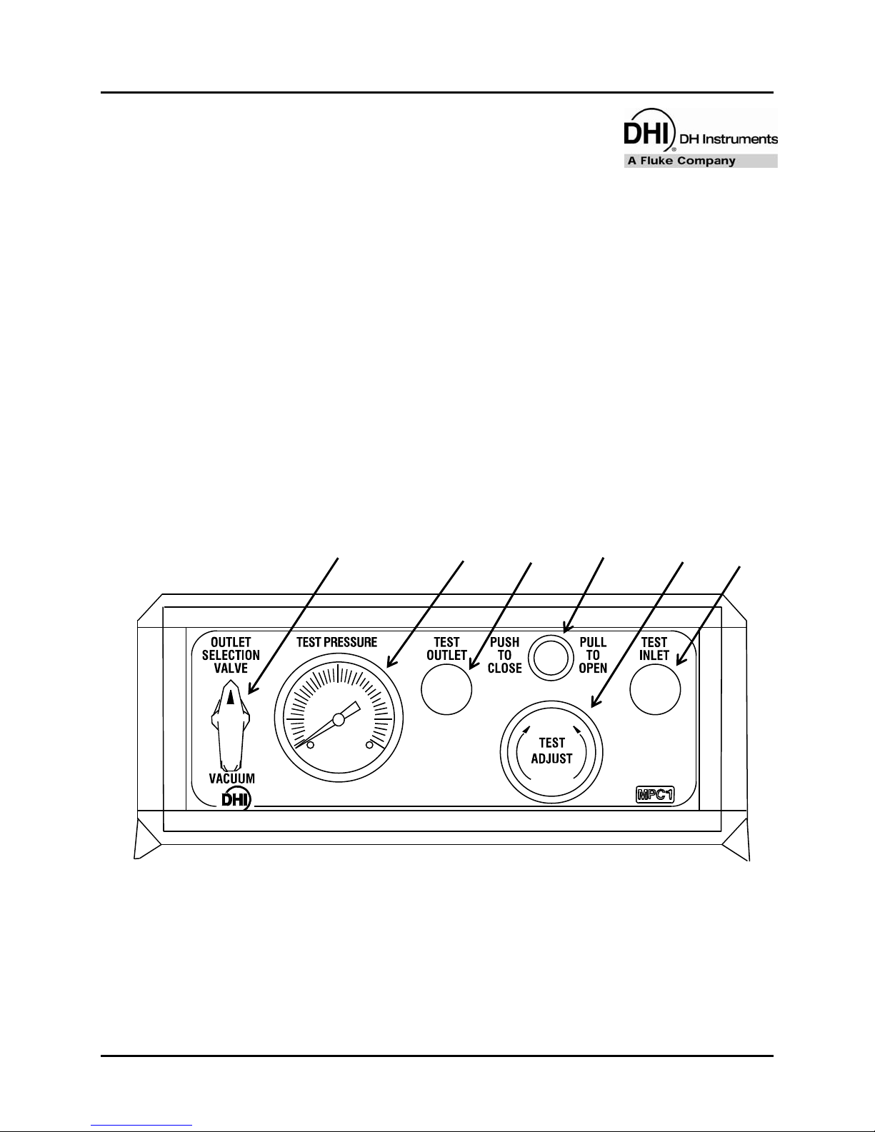
1.2 LOCATION OF THE COMPONENTS
6 3
1. Inlet Valve
2. Variable Volume
3. Equalization Valve
4. Outlet Valve
5. Pressure Gauge (1 000 or 3 000 psi)
6. Outlet Selection Valve
5
4 1
2
Page 1 © 2001 - 2007 DH Instruments, a Fluke Company
Figure 1. Front Panel

MPC1-1000 and MPC1-3000 User’s Manual
2
4
1 3
1. Gas Supply Connection
2. Test Connection
3. Vent Connection
4. Vacuum Connection
1.3 SPECIFICATIONS
Pressure Range: MPC1-1000: Vacuum to 1 000 psi (7 MPa)
Pressure Supply: Equal to or greater than the maximum pressure desired
Pressure Connections: 1/8 in. NPT Female (Supply, Test, Vent, Vacuum)
Dimensions: 320 mm x 172 mm x 370 mm (WxHxD)
Weight: 5.65 kg (12.5 lbs.)
Due to the policy of continual product improvement all specifications are subject to change
without notice.
Figure 2. Back Panel
MPC1-3000: Vacuum to 3 000 psi (21 MPa)
MPC1-1000: 1 200 psi (8 MPa) (maximum supply)
MPC1-3000: 3 200 psi (22 MPa) (maximum supply)
(12.6 in. x 6.8 in. x 14.6 in.)
© 2001 - 2007 DH Instruments, a Fluke Company Page 2

MPC1-1000 and MPC1-3000 User’s Manual
2. INSTALLATION
2.1 UNPACKING AND INSPECTION
The MPC1 is delivered with the inlet valve closed, exhaust valve open and the variable volume (VV)
fully screwed in. Cap plugs are pushed into all rear panel pressure connections.
2.2 SITE REQUIREMENTS
• Gas supply up to maximum amount for model used
• Vacuum source is necessary
2.3 INITIAL SETUP
The MPC1 should be connected to a suitable source of clean, dry, non-corrosive gas using a
1/8 in. NPT male connector to supply (1) on the rear panel. Using the same type connector, hook up
the test system to (2), vacuum source to (4), and any external venting tubing to (3) required to the
corresponding connections on the rear panel. See
The front feet can be folded out to tilt the unit up if desired.
Figure 2.
Page 3 © 2001 - 2007 DH Instruments, a Fluke Company

MPC1-1000 and MPC1-3000 User’s Manual
N
N
OOTTEES
S
© 2001 - 2007 DH Instruments, a Fluke Company Page 4

MPC1-1000 and MPC1-3000 User’s Manual
3. OPERATION
3.1 GENERAL OPERATING PRINCIPLES AND INFORMATION
3.1.1 MPC1
This instrument manually controls pressures from vacuum to 1 000 psi (7 MPa) (MPC1-1000)
or vacuum to 3 000 psi (21 MPa) (MPC1-3000) through the use of valves, a variable volume
(VV) pump and a pressure gauge. Fittings for an outside source of pressure and vacuum are
located on the back panel as are a test connection and vent port. When pressures
(both positive and negative) are needed that are beyond the ability of the VV to generate
by itself, an outside supply of pressure and/or vacuum is required.
The test inlet valve is plumbed directly to the test connection and the high pressure chamber
of the VV. Opening this valve regardless of the position of the equalization valve will result in
an increase of pressure in the test system when pressure is applied to the valve. THIS MAY
RESULT IN AN OVER PRESSURE CONDITION OF THE TEST INSTRUMENT. PLEASE USE
CAUTION WHEN OPERATING THE TEST INLET VALVE.
3.1.2 VALVES
Two types of valves (needle and ball) are used in the MPC1. Two needle valves are used to
control large changes between pressures. A ball valve is used to select between a vacuum
source or an atmospheric reference (vent).
Page 5 © 2001 - 2007 DH Instruments, a Fluke Company

MPC1-1000 and MPC1-3000 User’s Manual
3.1.3 VARIABLE VOLUME (VV)
This is a vessel whose internal volume may be changed by rotating a knob that moves an
internal piston. Attached to the top of the VV is a push/pull equalize valve that is designed to
isolate the low and high sides of the piston, provide protection to the unit itself, and ensure
ease of operation.
The VV is used to adjust the pressure (and/or piston position when used with a piston gauge)
by rotating the knob in the proper direction when the equalization valve is closed.
Before using the test inlet or test outlet valve, open the equalization valve. To open the
equalization valve, pull it outward; to close, push it inward.
When using the VV, it is useful to put its piston in the optimum position based on the intent
of use. Under most operating conditions, the piston is placed in its mid-stroke position (about
16 rotations of the knob from either stop). This will allow for equal movement, forward and
backward, of the piston. When a maximum increase or decrease of pressure is required,
especially at low pressures, place the VV knob at the stop limit (either clockwise for
maximum vacuum or counter-clockwise for maximum pressure).
The VV is designed to operate with a maximum differential pressure of 150 psi (1 MPa)
across the piston. When differential pressures exceed 150 psi (1 MPa), the equalization
valve will automatically open reducing the differential pressure to zero. This is a safety
feature intended to prevent damage to the VV. The value of 150 psi (1 MPa) is factory set
and cannot be changed.
3.1.4 PRESSURE GAUGE
There is a zero to 1 000 psi (7 MPa) or zero to 3 000 psi (21 MPa) dial gauge connected to
the test pressure circuit which has a dual function.
• As a safety device since it is important for the operator to know the value of system
pressure at all times
• As a means for the operator to properly control pressure changes
3.2 SETTING ZERO GAUGE PRESSURE (VENTED)
n Close test inlet valve (1).
o Place outlet selection valve (6) to VENT position.
p Open test outlet valve (4).
q Open pressure equalization valve (3) (pull valve outward).
© 2001 - 2007 DH Instruments, a Fluke Company Page 6

MPC1-1000 and MPC1-3000 User’s Manual
3.3 SETTING POSITIVE GAUGE PRESSURE (ABOVE ATMOSPHERE)
All of the following procedures instruct the operator to open the equalization valve prior to opening
the test inlet and outlet valves. THIS IS A SAFETY PRECAUTION.
It is possible to adjust the pressure in the test circuit using the test inlet valve without opening the
equalization valve. However, this should be done ONLY WHEN THE OPERATION OF THE
SYSTEM AND THE CONSEQUENCES ARE UNDERSTOOD BY THE OPERATOR. Refer to
Sections
3.1, 6.1 and 6.2 for more information.
3.3.1 INCREASING PRESSURE
n Place outlet selection valve (6) to VENT position.
o Close test outlet valve (4).
For small pressure changes, it may be possible to reach the desired pressure using the VV
only, proceed to Step s below.
p Open pressure equalization valve (3) (pull valve outward).
OPENING THIS VALVE MAY RESULT IN A SUDDEN CHANGE IN THE TEST PRESSURE.
Ensure conditions are such that this either does not happen or that its effects
are inconsequential.
q Place VV piston (2) at appropriate position, see Section 3.1.3.
r Open test inlet valve (1) until the approximate desired pressure is reached. Care should
be taken not to overrange the test.
s Close equalization valve (push valve inward).
t Adjust VV knob until desired pressure is obtained (or until the piston floats when
connected to a piston gauge).
Maximum differential pressure across the VV piston is 150 psi (1 MPa). Pressures above
150 psi (1 MPa) will automatically open the equalization valve
u To continue increasing pressures, repeat Step p or t shown above.
Page 7 © 2001 - 2007 DH Instruments, a Fluke Company

MPC1-1000 and MPC1-3000 User’s Manual
3.3.2 DECREASING PRESSURE
For small pressure changes, it may be possible to reach the desired pressure using the VV
only, proceed to Step r below.
n Open pressure equalization valve (3) (pull valve outward).
OPENING THIS VALVE MAY RESULT IN A SUDDEN CHANGE IN THE TEST PRESSURE.
Ensure conditions are such that this either does not happen or that its effects
are inconsequential.
o Place VV piston (2) at appropriate position, see Section 3.1.3.
p Open test outlet valve (4) until the approximate desired pressure is reached.
q Close equalization valve (push valve inward).
r Adjust VV knob until desired pressure is obtained (or until the piston floats when
connected to a piston gauge).
s To continue decreasing pressures, repeat Step n or p shown above.
© 2001 - 2007 DH Instruments, a Fluke Company Page 8

MPC1-1000 and MPC1-3000 User’s Manual
3.4 SETTING NEGATIVE GAUGE PRESSURE (BELOW ATMOSPHERE)
3.4.1 DECREASING PRESSURE
n Close test outlet valve (4).
o Rotate outlet selector valve (6) to vacuum position.
For small pressure changes, it may be possible to reach the desired pressure using the VV
only, proceed to Step p below.
p Open pressure equalization valve (3) (pull valve outward).
OPENING THIS VALVE MAY RESULT IN A SUDDEN CHANGE IN THE TEST PRESSURE.
Ensure conditions are such that this either does not happen or that its effects
are inconsequential.
q Place VV piston (2) at appropriate position, see Section 3.1.3.
r With a vacuum source connected to the vacuum port, open test outlet valve until the
approximate desired pressure is reached.
s Close equalization valve (push valve inward).
t Adjust VV knob until desired pressure is obtained (or until the piston floats when
connected to a piston gauge).
u To continue decreasing pressures, repeat Step p or t shown above.
Page 9 © 2001 - 2007 DH Instruments, a Fluke Company
MPC1-1000 and MPC1-3000 User’s Manual
3.4.2 INCREASING PRESSURE
n Close test outlet valve (4).
o Rotate outlet selector valve (6) to vent position.
For small pressure changes, it may be possible to reach the desired pressure using the VV
only, proceed to Step r below.
p Open pressure equalization valve (3) (pull valve outward).
OPENING THIS VALVE MAY RESULT IN A SUDDEN CHANGE IN THE TEST PRESSURE.
Ensure conditions are such that this either does not happen or that its effects
are inconsequential.
q Place VV piston (2) at appropriate position, see Section 3.1.3.
r Open test outlet valve until the approximate desired pressure is reached.
s Close equalization valve (push valve inward).
t Adjust VV knob until desired pressure is obtained (or until the piston floats).
u To continue increasing pressures, repeat Step p or t shown above.
3.5 SETTING ABSOLUTE PRESSURE
3.5.1 INCREASING PRESSURE
n Close test outlet valve (4).
o Place outlet selection valve (6) to vacuum position.
p Set pressure below atmosphere (if pressures below atmosphere are not required go to
next step).
q Open pressure equalization valve (3) (pull valve outward).
r Place VV piston (2) at appropriate position, see Section 3.1.3.
s Open test outlet valve until the approximate desired pressure is reached.
t Close equalization valve (push valve inward).
u Adjust VV knob until desired pressure is obtained (or until the piston floats when
connected to a piston gauge).
© 2001 - 2007 DH Instruments, a Fluke Company Page 10

MPC1-1000 and MPC1-3000 User’s Manual
v For additional pressures below atmosphere go to Step q.
For small pressure changes, it may be possible to reach the desired pressure using the VV
only, proceed to Step .
w Open pressure equalization valve (pull valve outward).
OPENING THIS VALVE MAY RESULT IN A SUDDEN CHANGE IN THE TEST PRESSURE.
Ensure conditions are such that this either does not happen or that its effects
are inconsequential.
Place VV piston at appropriate position, see Section 3.1.3.
Open test inlet valve (1) until the approximate desired pressure is reached.
Care should be taken not to overrange the test.
Close equalization valve (push valve inward).
Adjust VV knob until desired pressure is obtained (or until the piston floats when
connected to a piston gauge).
Maximum differential pressure across the VV piston is 150 psi (1 MPa). Pressures above
150 psi (1 MPa) will automatically open the equalization valve.
To continue increasing pressures, repeat Step w.
3.5.2 DECREASING PRESSURE
For small pressure changes, it may be possible to reach the desired pressure using the VV
only, see Step r below.
n Open pressure equalization valve (3) (pull valve outward).
OPENING THIS VALVE MAY RESULT IN A SUDDEN CHANGE IN THE TEST PRESSURE.
Ensure conditions are such that this either does not happen or that its effects
are inconsequential
o Place VV piston (2) at appropriate position, see Section 3.1.3.
p Open test outlet valve (4) until the approximate desired pressure is reached.
q Close equalization valve (push valve inward).
r Adjust VV knob until desired pressure is obtained (or until the piston floats when
connected to a piston gauge).
s To continue decreasing pressures, repeat Step p.
Page 11 © 2001 - 2007 DH Instruments, a Fluke Company

MPC1-1000 and MPC1-3000 User’s Manual
N
N
OOTTEES
S
© 2001 - 2007 DH Instruments, a Fluke Company Page 12

MPC1-1000 and MPC1-3000 User’s Manual
4. MAINTENANCE AND
ADJUSTMENTS
No special maintenance or adjustments are required for the MPC1.
Page 13 © 2001 - 2007 DH Instruments, a Fluke Company

MPC1-1000 and MPC1-3000 User’s Manual
N
OOTTEESS
N
© 2001 - 2007 DH Instruments, a Fluke Company Page 14

MPC1-1000 and MPC1-3000 User’s Manual
5. TROUBLESHOOTING
5.1 GENERAL INFORMATION
The MPC1 consists of three valves: a variable volume (VV), a pressure gauge and various tubing
and fittings. Several predictable problems can arise while using the instrument and are addressed in
this section. It is recommended that whomever performs the following troubleshooting procedures
become familiar with the system schematic (see Section
Section
For problems not covered in this section, or direct technical assistance and/or for ordering information
on replacement components, please contact the Technical Service Department.
6.2).
6.1) including the VV description (see
5.2 LEAKS
Pressure leaks are the most common problem found in pressure handling equipment. Normally, the
first step is to determine if the leak is within the MPC1 or if it is outside of the unit.
To determine if the leak is within the MPC1, you must disconnect the unit at the test connection and
plug it. Establish similar conditions under which the leak was observed and determine if the leak is
still present. For small leaks, it may be necessary to install an appropriate pressure sensing device
at the test port, user discretion required. In some cases, it is useful to perform simple leak checks
on the most common outside sources before disconnecting the test system.
Leaks inside the MPC1 are unusual unless there has been some disassembly.
Because of the close fitting components and short tubing runs, some users may find it beneficial to
return the MPC1 to DHI for repair rather than perform the troubleshooting and repair themselves.
To do so, contact DHI Technical Service.
More than one leak can exist in a system so fixing one does not guarantee a leak tight system.
Therefore, continue executing the troubleshooting procedures until all leaks are located
and corrected. Since a troubleshooting guide that will cover every conceivable possibility is
impractical, the source of your leak may not be shown here.
Page 15 © 2001 - 2007 DH Instruments, a Fluke Company

MPC1-1000 and MPC1-3000 User’s Manual
There are four possible leak conditions:
• A leak causing a pressure increase when system pressure is above atmosphere
• A leak causing a pressure decrease when system pressure is above atmosphere
• A leak causing a pressure increase when system pressure is below atmosphere
• A leak causing a pressure decrease when system pressure is below atmosphere
A common reaction to a system leak is to close a particular valve more tightly. Although a valve may
not have been completely closed, care should be used when attempting to do so.
Repeatedly overtightening a valve may result in premature failure.
If a procedure requires you to tighten a leaky fitting, there are two precautions that need to
be observed. First, never tighten a fitting while it is under pressure. If pressure is in the system and
the fitting should fail while tightening it, there is a possibility of injury. Second, do not overtorque the
compression type fittings that are inside the MPC1. Overtorquing these fittings will damage them
requiring their replacement.
5.2.1 PRESSURE INCREASE LEAK (ABOVE ATMOSPHERE)
Only three conditions within the MPC1 can cause this type of leak:
1. A damaged or improperly closed test inlet valve (1) when a pressure source is
connected.
2. A leaking VV piston O-ring.
3. A leaking or improperly closed equalization valve (3).
1. is the most probable cause. Check if the valve is properly closed, use caution not to
overtorque the valve. If an upward leak is still present, remove the source pressure from the
supply connection and observe conditions. If pressure begins to drop, use a leak detection
liquid at the supply fitting. If bubbles are present, replace or repair the test inlet valve.
2. and 3. can only cause an upward leak if the pressure in the front chamber of the VV is
above that in the test circuit. Generate a pressure in the front chamber by closing the
equalization valve (push in) and rotating the VV knob counter-clockwise.
The pressure in the test circuit will decrease. Wait for pressure to stabilize. If pressure rises,
check to see if the equalization valve is properly closed. If pressure continues to increase,
open equalization valve. Wait for pressure to stabilize. If pressure stops increasing,
have VV serviced.
© 2001 - 2007 DH Instruments, a Fluke Company Page 16

MPC1-1000 and MPC1-3000 User’s Manual
5.2.2 PRESSURE DECREASE LEAK (ABOVE ATMOSPHERE)
This is the most common leak condition and can be caused by a variety of components
and fittings. The first step is to isolate the leak to a particular area within the MPC1.
Establish the conditions under which the leak occurs. After doing so, close the test
outlet valve, position the outlet selection valve to VENT and open the equalization valve
(pull out). Wait for the pressure to stabilize (about 1 to 5 minutes). Close the equalization
valve (push in). If the indication of the leak is gone, see Steps n through p below. If the
leak is still present, go to Section
n If the pressure drop is gone, the leak is downstream of the equalization valve stem seal.
Possible sources include the low pressure side of the VV, low pressure side of the
equalization valve, the test outlet valve and the fittings between the two valves.
To check the test outlet valve for a leak past the seat, look for gas at the vent fitting on
the unit's back panel using a leak detection fluid. If a leak is present, the test outlet valve
is not properly closed or is damaged. Tighten, repair or replace the valve as needed.
o If the leak is not found at the vent port, check the fittings between the equalization valve
and the outlet valve. Remove the top cover of the MPC1 and check the appropriate
fittings using a leak detection fluid. If a leak is present, carefully tighten or replace the
leaky fitting(s). Refer to Section
4.
5.2 for information about tightening a leaky fitting.
p If the leak is not present at the fittings, it is most likely in the VV. To confirm that the leak
is in the VV, remove it from the MPC1 and connect all tubing together. Repeat leak
check on the MPC1. If leak is gone, the VV needs to be repaired.
q Most leaks are located in either the VV, gauge, filter and/or in the connecting tubing
including the test inlet and equalization valve. It is also possible, though unlikely, for the
leak to be in the test inlet valve. This can only happen if the supply pressure is below the
test pressure. To check, reduce the test pressure to below the supply pressure. If the
leak is gone or if the leak reverses direction, then the problem is in the test inlet valve.
Tighten, repair or replace the valve as needed.
r Remove the top cover. Check all the fittings within the suspected circuit using a leak
detection fluid. If a leak is present, carefully tighten or replace the leaky fitting(s).
Refer to Section
5.2 for information about tightening a leaky fitting.
If no leaks are found, depressurize the system and disconnect the gauge tube at the tee
located near the test port and plug the tee (refer to Section
6.1). Repeat the leak check.
If the leak is gone, the leak is in the gauge or the disconnected fitting. Replace the fitting
and/or repair or replace the gauge.
If the leak is still present, depressurize the system and remove the VV. Connect the test inlet
valve to the tubing that was connected to the rear of the VV. Repeat the leak check. If the
leak is gone, the leak is in the VV or the disconnected fittings. Replace the fittings and/or
repair the VV.
The above steps have resulted in the checking of all items within the MPC1 that could cause
a leak. If you have not located the leak, repeat the steps or contact DHI Technical Service
for additional assistance.
Page 17 © 2001 - 2007 DH Instruments, a Fluke Company

MPC1-1000 and MPC1-3000 User’s Manual
5.2.3 PRESSURE INCREASE LEAK (BELOW ATMOSPHERE)
This type of leak is similar to Section 5.2.2 and can be caused by the same components
and fittings. However, it is much more difficult to locate since it is not possible to use leak
detection fluid. It is often useful to pressurize the system above atmosphere and find the leak
using the procedures outlined in Section
pressure conditions. However, sometimes a leak under vacuum conditions does not exist
under positive pressure conditions.
If the leak cannot be found with a positive pressure, it is recommended the MPC1 be
returned to DHI for repair. If it cannot be returned, proceed as outlined below.
First, isolate the leak to a particular area within the MPC1. Establish the conditions under
which the leak occurs. Then close the test outlet valve, position the outlet selection valve to
VACUUM and open the equalization valve (pull out). Wait for the pressure to stabilize (about
1 to 2 minutes). Close the equalization valve (push in). If the leak is gone, go to Step n.
If the leak is still present, go to Step o.
n If the pressure drop is gone, the leak is between the equalization valve stem seal and the
test outlet valve. Possible sources include the low pressure side of the VV, low pressure
side of the equalization valve and/or the fittings between the two valves.
5.2.2 since a vacuum leak can often be found under
Remove the top cover. Remove the connecting tube between the equalization valve and
the test outlet valve. Inspect the fittings and tube ends for damage. Replace any
damaged parts and reassemble. Check for leaks. If the leak is still present, return the
MPC1 for repair.
o Most leaks are located in either the VV, gauge, filter and/or in the connecting tubing
including between the test inlet and equalization valve. Remove the top cover.
Disconnect the gauge tube at the tee located near the test port and plug the tee (refer to
Section
6.1). Repeat the leak check. If the leak is gone, the leak is in the gauge or the
disconnected fitting. Replace the fitting and/or repair or replace the gauge.
Check all the fittings within the suspected circuit by disconnecting and inspecting them.
Replace any damaged fittings. Reassemble and leak check. If the leak is still present,
return the MPC1 to DHI Technical Service for repair.
© 2001 - 2007 DH Instruments, a Fluke Company Page 18

MPC1-1000 and MPC1-3000 User’s Manual
5.2.4 PRESSURE DECREASE LEAK (BELOW ATMOSPHERE)
Only three conditions within the MPC1 can cause this type of leak:
1. A damaged or improperly closed test outlet valve when a vacuum source is connected
and the outlet selection valve is in the vacuum position.
2. A leaking VV piston O-ring.
3. A leaking or improperly closed equalization valve.
1. is the most probable cause. Check if the valve is properly closed; use caution not to
overtorque the valve. If an upward leak is still present, position the outlet selection valve
to OFF. If the leak stops, replace or repair the test outlet valve.
2. and 3. can only cause a leak of this type if the pressure in the front chamber of the VV is
below that in the test circuit. Reduce the pressure in the front chamber by closing the
equalization valve (push in) and rotate the VV knob clockwise.
The pressure in the test circuit will increase. Wait for pressure to stabilize. If pressure
begins to drop, check to see if the equalization valve is properly closed. If pressure continues
to drop, open equalization valve. Wait for pressure to stabilize. If pressure leak stops,
have VV serviced.
5.3 TEST PRESSURE WILL NOT CHANGE
There are three components involved in changing the pressure:
• Test Inlet Valve (1)
• Variable Volume (2)
• Test Outlet Valve (4) (in conjunction with the Outlet Selection Valve (6))
The MPC1 uses very small inside diameter control tubes. The purpose of the filters is to protect these
tubes from contamination. Do NOT operate the MPC1 without an active filter element of less than a
0.5 micron rating.
Page 19 © 2001 - 2007 DH Instruments, a Fluke Company

MPC1-1000 and MPC1-3000 User’s Manual
5.3.1 TEST INLET VALVE
Two situations can cause a failure to change pressure when using the test inlet valve:
1. A problem with the supply pressure.
2. A plugged filter.
Check the supply and ensure that a gas supply actually exists at the supply port and the
supply pressure is adequate to achieve maximum pressure needs. If the supply is OK, check
the filter by removing the top cover and then removing the filter from the supply line. If the
filter is plugged, disassemble and clean or replace the filter.
5.3.2 VARIABLE VOLUME (VV)
While using the VV to generate pressures it may appear under certain conditions to not be
working when in fact it is. For example, when the system is at low pressure (typically below
20 psia) and working into a large volume. This is due to the compressibility of gases at low
pressures which worsens as pressures decrease and volumes increase. Prevent this
situation when evaluating the performance of the VV.
If pressure cannot be changed through the use of the VV, the problem is with the equalization
valve, the VV piston O-ring or the filter connected to the VV rear plate. Confirm that the
equalization valve is closed (pushed in).
The VV cannot change the pressure when the equalization valve is open. If pressures still
cannot be changed, remove the top panel and the filter. Check the filter for a plugged
condition, clean or replace as needed. If the VV still cannot change the test pressure, have
it serviced.
5.3.3 TEST OUTLET VALVE
Three problems can cause the failure of the test outlet valve to change pressures:
• An incorrectly positioned outlet selection valve
• A closed equalization valve
• A plugged filter
Ensure the outlet selection valve is in the proper position for the work being done (either
VENT or VACUUM). If the valve is in the OFF position, select VENT or VACUUM.
Ensure the equalization valve is open (pull out). If the valve was closed, be aware that a
sudden change of pressure at the test can occur when the valve is opened.
To check if the filter is plugged, select the VACUUM position with the outlet selection valve.
If the system begins to operate correctly the filter is most likely plugged; clean or replace
as needed.
© 2001 - 2007 DH Instruments, a Fluke Company Page 20

MPC1-1000 and MPC1-3000 User’s Manual
5.4 PRESSURE CHANGES SLOWLY OR SLUGGISHLY
This is caused by a partially plugged filter or a large connected volume. Remove and clean or
replace the filter as needed.
The MPC1 uses very small inside diameter control tubes. The purpose of the filters is to protect these
tubes from contamination. Do NOT operate the MPC1 without the active filter elements of less than a
0.5 micron rating.
Pressure changes can be slow if a large external volume is connected to a MPC1. This condition is
compounded by a low supply pressure. If the pressure changes are too slow due to a large external
volume, reduce the volume.
Page 21 © 2001 - 2007 DH Instruments, a Fluke Company

MPC1-1000 and MPC1-3000 User’s Manual
N
OOTTEESS
N
© 2001 - 2007 DH Instruments, a Fluke Company Page 22

MPC1-1000 and MPC1-3000 User’s Manual
6. ANNEXES
6.1 PNEUMATIC SCHEMATIC
Page 23 © 2001 - 2007 DH Instruments, a Fluke Company

MPC1-1000 and MPC1-3000 User’s Manual
6.2 VARIABLE VOLUME INFORMATION
© 2001 - 2007 DH Instruments, a Fluke Company Page 24

MPC1-1000 and MPC1-3000 User’s Manual
6.2.1 VARIABLE VOLUME SPECIFICATIONS
Table 1. Variable Volume Specifications
Range Vacuum to 1 000 psi (7 MPa) Vacuum to 3 000 psi (21 MPa)
Proof 3 000 psi (21 MPa) 6 000 psi (42 MPa)
Burst 6 000 psi min (42 MPa) 12 000 psi min (84 MPa)
Total Volume 3.5 cu in. (57.5 cc) 2.5 cu in. (41 cc)
Revolutions for Total Volume 31 61
MPC1-1000 MPC1-3000
Page 25 © 2001 - 2007 DH Instruments, a Fluke Company

MPC1-1000 and MPC1-3000 User’s Manual
N
OOTTEESS
N
© 2001 - 2007 DH Instruments, a Fluke Company Page 26
 Loading...