

DH Instruments MOLSTIC-S SUPPLY ONLY PLATFORM 1-4 IN. AND 1-2 IN, molstic-S, 401876, 401877 Installation Sheet
Page 1

The 1/4 in. and 1/2 in. supply only molstic-S platforms,
P/N 401876 and 401877, provide inlet gas pressure
regulation to either the Device Under Test (DUT) or the
downstream molstic-S mounting systems. They are
used to control the pressure supplied to an upstream
DUT, or to adjust the flow rate through the system
while calibrating a downstream DUT.
High pressure gases are potentially hazardous.
Energy stored in these gases can be released
unexpectedly and with extreme force. High
pressure systems should be assembled and
operated only by personnel who have been
instructed in proper safety practices.
molstic-S™ Supply Only Platform
1/4 in. and 1/2 in.
P/Ns 401876 and 401877
Installation Sheet
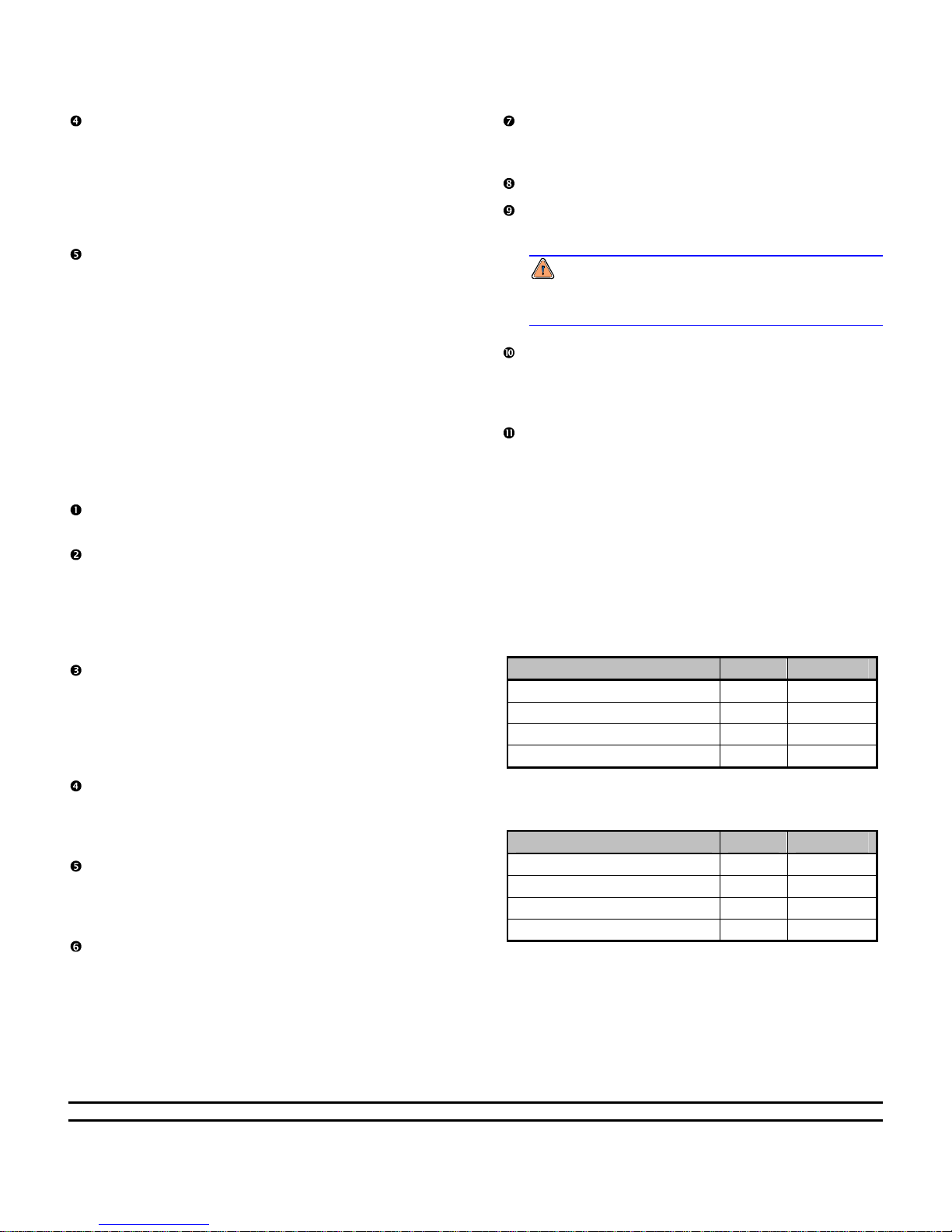
Figure 2 1/2 in. Supply Only molstic-S
1. Quick connect adaptor
(includes stem with 1/2 in. SWG - not shown)
2. Pressure reducing regulator
3. Flow metering/shut-off valve
4. Outlet adaptor, 1/2 in. tube x 1/2 in. male VCR
OPERATION OF SUPPLY ONLY MOLSTIC-S
Set regulator outlet pressure to minimum.
Rotate the knob of the pressure reducing regulator
in the counterclockwise direction until the spring
force of the diaphragm is relieved. Insure that the
shut-off valve is in the closed position.
Be sure that the molstic-S supply only
platform shut-off valve is closed prior to
connecting the quick connect stem to the
Figure 1 1/4 in. Supply Only molstic-S
1. Quick connect adaptor
(includes stem with 1/4 in. SWG - not shown)
2. Pressure reducing regulator
3. Flow metering/shut-off valve
4. Outlet adaptor, 1/4 in. tube x 1/4 in. male VCR
Connect the gas supply.
Connect the gas supply to the quick connect stem
(either 1/4 in. or 1/2 in. tube). The gas supply
pressure should not exceed 1.7 MPa (250 psig).
Insert the stem into the quick connect body.
Connect the outlet of the supply only platform to
either the DUT or the inlet of the molstic-S.
quick connect body (located on the inlet side
of the regulator).
Page 2
The outlet pressure of the pressure reducing
regulator is controlled by adjusting the position of
the control knob. Rotating the knob clockwise
raises the outlet pressure. Counterclockwise
rotation, coupled with venting of the downstream
side of the regulator plumbing, lowers the outlet
pressure.
Make final adjustments of control pressure in the
direction of increasing pressure in order to obtain
the most accurate and stable set point.
INSTALLATION OF THE PRESSURE
REDUCING REGULATOR ONTO
MOLSTIC-S PLATFORM
The pressure reducing regulator can be removed from
the supply only molstic-S platform and mounted onto
the molstic-S platform. Use the following procedure
to install the pressure reducing regulator onto the
molstic-S platform:
Disconnect the gas supply from the supply only
platform and vent any residual pressure.
Using a pair of properly sized open-end wrenches
loosen the VCR
side of the VCR double male union between the
regulator and the flow control/shut-off valve.
Leave the double male union assembled to the
regulator.
Using the proper size hex wrench, remove and
retain the socket head cap screws, washers, and
nut plate that mount the regulator and its bracket
to the supply only molstic-S platform, along with
the VCR double male union. Do not disassemble
the bracket from the regulator.
Using a pair of properly sized wrenches remove
the VCR x tube adaptor on the inlet end of the
molstic-S, remove the VCR gasket and discard.
Retain the adaptor for future use.
Place a new VCR gasket (P/N 102183 for 1/4 in. or
102923 for 1/2 in.) securely against the sealing
surface inside the female VCR swivel nut of the
molstic-S inlet fitting.
Place the regulator with its bracket on top of the
molstic-S platform.
®
swivel nut on the downstream
Align the regulator’s male VCR fitting with the
mating female swivel nut and thread the nut onto
the fitting.
Tighten the female nut finger-tight.
Hold male body stationary with a backup wrench.
Tighten the female nut 1/8 turn past finger-tight.
Over-tightening will damage the sealing
beads and possibly cause system leakage.
Do not re-use VCR gaskets.
Place the flat side of the 60 mm nut plate under
the molstic-S platform. Align it with the holes in the
platform and the regulator bracket. Hold it in
place.
Thread the socket head cap screws through the
regulator bracket and tighten securely into the nut
plate.
ACCESSORIES INCLUDED WITH THE
SUPPLY ONLY MOLSTIC-S SHIPMENT
The following accessories are included in the supply
only molstic-S shipment:
P/N 401941
1/4 in. Supply Only molstic-S Accessory Kit
DESCRIPTION QTY PART NO.
Gasket, VCR, 1/4 in. 2 102183
O-ring, VCR face seal, 1/4 in. 2 102070
Tubing, 1/4 in. PFA, 50 cm 1 101450-Z
Quick connect stem, 1/4 in. 1 102458
P/N 401949
1/2 in. Supply Only molstic-S Accessory Kit
DESCRIPTION QTY PART NO.
Gasket, VCR, 1/2 in. 2 102923
O-ring, VCR face seal, 1/2 in. 2 102912
Tubing, 1/2 in. PFA, 50 cm 1 103227-Z
Quick connect stem, 1/2 in. 1 103235
molbloc and molbloc-S are trademarks, registered and otherwise, of DH Instruments, Inc.
Viton is a registered trademarks of DuPont deNemours Company.
Document 560049a 030108
DH Instruments, Inc.
4765 East Beautiful Lane
Phoenix AZ 85044-5318
USA
VCR is a registered trademark of the Swagelok Company.
Tel 602.431.9100
Fax 602.431.9559
dhi@dhinstruments.com
www.dhinstruments.com
 Loading...