


GB-H-152-70M and GB-H-152-100M
Gas Booster Packages
Operation and Maintenance Manual
© 2008 DH Instruments, a Fluke Company
GB-H-152 GAS BOOSTER PACKAGE OPERATION AND MAINTENANCE MANUAL
This equipment described in this manual is designed and manufactured for the intended purpose of
generating high pressure gas and regulating a high gas pressure output. Certain precautions need to be
followed during installation and operation of this device. Reading and understanding the material is essential
to the safe and correct operation of the unit.
Pressurized equipment is potentially dangerous. The equipment described in this manual generates and
controls very high gas pressures. It should not be operated by anyone who has not thoroughly familiarized
themselves with this manual. Additional training in general and pressure specific safety procedures will help
assure protection from harm or damage to personnel or property. Responsibility for the proper and safe
operation of this instrument rests with the user.
Do not use oxygen. This instrument is not compatible with the use of oxygen. Hydrocarbon elastomers
and lubricants are present.
High pressure liquids and gases are potentially hazardous. Energy stored in these liquids and gases
can be released unexpectedly and with extreme force. High pressure systems should be assembled and
operated only by personnel who have been instructed in proper safety practices.
© 2008 DH Instruments, a Fluke Company All rights reserved.
Information in this document is subject to change without notice. No part of this document may be reproduced or transmitted in any
form or by any means, electronic or mechanical, for any purpose, without the express written permission of DH Instruments, a
Fluke Company 4765 East Beautiful Lane Phoenix AZ 85044-5318 USA.
DH Instruments makes every effort to ensure the accuracy and quality of it’s published materials; however, no warranty, expressed
or implied, is provided. DH Instruments disclaims any responsibility or liability for any direct or indirect damages resulting from the
use of the information in this manual or products described in it. Mention of any product or brand does not constitute an
endorsement by DH Instruments of that product or brand. This manual was originally composed in English and was subsequently
translated into other languages. The fidelity of subsequent translations cannot be guaranteed. In case of conflict between the
English version and another language version, the English version predominates.
DH Instruments, DH , DHI, PPC, PPCH-G, PPC3, RPM4 and CalTool are trademarks, registered and otherwise of DH
Instruments, a Fluke Company..
Swagelok is a registered trademark of the Swagelok Company. Teflon is a registered trademark of the 3M Corporation.
Document No. 550162a
080423
Printed in the USA.
© 2008 DH Instruments, a Fluke Company

TABLE OF CONTENTS
T
AABBLLEE
T
TABLE OF CONTENTS ...............................................................I
TABLES.................................................................................III
FIGURES
ABOUT THIS MANUAL..............................................................V
1. INTRODUCTION ................................................................. 1
1.1 PRODUCT OVERVIEW ...........................................................................................................................1
1.2 LOCATION AND DESCRIPTION OF COMPONENTS............................................................................2
1.3 SYSTEM SCHEMATIC ............................................................................................................................3
1.4 SPECIFICATIONS ...................................................................................................................................4
2. INSTALLATION .................................................................. 5
2.1 UNPACKING AND INSPECTION ............................................................................................................5
2.2 SITE REQUIREMENTS............................................................................................................................6
2.3 INSTALLATION AND SETUP..................................................................................................................7
O
O
................................................................................III
2.3.1 INSTALLATION CONSIDERATIONS............................................................................................................7
2.3.2 INSTALLATION.............................................................................................................................................7
FF
C
OONNTTEENNTTS
C
S
3. OPERATION....................................................................... 9
3.1 GENERAL OPERATING PRINCIPLE AND INFORMATION...................................................................9
3.1.1 PNEUMATICALLY OPERATED GAS BOOSTER PUMP (11)......................................................................9
3.1.2 BOOSTER DRIVE SHUTOFF VALVE (13)..................................................................................................10
3.1.3 ACCUMULATOR (9)....................................................................................................................................10
3.1.4 DRIVE AIR REGULATOR/FILTER (15).......................................................................................................10
3.1.5 HIGH PRESSURE REGULATOR (6)...........................................................................................................10
3.1.6 GAUGES (3, 7, 14).......................................................................................................................................11
3.2 SETTING HIGH PRESSURE OUTPUT EQUAL TO OR LESS THAN THE SUPPLY PRESSURE.......11
3.2.1 INCREASING PRESSURE..........................................................................................................................11
3.2.2 DECREASING PRESSURE.........................................................................................................................11
3.3 SETTING HIGH PRESSURE OUTPUT GREATER THAN SUPPLY PRESSURE ................................12
3.3.1 SETTING BOOSTER DRIVE PRESSURE ..................................................................................................12
3.3.2 INCREASING PRESSURE..........................................................................................................................13
3.3.3 DECREASING PRESSURE.........................................................................................................................13
4. MAINTENANCE AND ADJUSTMENTS .................................. 15
4.1 MAINTENANCE.....................................................................................................................................15
Page i © 2008 DH Instruments, a Fluke Company

GB-H-152 GAS BOOSTER PACKAGE OPERATION AND MAINTENANCE MANUAL
5. TROUBLESHOOTING ........................................................ 17
5.1 GENERAL INFORMATION....................................................................................................................17
5.2 BOOSTER WILL NOT RUN...................................................................................................................17
5.3 BOOSTER RUNS TOO SLOWLY .........................................................................................................17
5.4 PRESSURE GENERATES TOO SLOWLY OR NOT AT ALL...............................................................18
5.5 BOOSTER RUNS CONTINUOUSLY.....................................................................................................18
5.6 CANNOT ACHIEVE PRESSURE...........................................................................................................19
5.7 LEAKS ...................................................................................................................................................19
5.8 GAS CONTINUOUSLY VENTS THROUGH EXHAUST MUFFLER......................................................20
6. WARRANTY STATEMENT .................................................. 21
6.1 WARRANTY STATEMENT....................................................................................................................21
© 2008 DH Instruments, a Fluke Company Page ii

TABLES & FIGURES
T
AABBLLEES
T
Table 1. GB-H-152-70M and GB-H-152-100M Parts List.............................................................................5
Table 2. DHI Authorized Service Providers ...............................................................................................22
F
IIGGUURREES
F
Figure 1. GB-H-152 Top and Side Views .....................................................................................................2
Figure 2. System Schematic.........................................................................................................................3
S
S
Page iii © 2008 DH Instruments, a Fluke Company

GB-H-152 GAS BOOSTER PACKAGE OPERATION AND MAINTENANCE MANUAL
N
N
OOTTEES
S
© 2008 DH Instruments, a Fluke Company Page iv

ABOUT THIS MANUAL
A
BBOOUUTT
A
(CAUTION) is used in throughout the manual to identify user warnings and cautions.
(NOTE) is used throughout the manual to identify operating and applications advice and
additional explanations.
T
T
HHIISS
M
AANNUUAAL
M
L
Manual Conventions
Page v © 2008 DH Instruments, a Fluke Company

GB-H-152 GAS BOOSTER PACKAGE OPERATION AND MAINTENANCE MANUAL
N
N
OOTTEES
S
© 2008 DH Instruments, a Fluke Company Page vi

1. INTRODUCTION
.
11.
I
NNTTRROODDUUCCTTIIOON
I
N
1.1 PRODUCT OVERVIEW
GB-H-152-70M and GB-H-152-100M are gas booster packages intended to be used to provide the gas
pressure supplies required by DHI PPCH-G controller/calibrators for high pressure gas.
Both models include a pneumatically driven, piston type, self-cycling gas booster with regulated output to
provide the PPCH-G high pressure supply. The gas booster boosts a lower pressure usually supplied
from a bottle, to higher pressure. The high pressure gas is stored in an accumulator volume to assure
stable supply to the PPCH-G. GB-H-152-70M has a maximum output pressure of 100 MPa (15 000 psi).
GB-H-152-100M has a maximum output of 120 MPa (18 000 psi).
Both models also include an independent low pressure output to supply the PPCH-G drive air
requirement.
With a GB-H-152 gas booster, all of the PPH-G pressure supply requirements are taken care of in one
simple package requiring only the connection of a test gas source and a drive air supply to power the
booster.
Page 1 © 2008 DH Instruments, a Fluke Company
GB-H-152 GAS BOOSTER PACKAGE OPERATION AND MAINTENANCE MANUAL
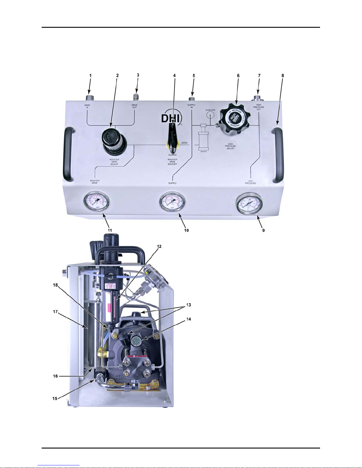
1.2 LOCATION AND DESCRIPTION OF COMPONENTS
1. Drive air supply connection
2. Drive air supply regulator
3. Drive air out connection to PPCH-G DRIVE
(unregulated)
4. Booster drive air shut off valve
(booster ON/OFF)
5. Test gas supply connection
6. High pressure gas output regulator
7. Regulated high pressure gas output
connection
8. Carrying handle (2)
9. High pressure gas output gauge
10. Test gas supply pressure gauge
11. Regulated booster drive pressure gauge
12. Drive air supply filter
13. Filtered breather
14. Drive air exhaust muffler
15. Shuttle valve
16. Accumulator drain plug (not visible)
17. Accumulator
18. Drive air filter bowl drain valve
© 2008 DH Instruments, a Fluke Company Page 2
Figure 1. GB-H-152 Top and Side Views

1. INTRODUCTION
1.3 SYSTEM SCHEMATIC
1. Test gas supply connection
2. Test gas filter
3. Test gas supply pressure gauge
4. Test gas supply connection to booster
5. High pressure gas raw output from booster
6. High pressure gas regulator
7. High pressure regulated gas output gauge
8. Regulated high pressure gas output connection
9. High pressure gas accumulator
Figure 2. System Schematic
10. High pressure gas accumulator drain
11. Gas booster
12. Drive air connection to booster
13. Drive air shut-off valve (booster on/off)
14. Regulated drive air pressure gauge
15. Drive air filter/regulator
16. Drive air supply connection
17. Drive air output for connection to PPCH-G
Page 3 © 2008 DH Instruments, a Fluke Company

GB-H-152 GAS BOOSTER PACKAGE OPERATION AND MAINTENANCE MANUAL
1.4 SPECIFICATIONS
Dimensions
Weight (shipping)
Drive air pressure supply
Range
Test gas pressure supply
Range
Output pressure
GB-H-152-70M
GB-H-152-100M
Operating media
Pressure connections
Drive air supply
Shop drive out
Test gas pressure supply
High pressure gas out
Nominal gas booster piston ratio
High pressure accumulator volume
50 cm (20 in.) H x 57 (22.5 in.) W x 30 (12 in.) D
44.4 kg (98 lb)
0.15 to 1 MPa (20 to 150 psi)
425 to 2 125 slm (15 to 75 scfm)
Flow
4.8 to 40 MPa (700 to 6 000 psi)
140 to 560 slm (5 to 20 scfm)
Flow
0.70 to 100 MPa (400 to 15 000 psi)
0.35 to 120 MPa (200 to 17 400 psi)
air, helium, nitrogen
1/4 in. NPT F
1/4 in. Swage
1/8 in. NPT F
DH500F
(DH500 is a gland and collar type fitting for ¼ in. (6.35 mm)
coned and left hand threaded tube. DH500 is equivalent to AE
F250C, HIP HF4, etc.)
152:1
150 cc (9.2 in.
3
)
Due to a policy of continual product improvement, all specifications are subject to change without notice.
© 2008 DH Instruments, a Fluke Company Page 4
2. INSTALLATION
.
22.
I
NNSSTTAALLLLAATTIIOON
I
N
2.1 UNPACKING AND INSPECTION
GB-H-152-70M and GB-H-152-100M are delivered enclosed in plastic film and secured in place in a
wooden crate. All ports are plugged, the drive air valve is closed and pressure regulators are set to zero.
Remove the instrument from the shipping crate and plastic bag. Take care not to lose or discard the
accessories that are included.
Remove all plastic plugs from the fittings and inspect for damage and contamination.
Inspect for any missing components or accessories using Table 1. Should any items be missing, contact
DHI or you local supplier.
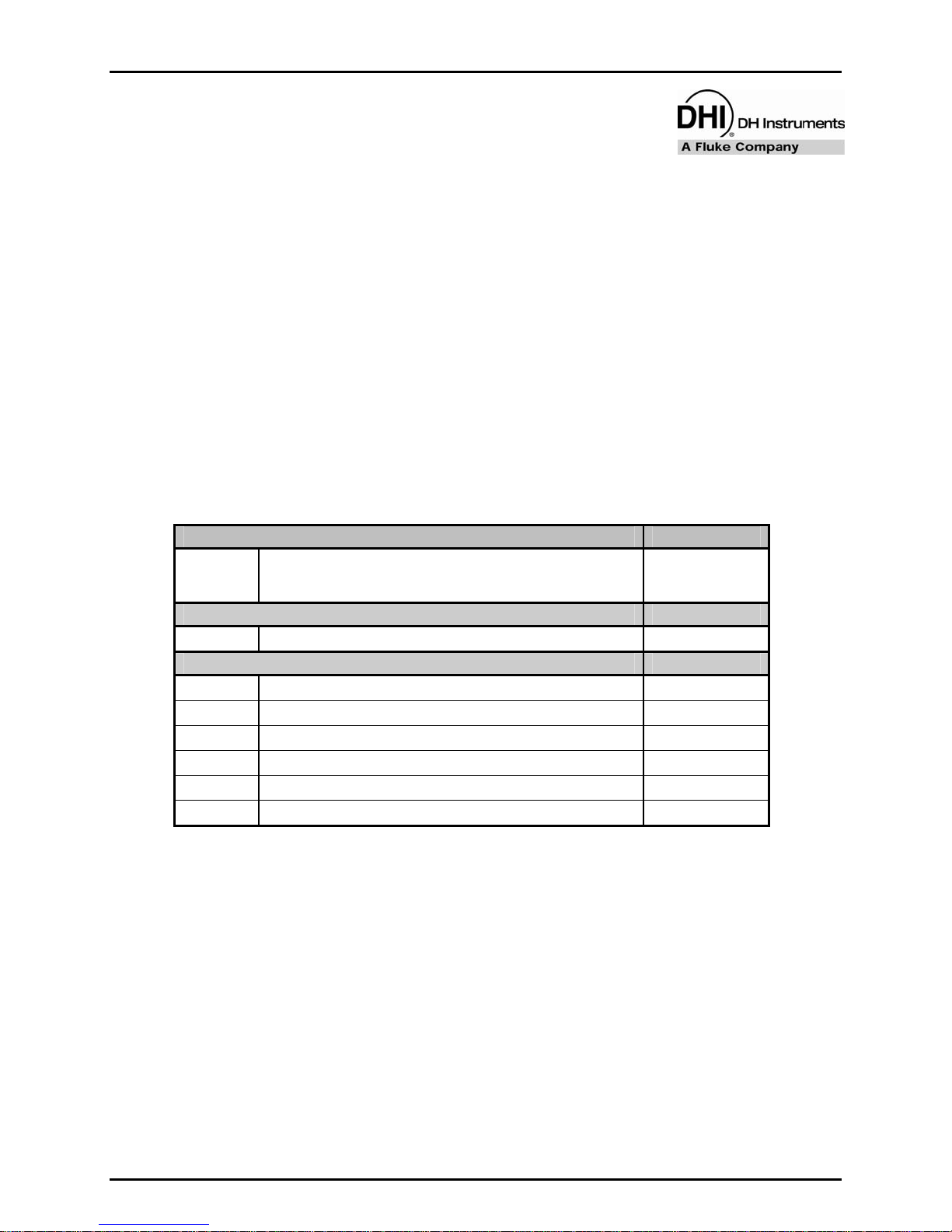
Table 1. GB-H-152-70M and GB-H-152-100M Parts List
DESCRIPTION PART #
1 ea. GB-H-152-70M gas booster package
or
GB-H-152-100M gas booster package
ACCESSORIES:
1 ea. Operation and Maintenance Manual 550162
INTERCONNECTIONS KIT: 402390
1 ea. Tube weld, 1.5 m (60 in.) x 1/8 in. (3 mm) with DH500 tips (coiled) 402506
1 ea. Adaptor, 1/8 in. M x 1/4 in. Swage 102033
200 cm. 1/4 in. PFA tubing 101450-Z
1 ea. Nut, 1/4 in. Swage 100247
1 ea. Ferrule, front, 1/4 in. Swage 100248
1 ea. Ferrule, rear, 1/4 in. Swage 100249
402387
or
402379
Page 5 © 2008 DH Instruments, a Fluke Company

GB-H-152 GAS BOOSTER PACKAGE OPERATION AND MAINTENANCE MANUAL
2.2 SITE REQUIREMENTS
Two sources of compressed gas are required to operate the gas booster package: 1) shop drive air
supply to power the booster; 2) high pressure gas that the booster will compress to higher pressures.
Due to the different flow rate and cleanliness requirements for each of these supplies, they should come
from two separate sources. It is not recommended that hazardous gases be used unless appropriate
precautions are taken.
1) Shop drive air supply:
The shop air drive supply powers the booster and may be used for the PPCH-G DRIVE connection.
The booster high pressure output is approximately 152 times the drive air supply assuming the test
gas supply pressure is high enough.
Shop drive air requirements are:
Pressure:
- For operation up to 50 MPa (7 500 psi): 0.4 MPa (60 psi) minimum
- For operation up to 80 MPa (11 600 psi): 0.55 MPa (80 psi) minimum
- For operation up to 100 MPa (15 000 psi) (maximum of GB-H-152-70M: 0.66 MPa (96 psi) minimum
- For operation up to 120 MPa (17 400 psi) (maximum of GB-H-152-100M: 0.80 MPa (116 psi) minimum
As the booster package includes an accumulator and high pressure regulator, it is preferable to
generate the highest pressure that can be achieved and regulate it down to the appropriate supply pressure
for the PPCH-G range to which the booster is connected. The higher the pressure in the accumulator and
upstream of the high pressure regulator, the greater the reserve of high pressure to assure an stable
supply of pressure to the PPCH-G. Do not exceed 100 MPa (15 000 psi) with GB-H-152-70M or 120 MPa
(18 000 psi) with GB-H-152-100M. To assure pressure is within these limits, do not set booster drive
adjust regulator greater than 0.66 MPa (96 psi) with GB-H-152-70M or 0.80 MPa (116 psi) with
GB-H-152-100M.
Flow rate: 425 slm (15 scfm) minimum
Cleanliness: Not critical, use 60 micron filter
Humidity: 20 to 50 % RH. Do not use dry gas. Do not use hazardous gases.
2) High pressure instrument gas supply:
High pressure instrument gas is boosted by the booster and supplied to the PPCH-G SUPPLY port.
High pressure instrument gas supply requirements are:
Pressure: Minimum booster output pressure/25. Recommended minimum is 4 MPa (600 psi) with
GB-H-152-70M and 5 MPa (750 psi) with GB-H-152-100M Maximum 40 MPa (6 000 psi)
Flow rate: 140 slm (5 scfm) minimum
Gas quality: Use clean, dry, non-corrosive instrument grade gases only. Filtration of 10 micron with a
dew point of -20 to 5 °C is recommended. Inlet gas temperature should be between 10 and 47 C.
© 2008 DH Instruments, a Fluke Company Page 6

2. INSTALLATION
2.3 INSTALLATION AND SETUP
2.3.1 INSTALLATION CONSIDERATIONS
Installation of the GB-H-152 depends on the specific application. For a detailed description
of the theory of operation see Section 3.1. Refer to Section 2.3 before attempting installation.
A variety of factors must be considered when determining
where to locate the GB-H-152.
Factors include, but are not limited to:
• the high pressure being generated and associated safety concerns
• the source of gas supplies (drive air supply and high pressure instrument gas supply)
• noise level
• exhaust of drive air out of the muffler
• vibration during use
• access to the unit for operation of the regulators and valve
• point of use of output pressures
2.3.2 INSTALLATION
To install the GB-H-152, follow the steps below (numerical references refer to Figure 2):
n Place the GB-H-152 in the desired location.
o Close both regulators (2) and (6) by rotating the knobs counter-clockwise until no spring
force is felt.
The drive adjust (2) and high pressure adjust (6) regulators have a stop that prevents
continued counter-clockwise rotation.
The drive adjust regulator (2) has a locking mechanism to prevent accidental adjustment.
To unlock, pull the knob up.
p Close the booster drive shutoff valve (4).
q Connect shop drive air supply to the 1/4 in. NPT F DRIVE IN port using tubing of
appropriate pressure rating.
Maximum input pressure to the booster drive adjust regulator (2) is 1.7 MPa (250 psig).
Pressures above this level may result in a failure that could damage the instrument and/or cause
personal injury. Using connecting tubing rated for working pressures below 1.7 MPa (250 psig) is
not recommended.
r Connect the test gas supply to the 1/8 in. NPT F SUPPLY IN port (6) using tubing of
appropriate pressure rating.
Maximum input pressure to the SUPPLY IN port (5) is 40 MPa (6 000 psig). Pressure above
this level may result in a failure that could damage the instrument and/or cause personal injury.
Page 7 © 2008 DH Instruments, a Fluke Company

GB-H-152 GAS BOOSTER PACKAGE OPERATION AND MAINTENANCE MANUAL
Pressure present at the SUPPLY IN port (5) will be present at the inlet port of the high
pressure adjust regulator (6). To prevent gas pressure from reaching the HIGH PRESSURE OUT
port (7), ensure that the high pressure adjust regulator is closed (backed off).
s If desired, connect the 1/4 in. Swage DRIVE OUT connection (3) to the drive air point of
use with appropriately rated tubing.
If connecting to the PPCH-G DRIVE port, use the hardware provided in the GB-H-152
interconnect kit:
- Install the 1/8 in. M x 1/4 in. Swage adaptor in the PPCH-G DRIVE port.
- Remove the 1/4 in. Swage plug from the GB-H-152 DRIVE OUT port.
- Connect the PPCH-G DRIVE port to the GB-H-152 DRIVE OUT port with the 2 m. of
1/4 in. PFA tubing (cut the tube to a shorter length if desired). Use the supplied
Swage 1/4 in. nut and front and rear ferrules for the DRIVE OUT end of the tube.
Take care to align the ferrules correctly.
If the DRIVE OUT port is not being used, leave it capped.
t Connect the DH500F HIGH PRESSURE OUT port (7) to the high pressure gas point of
use with tubing of appropriate pressure rating (able to handle the maximum pressure that
the booster will generate). Working pressure rating should be at least 100 MPa (15 000)
psig for GB-H-152-70M and 140 MPa (20 000 psig) for GB-H-152-100M.
When using the GB-H-152 with a PPCH-G pressure controller/calibrator use the
hardware provided in the GB-H-152 interconnect kit:
Connect the 1.5 m, 1/8 in. nipple with DH500 tips between the GB-H-152 HIGH
PRESSURE OUT port and the PPCH-G SUPPLY port. The DH500 glands and
collars are delivered installed in the female ports. Remove the orange plastic plug,
slip the gland onto the DH500 tip, install the collar onto the DH500 tip and thread the
gland into the female DH500 fitting. Torque gland to 15 Nm (11 lb ft).
Do not bend tubing with radius less than 50 mm (2 in.) or pressure capacity may be reduced.
Using connecting tubing with a working pressure below the maximum pressure generated by
the booster may result in a failure in the tubing that could cause damage to the instrument
and/or cause personal injury.
u If the shop drive air used to operate the GB-H-152 is to be vented to a location other than
where the booster is being used or to reduce the noise level of the operating booster,
proceed as follows:
Remove the drive air exhaust muffler (14). The drive air exhaust muffler (14) and
booster exhaust port are both 1/2 in. NPT F connected via a 1/2 in. NPT nipple.
Therefore, the fitting available for connection is a 1/2 in. NPT M (when using the
nipple) or female (when not using the nipple).
Connect a hose with an I.D. of at least 13 mm (1/2 in.) and maximum length of 16 m
(50 ft.) to the booster fitting (1/2 in. NPT M or F). A hose length of greater than 16 m
(50 ft) can be used provided the I.D. of the hose is increased.
Connect the loose end of the hose to an appropriate termination point.
© 2008 DH Instruments, a Fluke Company Page 8

3. OPERATION
.
33.
O
PPEERRAATTIIOON
O
N
3.1 GENERAL OPERATING PRINCIPLE AND INFORMATION
Numerical references in this section refer to Figure 2.
The purpose of the GB-H-152 booster package is to provide a regulated high pressure gas output with
enough flow to assure a continuous supply to a high pressure gas controller/calibrator such as PPCH-G
when it is increasing pressure. The system generates high pressure using a pneumatically operated gas
booster pump (11), a drive air regulator and shutoff valve (15, 13) and an accumulator volume (9).
Pressure ports are provided to connect the drive air input (16), test gas input (1) and high pressure output
(8). A drive air output connection (17) is also provided as a convenient way to connect drive air to
another point of use such as the DRIVE port of a PPCH-G pressure controller/calibrator. The system is
contained in one compact unit and is ready to operate once gas supplies are connected and regulators
are properly adjusted.
3.1.1 PNEUMATICALLY OPERATED GAS BOOSTER PUMP (11)
The booster pump is a Pascal press utilizing two pistons connected together on the same
axis having a nominal area ratio of 152:1. The booster is a two-stroke, single stage
reciprocating pump that generates gas pressures 152 times greater than the shop drive air
applied to the pump.
The pump operates automatically, provided drive air is supplied to the drive air regulator (15)
and the regulator is set to at least 140 kPa (20 psig). Operation is continuous until the outlet
pressure is 152 times the drive air pressure. Then the opposing forces within the pump
reach equilibrium and the pump stalls. For example, with the drive air pressure set to 0.6
MPa (90 psig), the pump runs until the instrument gas pressure downstream of the booster
reaches 152 x 0.6 = 91.2 MPa (13 224 psig). Note that the high pressure section of the
pump has a nominal compression ratio of 25:1. Therefore, the pressure generated by the
booster cannot be greater than the test gas supply pressure x 25. If the test gas supply
pressure is not high enough to reach the desired output pressure, the booster will run
continuously but the pressure will not increase.
1. The drive section (low pressure) of the booster consists of a piston, cylinder, air cycling
valve, pilot valve and vent section. This section provides the reciprocating action and
compression force needed to operate the booster and generate the high pressure gas.
Drive air is channeled to the appropriate side of the piston (compression or suction
stroke) by the air cycling valve. When the piston reaches full stroke, a pilot valve is
mechanically activated causing the air cycling valve to change position. Shop drive air is
routed to the opposite side of the piston reversing piston direction where a second pilot
valve is activated repeating the process.
Page 9 © 2008 DH Instruments, a Fluke Company

GB-H-152 GAS BOOSTER PACKAGE OPERATION AND MAINTENANCE MANUAL
2. The instrument gas section (high pressure) consists of a small piston and an inlet/outlet
check valve assembly. The small piston moves forward and backward with the air
drive piston. During the suction stroke (backward movement), the outlet check valve
closes and the inlet check valve opens letting instrument gas enter the
compression chamber. During the compression stroke, the inlet check valve closes and
the outlet check valve opens letting compressed gas out of the pump.
The compression ratio of the high pressure piston is 25:1. Maximum output pressure is
limited by the test gas supply pressure. For example, with 4 MPa (600 psi) applied,
maximum output pressure cannot exceed 4 x 25 = 100 MPa (15 000 psi).
3.1.2 BOOSTER DRIVE SHUTOFF VALVE (13)
The shutoff valve is a ball-type, 90° turn valve. It is used to prevent flow of regulated drive air
to the booster. This valve can be considered a booster ON/OFF switch.
3.1.3 ACCUMULATOR (9)
The accumulator is a stainless steel cylinder with an internal volume of 150 cc (9.2 in.3) The
accumulator serves as a reservoir of high pressure gas so the gas boosted to high pressure
can be stored. This helps to provide a continuous flow of high pressure gas to the pressure
controller the GB-H-152 supplies when the pressure controller is increasing pressure.
A DH500 fitting and plug on the bottom of the accumulator cylinder act as a drain to purge
the cylinder should liquids accumulate in it. (The GB-H-152 supply gas should be dry; the
drain does not imply that it is acceptable to supply moist test gas to the booster).
3.1.4 DRIVE AIR REGULATOR/FILTER (15)
The drive air pressure regulator (15) is a self-venting type regulator with an outlet pressure
control range of 0 to 1 MPa (150 psig). Maximum inlet pressure is 1.7 MPa (250 psig). The
control knob is pulled out to make adjustments; pushed in to lock into position and prevent
accidental changes.
The regulator also includes a filter and a filter bowl drain tap.
The regulator should be adjusted from a lower pressure to a higher pressure. This is due to
the tendency of a pressure regulator to drift in the opposite direction of the pressure
adjustment. Adjusting the regulator in this way will help avoid an overpressure condition due
to regulator drift.
The drive air adjust regulator (15) output should never be adjusted to greater than 0.8 MPa
(100 psi) on GB-H-152-70M or 0.9 MPa (130 psi) for the GB-H-152-100M. Higher drive air
pressure can result in a booster output pressure that exceeds the maximum working pressure
ratings of system components.
3.1.5 HIGH PRESSURE REGULATOR (6)
The high pressure regulator (6) is constructed of 303 stainless steel, Kel-F, Buna-N, and
Teflon wetted materials. It is a venting type regulator with an outlet pressure control range of
2 to 100 MPa (300 to 15 000 psig) for the GB-H-152-70M and 3 to 120 MPa (450 to
18 000 psig) for the GB-H-152-100M. Maximum inlet pressure is equal to the maximum
outlet pressure.
© 2008 DH Instruments, a Fluke Company Page 10

3. OPERATION
The regulator should be adjusted from a lower pressure to a higher pressure. This is due to
the tendency of a pressure regulator to drift in the opposite direction of the pressure
adjustment. Adjusting the regulator in this way will help avoid an overpressure condition due
to regulator drift.
3.1.6 GAUGES (3, 7, 14)
There are three gauges:
The booster drive pressure gauge (14) indicates the pressure set by the drive air regulator (15).
The test gas supply gauge (3) indicates the pressure connected to the SUPPLY IN port (1).
The high pressure gauge (7) indicates the pressure set by the high pressure regulator (6)
and present at the HIGH PRESSURE OUT port.
3.2 SETTING HIGH PRESSURE OUTPUT EQUAL TO OR LESS
THAN THE SUPPLY PRESSURE
All previous sections (especially Section 2.3) should be read, understood and instructions carried out
before continuing.
It is not necessary to operate the gas booster pump when setting pressures up to the value of the test
gas supply. The gas booster pump will not stop the flow of gas to the input of the high pressure regulator.
Test gas supply pressure is always present at the inlet of the high pressure regulator whenever it is
supplied to the GB-H-152.
3.2.1 INCREASING PRESSURE
n Close the high pressure adjust regulator by rotating the knob counter-clockwise until no
spring force is felt.
o Apply instrument gas to the SUPPLY port.
Ensure the supply does not exceed 40 MPa (6 000 psi). Pressures above this range may
result in a failure that could damage the instrument and/or cause personal injury.
p Plug the high pressure output circuit to prevent gas flow (circuit is dead ended).
q Adjust the high pressure adjust regulator by rotating the knob clockwise until the desired
pressure is indicated on the high pressure. To correctly set the pressure, gas flow must
not occur. If flow is present in the circuit when the regulator is adjusted, the pressure will
increase when flow is reduced. If the setpoint is exceeded, see Section 3.3.2.
3.2.2 DECREASING PRESSURE
The high pressure adjust regulator is a venting type. Therefore, it is possible to regulate
pressure down without gas flow through the regulator.
Page 11 © 2008 DH Instruments, a Fluke Company

GB-H-152 GAS BOOSTER PACKAGE OPERATION AND MAINTENANCE MANUAL
n Adjust the pressure down using the high pressure adjust regulator by rotating the knob
counter-clockwise until a pressure below the setpoint is achieved as indicated on the
high pressure gauge.
o Set the pressure to the final setpoint by rotating the knob clockwise until the desired
pressure is indicated on the high pressure gauge.
3.3 SETTING HIGH PRESSURE OUTPUT GREATER THAN
SUPPLY PRESSURE
All previous sections (especially Section 2.3) should be read, understood and instructions carried out
before continuing.
Emergency shut-down of the gas booster pump can be performed at any time by closing the booster
drive shutoff valve. This stops generation of gas pressure by the pump but DOES NOT NECESSARILY reduce
pressure at the HIGH PRESSURE OUT port.
3.3.1 SETTING BOOSTER DRIVE PRESSURE
n Close the booster drive air shutoff valve.
o Close the high pressure adjust regulator by rotating the knob counter-clockwise until no
spring force is felt.
p Calculate the required drive air pressure needed to generate the desired high pressure
(drive air powers the booster pump.) To calculate the appropriate regulator setting:
divide the booster ratio of 152 into the desired maximum output pressure. For example,
for a maximum output pressure of 80 MPa (12 000 psi), divide 152 into 80. This yields
0.53 MPa (77 psig) which is the pressure that the booster drive adjust regulator should
be set to.
It is usually desirable to have the high pressure generated by the booster be
significantly higher than the desired high pressure output of the GB-H-152. The benefits are
storing high pressure gas to assure a constant high pressure output when needed and
minimizing output fluctuation in the regulator. The disadvantage is that an overpressure
condition could occur at the output if the operator improperly sets the high pressure adjust
regulator.
q Adjust the booster drive regulator by rotating the knob clockwise until the desired
pressure is indicated on the booster drive gauge.
Maximum drive pressure should not exceed 0.7 MPa (100 psig) in the GB-H-152-70M
and 0.9 MPa (130 psig) in the GB-H-152-100M. Pressure in excess of this range may result in
an overpressure condition on the inlet side of the high pressure adjust regulator.
r Open the booster drive shut-off valve. The booster will begin operating when the valve is
opened. Exhausting gas noise may startle the operator. Be prepared for this operation.
© 2008 DH Instruments, a Fluke Company Page 12

3. OPERATION
3.3.2 INCREASING PRESSURE
n Close or plug the high pressure out circuit to prevent gas flow (circuit is dead ended).
o Adjust the high pressure adjust regulator by rotating the knob clockwise until the desired
pressure is indicated on the high pressure gauge. To correctly set the pressure, gas flow
must not occur. If flow is present in the circuit when the regulator is adjusted, the
pressure will increase when flow is reduced.
3.3.3 DECREASING PRESSURE
The high pressure adjust regulator is a venting type. Therefore, it is possible to regulate
pressure down without gas flow through the regulator.
n Adjust the pressure down using the high pressure adjust regulator by rotating the knob
counter-clockwise until a pressure below the setpoint is achieved as indicated on the
high pressure gauge.
o Set the pressure to the final setpoint by rotating the knob clockwise until the desired
pressure is indicated on the high pressure gauge.
Page 13 © 2008 DH Instruments, a Fluke Company

GB-H-152 GAS BOOSTER PACKAGE OPERATION AND MAINTENANCE MANUAL
N
N
OOTTEES
S
© 2008 DH Instruments, a Fluke Company Page 14

4. MAINTENANCE AND ADJUSTMENTS
.
44.
M
AAIINNTTEENNAANNCCEE
M
A
NNDD
A
A
DDJJUUSSTTMMEENNTTS
A
4.1 MAINTENANCE
The only maintenance required for the GB-H-152 booster package is (numerical references refer to
Figure 2):
Drain drive air filter bowl: When there is visible liquid accumulation, open the tap (18) on the filter
1.
bowl (12) and drain out the liquid. Reduce pressure before opening the tap.
2. Drain high pressure accumulator: If it is suspected moisture may have entered the high pressure
circuit (usually by a moist test gas supply), check for liquid at the high pressure accumulator drain
port and drain if necessary. It is imperative that the high pressure circuit be free of pressure when the
operation is performed. Loosen the drain port gland and remove the drain put plug. When draining is
complete, reinstall the plug. Torque gland to 15 Nm (11 lb ft).
S
Page 15 © 2008 DH Instruments, a Fluke Company

GB-H-152 GAS BOOSTER PACKAGE OPERATION AND MAINTENANCE MANUAL
N
N
OOTTEES
S
© 2008 DH Instruments, a Fluke Company Page 16

5. TROUBLESHOOTING
.
55.
T
RROOUUBBLLEESSHHOOOOTTIINNG
T
G
5.1 GENERAL INFORMATION
Numerical references in this section refer to Figure 2.
Several predictable problems can arise when using a GB-H-152 booster package. They are described
and addressed in this section.
It is recommended that individuals responsible for performing troubleshooting procedures described in
this section become familiar with the system. Please see the introductory WARNING, Section 2.3, 3.1 for
important information.
5.2 BOOSTER WILL NOT RUN
The booster is a pneumatically operated pump. The reciprocating action is caused by an imbalance of
forces within the pump due to the opposing drive air pressure and the test gas supply that is being
boosted. If the booster is not operating, it means that all forces are equal or that the pistons are seized.
• Check that the booster drive shutoff valve (4) is open. If not, fully open the valve.
• Check that drive air pressure supply is actually present at the DRIVE IN port (1). If not, ensure gas is
supplied at the proper pressure and flow value (see Section 2.2).
Check that the booster drive adjust regulator (2) is set to a pressure of 0.15 MPa (20 psig) or higher
•
and that minimum drive air flow requirements are met (see Section 2.2).
•
Check that the high pressure adjust regulator (6) is not closed. If closed, set it to the desired
pressure; see Section 3.2.1 or 3.3.2.
•
Check that there are no gas leaks in the drive air circuit. Repair any leaks.
• Check that gas is not continuously venting from the booster exhaust muffler (14). If gas is venting
through the muffler, see Section 5.8.
•
Check that the booster is not in a stall state. If booster is stalled, determine reason and remedy. A stall
state occurs when the pressure in the high pressure section of the booster is equal to the pressure in the
low pressure section times the booster ratio (152:1). A stall can only occur if the high pressure circuit is
plugged. See Section 3.1.1 and Figure 2 for additional information on the gas booster.
5.3 BOOSTER RUNS TOO SLOWLY
A slow running booster can be confused with the problem described in Section 5.4. A slow running booster
means that the pump itself is running slowly which also causes the pressure to be generated slowly.
• Check that booster drive shutoff valve (4) is fully open. If not, open valve fully.
Page 17 © 2008 DH Instruments, a Fluke Company

GB-H-152 GAS BOOSTER PACKAGE OPERATION AND MAINTENANCE MANUAL
• Check that the booster drive adjust regulator (2) is set to a pressure of 0.15 MPa (20 psig) or higher
and that minimum flow requirements are met (see Section 1.4, 2.2).
Check there are no restrictions in the shop drive air supply circuit. Remove any restrictions. If a filter
•
is installed on the shop drive air circuit, it may cause a flow restriction.
• Check that there are no leaks in the shop drive air circuit. Repair any leaks.
5.4 PRESSURE GENERATES TOO SLOWLY OR NOT AT ALL
A slow running booster will cause the pressure to be generated slowly. Ensure the booster is running
properly before continuing (see Section 5.2).
Check that the test gas (high pressure) supply to the SUPPLY IN port is not below 4.8 MPa (700 psi).
•
If the supply is too low, increase supply pressure. Speed of pressure generation is directly related to
the pressure of the test gas supply. For example, pressure is generated twice as quickly with the test
gas supply at 14 MPa (2 000 psi) than with the supply at 7 MPa (1 000 psi).
• Check that there are no restrictions in the test gas supply line to the booster. If a restriction exists,
remove it. Possible restrictions include a valve not fully opened, a regulator with a low flow constant
(CV), an inline filter, small diameter tubing, etc.
• Check that the booster inlet and outlet check valves in the high pressure booster piston are
operating properly. Close the booster drive shutoff valve (4). Adjust the high pressure Regulator (6)
to zero pressure by rotating the knob counter-clockwise until no spring force is felt.
• Open the booster drive shutoff valve (4). The booster should cycle several times then stall. If the
booster does not stall when the test gas supply pressure is above 2 MPa (300 psi) and the shop drive
air pressure is below 0.25 MPa (40 psig), the check valves are the most likely cause. Contact a DHI
Authorized Service Provider if faulty check valves are suspected.
5.5 BOOSTER RUNS CONTINUOUSLY
The booster is a pneumatically operated pump. The reciprocating action is caused by an imbalance of
forces within the pump due to the opposing drive air pressure and the high pressure instrument gas
supply that is being boosted. If the booster runs continuously, it means that forces do not equalize.
• Check that the test gas supply is present at the SUPPLY IN port (5) and is at least 1/25 of the desired
booster output pressure. Generally, test gas supply needs to be at least 4 MPa (600 psi). If not,
ensure that supply meets required specifications (see Section 2.2).
Check that the high pressure circuit connected to the HIGH PRESSURE OUT port is not open to
•
atmosphere.
• Check that there are no leaks in the high pressure line from the output of the booster at the check
valve to the point-of-use. Repair any leaks. If driver air supply pressure is above 0.25 MPa (40 psig),
adjust to below this limit. If booster stops running, increase test gas supply.
• Check that the inlet and outlet check valves in the high pressure booster piston are
operating properly. Close the booster drive shutoff valve (4). Adjust the high pressure regulator (6)
to zero pressure by rotating the knob counter-clockwise until no spring force is felt.
• Open the booster drive shutoff valve (4). The booster should cycle several times then stall. If the
booster does not stall when the test gas supply pressure is above 20 MPa (300 psi) and the drive air
pressure is below 0.25 MPa (40 psig), the check valves are the most likely cause. Contact a DHI
Authorized Service Provider if faulty check valves are suspected.
© 2008 DH Instruments, a Fluke Company Page 18

5. TROUBLESHOOTING
5.6 CANNOT ACHIEVE PRESSURE
• Check that the test gas supply is high enough. Test gas supply must be at least 1/25 of desired
booster output.
• Check that drive air is set to the correct value and that it is supplied to the booster (see Section 2.3.2).
•
Check that no leaks exist in the pressure circuit from the instrument gas supply to the point-of-use.
Repair any leaks.
5.7 LEAKS
Pressure leaks are the most common problem found in pressure handling equipment. Normally the first
step is to determine if the leak is within the GB-H-152 or outside of the unit.
To determine if the leak is within the unit, you must disconnect it at the HIGH PRESSURE OUT port and
plug the port (a DH500 plug is provided in the GB-H-152 accessories). Establish conditions similar to
those under which the leak was observed and determine if the leak is still present. For small leaks, it may
be necessary to install an appropriate pressure sensing device at the HIGH PRESSURE OUT port. In
some cases, it is useful to perform simple leak checks on the most common outside sources before
disconnecting the test system. Note that leaks inside the GB-H-152 are unusual unless there has been
some disassembly.
Because of the close fitting components and short tubing runs, some users may find it beneficial to return
the GB-H-152 to a DHI Authorized Service Provider for repair rather than performing the troubleshooting
and repair themselves (see Table 2).
than one leak can exist in a system. Fixing one leak does not guarantee a leak tight system.
More
Therefore, continue executing the troubleshooting procedures until all leaks are located and corrected.
Since it is impractical to produce a troubleshooting guide that will cover every conceivable leak,
the source of your leak may not be covered in this guide.
The following procedures may require you to tighten a leaking fitting. There are two precautions that
need to be observed when doing this:
• Never tighten a fitting while it is under pressure. If pressure is in the system and the fitting should fail
while tightening it, you or those around you may be injured.
• Do not over-torque the compression-type fittings that are inside the GB-H-152. To do so will damage
them requiring their replacement.
Check all fittings and components for leaks. Use leak detection fluid for small leaks. Tighten loose
fittings or replace damaged fittings. Repair or replace leaking regulators.
It is possible that a leak exists in the high pressure section of the gas booster. These leaks are very
difficult to isolate and detect. If no leaks can be found following the above procedures, it is likely the
problem is within the booster. Contact a DHI Authorized Service Provider for assistance (see Table 2).
Page 19 © 2008 DH Instruments, a Fluke Company

GB-H-152 GAS BOOSTER PACKAGE OPERATION AND MAINTENANCE MANUAL
5.8 GAS CONTINUOUSLY VENTS THROUGH EXHAUST
MUFFLER
When the booster does not run and gas is venting through the muffler (14), the booster’s air cycling valve
(spool valve) is stuck between its toggle points. This is normally caused by a low drive air flow rate.
There are two methods for restoring proper operation. It is recommended to perform them in the
order below:
n Close the high pressure adjust regulator (6) and booster drive shutoff valve (4), then increase drive
air pressure to about 0.5 MPa (75 psi). Open the booster drive shutoff valve (4) quickly. If the
booster begins to operate normally, close the booster drive shutoff valve (4) and reset regulators to
previous settings. Repeat the process until the booster begins normal operation.
o Close the high pressure adjust regulator (6) and booster drive shutoff valve (4), then increase shop
drive air pressure to about 0.5 MPa (75 psi). Remove the exhaust muffler (14) and use your hand to
plug the vent port. Quickly open the booster drive shutoff valve (4). When the build-up of pressure
begins to leak past your hand, quickly remove it. If booster begins to operate normally, close the
booster drive shutoff valve (4), reinstall the muffler and reset regulators to previous settings. Repeat
the process until the booster begins normal operation.
© 2008 DH Instruments, a Fluke Company Page 20

6. WARRANTY STATEMENT
.
66.
W
AARRRRAANNTTYY
W
S
TTAATTEEMMEENNT
S
T
6.1 WARRANTY STATEMENT
Except to the extent limited or otherwise provided herein, DH Instruments, a Fluke Company (DHI)
warrants for one year from purchase, each new product sold by it or one of its authorized distributors,
only against defects in workmanship and/or materials under normal service and use. Products which
have been changed or altered in any manner from their original design, or which are improperly or
defectively installed, serviced or used are not covered by this warranty.
DHI and any of its Authorized Service Providers’ obligations with respect to this warranty are limited to
the repair or replacement of defective products after their inspection and verification of such defects. All
products to be considered for repair or replacement are to be returned to DHI, or its Authorized Service
Provider, freight prepaid, after receiving authorization from DHI or its Authorized Service Provider. The
buyer assumes all liability vis-à-vis third parties in respect of its acts or omissions involving use of the
products. In no event shall DHI be liable to purchaser for any unforeseeable or indirect damage, it being
expressly stated that, for the purpose of this warranty, such indirect damage includes, but is not limited to,
loss of production, profits, revenue, or goodwill, even if DHI has been advised of the possibility thereof,
and regardless of whether such products are used individually or as components in other products.
Items returned to DHI under warranty claim but determined to not have a defect covered under warranty
or to not have a defect at all are subject to an evaluation and shipping charge as well as applicable repair
and/or calibration costs.
The provisions of this warranty and limitation may not be modified in any respect except in writing signed
by a duly authorized officer of DHI.
The above warranty and the obligations and liability of DHI and its Authorized Service Providers exclude
any other warranties or liabilities of any kind.
Page 21 © 2008 DH Instruments, a Fluke Company
GB-H-152 GAS BOOSTER PACKAGE OPERATION AND MAINTENANCE MANUAL
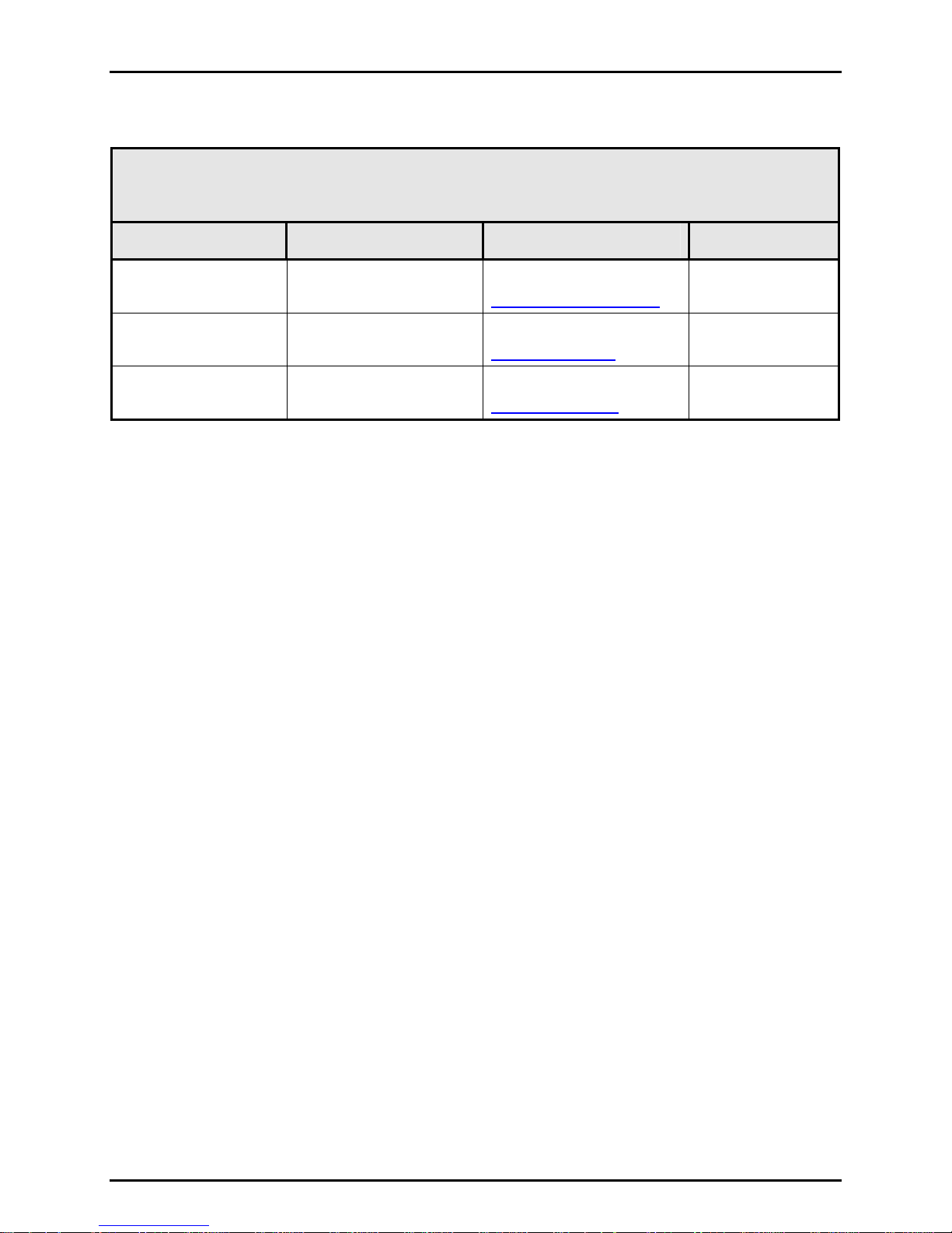
Table 2. DHI Authorized Service Providers
DH INSTRUMENTS, A FLUKE COMPANY
WWW.DHINSTRUMENTS.COM
AUTHORIZED SERVICE PROVIDERS
2006 MAY
COMPANY
DH Instruments, a Fluke
Company
Minerva Meettechniek B.V.
Nippon CalService, Inc.
4765 East Beautiful Lane
Phoenix AZ 85044-5318
USA
Chrysantstraat 1
3812 WX Amersfoort
the NETHERLANDS
2-9-1 Sengen, Tsukuba-Shi
Ibaraki Prefecture 305
JAPAN
ADDRESS
TELEPHONE,
FAX & EMAIL
Tel 602.431.9100
Fax 602.431.9559
cal.repair@dhinstruments.com
Tel (+31) 33.46.22.000
Fax (+31) 33.46.22.218
info@minervaipm.com
Tel 0298-55-8778
Fax 0298-55-8700
aohte@ohtegiken.co.jp
NORMAL SUPPORT
REGION
Worldwide
European Union
Japan/Asia
© 2008 DH Instruments, a Fluke Company Page 22
 Loading...