

Page 1

REPLACEMENT EPROM KIT FOR PG/FPG
TERMINALS, INCLUDES:
DESCRIPTION QTY PART NO.
REPLACEMENT EPROM KIT
For PG AND FPG TERMINALS
P/N 402372
Instruction Sheet
EPROM, PG/FPG Remote
(ver 1.01b)
1 402372
This is a replacement EPROM kit for PG or FPG
terminals.
REMOVAL OF PG/FPG VER 1.01a EPROM
n Disconnect power cord.
o Turn the PG/FPG Terminal on it’s back so all
four (4) rubber feet show: Remove the feet
using a small screwdriver to pop them out. This
will expose four cover screws (see Figure 1).
p Remove all four cover screws. Rotate PG or
FPG terminal so it is facing up.
q Remove enclosure cover from unit. Just lift off
the cover part way. The cover will not completely
remove due to cables.
r Disconnect cables prior to completely
removing cover. While holding the cover up,
unplug the ribbon cable to the display and the flex
cable for the membrane switch. The power supply
board will be exposed (see Figure 2).
Figure 1: PG/FPG Terminal bottom with feet removed.
s Detach three pin and six pin cables from power
supply board. The power supply is mounted in
four (4) places with a stainless steel screw, a lock
washer and a flat washer (see Figure 2).
t Remove the power supply board. Unscrew all four
of the stainless steel screws, lock washers, and flat
washers and retain them for use in remounting the
power supply.
The screws can be removed using a
2.5 mm Allen wrench. The power supply can now be
removed (see Figures 2 and 3).
Remove old EPROM Ver 1.01a. The old EPROM
is located at U5 on the PG/FPG Terminal main
board.
Figure 2: PG/FPG Terminal power supply board.
Figure 3: PG/FPG Terminal main board.
Power supply removed.
Page 2
REASSEMBLE THE PG/FPG TERMINAL
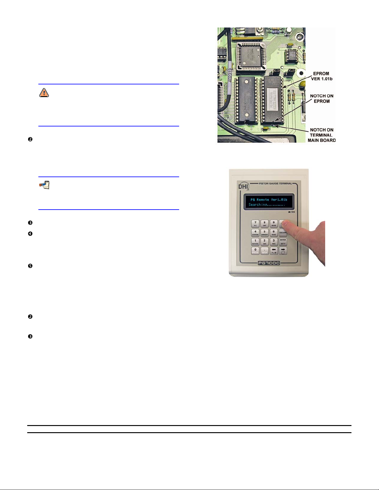
n Install new EPROM 402370 Ver 1.01b. The
EPROM is installed at U5 on the PG/FPG
Terminal main board lining up the notch on the
EPROM with notch silk screened on the terminal
main board (see Figure 4).
EPROM notch must line up with notch silk
screened on PG/FPG Terminal main board. If
installed incorrectly, the EPROM will be
destroyed on power up (see Figure 4).
Install the power supply board. Position the power
supply board in the correct mounting location with
the standoffs on the main board. Install all four of
the stainless steel screws, lock washers and flat
washers. Tighten using a 2.5 mm Allen wrench.
The flat washer should be positioned between
the surface of the power supply board and the
lock washer.
Figure 4: Orientation of EPROM on
PG/FPG Terminal main board.
Reattach 3 and 6 pin cables to power supply.
Assemble cover to base. First reconnect the
display ribbon cable and membrane switch flex
cable on the main board. Then close cover and
install cover screws.
Pop the four rubber feet back into position over
the four cover screws.
TESTING THE PG/FPG TERMINAL
n Plug in the PG/FPG terminal.
Turn power on whiling holding the ± key.
Display will show Ver 1.01b (see Figure 5).
Turn power off then on again (do not hold any
keys down). The initial display will show DH
Instruments, Inc.
Figure 5: Testing the PG/FPG Terminal
for correct version.
Document 560082 060328
DH Instruments, Inc.
4765 East Beautiful Lane
Phoenix AZ 85044-5318
USA
Tel 602.431.9100
Fax 602.431.9559
dhi@dhinstruments.com
www.dhinstruments.com
 Loading...