


LIGHTING LIMITED
Gecko Image Projector
Instruction & Maintenance
Manual

1 Connecting the Gecko 2
2 Gobos 4
3 Focusing the Gecko 6
4 Optional Gecko Accessories 8
5 Maintenance 12
6 Appendices 14
Contents

The Gecko is supplied with a 0.5m 3-core mains cable with no plug fitted.
The Gecko is available in a 230V European model and a 115V US model. It is
very important to check that you are using the correct model for your country to avoid the risk of damage to the unit. The unit must be connected to a
fused mains supply with a fuse rating no greater than 5A, and must be
earthed.
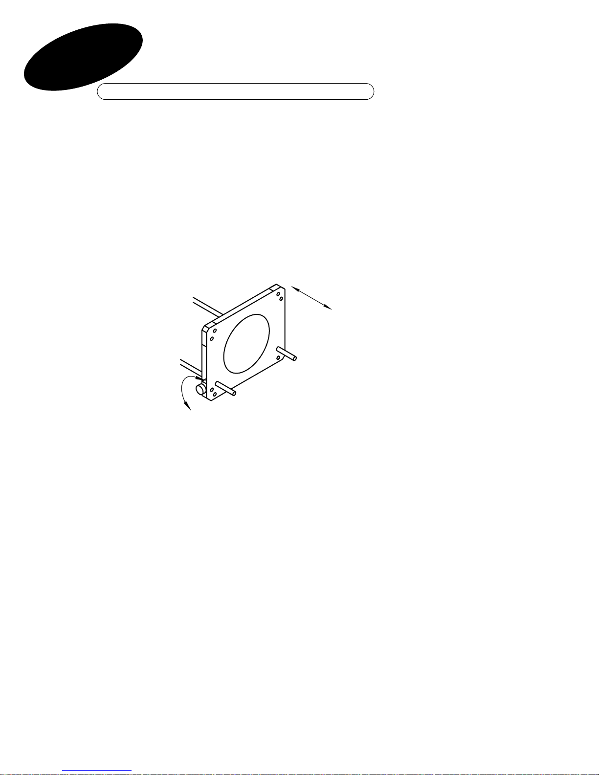
The Gecko is supplied with a universal mounting bracket as shown (Fig 1).
The bracket can be adjusted to allow for ceiling mounting, wall mounting or
floor / shelf mounting by loosening the "T" nut at the side of the unit and
rotating the arm around to the desired position as illustrated.
The hole in the bracket is a 12mm hole which allows for direct mounting
onto a large range of track adapters, ceiling mounts, wall brackets and
stands.
Please contact DHA for details about suitable mounting accessories.
Connecting The Gecko
2
1
Fig 1
Tighten
Loosen

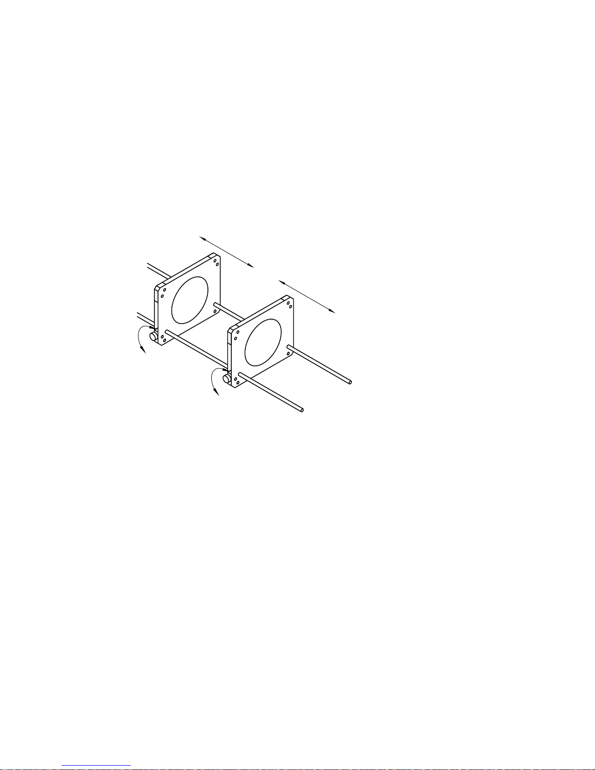
Additionally, the balance of the Gecko can be altered to compensate for any
accessories that may be used. To do this loosen the two nuts securing the
mounting bracket to the base of the unit and slide the bracket towards the
front or the rear of the unit and then re-tighten the nuts. Be careful not to
over-tighten the nuts on the base (Fig 2).
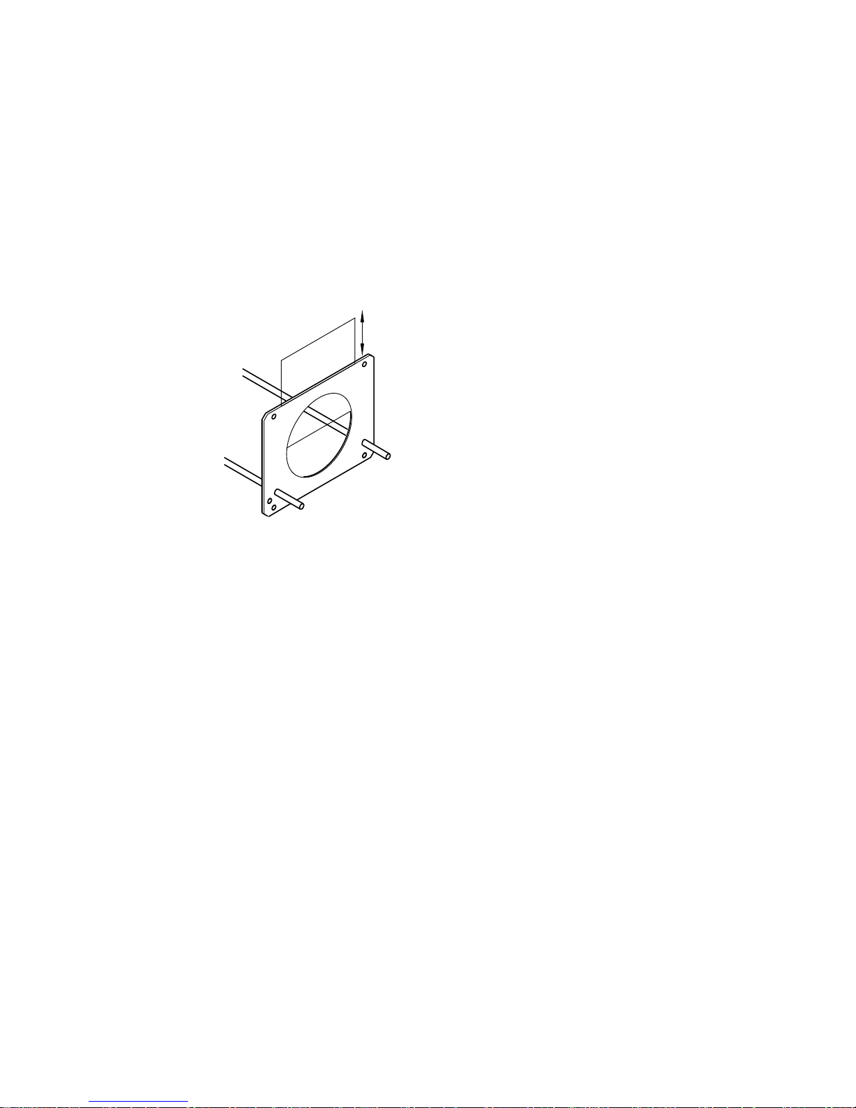
When choosing a mounting position for the Gecko, be sure that there is at
least 15cm clearance behind the unit so as not to obstruct the fan.
There should be at least 0.5m between the front of the Gecko and any
objects or walls. The mounting surface should be flat and free of moisture.
TThhee GGeecckkoo iiss ddeessiiggnneedd ffoorr iinnddoooorr uussee oonnllyy..
3
Tighten
Loosen
Fig 2

A gobo is an etched disc of metal or coated glass which allows an image to
be projected from the Gecko onto a wall or similar surface.
Gobos become very hot when they have been in a lantern for an extended
period of time, so it is important never to handle gobos until they have had
sufficient time to cool.
IInnsseerrttiinngg aa MMeettaall GGoobboo
The gobo holder on the Gecko is designed to take metal gobos on one side
and glass gobos on the other. Please refer to the drawings (Figs 3 + 4) to
see which side is used for inserting the metal and glass gobos taking special note of retaining tabs on each holder.
Take the gobo in one hand and rotate it so that when looking from the front
of the gecko, the gobo is upside down and back to front (Fig 3). This is
because the projector will invert the image when it is projected.
Lower the gobo into the holder so that it is held on 3 sides by the tabs bent
outwards from the holder (it may be necessary to bend these tabs slightly if
the gobo will not fit snugly).
To remove the gobo, gently slide the gobo upwards and away from
the holder.
Gobos
4
2
CCaauuttiioonn
Allow gobos to cool
before removing
Slide out gobo from
the retainer
Fig 3

IInnsseerrttiinngg aa GGllaassss GGoobboo
If you are using a glass gobo in the Gecko then you will need to make sure
that it is mounted in a glass gobo bezel (contact DHA for details).
The glass gobo should be inserted on the opposite side to the metal gobo,
please refer to the drawing (Fig 4) to see which side is used for inserting
the glass gobos.
Take the gobo in one hand by holding the bezel and ensuring that you do
not make contact with the surface of the glass itself. The bezel must be
positioned so that the flat rim is towards the gobo holder.
Gently ease forward the two tabs sufficiently to allow the bezel to slide
comfortably down into the holder, and then carefully release the tabs which
should now hold the bezel firmly in place.
To remove the gobo, gently ease the two tabs forward and slide the bezel
upwards and out of the holder.
NB: A 3mm space should be left between the glass gobo and the spill ring
to minimise heat build up of the unit.
5
Fig 4
CCaauuttiioonn
Allow gobos to cool
before removing
Slide bezel out of
the retainer
Ease tabs forward
to release bezel
Turn on the power and aim the unit towards the surface onto which the
image is to be projected.
FFooccuussiinngg aa SSttaannddaarrdd GGeecckkoo..
Once you have the unit positioned as required, loosen the thumbscrews on
either side of the gobo holder and move the gobo holder along the runners
until it is a few millimetres away from the front of the spill ring. Re–tighten
the thumbscrews to hold the gobo holder in place.
Next loosen the thumbscrews on each side of the lens and then slowly
move the lens forwards or backwards until the image becomes clear and
crisp, then re–tighten the two thumbscrews to hold the lens in place (Fig 5).
Focusing the Gecko
6
3
Fig 5
Tighten
Loosen
Focus
FFooccuussiinngg aa ZZoooomm GGeecckkoo
The process for focusing a zoom Gecko is very similar to the method
described opposite for the standard Gecko except that two lenses are
employed. The front lens is used to focus the image and the rear lens is
used to alter the size of the image. However, every time the size of the
image is altered, the image will go out of focus so the front lens will need
to be adjusted accordingly to restore the sharpness of the image.
Fig 6
Careful manipulation of the two lenses should provide you with a crisp,
clear image at the desired size (Fig 6).
7
Loosen
Tighten
Tighten
Loosen
Focus
Size
+
-

The following optional accessories are available for the Gecko. Please contact your retailer or DHA for details. Only use DHA approved accessories.
FFrraammiinngg SShhuutttteerrss
The framing shutters are usually used instead of a gobo where the Gecko is
being employed to highlight a particular object. Light can be contained to
frame an object without spilling onto the surrounding area (Fig 7). Shutters
can even be arranged to form a triangular aperture.
Fig 7
Accessories
8
4
CCaauuttiioonn
Framing shutters may
become hot if placed
close to the lamp
Rotate handles until
required framing angle
is obtained
CCoolloouurr HHoollddeerr
The colour holder allows the colour of the beam of light from the Gecko to
be changed to suit the surroundings by the use of a small piece of coloured
"gel" which is inserted into the holder (Fig 8).
9
Fig 8
Gel size
60mm x 65mm

AAnnttii FFllaarree AAppeerrttuurree
When the Gecko is used for projecting very intricate detail on an image, a
certain amount of "flare" will be seen which can make the image look
slightly soft, or fuzzy edged. This "flare" can be greatly reduced with the
use of the Anti Flare Aperture, which is mounted on the front of the Gecko
after all the other accessories are in place (Fig 9).
Fig 9
10
Tighten
Loosen
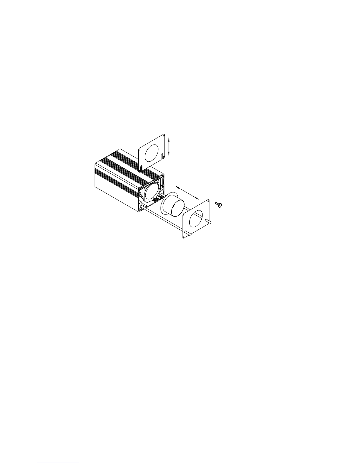
SSppiillll RRiinngg
The spill ring is a top-hat shaped ring that is mounted directly in front of
the lamp and stops any light from escaping from the side of the Gecko. This
is for use in areas where unwanted light spillage is not acceptable and is
supplied as a standard part of the Gecko.
11
Remove four screws
from front plate

Maintenance
5
Once installed correctly the Gecko should provide years of trouble free
operation. However as with all electrical appliances, regular maintenance
should be carried out to ensure that the quality of the light from the unit
remains constant.
1. Regularly clean the outside of the Gecko case with a dry, lint-free cloth
to remove any unwanted dust build up. Make sure that the fan guard at
the rear of the Gecko is not obscured or blocked in any way.
2. Regular cleaning of the lenses is essential as dust build–up on the sur–
face of the lens can reduce light output by up to 75%. Cleaning the lens
should be done by first wiping the surface of the lens with a dry, lint-free
cloth and then by cleaning the lens with methylated spirit.
NNBB:: TThhiiss mmuusstt oonnllyy bbee ddoonnee wwhheenn tthhee uunniitt iiss sswwiittcchheedd ooffff..
RReeppllaacciinngg tthhee LLaammpp
NNBB:: DDiissccoonnnneecctt tthhee GGeecckkoo ffrroomm tthhee mmaaiinnss ssuuppppllyy aanndd aallllooww ttoo ccooooll
1. Loosen the thumbscrews on the lenses, the gobo holder and any other
accessories that are fitted and slide them away from the lamp towards
the end of the runners.
2. Remove the four screws from the front plate of the Gecko. Remove the
front plate to allow access to the spill ring and lamp holder.
3. Slide out the lamp holder and lamp by gently easing them forwards out
of the Gecko.
4. Remove the lamp from its holder by sliding the lamp downward away
from the lamp holder plate.
5. Disconnect the lamp by pulling the lamp and the ceramic connector in
opposite directions as shown.
6. Taking a new lamp, push the ceramic connector onto the pins at
the back.
12

7. Place new lamp into holder by sliding towards the lamp holder plate.
Replace into Gecko making sure that the lamp holder plate is inserted
into the uppermost grooves in the body and is level (Fig 10).
8. Replace the front plate and tighten screws.
9. Return the accessories and lenses to their original positions and focus
the unit
13
Fig 10
Remove the four screws from
the front plate
Remove the spill ring
Slide out lamp holder & lamp
Remove lamp from holder
Separate lamp and
connector
Lamp holder PCB must slide
into the upper slots
CCaauuttiioonn
Allow the unit to cool before
replacing the lamp

Technical Specification 15
Clearance Requirements 16-19
Declaration of Conformity 20
Appendices
14
6

Technical Specification
Model: Dimmable Gecko Image Projector
Operating Voltage: 230V ac (115V ac)*
Power Consumption: 50-75W max or 100W
Lamp Type: MR16 100W (max)
Replacement lamp: 75EZZ (for 230V version)
Phillips Masterline 50W 24 degree
(for 110V version)*
Gobo Size: Size "E" 37.5mm diameter – metal
or glass
NB Glass gobos should be mounted
in a bezel
Weight: 0.7Kg
Dimensions: 450mm x 55mm x 65mm
* denotes the US model
15

16
Clearance required with luminaire suspended from brackets in rear position.
50°
90°
R 365 mm

17
Clearance required with luminaire suspended from brackets in forward position.
R 240 mm
45°
50°
R 160mm

18
Clearance required with luminaire supported by brackets in rear position.
90°
45°

19
Clearance required with luminaire supported by brackets in forward position.
45°
50°

Declaration of Conformity
20
DECLARATION OF CONFORMITY
ISO/IEC Guide 22 and EN 45014According to
Manufacturer's Name DHA Lighting Limited.
Manufacturer's Address
DHA Lighting Limited
284 - 302 Waterloo Road
London SEI 8RQ
England
declares, that the product(s):
GECKO Product Name:
75W / 100W – 230V
55W – 115V
115V or 230V 50/60Hz AC Product Options:
conform(s) to the following Product Specifications:
Safety:
EMC:
Supplementary Information:
Relevant clauses of
EN 60335–2–56: 1997
EN 61598–1 1997
EN 55015 1996
EN 61598 1995
Model Number(s):
The products herewith comply with the requirements of the Low
Voltage Directive 73/23/EEC and the EMC Directive 89/336/EEC. The
products were tested in a typical configuration.
Wyatt Enever
Director
Date
5/2/2000
European Contact:
DHA Lighting Limited
284 - 302 Waterloo Road London SEI 8RQ England
Tel +44 (020) 7771 2900 Fax +44 (020) 7771 2901

284 – 302 WATERLOO ROAD LONDON SE1 8RQ tel +44(0)20 7771 2900 fax +44 (0)20 7771 2901
e–mail sales@dhalighting.co.uk website www.dhalighting.co.uk isdn +44(0)20 7401 9202
 Loading...