

Page 1
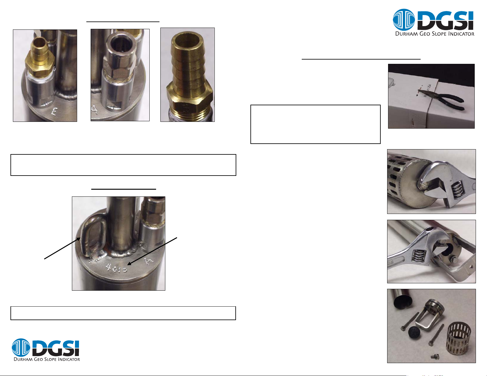
Hose Barb Sizes
Exhaust Hose Barb
3/8 in O.D. x 1/4 in I.D.
Nylon Tube.
Warning: All tubing or hoses attached to the pump must be secured with
an appropriately sized hose clamp.
Air Inlet
Push-To-Connect
¼ in O.D. Nylon Tubing
Fluid Discharge Hose Barb
1/2 in I.D. Buna-N Hose
Additional Info.
SRX-R PUMPS
Models TR-977
Quick Start Guide V1.2
Unpacking and Preparation
To remove the pump, separate the packing tape
and four staples from the sides of the box, then
pull apart the two box halves.
IMPORTANT! You will need to first remove
the internal packaging before the pump can
be used. A tag will be attached to the pump
alerting you of this.
To remove the internal packaging:
1. Remove the bottom bolt that secures the
screen with either a 5/16 in socket or an
adjustable wrench.
The loop is for
securing the pump
to the restraining
cable.
Additional drawings and parts lists can be found at www.DGSI.info
Durham Geo Slope Indicator
2175 West Park Court
Stone Mountain, GA 30087
When calling for parts
or service, please
include the serial
number of your pump.
+1.770.465.7557
Fax: 770.465.7447
e-mail: solutions@durhamgeo .com
www.DurhamGeo.com
2. Remove the two bolts from the bottom
valve seat using either a 5/16 in socket or
an adjustable wrench.
3. Remove the bottom valve seat and check-ball.
Pn # 603452
Page 2
Internal foam packaging
y
4. Now remove the pump body by simultaneously twisting the valve assembly
and pulling at the same time until the pump and the body easily separates.
5. Once separated, remove the upper-and-lower protective foam packaging.
Note: This packaging is provided to protect both the float and control rod from
damage during shipping. DGSI recommends that you save this packaging as
well as the box for any future shipping requirements.
To reassemble the pump, follow the above steps in reverse order. When
installing the bottom check-valve, it is recommended that you stand the pump
upside-down on the discharge hose-barb, then tighten the two bolts to pull the
O-ring seals into place.
Maintenance
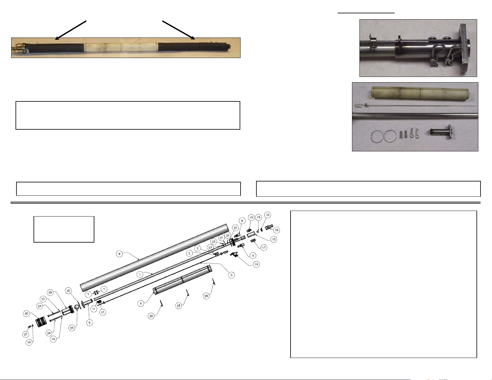
To clean the internal components
of the pump, remove the housing
as outlined in steps 1 – 4 in Packing
and Unpacking, then remove the
cotter and clevis pins from the
bottom assembly before sliding
the “T” assembly from the center
discharge tube.
The control rod and float can
now be removed for cleaning.
The float springs must first be
removed from the float (see
illustration below, #29).
Remove the barbed fittings to
clean the exhaust and air-inlet
valves from any debris.
To reassemble the pump, follow the above steps in reverse order.
Additional drawings and parts lists can be found at www.DGSI.info
Note: Some parts
listed are sold
as a kit.
onl
Warning: Any further disassembly should be carried out by DGSI.
2 2 603075 Cap Head Screw, 4-40 x 5/8”
3 1 603096 Air Valve Assembly
4 1 603092 Float Pump
5 1 603102 Control Rod Assembly
6 1 603069 Exhaust Valve Housing
7 2 603084 Clevis Pin 3/16”
8 1 603083 Pump Body
9 1 603081 Bottom “T” Weldment
10 3 603079 Seal Washer
11 2 603182 Hairpin Cotter Pin
12 1 603094 Check Valve Body
13 1 603268 Ball 3/8” Buna-N
14 1 603111 Air / Exhaust Valve Assembly
15 1 603266 Adaptor 1/8” MNPT x ¼” Hose.
16 1 603272 Adaptor ½” Barb x 3/8” MNPT
17 1 301240 ¼” Tube Adaptor x 1/8” MNPT
18 1 603270 Retaining Ring Check Valve
20 2 602450 O-Ring Pump
21 1 603071 Magnet Cover
22 1 603086 Magnet, 3/16” Dia.
23 2 603066 Cap Head Screw, 2 x 56
24 2 603289 Bolt 10-24 TPI x 2 ½”
25 1 915009 Buna-N Ball, 1”
27 1 603114 Bolt, 10-24 x ½”
28 1 603112 Bottom Intake Weldment
29 3 603282 Float Spring
30 1 603316 Screen Assembly, 2” SRX
No. Qty Part # Description
1 1 603095 Pump Head Weldment
 Loading...