


BARDY PANEL BED
ASSEMBLY INSTRUCTION
12850-Q

WARNING
Seller and Manufacturer disclaim all and any liability for
property damage, personal injury, or loss, direct, indirect, or
incidental, resulting from the incorrect assembly, inadequate
maintenance, improper use, or neglect of this product.
12850-Q
NOTICE
• Keep these assembly instructions for future reference.
• Do not use this product if there are missing parts,
damaged, or broken until repairs are made and/or factory
replacement parts are installed.
• Check all packing material carefully for small hardware
that may have become loose inside the carton
during shipment.
• Identify and count all hardware and parts to compare with
parts and hardware list.
• Follow assembly instructions closely. Improper assembly
can result in personal or property damage.
• Secure all bolts and screws before use.
• Every 90 days check all bolts and screws are secured.
• Some parts may have sharp corner or edges and may
be heavy.
• Do not use or store this product near open flames or
around flammable chemicals.
• When placing contents on non-carpeted flooring, it’s
recommended to use floor protection such as an area rug
or furniture pads. These are not included with the purchase.
REPLACEMENT PART OR HARDWARE REQUEST:
Request a replacement by logging into the marketplace
account in which the purchase was made and sending a
message to the seller. To assist in expediting the request
attach applicable images relevant to the request and/or
part number and quantity.
TOOLS REQUIRED:
ALLEN WRENCH
(PROVIDED)
PHILLIPS SCREWDRIVER
(NOT PROVIDED)

HARDWARE
KJ L M
M8 x 20
8 PCS
M6 x 30
20 PCS
N O
ALLEN KEY 100MM
1 PC
ALLEN KEY 70MM
R S
FLAT WASHER
12 PCS
SUPPORT LEG ADJUSTER
1 PC
4 PCS
M6 x 40
8 PCS
M6 x 50
P Q
SCREW
32MM
8 PCS
SPRING WASHER
8 PCS
10 PCS

BARDY PANEL BED PARTS
A
B
C1
C2
D1
HEADBOARD 1 PC
FOOTBOARD 1 PC
SIDE RAIL 4 PCS
F
G
H
SIDE RAIL
LEGS 2 PCS
SIDE RAIL SUPPORT
WOOD 4 PCS
SLAT 4 PCS
I
SUPPORT LEGS 4 PC
D2
E
T
HEADBOARD LEGS 2 PCS
SIDE WING
2 PCS
FOOTBOARD
SIDE LEG 2 PCS
ASSEMBLY INSTRUCTION
STEP 1
STEP 2
COMPONANTS AND HARDWARE TO BUILD THE BED IS LOCATED IN THE HEADBOARD.
UNZIP THE ZIPPER COMPARTMENT LOCATED AT THE BACK OF THE HEADBOARD TO
ACCESS THESE PARTS.
HEADBOARD BACK VIEW
ATTACH LEGS TO FOOTBOARD AND HEADBOARD AS SHOWN.
E
B
M
N
N
M
Q
R
R
D2
MATCH THE LABEL TO ENSURE THE HEADBOARD LEGS
ARE INSTALLED ONTO THE CORRECT SIDE OF THE HEADBOARD
A
D2
D1
HEADBOARD BACK VIEW
STEP 3
ATTACH PART J TO THE HEADBOARD AND FOOTBOARD BRACKETS AS SHOWN.
O
B
J
A
HEADBOARD FRONT VIEW

STEP 4
ATTACH THE SIDE WING (11) TO THE HEADBOARD (A).
MATCH THE LABEL
R
Q
L
N
A
T
TO INSTALL THE SIDE WINGS, UNZIP THE BLACK NON WOVEN
FABRIC AND REZIP ONCE THE SIDE WINGS ARE INSTALLED.
L
T
HEADBOARD BACK VIEW
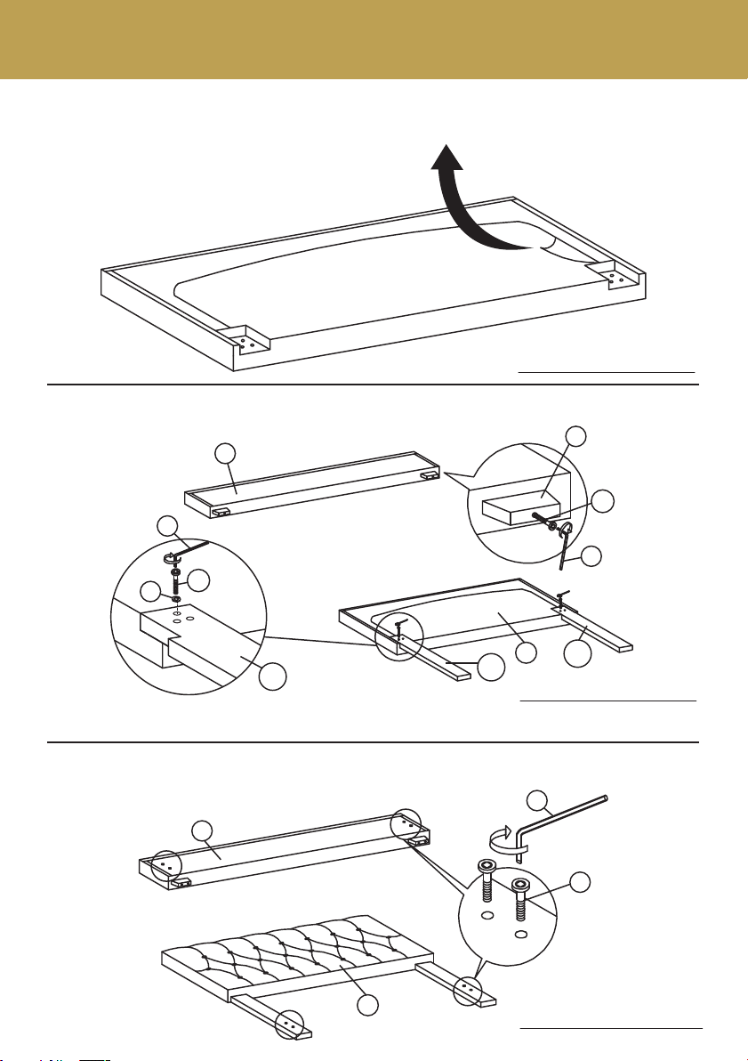
STEP 5
ATTACH THE SIDE RAIL SUPPORT WOOD (G) TO THE SIDE RAIL (C).
N
K
G
C2
C1

STEP 6
ATTACH THE SIDE RAIL LEG (F) TO THE SIDE RAIL (C).
N
K
R
F
C2
C1
STEP 7
ATTACH SIDE RAIL (C) TO HEADBOARD (A) AND FOOTBOARD (B)
BY PUSHING THE BRACKET DOWN TO FIT IT.
A
B
x4
C

STEP 8
ATTACH THE SUPPORT LEGS ( I) TO THE SLATS (H).
N
L
STEP 9
S
ROTATE PART S CLOCKWISE OR COUNTER CLOCKWISE
TO ADJUST SLAT HEIGHT FOR PROPER BOX SPRING SUPPORT
H
I
P
O
H
SCREW SLAT ONTO WOOD SLATE
SUPPORT ON THE SIDE RAIL.
DO NOT PLACE THE MATTRESS DIRECTLY ON TOP OF THE SLATS.
A BOX SPRING IS REQUIRED AND A LOW PROFILE BOX SPRING IS PREFERRED.
 Loading...