

Page 1
Specifications
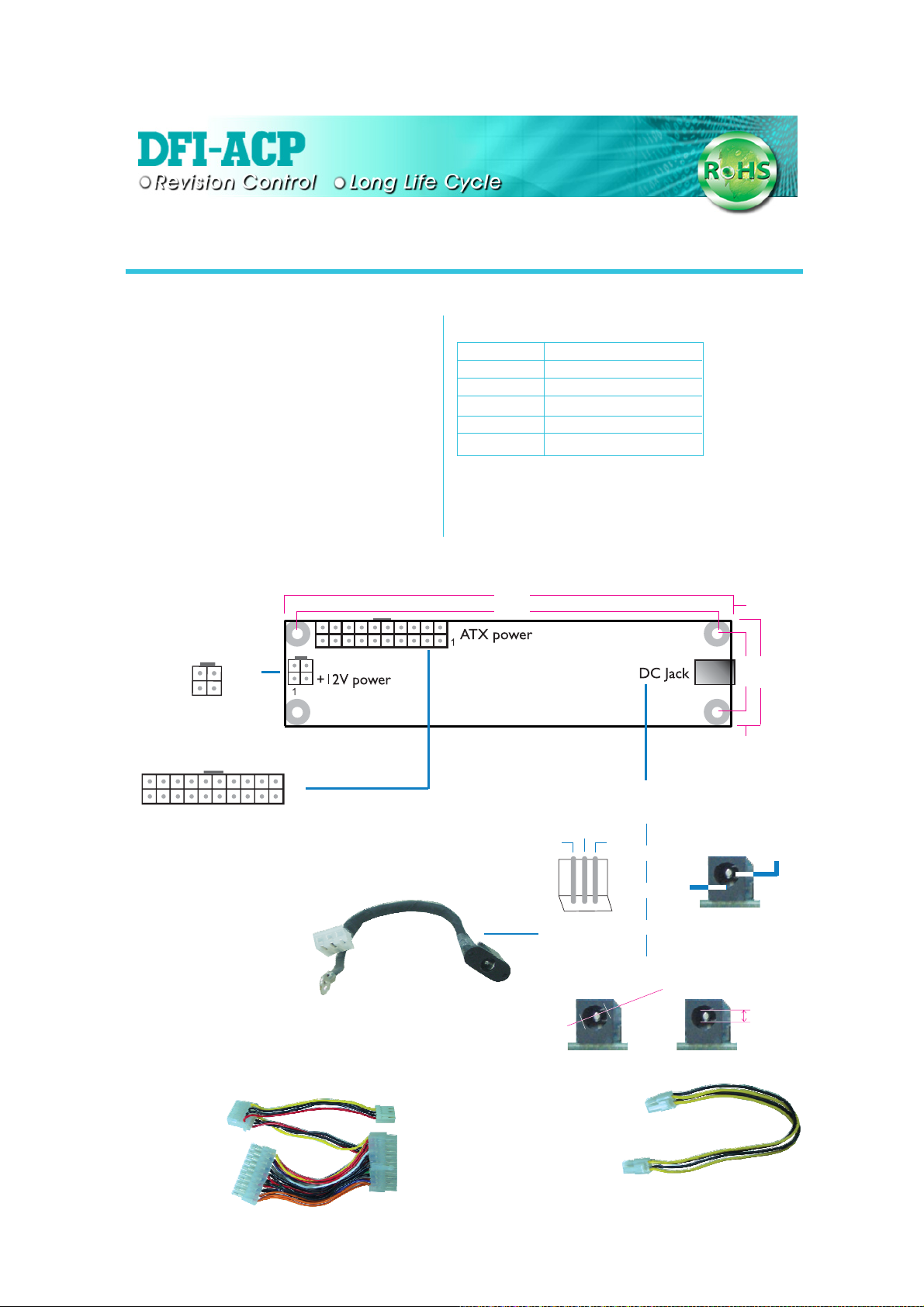
X100-DC20
DC to DC Module Board
Input Voltage: 16V - 22V
Maximum Output: 120W
Connectors
• One DC jack
• One 4-pin ATX 12V power
• One 20-pin ATX power
Environments
• Temperature: 0-60
o
C / 32-140oF
• Relative Humidity: 10%-90%
Board Layout and Pin Functions
+12V +12V
+5V
+5V
20
10
5VSB
+12V
12
N. C.
Ground
Ground
+5V
Ground
PW-OK
43
GroundGround
PS-ON
Ground
+5V
Ground
X
Ground
-12V
3.3V
Ground
3.3V
11
1
3.3V
X
Output Voltage: power for DC voltages
Output Voltage
+3.3V ±5%
+5V ±5%
5VSB ±5%
+12V ±5%
-12V ±10%
Output Current (maximum)
5.0A
5.0A
1.5A
6A
0.1A
DC Input: 0.25cm jack
PCB: 4 layers, 4 cm x 17 cm
height: 2.5 cm
17 cm
16 cm
X
The adapter card may come equipped with either
the 3-pin DC connector (left) or DC jack (right)
16V-22V
NC
GND
0.5 cm
3 cm
4 cm
0.5 cm
16V-22V
Cable
Connect to the ATX
power connector of
the motherboard
IDE power
Connect to the 3-pin
DC connector of
X100-DC20
FDD power
Connect to the ATX
power connector of
X100-DC20
Connect the AC
adapter directly to
this jack
Connect to the 4-pin
+12V power connector of
132
Use the cable on
the left to connect
the DC jack
0.63 cm
the motherboard
Connect to the 4-pin
+12V power connector
of X100-DC20
GND
Connect the AC
adapter directly to
this jack
0.25 cm
934-X100D1-200G
A89202715
 Loading...