

DFI WM342-KD Series, WM342-KD330, WM342-KD331 Installation Manual
1
WM342-KD Series Installation Guide
•
One WM342-KD330/WM342-KD331 system unit
•
1 SATA data cable
•
1 CPU cooler and 1 system fan
• HDD mounting screws
•
1 Quick Installation Guide
•
1 CD disk includes:
- Drivers / Manual
Package Contents
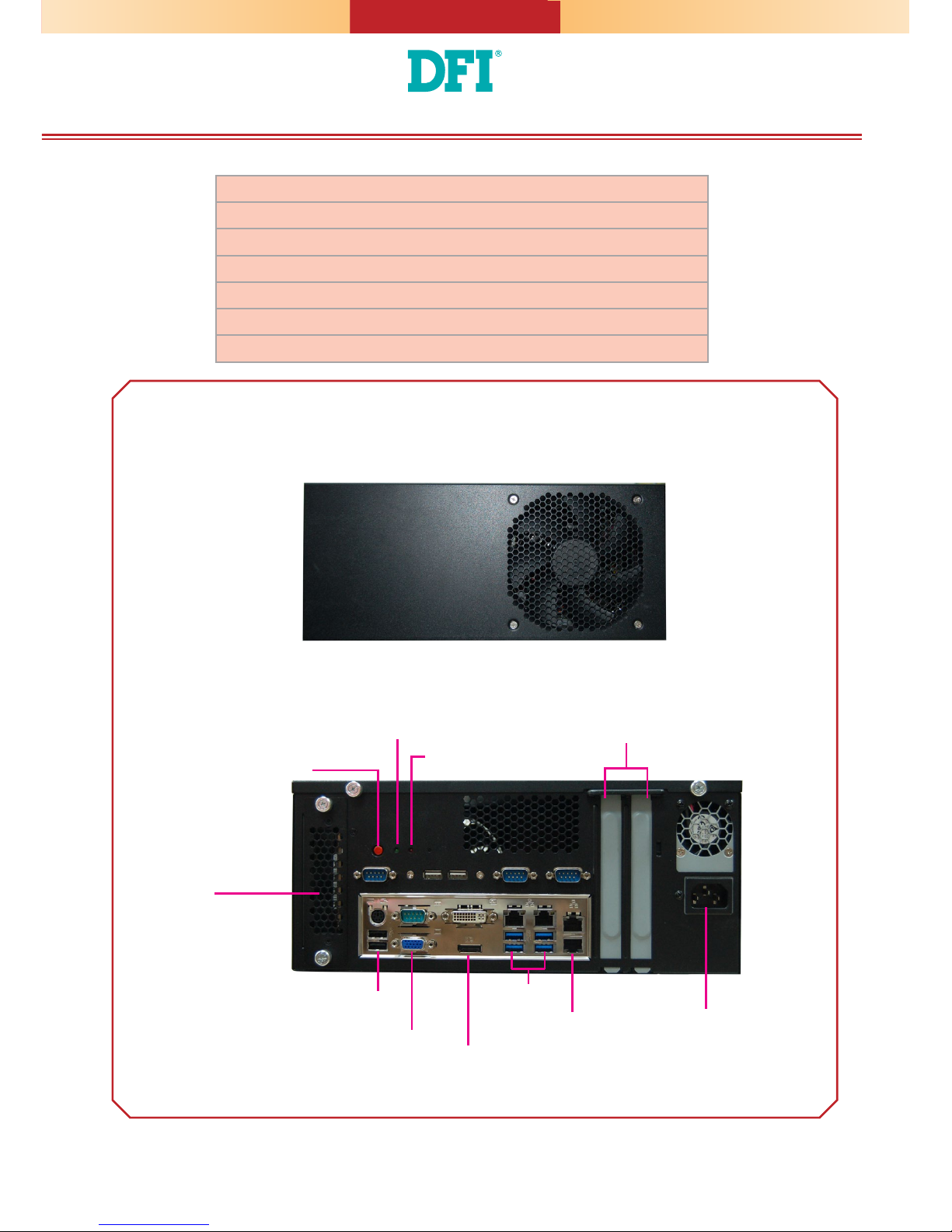
Panel
Front View
DFI reserves the right to change the specications at any time prior to the product's release. For the latest revision and for a more
details of the installation process, please refer to the user's manual on the website.
www.d.com
Rear View (WM342-KD330/WM342-KD331)
Expansion Slot
DVI-D
(DVI-I connector)
DP++
SATA
Drive Bay
for KD331:
LAN 3
LAN 4
or
for KD330:
Line-out
Mic-in
LAN 1 LAN 2
USB 3.0 1-4
PS/2 KB/MS
USB 2.0 1-2
COM1
VGA
Power LED (green)
HDD LED (red)
Power Button
AC Power
Socket
2
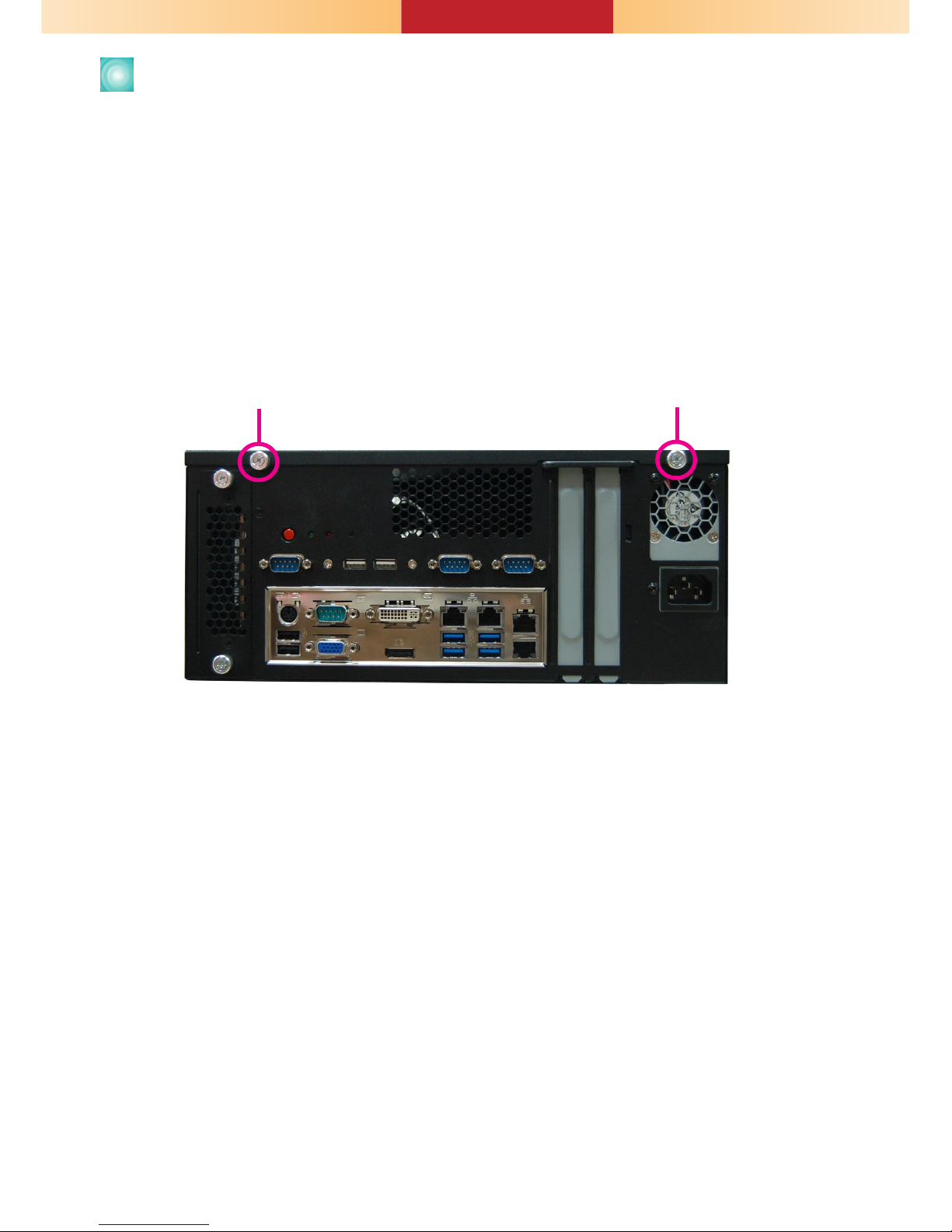
Opening the Chassis
Please observe the following guidelines and follow the procedure to open
the system.
1. Make sure the system and all other peripheral devices connected to it have
been powered off.
2. Disconnect all power cords and cables.
3. Remove the top cover by uninstalling the thumb screws.
Thumb screw
3
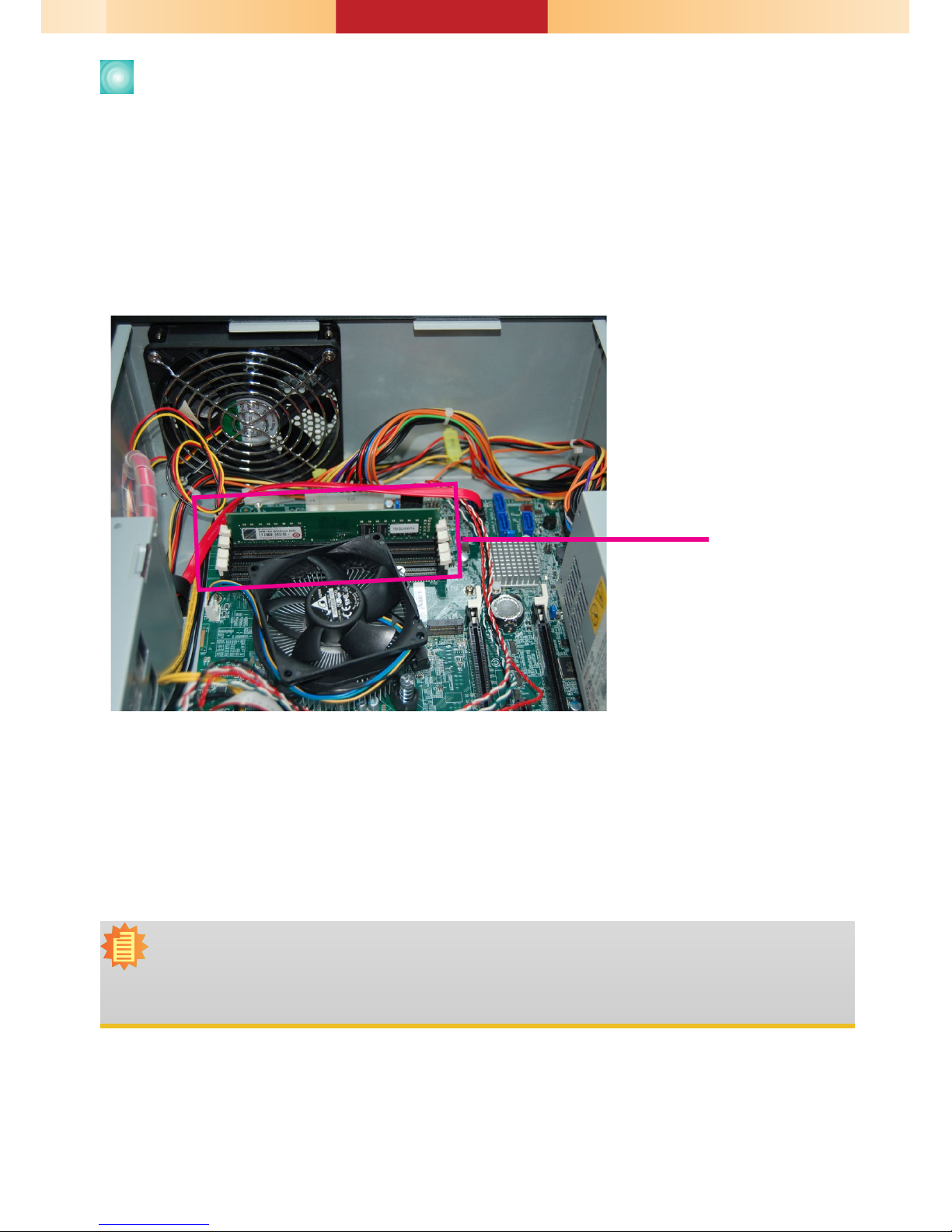
Installing a DIMM
1. Align the notch on the DIMM with the tab in the DIMM connector.
2. Press down on the DIMM until the release tabs spring back to secure the
DIMM in place.
Notes:
1. The WM342-KD330 is equipped with two or four DDR4 (dual channel) sockets depending
on the chipset.
2. The WM342-KD331 is equipped with four DDR4 (dual channel) sockets.
The installed DIMM
4
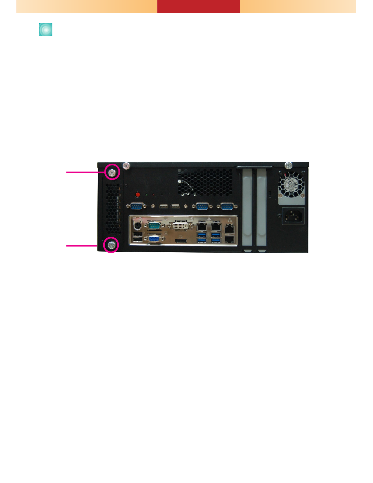
Installing 2.5" SATA Drive
1. Remove the thumb screws that secure the HDD drive bay to the chassis and
remove the drive bay.
Thumb screw
The system can accommodate two 2.5" SATA installation. Use the following proce-
dure to install a SATA drive onto the system.
 Loading...