

Page 1
www.dfi .com
1
Chapter 1 Introduction
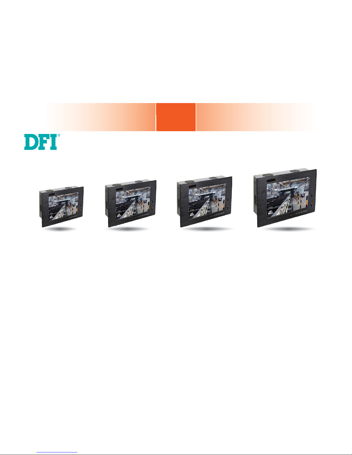
TPC121/150/170/190-SB
Touch Panel PC
User’s Manual
A24640503
Page 2

www.dfi .com
2
Chapter 1 Introduction
Copyright
This publication contains information that is protected by copyright. No part of it may be reproduced in any form or by any means or used to make any transformation/adaptation without
the prior written permission from the copyright holders.
This publication is provided for informational purposes only. The manufacturer makes no
representations or warranties with respect to the contents or use of this manual and specifically disclaims any express or implied warranties of merchantability or fitness for any particular
purpose. The user will assume the entire risk of the use or the results of the use of this document. Further, the manufacturer reserves the right to revise this publication and make changes
to its contents at any time, without obligation to notify any person or entity of such revisions
or changes.
Changes after the publication’s first release will be based on the product’s revision. The website
will always provide the most updated information.
© 2015. All Rights Reserved.
Trademarks
Product names or trademarks appearing in this manual are for identification purpose only and
are the properties of the respective owners.
FCC and DOC Statement on Class A
This equipment has been tested and found to comply with the limits for a Class A digital
device, pursuant to Part 15 of the FCC rules. These limits are designed to provide reasonable protection against harmful interference when the equipment is operated in a residential
installation. This equipment generates, uses and can radiate radio frequency energy and, if not
installed and used in accordance with the instruction manual, may cause harmful interference
to radio communications. However, there is no guarantee that interference will not occur in a
particular installation. If this equipment does cause harmful interference to radio or television
reception, which can be determined by turning the equipment off and on, the user is encouraged to try to correct the interference by one or more of the following measures:
• Reorient or relocate the receiving antenna.
• Increase the separation between the equipment and the receiver.
• Connect the equipment into an outlet on a circuit different from that to which the receiver
is connected.
• Consult the dealer or an experienced radio TV technician for help.
Notice:
1. The changes or modifications not expressly approved by the party responsible for compli-
ance could void the user’s authority to operate the equipment.
2. Shielded interface cables must be used in order to comply with the emission limits.
Page 3

www.dfi .com
3
Chapter 1 Introduction
Table of Contents
Copyright .............................................................................................................2
Trademarks ........................................................................................................2
FCC and DOC Statement on Class A ..................................................... 2
About this Manual ..........................................................................................4
Warranty ..............................................................................................................4
Static Electricity Precautions ......................................................................4
Safety Measures ..............................................................................................4
About the Package .........................................................................................5
Chapter 1 - Introduction .............................................................................6
Overview.........................................................................................................6
Key Features..................................................................................................7
Specifications ................................................................................................8
Getting to Know the TPC121/150/170/190-SB .................................12
Mechanical Dimensions ............................................................................14
Chapter 2 - Getting Started ..................................................................... 17
Preparing the System ...............................................................................17
Installing Devices .......................................................................................17
Configuring the BIOS ................................................................................ 17
Installing the Operating System ............................................................17
Installing the Drivers ................................................................................17
Chapter 3 - Installing Devices ................................................................18
Removing the Chassis Cover ..................................................................18
Installing an SODIMM ............................................................................... 19
Installing a SATA Drive ............................................................................. 20
Installing a Mini PCIe Card .....................................................................22
Latch .........................................................................................................22
Removing the Latch .................................................................................... 23
Installing the Mini PCIe Card ....................................................................... 24
Installing the PCI and PCIe x1 Expansion Cards .............................. 24
Connecting Cables to Terminal Blocks .................................................25
Chapter 4 - Jumper Settings ...................................................................26
Clear CMOS .................................................................................................. 26
PS/2 Power Select .....................................................................................26
USB Power Select ......................................................................................27
Power-on Select .........................................................................................27
COM 1 RS232/422/485 Select ................................................................ 28
COM 1 Signal Select .................................................................................28
Front Audio or Audio Amplifier Select..................................................29
Chapter 5 - Ports and Connectors ........................................................ 30
Front Panel I/O Port..................................................................................30
USB Ports ...................................................................................................30
Bottom Panel I/O Ports ............................................................................31
PS/2 Mouse and PS/2 Keyboard Ports .......................................................... 31
RJ45 LAN Ports ...........................................................................................32
USB Ports ...................................................................................................32
Graphics Interfaces ..................................................................................... 33
COM (Serial) Ports ...................................................................................... 34
Audio .........................................................................................................34
I/O Connectors ...........................................................................................35
SATA (Serial ATA) Connectors .....................................................................35
Digital I/O Connector and Digital I/O Power Connector................................. 36
Audio Amplifier Connector ........................................................................... 36
Chassis Intrusion Connector ........................................................................37
Cooling Fan Connectors...............................................................................37
Standby Power LED ....................................................................................38
Power Connectors ....................................................................................... 38
Expansion Slots .......................................................................................... 39
Front Panel Connector ................................................................................39
Battery ....................................................................................................... 40
SDVO Connector ......................................................................................... 40
SDVO-LVDS Daughterboard (optional) ..........................................................41
Installing the SDVO-LVDS Daughterboard onto the Motherboard (optional) ....43
Chapter 6 - Mounting Options ................................................................ 45
Wall Mount ................................................................................................... 45
Panel Mount ................................................................................................46
Chapter 7 - BIOS Setup ............................................................................48
Overview.......................................................................................................48
AMI BIOS Setup Utility .............................................................................49
Updating the BIOS ....................................................................................60
Notice: BIOS SPI ROM .............................................................................61
Chapter 8 - Supported Software ...........................................................62
Chapter 9 - Audio Configuration ...........................................................75
Appendix A - Smart Fan Setting Guide ..............................................77
Appendix B - Watchdog Sample Code ................................................79
Appendix C - System Error Message ................................................... 80
Appendix D - Troubleshooting Checklist ............................................81
Page 4

www.dfi .com
4
Chapter 1 Introduction
About this Manual
An electronic file of this manual is included in the CD. To view the user’s manual in the CD, insert the CD into a CD-ROM drive. The autorun screen (Main Board Utility CD) will appear. Click
“User’s Manual” on the main menu.
Warranty
1. Warranty does not cover damages or failures that arised from misuse of the product,
inability to use the product, unauthorized replacement or alteration of components and
product specifications.
2. The warranty is void if the product has been subjected to physical abuse, improper installation, modification, accidents or unauthorized repair of the product.
3. Unless otherwise instructed in this user’s manual, the user may not, under any circumstances, attempt to perform service, adjustments or repairs on the product, whether in or
out of warranty. It must be returned to the purchase point, factory or authorized service
agency for all such work.
4. We will not be liable for any indirect, special, incidental or consequencial damages to the
product that has been modified or altered.
Static Electricity Precautions
It is quite easy to inadvertently damage your PC, system board, components or devices even
before installing them in your system unit. Static electrical discharge can damage computer
components without causing any signs of physical damage. You must take extra care in handling them to ensure against electrostatic build-up.
1. To prevent electrostatic build-up, leave the system board in its anti-static bag until you are
ready to install it.
2. Wear an antistatic wrist strap.
3. Do all preparation work on a static-free surface.
4. Hold the device only by its edges. Be careful not to touch any of the components, contacts
or connections.
5. Avoid touching the pins or contacts on all modules and connectors. Hold modules or con
nectors by their ends.
Safety Measures
To avoid damage to the system:
• Use the correct AC input voltage range.
To reduce the risk of electric shock:
• Unplug the power cord before removing the system chassis cover for installation or servic-
ing. After installation or servicing, cover the system chassis before plugging the power cord.
Battery:
• Danger of explosion if battery incorrectly replaced.
• Replace only with the same or equivalent type recommend by the manufacturer.
• Dispose of used batteries according to local ordinance.
Important:
Electrostatic discharge (ESD) can damage your processor, disk drive and other components. Perform the upgrade instruction procedures described at an ESD workstation only. If such a station is not available, you can provide some ESD protection by
wearing an antistatic wrist strap and attaching it to a metal part of the system chassis. If a wrist strap is unavailable, establish and maintain contact with the system
chassis throughout any procedures requiring ESD protection.
Page 5

www.dfi .com
5
Chapter 1 Introduction
About the Package
The package contains the following items. If any of these items are missing or damaged,
please contact your dealer or sales representative for assistance.
• 1 12”/15”/17”/19” Touch Panel PC
• 1 120W Power adapter
• 1 CD disk includes
- Manual
- Drivers
• 1 Quick Installation Guide
Optional Items
• Wall Mount kit
• Panel Mount kit
• Power Cord
The board and accessories in the package may not come similar to the information listed
above. This may differ in accordance to the sales region or models in which it was sold. For
more information about the standard package in your region, please contact your dealer or
sales representative.
Before Using the System
Before powering-on the system, prepare the basic system components.
If you are installing the system board in a new system, you will need at least the following
internal components.
• Memory module
• Storage devices such as hard disk drive, CD-ROM, etc.
You will also need external system peripherals you intend to use which will normally include at
least a keyboard, a mouse and a video display monitor.
Safety Precautions
• Use the correct DC input voltage range.
• Unplug the power cord before removing the system chassis cover for installation or servicing. After installation or servicing, cover the system chassis before plugging the power cord.
• Danger of explosion if battery incorrectly replaced.
• Replace only with the same or equivalent type recommend by the manufacturer.
• Dispose of used batteries according to local ordinance.
• Keep this system away from humidity.
• Place the system on a stable surface. Dropping it or letting it fall may cause damage.
• The openings on the system are for air ventilation to protect the system from overheating.
DO NOT COVER THE OPENINGS.
• Place the power cord in such a way that it will not be stepped on. Do not place anything on
top of the power cord. Use a power cord that has been approved for use with the system
and that it matches the voltage and current marked on the system’s electrical range label.
• If the system will not be used for a long time, disconnect it from the power source to avoid
damage by transient overvoltage.
• If one of the following occurs, consult a service personnel:
- The power cord or plug is damaged.
- Liquid has penetrated the system.
- The system has been exposed to moisture.
- The system is not working properly.
- The system dropped or is damaged.
- The system has obvious signs of breakage.
• The unit uses a three-wire ground cable which is equipped with a third pin to ground the
unit and prevent electric shock. Do not defeat the purpose of this pin. If your outlet does
not support this kind of plug, contact your electrician to replace the outlet.
• Disconnect the system from the DC outlet before cleaning. Use a damp cloth. Do not use
liquid or spray detergents for cleaning.
Page 6
www.dfi .com
6
Chapter 1 Introduction
Chapter 1 - Introduction
Chapter 1
Overview
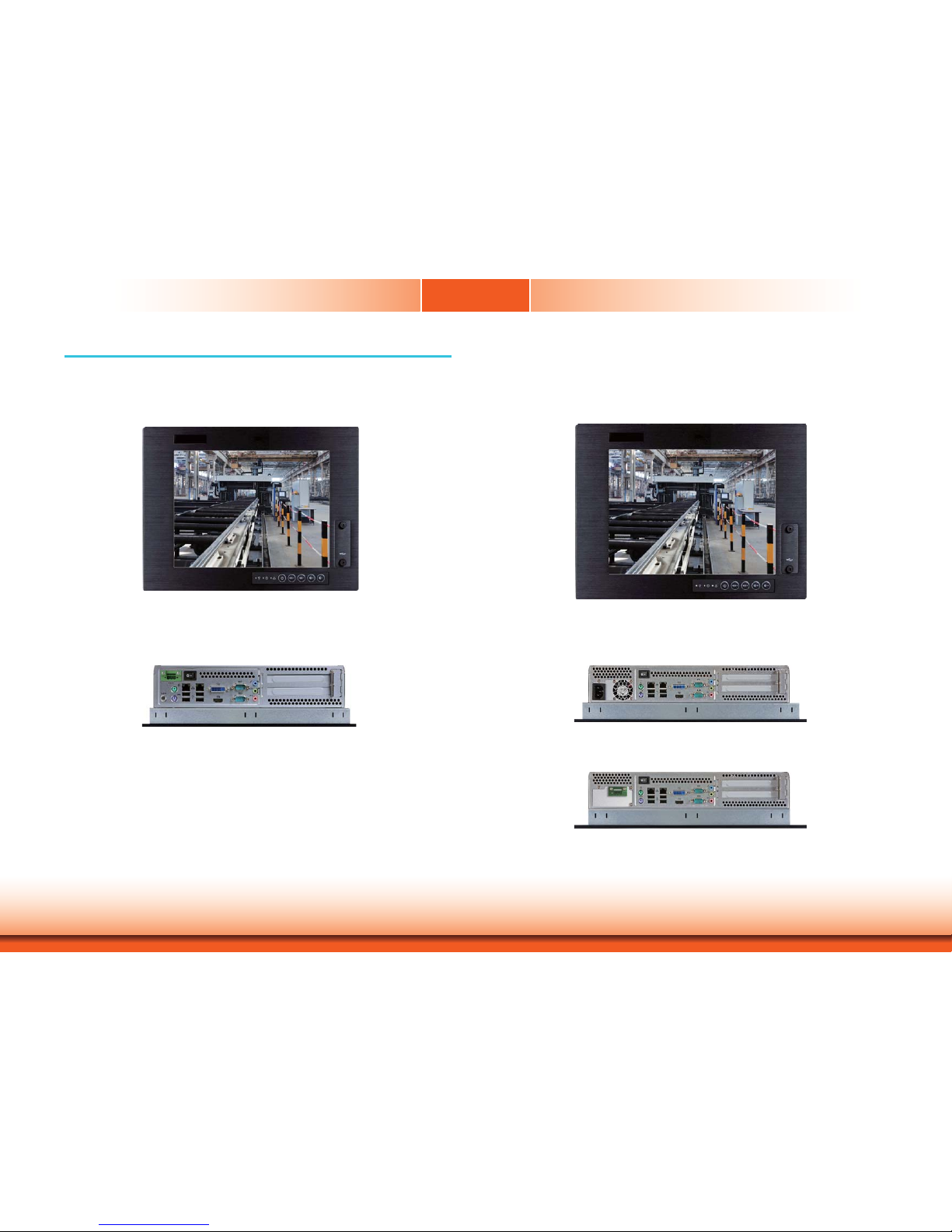
TPC121
TPC150/TPC170/TPC190-SB
Page 7

www.dfi .com
7
Chapter 1 Introduction
Key Features
TPC121/150/170/190-SB
Processor
3rd/2nd Generation Intel® CoreTM processors
Chipset
Intel® H61 Express Chipset
LAN
2 LAN ports
COM
2 COM ports
Dual Displays
HDMI and DVI-I
USB
2 Type A USB 2.0/1.1 ports at the front panel
4 Type A USB 2.0/1.1 ports at the bottom
Audio
Mic-in, Line-in, Line-out
2 3W speakers (left and right sides)
Chapter 1
Page 8

www.dfi .com
8
Chapter 1 Introduction
I/O Ports
• Front
-
2 Type A USB 2.0/1.1 ports
-
5 function keys: power, volume, and brightness
-
3 LED indicators: Power, HDD, Alarm
- 1
built-in antenna
• Bottom
- 1 DB-9 RS232/422/485 COM
- 1 DB-9 RS232 COM
- 1 PS/2 keyboard
- 1 PS/2 mouse
-
4 Type A USB 2.0/1.1
-
3 audio jacks: Mic-in, Line-in, Line-out
- 2 RJ45 LAN with LEDs
- 1 DVI-I
- 1 HDMI
- 1 power switch
- 1 +19V DC-in jack or 16-30V 3-pole terminal block
Expansion
• 1 PCIe x1 and 1 PCI (X100-3PE2)
• 2 PCI (X100-2P1M)
• 2 Mini PCIe
- Supports PCIe and USB signals for Wi-Fi module
- Supports half/full size Mini PCIe card
Front Panel
Protection
•
IP65 (Dust Tight; Water Proof protection)
Construction
• Aluminum front bezel
• Rear panel: sheet metal
Mounting
• VESA mount: 75x75 and 100x100
• Wall mount bracket* (optional)
• Panel mount: mounting clamp* (optional)
Dimensions
• 345mm x 265mm x 103mm (W x H x D)
Weight
•
6.5 kg
OS Support
• Windows XP, WES 2009, POSReady 2009, Windows 7, WES 7
• Linux (Distribution available upon request)
Certifi cation
• CE
• FCC Class A
• RoHS
Specifi cations
TPC121
Processor System
• Processors:
- 3rd generation Intel
®
CoreTM processors
- 2nd generation Intel
®
CoreTM processors
- Supports up to 65W TDP
• Intel
®
H61 Express chipset
Memory
• Two DDR3 1333/1600MHz SODIMM sockets (3rd generation processors)
Two DDR3 1066/1333MHz SODIMM sockets (2nd generation processors)
• Supports up to 16GB system memory
LCD and
Touch Screen
• 12.1” 1024x768 TFT LCD panel with touch screen
• Supports 5-wire Resistive Touch
• 30,000 MTBF LED backlight
• Brightness (cd/m²): 500
Graphics
• Intel® HD Graphics
• Display ports: HDMI and DVI-I
• HDMI and DVI-I display resolution up to 1920x1200
Storage
• 1 2.5" SATA drive bay
- SATA 2.0 port with data transfer rate up to 3Gb/s
• 1 optical drive bay* (optional)
Ethernet
• 1 Intel® W82579LM Gigabit Ethernet Controller
• 1 Intel
®
W82574L Gigabit Ethernet Controller
Audio
• Realtek ALC886 5.1-channel High Defi nition Audio
• Two 3W speakers (left and right sides)
COM
• 1 RS232/422/485 COM port
• 1 RS232 COM port
USB
• 2 Type A USB 2.0/1.1 ports at the front panel
• 4 Type A USB 2.0/1.1 ports at the bottom
Power
• Power input voltage
- Standard: 19~24V DC-in jack
- Option: 24V DC-in 3-pole terminal block
Cooling System
• Smart fan system control suitable for quiet environments
Environment
• Temperature
- Operating: -10
o
C ~ 50oC
- Storage: -20
o
C ~ 60oC
• Relative Humidity
- 90% RH at 50
o
C, 1 week
• Corrosion
- 4 periods of 7 days at 50
o
C with 90-95% relative humidity after 2 hours salt
spray or waiver
Vibration
• Operating: 1G, 5~500Hz
• Non-operating: 1.5G, 5~25Hz
• IEC 68-2-64 compliant
Shock
• Operating: 3G peak acceleration (11 msec. duration)
• Non-operating: 10G peak acceleration (11 msec. duration)
• IEC 68-2-27 compliant
Chapter 1
Note:
*Optional and is not supported in standard model. Please contact your sales representative for more information.
Page 9

www.dfi .com
9
Chapter 1 Introduction
Chapter 1
Specifi cations
TPC150
I/O Ports
• Front
-
2 Type A USB 2.0/1.1 ports
-
5 function keys: power, volume, and brightness
-
3 LED indicators: Power, HDD, Alarm
- 1
built-in antenna
• Bottom
- 1 DB-9 RS232/422/485 COM
- 1 DB-9 RS232 COM
- 1 PS/2 keyboard
- 1 PS/2 mouse
-
4 Type A USB 2.0/1.1
-
3 audio jacks: Mic-in, Line-in, Line-out
- 2 RJ45 LAN with LEDs
- 1 DVI-I
- 1 HDMI
- 1 power switch
Expansion
• 1 PCIe x1 and 1 PCI (X100-3PE2)
• 2 PCI (X100-2P1M)
• 2 Mini PCIe
- Supports PCIe and USB signals for Wi-Fi module
- Supports half/full size Mini PCIe card
Front Panel
Protection
•
IP65 (Dust Tight; Water Proof protection)
Construction
• Aluminum front bezel
• Rear panel: sheet metal
Mounting
• VESA mount: 75x75 and 100x100
• Wall mount bracket* (optional)
• Panel mount: mounting clamp* (optional)
Dimensions
• 410mm x 320mm x 106mm (W x H x D)
Weight
•
7.8 k g
OS Support
• Windows XP, WES 2009, POSReady 2009, Windows 7, WES 7
• Linux (Distribution available upon request)
Certifi cation
• CE
• FCC Class A
• RoHS
• UL
Processor System
• Processors:
- 3rd generation Intel
®
CoreTM processors
- 2nd generation Intel
®
CoreTM processors
- Supports up to 65W TDP
• Intel
®
H61 Express chipset
Memory
• Two DDR3 1333/1600MHz SODIMM sockets (3rd generation processors)
Two DDR3 1066/1333MHz SODIMM sockets (2nd generation processors)
• Supports up to 16GB system memory
LCD and
Touch Screen
• 15” 1024x768 TFT LCD panel with touch screen
• Supports 5-wire Resistive Touch
• 50,000 MTBF LED backlight
• Brightness (cd/m²): 250
Graphics
• Intel® HD Graphics
• Display ports: HDMI and DVI-I
• HDMI and DVI-I display resolution up to 1920x1200
Storage
• 2 2.5" SATA drive bays
- SATA 2.0 port with data transfer rate up to 3Gb/s
• 1 optical drive bay* (optional)
Ethernet
• 1 Intel W82579LM Gigabit Ethernet Controller
• 1 Intel W82574L Gigabit Ethernet Controller
Audio
• Realtek ALC886 5.1-channel High Defi nition Audio
• Two 3W speakers (left and right sides)
COM
• 1 RS232/422/485 COM port
• 1 RS232 COM port
USB
• 2 Type A USB 2.0/1.1 ports at the front panel
• 4 Type A USB 2.0/1.1 ports at the bottom
Power
• Power input voltage
- Standard: ATX power type, AC 100-240V, 3.5A, 250W
- Option: 24V DC-in 3-pole terminal block
- Available upon request: 12V and 30V DC-in 3-pole terminal block
Cooling System
• Smart fan system control suitable for quiet environments
Environment
• Temperature
- Operating: -10oC ~ 50oC
- Storage: -20oC ~ 60oC
• Relative Humidity
- 90% RH at 50oC, 1 week
• Corrosion
- 4 periods of 7 days at 50oC with 90-95% relative humidity after 2 hours salt
spray or waiver
Vibration
• Operating: 1G, 5~500Hz
• Non-operating: 1.5G, 5~25Hz
• IEC 68-2-64 compliant
Shock
• Operating: 3G peak acceleration (11 msec. duration)
• Non-operating: 10G peak acceleration (11 msec. duration)
• IEC 68-2-27 compliant
Note:
*Optional and is not supported in standard model. Please contact your sales representative for more information.
Page 10

www.dfi .com
10
Chapter 1 Introduction
Chapter 1
Specifi cations
TPC170
I/O Ports
• Front
-
2 Type A USB 2.0/1.1 ports
-
5 function keys: power, volume, and brightness
-
3 LED indicators: Power, HDD, Alarm
- 1
built-in antenna
• Bottom
- 1 DB-9 RS232/422/485 COM
- 1 DB-9 RS232 COM
- 1 PS/2 keyboard
- 1 PS/2 mouse
-
4 Type A USB 2.0/1.1
-
3 audio jacks: Mic-in, Line-in, Line-out
- 2 RJ45 LAN with LEDs
- 1 DVI-I
- 1 HDMI
- 1 power switch
Expansion
• 1 PCIe x1 and 1 PCI (X100-3PE2)
• 2 PCI (X100-2P1M)
• 2 Mini PCIe
- Supports PCIe and USB signals for Wi-Fi module
- Supports half/full size Mini PCIe card
Front Panel
Protection
•
IP65 (Dust Tight; Water Proof protection)
Construction
• Aluminum front bezel
• Rear panel: sheet metal
Mounting
• VESA mount: 75x75 and 100x100
• Wall mount bracket* (optional)
• Panel mount: mounting clamp* (optional)
Dimensions
• 443mm x 363mm x 106mm (W x H x D)
Weight
•
9.6 kg
OS Support
• Windows XP, WES 2009, POSReady 2009, Windows 7, WES 7
• Linux (Distribution available upon request)
Certifi cation
• CE
• FCC Class A
• RoHS
Processor System
• Processors:
- 3rd generation Intel
®
CoreTM processors
- 2nd generation Intel
®
CoreTM processors
- Supports up to 65W TDP
• Intel
®
H61 Express chipset
Memory
• Two DDR3 1333/1600MHz SODIMM sockets (3rd generation processors)
Two DDR3 1066/1333MHz SODIMM sockets (2nd generation processors)
• Supports up to 16GB system memory
LCD and
Touch Screen
• 17” 1280x1024 TFT LCD panel with touch screen
• Supports 5-wire Resistive Touch
• 50,000 MTBF LED backlight
• Brightness (cd/m²): 380
Graphics
• Intel® HD Graphics
• Display ports: HDMI and DVI-I
• HDMI and DVI-I display resolution up to 1920x1200
Storage
• 2 2.5" SATA drive bays
- SATA 2.0 port with data transfer rate up to 3Gb/s
• 1 optical drive bay* (optional)
Ethernet
• 1 Intel W82579LM Gigabit Ethernet Controller
• 1 Intel W82574L Gigabit Ethernet Controller
Audio
• Realtek ALC886 5.1-channel High Defi nition Audio
• Two 3W speakers (left and right sides)
COM
• 1 RS232/422/485 COM port
• 1 RS232 COM port
USB
• 2 Type A USB 2.0/1.1 ports at the front panel
• 4 Type A USB 2.0/1.1 ports at the bottom
Power
• Power input voltage
- Standard: ATX power type, AC 100-240V, 3.5A, 250W
- Option: 24V DC-in 3-pole terminal block
- Available upon request: 12V and 30V DC-in 3-pole terminal block
Cooling System
• Smart fan system control suitable for quiet environments
Environment
• Temperature
- Operating: -10oC ~ 50oC
- Storage: -20oC ~ 60oC
• Relative Humidity
- 90% RH at 50oC, 1 week
• Corrosion
- 4 periods of 7 days at 50oC with 90-95% relative humidity after 2 hours salt
spray or waiver
Vibration
• Operating: 1G, 5~500Hz
• Non-operating: 1.5G, 5~25Hz
• IEC 68-2-64 compliant
Shock
• Operating: 3G peak acceleration (11 msec. duration)
• Non-operating: 10G peak acceleration (11 msec. duration)
• IEC 68-2-27 compliant
Note:
*Optional and is not supported in standard model. Please contact your sales representative for more information.
Page 11

www.dfi .com
11
Chapter 1 Introduction
Chapter 1
I/O Ports
• Front
-
2 Type A USB 2.0/1.1 ports
-
5 function keys: power, volume, and brightness
-
3 LED indicators: Power, HDD, Alarm
- 1
built-in antenna
• Bottom
- 1 DB-9 RS232/422/485 COM
- 1 DB-9 RS232 COM
- 1 PS/2 keyboard
- 1 PS/2 mouse
-
4 Type A USB 2.0/1.1
-
3 audio jacks: Mic-in, Line-in, Line-out
- 2 RJ45 LAN with LEDs
- 1 DVI-I
- 1 HDMI
- 1 power switch
Expansion
• 1 PCIe x1 and 1 PCI (X100-3PE2)
• 2 PCI (X100-2P1M)
• 2 Mini PCIe
- Supports PCIe and USB signals for Wi-Fi module
- Supports half/full size Mini PCIe card
Front Panel
Protection
•
IP65 (Dust Tight; Water Proof protection)
Construction
• Aluminum front bezel
• Rear panel: sheet metal
Mounting
• VESA mount: 75x75 and 100x100
• Wall mount bracket* (optional)
• Panel mount: mounting clamp* (optional)
Dimensions
• 472mm x 391mm x 116mm (W x H x D)
Weight
•
10.2 kg
OS Support
• Windows XP, WES 2009, POSReady 2009, Windows 7, WES 7
• Linux (Distribution available upon request)
Certifi cation
• CE
• FCC Class A
• RoHS
Specifi cations
TPC190-SB
Processor System
• Processors:
- 3rd generation Intel
®
CoreTM processors
- 2nd generation Intel
®
CoreTM processors
- Supports up to 65W TDP
• Intel
®
H61 Express chipset
Memory
• Two DDR3 1333/1600MHz SODIMM sockets (3rd generation processors)
Two DDR3 1066/1333MHz SODIMM sockets (2nd generation processors)
• Supports up to 16GB system memory
LCD and
Touch Screen
• 19” 1280x1024 TFT LCD panel with touch screen
• Supports 5-wire Resistive Touch
• 50,000 MTBF LED backlight
• Brightness (cd/m²): 350
Graphics
• Intel® HD Graphics
• Display ports: HDMI and DVI-I
• HDMI and DVI-I display resolution up to 1920x1200
Storage
• 2 2.5" SATA drive bays
- SATA 2.0 port with data transfer rate up to 3Gb/s
• 1 optical drive bay* (optional)
Ethernet
• 1 Intel W82579LM Gigabit Ethernet Controller
• 1 Intel W82574L Gigabit Ethernet Controller
Audio
• Realtek ALC886 5.1-channel High Defi nition Audio
• Two 3W speakers (left and right sides)
COM
• 1 RS232/422/485 COM port
• 1 RS232 COM port
USB
• 2 Type A USB 2.0/1.1 ports at the front panel
• 4 Type A USB 2.0/1.1 ports at the bottom
Power
• Power input voltage
- Standard: ATX power type, AC 100-240V, 3.5A, 250W
- Option: 24V DC-in 3-pole terminal block
- Available upon request: 12V and 30V DC-in 3-pole terminal block
Cooling System
• Smart fan system control suitable for quiet environments
Environment
• Temperature
- Operating: -10oC ~ 50oC
- Storage: -20oC ~ 60oC
• Relative Humidity
- 90% RH at 50oC, 1 week
• Corrosion
- 4 periods of 7 days at 50oC with 90-95% relative humidity after 2 hours salt
spray or waiver
Vibration
• Operating: 1G, 5~500Hz
• Non-operating: 1.5G, 5~25Hz
• IEC 68-2-64 compliant
Shock
• Operating: 3G peak acceleration (11 msec. duration)
• Non-operating: 10G peak acceleration (11 msec. duration)
• IEC 68-2-27 compliant
Note:
*Optional and is not supported in standard model. Please contact your sales representative for more information.
Page 12
www.dfi .com
12
Chapter 1 Introduction
Getting to Know the TPC121/150/170/190-SB
Chapter 1
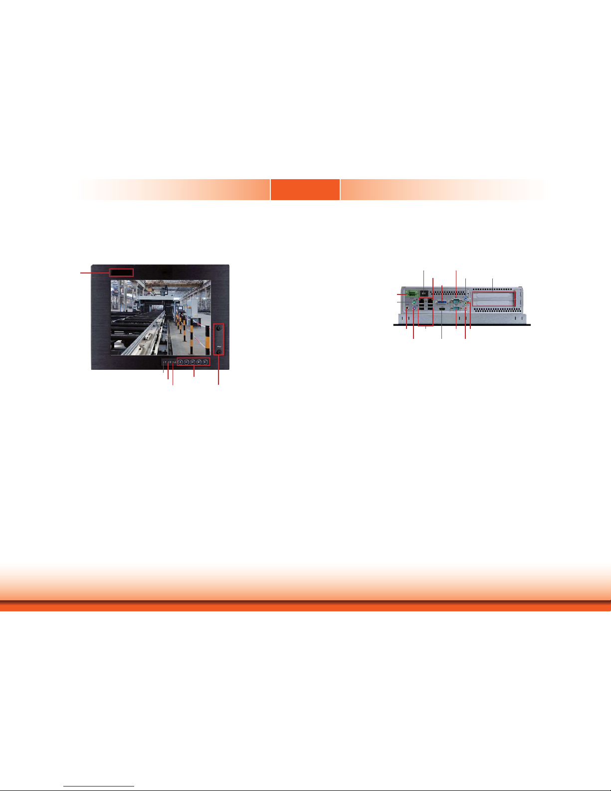
Front View
USB Ports
Used to connect USB 2.0/1.1 devices.
Function Keys
Used to navigate.
Alarm LED
Indicates the status when the CPU is over temperature.
HDD LED
Indicates the status of the hard drive.
Power LED
Indicates the power status of the system.
Bottom View - TPC121
Power Switch
Press to power-on or power-off the system.
HDMI Port
Use to connect an HDMI device.
DVI-I Port
Used to connect a DVI device.
COM Ports
Used to connect serial devices.
USB Ports
Used to connect USB 2.0/1.1 devices.
LAN Ports
Used to connect the system to a local area network.
Line-out
Used to connect to a speaker.
Line-in
Used to connect any audio devices such as Hi-fi set, CD player, tape player, AM/FM radio tuner,
synthesizer, etc
.
Mic-in
Used to connect an external microphone.
PS/2 KB/Mouse
Used to connect a PS/2 keyboard and a PS/2 mouse.
DC-in jack
Used to plug a power adapter.
USB
Function Keys
Alarm LED
HDD LED
Power LED
Line-in
Mic-in
Line-out
COM 2
COM 1
PS/2 KB
PS/2 Mouse
USB 2.0
19~24V DC-in
(standard)
Power Switch
LAN
DVI-I
HDMI
24V DC-in (option)
Built-in antenna
Expansion slots
Page 13
www.dfi .com
13
Chapter 1 Introduction
Power Switch
Press to power-on or power-off the system.
HDMI Port
Use to connect an HDMI device.
DVI-I Port
Used to connect a DVI device.
COM Ports
Used to connect serial devices.
USB Ports
Used to connect USB 2.0/1.1 devices.
LAN Ports
Used to connect the system to a local area network.
Line-out
Used to connect to a speaker.
Line-in
Used to connect any audio devices such as Hi-fi set, CD player, tape player, AM/FM radio tuner,
synthesizer, etc
.
Mic-in
Used to connect an external microphone.
PS/2 KB/Mouse
Used to connect a PS/2 keyboard and a PS/2 mouse.
DC-in jack
Used to plug a power adapter.
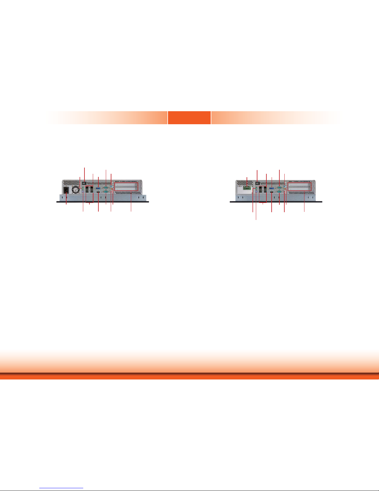
Bottom View - TPC150/TPC170/TPC190-SB
Power Switch
Press to power-on or power-off the system.
HDMI Port
Use to connect an HDMI device.
DVI-I Port
Used to connect a DVI device.
COM Ports
Used to connect serial devices.
USB Ports
Used to connect USB 2.0/1.1 devices.
LAN Ports
Used to connect the system to a local area network.
Line-out
Used to connect to a speaker.
Line-in
Used to connect any audio devices such as Hi-fi set, CD player, tape player, AM/FM radio tuner,
synthesizer, etc
.
Mic-in
Used to connect an external microphone.
PS/2 KB/Mouse
Used to connect a PS/2 keyboard and a PS/2 mouse.
Line-in
Mic-in
Line-out
COM 2
COM 1
PS/2 KB
PS/2 Mouse
USB 2.0
Power Switch
LAN
DVI-I
HDMI
AC power
Expansion slots
Line-in
Mic-in
Line-out
COM 2
COM 1
PS/2 KB
PS/2 Mouse
USB 2.0
Power Switch
LAN
DVI-I
HDMI
24V DC-in
Expansion slots
Page 14
www.dfi .com
14
Chapter 1 Introduction
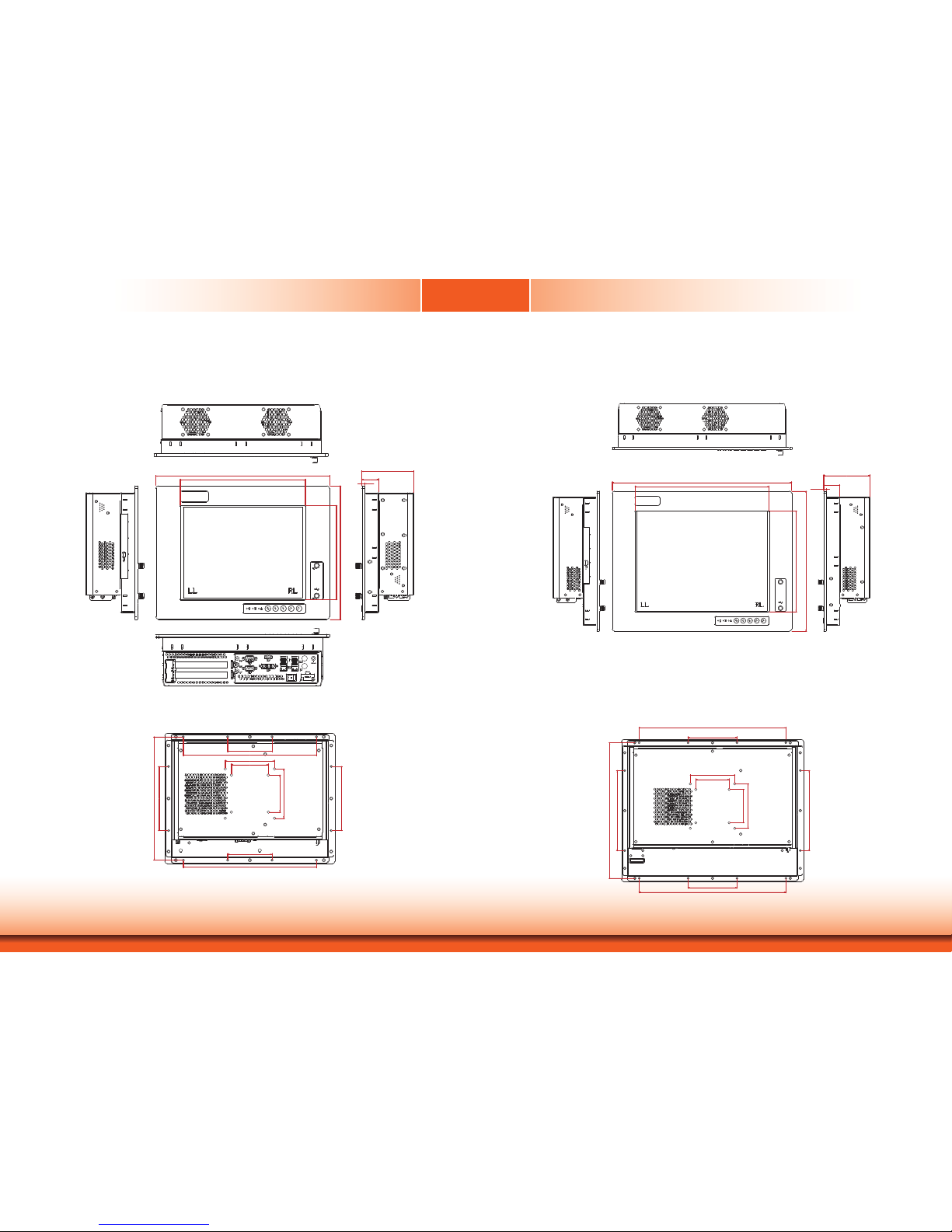
Mechanical Dimensions
TPC121
TPC150
Chapter 1
345.00
248.50
186.50
265.00
6.00
103.00
34.00
Bottom View
Right ViewLeft View
Top View
Front View
130.00
130.00
250.00
90.00
270.00
75.00
100.00
75.00
100.00
90.00
270.00
Rear View
306.00
410.00
305 00
6.00
37.00
106.00
230.00
320.00
Right ViewLeft View
Top View
Front View
110.00
330.00
75.00
100.00
75.00
100.00
110.00
330.00
180.00
305.00
180.00
Rear View
Page 15
www.dfi .com
15
Chapter 1 Introduction
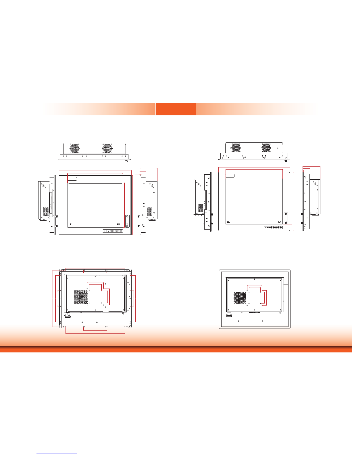
TPC170
Chapter 1
6.00
37.00
106.00
363.00
272.80
339.50
443.78
Right ViewLeft View
Top View
Front View
285.75
348.00
95.25
95.25
144.00
364.00
75.00
100.00
75.00
100.00
144.00
364.00
285.75
Rear View
TPC190-SB
472.00
377.50
116.00
47.00
6.00
300.80
391.00
Right ViewLeft View
Top View
Front View
Rear View
100.00
75.00
100.00
75.00
Page 16
www.dfi .com
16
Chapter 1 Introduction
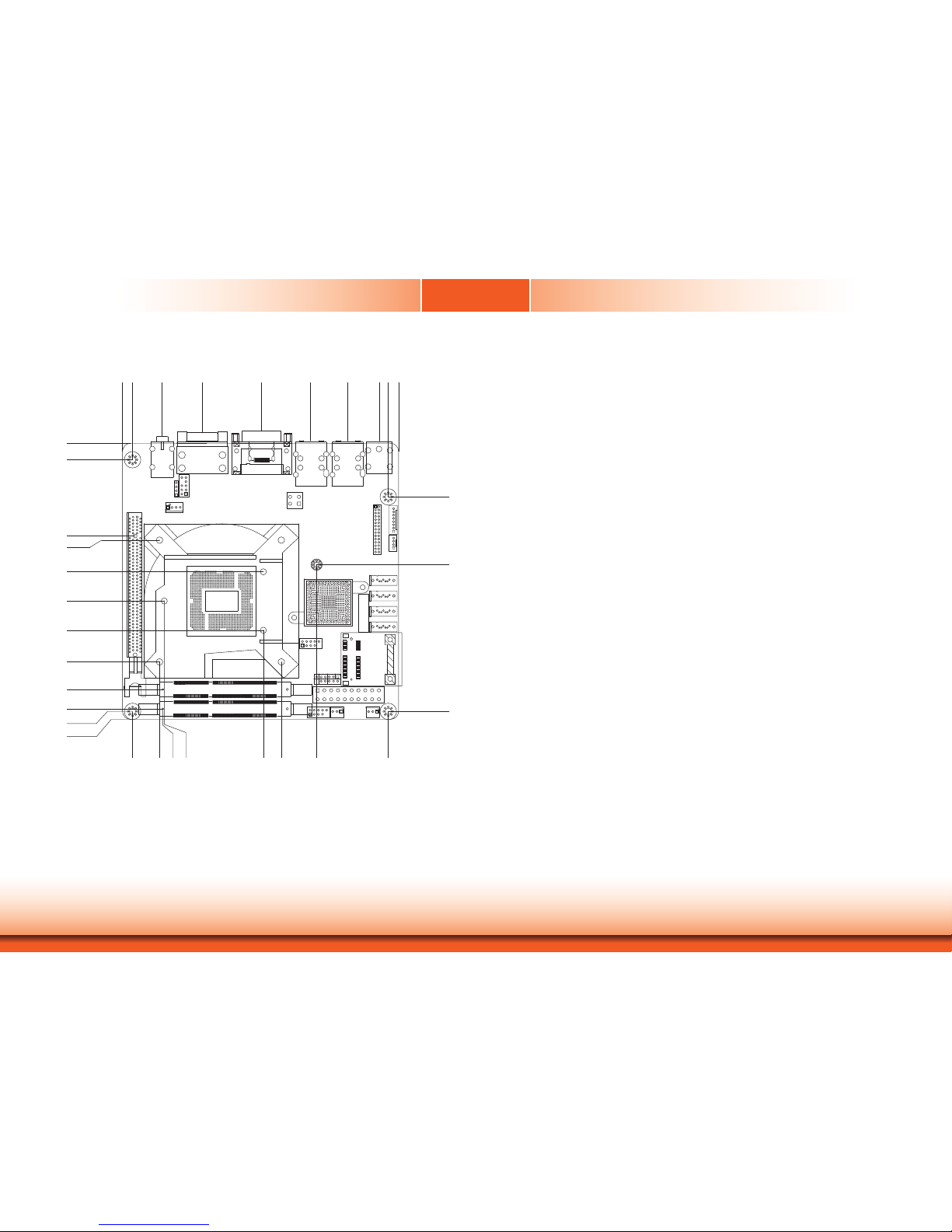
Motherboard Dimension
0.00
0.00
6.17
18.23
42.88
79.42
109.25
132.41
151.79
157.48
163.83
10.16
46.94
49.47
68.97
86.97
104.97
124.47
141.39
153.34
154.94
159.84
0.00
18.71
16.62
19.53
80.55
91.63
157.48
154.9
4
64.59
22.8
6
113.35
Page 17

www.dfi .com
17
Chapter 2 Getting Started
Chapter 2
Preparing the System
Before you start using the system, you need the following items:
• SATA hard drive
• AC power adapter
• PS/2 or USB keyboard
• PS/2 or USB mouse
• CD-ROM drive (for installing software/drivers)
• Screwdriver
• Memory module (optional)
Installing Devices
The following are devices that can be installed in the TPC121/150/170 system.
• Memory module
• SATA hard drive
• Mini PCIe card
Configuring the BIOS
To get you started, you may need to change configurations such as the date, time and the
type of hard disk drive.
1. Power-on the system.
2. After the memory test, the message “Press DEL to run setup” will appear on the screen.
Press the Delete key to enter the AMI BIOS setup utility.
Installing the Operating System
Most operating system software are provided in a CD therefore you need to install a CD-ROM
drive in order to use the CD.
Make sure a 2.5” SATA drive is already installed.
1. Refer to the following chapters for information on connecting a CD-ROM drive and installing a SATA drive.
2. Refer to your operating system manual for instructions on installing the operating system.
Installing the Drivers
The system package includes a CD disk. The CD includes drivers that must be installed to provide the best system performance. Refer to the Supported Software chapter for instructions on
installing the drivers.
Chapter 2 - Getting Started
Page 18
Chapter 3
Chapter 3
www.dfi .com
18
Chapter 3 Installing Devices
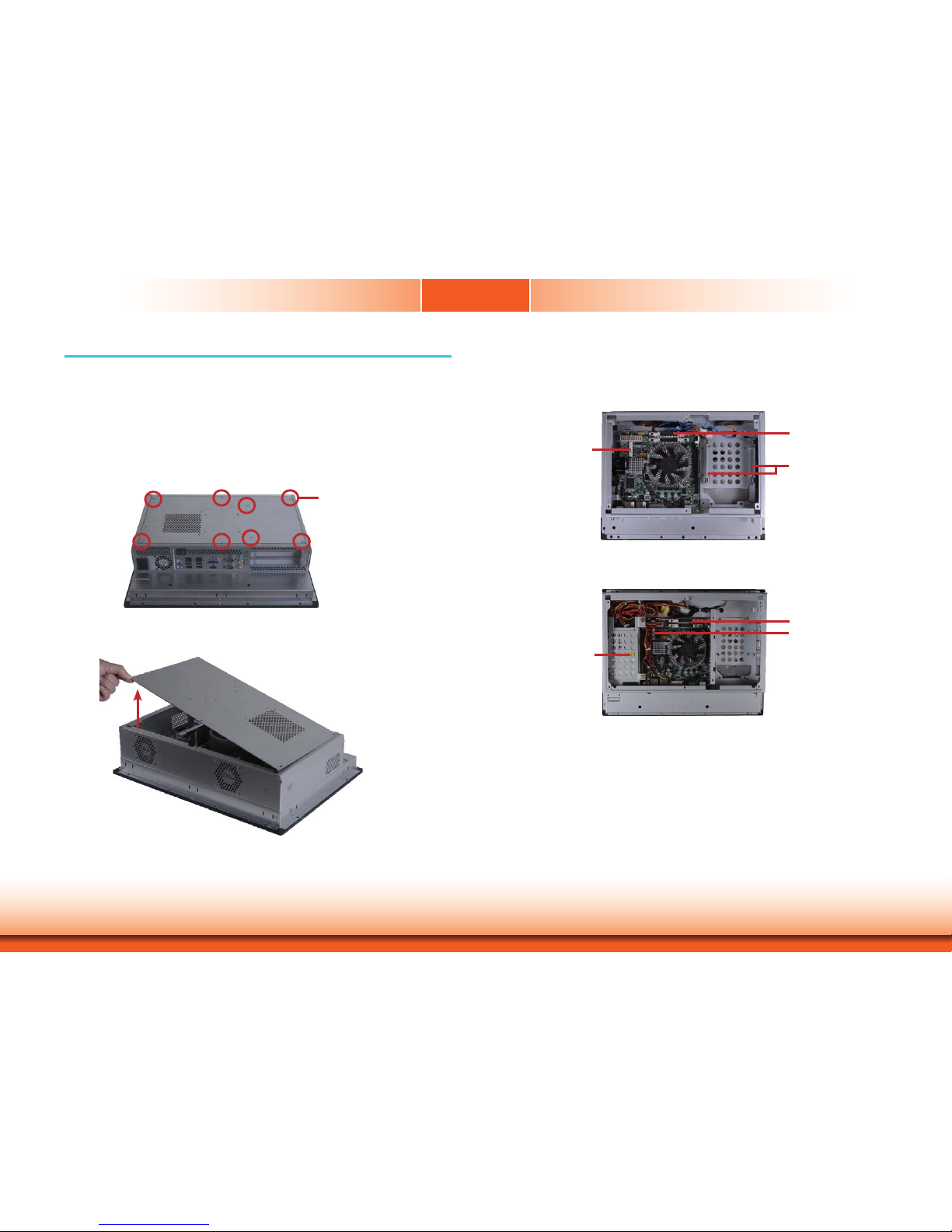
Chapter 3 - Installing Devices
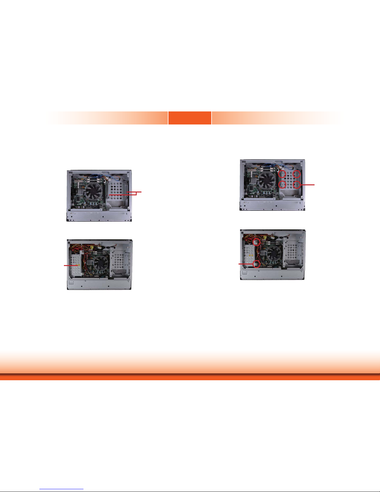
1. Make sure the system and all other peripheral devices connected to it has been powered-
off.
2. Disconnect all power cords and cables.
3. The 8 mounting screws on the rear side of the system are used to secure the cover to the
chassis. Remove these screws and then put them in a safe place for later use.
Removing the Chassis Cover
Mounting Screw
4. After removing the mounting screws, lift the cover up.
5. The memory socket, expansion slots, Mini PCIe slot and SATA drive bay are readily accessible after removing the chassis cover.
Lift the Cover Upward
SODIMM socket
SATA drive bay
Mini PCIe Slot
TPC121/TPC190-SB
TPC150/TPC170
SODIMM socket
Mini PCIe slot
SATA drive bay
Page 19
Chapter 3
Chapter 3
www.dfi .com
19
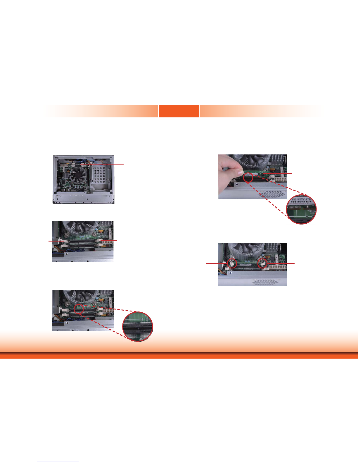
Chapter 3 Installing Devices
4. Grasping the module by its edges, position the module above the socket with the notch in the
socket aligned with the key on the module. Apply fi rm even pressure to each end of the module
until it slips down into the socket. The contact fi ngers on the edge of the module will almost
completely disappear inside the socket.
SODIMM
3. Note the key on the socket. The key ensures the module can be plugged into the socket in only
one direction.
SODIMM socket
1. Locate the DIMM socket on the system board.
Installing an SODIMM
2. Push the ejector tabs which are at the ends of the socket at the side.
Ejector tab
Ejector tab
5. Push the module down until the clips at each end of the socket lock into position. You will hear
a distinctive “click”, indicating the module is correctly locked into position.
Clip Clip
Page 20
Chapter 3
Chapter 3
www.dfi .com
20
Chapter 3 Installing Devices
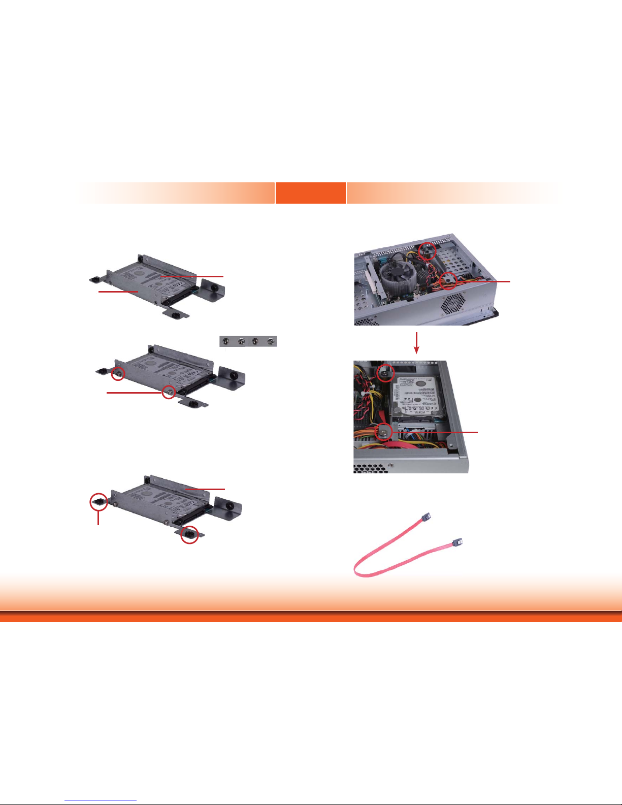
2. Remove the mounting screws that secure the HDD bracket to the drive bay.
Installing a SATA Drive
1. Locate the SATA drive bay in the chassis.
SATA drive bay
TPC150/TPC170
SATA drive bay
Mounting Screw
TPC150/TPC170
Mounting Screw
TPC121/TPC190-SB
TPC121/TPC190-SB
Page 21
Chapter 3
Chapter 3
www.dfi .com
21
Chapter 3 Installing Devices
3. Align the mounting holes of the SATA drive with the mounting holes on the HDD bracket and
then use the provided mounting screws to secure the drive in place.
HDD bracket
4. Place the SATA drive (with HDD bracket) back into place. Align the mounting holes on the
HDD bracket with the mounting holes on the SATA drive bay and then use the provided mounting
screws to secure the drive in place.
Mounting screws
e
t
SATA drive
ounti
n
Mounting screw
Mounting hole
HDD bracket
5. Connect one end to the SATA data connector on the SATA drive and the other end to the SATA
data connector on the system board.
Mounting screw
Mounting hole
Page 22
Chapter 3
Chapter 3
www.dfi .com
22
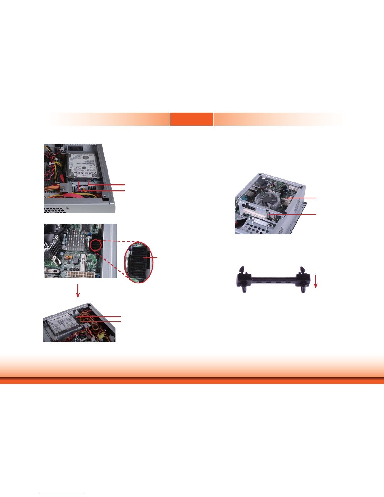
Chapter 3 Installing Devices
SATA data connector
SATA data
connector
SATA data connector
SATA power connector
SATA power connector
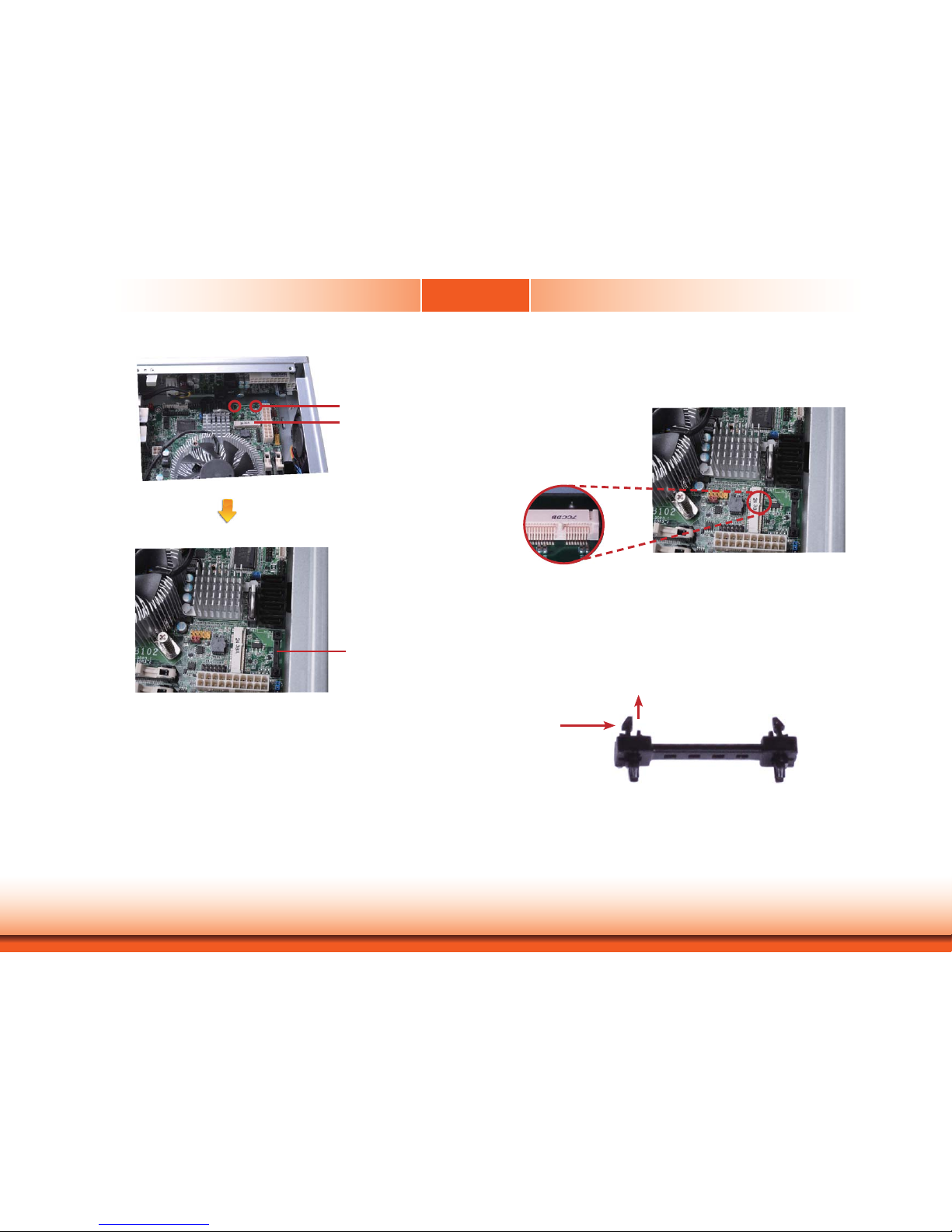
Installing a Mini PCIe Card
Latch
1. Locate the two Mini PCIe slots on the chassis.
Mini PCIe slot
Mini PCIe slot
2. The latch is used to lock the Mini PCIe card into position. Insert the latch into the mounting
holes and then push the latch down until the clips at each end of the latch lock into position. You
will hear a distinctive "click", indicating the latch is correctly locked into position.
Latch
Page 23
Chapter 3
Chapter 3
www.dfi .com
23
Chapter 3 Installing Devices
Latch
3. The system board is equipped with a Mini PCIe slot. The Mini PCIe slot supports half length
Mini PCIe card. Note the key on the slot. The key ensures the Mini PCIe card can be plugged into
the slot in only one direction.
If you want to move the latch in order to use the desired card, please follow below steps:
1. Remove the clips at each end of the latch once at a time.
2. Press the clips to the center of the latch and pull it up.
3. Pull the clips up and remove the latch.
Latch
Pull up
Press to
the center
Mini PCIe slot
Mounting hole
Removing the Latch
Page 24

Chapter 3
Chapter 3
www.dfi .com
24
Chapter 3 Installing Devices
1. Grasping the Mini PCIe card by its edges, align the card into the slot at an approximately 30
degrees angle. Apply fi rm even pressure to each end of the card until it slips down into the slot.
The contact fi ngers on the edge of the card will almost completely disappear inside the slot.
2. Push the Mini PCIe card down until the clips at each end of the latch lock into position. You will
hear a distinctive “click”, indicating the card is correctly locked into position.
Clip
Clip
Installing the Mini PCIe Card
Mounting screw
Bracket
2. Remove these mounting screws and brackets, and then put them in a safe place for later use.
3. Insert the Expansion card with a bracket into the slot that is on the riser card. Replace the
screw you removed in step 2 to secure the bracket in place.
1. The PCI and PCIe x1 slots on the riser card are used to install the expansion cards. To install
the expansion cards, you need to remove the mounting screws that secure the brackets to the
chassis then remove the brackets.
PCI
PCIe x1
Expansion card
Note:
The Expansion card used in the illustration above may not resemble the actual card.
These illustrations are for reference only.
Installing the PCI and PCIe x1 Expansion Cards
Page 25
Chapter 3
Chapter 3
www.dfi .com
25
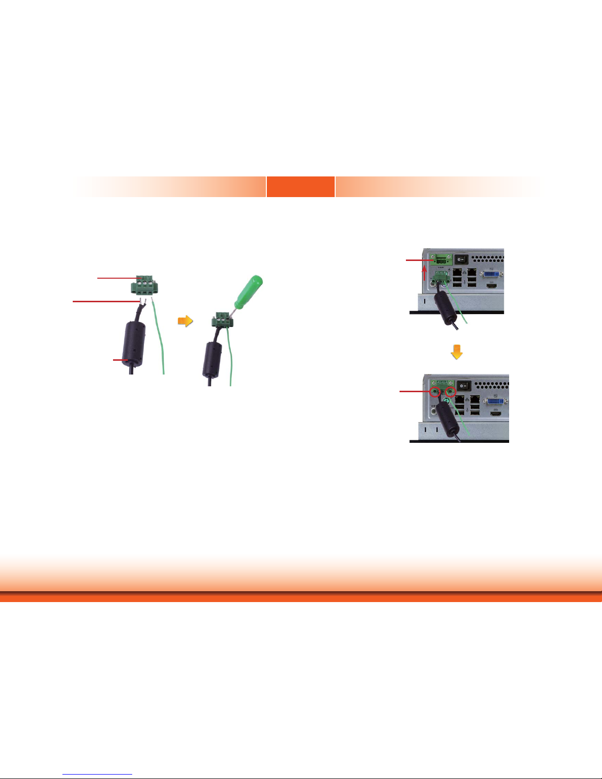
Chapter 3 Installing Devices
1. Insert the cable end of the power adaptor to the terminal block. To fi rmly fi x the cable into the
terminal block, use a screwdriver to clamp down the wires to the screw that is in the terminal
block.
Terminal block
Wire
Power adapter cable
2. Plug the terminal block into the DC-in connector and then tighten the screws to secure the
terminal block in place.
DC-in connector
Screws
Connecting Cables to Terminal Blocks
Page 26

Chapter 4
26
www.dfi .comChapter 4 Jumper Settings
Clear CMOS
If you encounter the following,
a) CMOS data becomes corrupted.
b) You forgot the supervisor or user password.
you can reconfigure the system with the default values stored in the ROM BIOS.
To load the default values stored in the ROM BIOS, please follow the steps below.
1. Power-off the system and unplug the power cord.
2. Set JP9 pins 2 and 3 to On. Wait for a few seconds and set JP9 back to its default setting,
pins 1 and 2 On.
3. Now plug the power cord and power-on the system.
JP9
2-3 On:
Clear CMOS Data
1-2 On: Normal
(default)
3
1
2
3
1
2
JP2 is used to select the power of the PS/2 keyboard and PS/2 mouse ports. Selecting +5V_
standby will allow you to use the PS/2 keyboard or PS/2 mouse to wake up the system.
2-3 On:
+5V_standby
1-2 On: +5V
(default)
PS/2 Power Select
3
1
2
3
1
2
JP2
Important:
The +5VSB power source of your power supply must support ≥720mA.
Chapter 4 - Jumper Settings
Page 27

Chapter 4
27
www.dfi .comChapter 4 Jumper Settings
These jumpers are used to select the power of the USB ports. Selecting +5V_standby will allow you to use a USB device to wake up the system.
USB Power Select
USB 0-1/8-9
(JP4)
1
3
2
1
3
2
USB 2-3/10-11
(JP7)
2-3 On:
+5V_standby
1-2 On: +5V
(default)
1
3
2
1
3
2
2-3 On:
+5V_standby
1-2 On: +5V
(default)
Important:
If you are using the Wake-On-USB Keyboard/Mouse function for 2 USB ports, the
+5V_standby power source of your power supply must support ≥1.5A. For 3 or more
USB ports, the +5V_standby power source of your power supply must support ≥2A.
Power-on Select
To power-on via WOL after G3:
1. Set JP8 pins 2 and 3 to On.
2. Set the “After G3” field to Power Off/WOL.
3. Set the “GbE Wake Up From S5” to Enabled.
The BIOS fields are in the “South Bridge Configuration” submenu (Chipset menu) of the AMI
BIOS utility.
To power-on via AC Power:
1. Set JP8 pins 2 and 3 to On.
2. Set the “After G3” field to Power On.
1-2 On:
Power-on via power button
(default)
2-3 On:
Power-on via AC power; or
Power-on via WOL after G3
JP8
312
312
Page 28

Chapter 4
28
www.dfi .comChapter 4 Jumper Settings
COM 1 RS232/RS422/RS485 Select
JP1 (for COM 1) is used to configure the COM port to RS232, RS422 (Full Duplex) or RS485.
The pin function of the COM ports will vary according to the jumper’s setting.
JP1
5-6 On: RS485
6
42
531
JP1
RS232
RS422
Full Duplex
RS485
COM 1
DCD-
TD
RD
DTR-
GND
1
2345
RTS-
RI-
DSR-
CTS-
6789
642
531
1-2 On: RS232
(default)
3-4 On: RS422
Full Duplex
6
42
531
RXD+
TXD+
RXD-
TXD-
N.C.
12345
6789
N.C.
N.C.
N.C.
N.C.
DATA+
DATA-
N.C.
N.C.
N.C.
N.C.
6789
12345
N.C.
N.C.
N.C.
COM 1 Signal Select
JP3
1-3 On: Pin-9
is RI (default)
JP3 (for COM 1) is used to configure pin 1 and pin 9 signal of the COM port. The pin function
of the COM ports will vary according to the jumper’s setting.
6
42
531
642
531
3-5 On: Pin-9
is VCC (+5V)
642
531
642
531
2-4 On: Pin-1
is DCD (default)
4-6 On: Pin-1
is VCC12 (+12V)
Page 29

Chapter 4
29
www.dfi .comChapter 4 Jumper Settings
JP5
Front Audio or Audio Amplifier Select
JP5 is used to configure front audio or audio amplifier select.
1-3, 2-4 On:
Front audio
(default)
6
4
2
5
3
1
6
4
2
5
3
1
3-5, 4-6 On:
Audio Amplifier
Page 30

Chapter 5
30
www.dfi .comChapter 6 Ports and Connectors
Chapter 5 - Ports and Connectors
Front Panel I/O Port
USB
The front panel I/O port consists of the following:
• 2 USB ports
USB Ports
USB allows data exchange between your computer and a wide range of simultaneously accessible external Plug and Play peripherals.
The system board is equipped with 2 USB 2.0/1.1 ports.
• BIOS Setting
Configure the onboard USB in the Advanced menu (“USB Configuration” submenu) of the
BIOS. Refer to chapter 7 for more information.
Important:
If you are using the Wake-On-USB Keyboard/Mouse function for 2 USB ports, the
+5V_standby power source of your power supply must support ≥1.5A. For 3 or more
USB ports, the +5V_standby power source of your power supply must support ≥2A.
Wake-On-USB Keyboard/Mouse
The Wake-On-USB Keyboard/Mouse function allows you to use a USB keyboard or USB mouse
to wake up a system from the S3 (STR - Suspend To RAM) state. To use this function:
• Jumper Setting
JP6 must be set to “2-3 On: +5V_standby”. Refer to “USB Power Select” in this chapter for
more information.
Page 31

Chapter 5
31
www.dfi .comChapter 6 Ports and Connectors
Bottom Panel I/O Ports
The bottom panel I/O ports consist of the following:
• 1 PS/2 Keyboard port
• 1 PS/2 Mouse port
• 2 LAN ports
• 4 USB 2.0 ports
• 1 DVI port
• 1 HDMI port
• 1 RS232/422/485 COM port
• 1 RS232 COM port
• 1 Line-in jack
• 1 Line-out jack
• 1 Mic-in jack
Line-in
Mic-in
Line-out
COM 2
COM 1
PS/2 KB
PS/2 Mouse
USB 2.0
LAN
DVI-I
HDMI
PS/2 Mouse and PS/2 Keyboard Ports
PS/2 Mouse
PS/2 K/B
These ports are used to connect a PS/2 mouse and a PS/2 keyboard. The PS/2 mouse port
uses IRQ12.
Wake-On-PS/2 Keyboard/Mouse
The Wake-On-PS/2 Keyboard/Mouse function allows you to use the PS/2 keyboard or PS/2
mouse to power-on the system. To use this function:
• Jumper Setting
JP2 must be set to “2-3 On: +5V_standby”. Refer to “PS/2 Power Select” in this chapter for
more information
.
• BIOS Setting
Configure the PS/2 keyboard/mouse wake up function in the Advanced menu (“ACPI Power
Management Configuration” submenu) of the BIOS. Refer to chapter 7 for more information.
Important:
The +5V_standby power source of your power supply must support ≥720mA.
Page 32

Chapter 5
32
www.dfi .comChapter 6 Ports and Connectors
RJ45 LAN Ports
The LAN ports allow the system board to connect to a local area network by means of a network hub.
BIOS Setting
Configure the onboard LAN in the Chipset menu (“South Bridge Configuration” submenu) of
the BIOS. Refer to chapter 7 for more information.
Driver Installation
Install the LAN drivers. Refer to chapter 8 for more information.
LAN 1
Features
• Intel W82579LM Gigabit Ethernet controller
• Intel W82574L PCI Express Gigabit Ethernet controller
LAN 2
USB Ports
USB allows data exchange between your computer and a wide range of simultaneously accessible external Plug and Play peripherals.
The system board is equipped with four onboard USB 2.0/1.1 ports (USB 0-1/ 8-9). The two
10-pin connectors allow you to connect 4 additional USB 2.0/1.1 ports (USB 2-3/ 10-11). The
additional USB ports may be mounted on a card-edge bracket. Install the card-edge bracket
to an available slot at the rear of the system chassis and then insert the USB port cables to a
connector.
BIOS Setting
Configure the onboard USB in the Advanced menu (“USB Configuration” submenu) of the
BIOS. Refer to chapter 7 for more information.
Driver Installation
You may need to install the proper drivers in your operating system to use the USB device.
Refer to your operating system’s manual or documentation for more information.
USB 10-11
USB 2-3
10
VCC
-Data
+Data
GND
Key
VCC
-Data
+Data
GND
N. C.
9
1
2
USB 2.0
USB 1
USB 0
USB 8
USB 9
USB 2.0
Page 33

Chapter 5
33
www.dfi .comChapter 6 Ports and Connectors
HDMI
Graphics Interfaces
DVI-I
The display ports consist of the following:
• HDMI
• DVI-I port
HDMI Port
The HDMI port which carries both digital audio and video signals is used to connect a LCD
monitor or digital TV that has the HDMI port.
DVI-I Port
The DVI-I port is used to connect an LCD monitor.
Connect the display device’s cable connector to the DVI-I port. After you plug the cable connector into the port, gently tighten the cable screws to hold the connector in place.
BIOS Setting
Configure the display device in the Chipset menu (“North Bridge Configuration” submenu) of
the BIOS. Refer to chapter 7 for more information.
Important:
If you are using the Wake-On-USB Keyboard/Mouse function for 2 USB ports, the
+5V_standby power source of your power supply must support ≥1.5A. For 3 or more
USB ports, the +5V_standby power source of your power supply must support ≥2A.
Wake-On-USB Keyboard/Mouse
The Wake-On-USB Keyboard/Mouse function allows you to use a USB keyboard or USB mouse
to wake up a system from the S3 (STR - Suspend To RAM) state. To use this function:
• Jumper Setting
JP6 must be set to “2-3 On: +5V_standby”. Refer to “USB Power Select” in this chapter for
more information.
Page 34

Chapter 5
34
www.dfi .comChapter 6 Ports and Connectors
COM (Serial) Ports
The pin function of COM 1 port will vary according to JP1’s setting. Refer to “COM1 RS232/
RS422/RS485 Select” in this chapter for more information.
The serial ports are asynchronous communication ports with 16C550A-compatible UARTs that
can be used with modems, serial printers, remote display terminals, and other serial devices.
Connecting External Serial Ports
Your COM port may come mounted on a card-edge bracket. Install the card-edge bracket to
an available slot at the rear of the system chassis then insert the serial port cable to the COM
connector. Make sure the colored stripe on the ribbon cable is aligned with pin 1 of the COM
connector.
BIOS Setting
Configure the serial ports in the Advanced menu (“Super IO Configuration” submenu) of the
BIOS. Refer to chapter 7 for more information.
COM 1:
RS232/422/485
Audio
Rear Audio
The system board is equipped with 3 audio jacks. A jack is a one-hole connecting interface for
inserting a plug.
• Mic-in Jack (Pink)
This jack is used to connect an external microphone.
• Line-in Jack (Light Blue)
This jack is used to connect any audio devices such as Hi-fi set, CD player, tape player,
AM/FM radio tuner, synthesizer, etc.
• Line-out Jack (Lime)
This jack is used to connect a headphone or external speakers.
Front Audio
The front audio connector allows you to connect to the second line-out and mic-in jacks that
are at the front panel of your system.
Line-out
Line-in
Mic-in
Rear audio
Front audio
COM 2: RS232
10
Mic2-L
Line2-R
Front_IO_Sense
GND
Presence Signal
Key
9
1
Mic2-JD
Line2-JD
2
Mic2-R
Line2-L
Page 35

Chapter 5
35
www.dfi .comChapter 6 Ports and Connectors
BIOS Setting
Configure the onboard audio in the Chipset menu (“South Bridge” submenu) of the BIOS.
Refer to chapter 3 for more information.
Driver Installation
Install the audio driver. Refer to chapter 8 for more information.
I/O Connectors
SATA (Serial ATA) Connectors
SATA 2.0 3Gb/s
• Serial ATA ports
- 4 SATA 2.0 ports with data transfer rate up to 3Gb/s
The Serial ATA connectors are used to connect Serial ATA devices. Connect one end of the Serial ATA cable to a SATA connector and the other end to your Serial ATA device.
BIOS Setting
Configure the Serial ATA drives in the Advanced menu (“SATA Configuration” submenu) of the
BIOS. Refer to chapter 7 for more information.
7
RXN
GND
TXP
TXN
GND
1
RXP
GND
Features
SATA 0
SATA 1
SATA 4
SATA 5
Page 36

Chapter 5
36
www.dfi .comChapter 6 Ports and Connectors
The 8-bit Digital I/O connector provides powering-on function to external devices that are connected to these connectors.
14
+12V
Ground
5VSB
+5V
Digital I/O power
Digital I/O
Digital I/O Connector
Digital I/O Power Connector
Digital I/O Connector
Pins Function
1
DIO7
2
DIO6
3
DIO5
4
DIO4
5
DIO3
6
DIO2
7
DIO1
8
DIO0
18
The audio amplifier connector which has amplifying feature is used to connect external speakers. Use the same signal cable to connect with an external speaker.
Audio Amplifier
Audio Amplifier Connector
Out L+
Out R+
Out L-
Out R-
14
Page 37

Chapter 5
37
www.dfi .comChapter 6 Ports and Connectors
4
1
Sense
Power
Ground
Speed Control
Cooling Fan Connectors
The fan connectors are used to connect cooling fans. The cooling fans will provide adequate
airflow throughout the chassis to prevent overheating the CPU and system board components.
BIOS Setting
The Advanced menu (“PC Health Configuration” submenu) of the BIOS will display the current
speed of the cooling fans. Refer to chapter 7 for more information.
System_fan 1
1
3
Sense
Power
Ground
CPU fan
Chassis Intrusion Connector
The board supports the chassis intrusion detection function. Connect the chassis intrusion
sensor cable from the chassis to this connector. When the system’s power is on and a chassis
intrusion occurred, an alarm will sound. When the system’s power is off and a chassis intrusion
occurred, the alarm will sound only when the system restarts.
MyGuard Hardware Monitor
Install the “MyGuard Hardware Monitor” utility. By default, the chassis intrusion detection function is disabled. When enabled, a warning message will appear when the chassis is open. The
utility can also be configured so that a beeping alarm will sound when the chassis is open. Refer to the “MyGuard Hardware Monitor” section in chapter 8 for more information.
12
Ground
Signal
1
3
Sense
Power
Ground
System_fan 2
Page 38

Chapter 5
38
www.dfi .comChapter 6 Ports and Connectors
Power Connectors
Use a power supply that complies with the ATX12V Power Supply Design Guide Version 1.1.
An ATX12V power supply unit has a standard 20-pin ATX main power connector that must be
inserted into the 20-pin connector. The 4-pin +12V power connector enables the delivery of
more +12VDC current to the processor’s Voltage Regulator Module (VRM).
The power connectors from the power supply unit are designed to fit the 20-pin and 4-pin
connectors in only one orientation. Make sure to find the proper orientation before plugging
the connectors.
The system board requires a minimum of 300 Watt power supply to operate. Your system
configuration (CPU power, amount of memory, add-in cards, peripherals, etc.) may exceed the
minimum power requirement. To ensure that adequate power is provided, we strongly recommend that you use a minimum of 400 Watt (or greater) power supply.
Important:
Insufficient power supplied to the system may result in instability or the add-in boards
and peripherals not functioning properly. Calculating the system’s approximate power
usage is important to ensure that the power supply meets the system’s consumption
requirements.
1
3
2
4
Ground
Ground
+12V
+12V
ATX power
11
10 20
1
3.3V
3.3V
GND
+5V
GND
+5V
GND
PW-OK
5VSB
+12V
3.3V
-12V
GND
PS-ON
GND
GND
GND
-5V
+5V
+5V
ATX 12V
Standby Power LED
Standby Power LED
This LED will lit red when the system is in the standby mode. It indicates that there is power
on the system board. Power-off the PC and then unplug the power cord prior to installing any
devices. Failure to do so will cause severe damage to the motherboard and components.
Page 39

Chapter 5
39
www.dfi .comChapter 6 Ports and Connectors
Front Panel Connector
HDD-LED - HDD LED
This LED will light when the hard drive is being accessed.
RESET SW - Reset Switch
This switch allows you to reboot without having to power off the system.
PWR-BTN - Power Switch
This switch is used to power on or off the system.
PWR-LED - Power/Standby LED
When the system’s power is on, this LED will light. When the system is in the S1 (POS - Power
On Suspend) state, it will blink every second. When the system is in the S3 (STR - Suspend To
RAM) state, it will blink every 4 seconds.
HDD-LED
RESET-SW
PWR-LED
PWR-BTN
12
11
21
Pin Pin Assignment Pin Pin Assignment
HDD-LED
3 HDD Power
PWR-LED
2 LED Power
5 Signal 4 LED Power
RESET SW
7 Ground 6 Signal
9 RST Signal
PWR-BTN
8 Ground
11 N.C. 10 Signal
Expansion Slots
PCI Express x16 Slot
The PCI Express x16 slot is an interface for the X100-3PE2 riser card. The X100-3PE2 features:
• 1 PCIe x1 slot
• 1 PCI slot
• 1 Mini PCIe slot
Mini PCI Express Slot
The Mini PCI Express slot on the system board is used to install a half size Mini PCIe card
such as network cards or other cards that comply to the mini PCI Express specifications into
the mini PCI Express slot.
PCI Express x16
Mini PCI Express
Note:
The Mini PCIe slot on the system board and on the X100-3PE2 riser card can be used
at the same time.
Page 40

Chapter 5
40
www.dfi .comChapter 6 Ports and Connectors
The lithium ion battery powers the real-time clock and CMOS memory. It is an auxiliary source
of power when the main power is shut off.
Safety Measures
• Danger of explosion if battery incorrectly replaced.
• Replace only with the same or equivalent type recommend by the manufacturer.
• Dispose of used batteries according to local ordinance
.
Battery
Battery
SDVO Connector
SDVO
2
1
30
29
The SDVO connector is used to connect the optional SDVO-LVDS daughterboard.
Pins Pin Assignment Pins Pin Assignment
1
Ground 2 DPB_AUXP
3
DPB_LANE0_P 4 DPB_AUXN
5
DPB_LANE0_N 6 SDVO_STALLP
7
Ground 8 SDVO_STALLN
9
DPB_LANE1_P 10 SDVO_INTP
11
DPB_LANE1_N 12 SDVO_INTN
13
Ground 14 PCIE_RST
15
DPB_LANE2_P 16 DPB_CTRLCLK
17
DPB_LANE2_N 18 DPB_CTRLDATA
19
Ground 20 DPB_HPD
21
DPB_LANE3_P 22 GPIO15/SMBCLK
23
DPB_LANE3_N 24 GPIO27/SMBDATA/L_BKLTCTL
25
+3V3 26 +3V3
27
+5V 28 +5V
29
+12V 30 +12V
Page 41

Chapter 5
41
www.dfi .comChapter 6 Ports and Connectors
SDVO-LVDS Daughterboard (optional)
Features
• Chrontel CH7308B
• Supports 18/24-bit 1600x1200 LVDS panel (default 1280x1024)
• 1 LVDS LCD panel connector
• 1 LCD/Inverter power connector
• SDVO interface
• Supports dimming control via hot keys or AP tool
Dimensions
• 45mm (1.77") x 38mm (1.49")
JP8
3-4 On: +5V
1
3
5
2
4
6
1
3
5
2
4
6
5-6 On: +3.3V
(default)
1-2 On: +12V
1
3
5
2
4
6
JP8 is used to select the power supplied to the LCD panel.
Power Select for the LCD Panel
Important:
Before powering-on the system, make sure JP8’s setting matches the LCD panel’s
specification. Selecting the incorrect voltage will seriously damage the LCD panel.
Page 42

Chapter 5
42
www.dfi .comChapter 6 Ports and Connectors
LVDS LCD Panel and LCD Inverter Power Connectors
LVDS LCD panel
LCD/Inverter
power
81
2
1
40
39
The system board allows you to connect a LCD Display Panel by means of the LVDS LCD panel
connector and the LCD/Inverter power connector. These connectors transmit video signals and
power from the system board to the LCD Display Panel.
Pins Function Pins Function
1
GND
2
GND
3
LVDS_Out3+
4
LVDS_Out7+
5
LVDS_Out3-
6
LVDS_Out7-
7
GND
8
GND
9
LVDS_Out2+
10
LVDS_Out6+
11
LVDS_Out2-
12
LVDS_Out6-
13
GND
14
GND
15
LVDS_Out1+
16
LVDS_Out5+
17
LVDS_Out1-
18
LVDS_Out5-
19
GND
20
GND
21
LVDS_Out0+
22
LVDS_Out4+
23
LVDS_Out0-
24
LVDS_Out4-
25
GND
26
GND
27
LVDS_CLK1+
28
LVDS_CLK2+
29
LVDS_CLK1-
30
LVDS_CLK2-
31
GND
32
GND
33
LVDS_DDCCLK
34
N.C.
35
LVDS_DDCDAA
36
N.C.
37
Panel Power
38
Panel Power
39
Panel Power
40
Panel Power
LVDS LCD Panel Connector
Page 43

Chapter 5
43
www.dfi .comChapter 6 Ports and Connectors
Installing the SDVO-LVDS Daughterboard onto the
Motherboard (optional)
1. The photo below shows the location of the mounting hole on the motherboard.
Mounting hole
2. Insert the provided mounting screw into the mounting hole - from the bottom through the
top of the motherboard.
Mounting screw
LCD/Inverter Power Connector
Pins Function
1
GND
2
GND
3
Panel Inverter Brightness Voltage Control
4
Panel Power
5
+3.3V
6
Panel Backlight On/Off Control
7
+12V
8
+12V
Important:
The motherboard used in this section is for reference purpose only and may not
resemble your motherboard. These illustrations are mainly to guide you on how to
install SDVO-LVDS onto the motherboard of your choice.
Mounting hole
Page 44

Chapter 5
44
www.dfi .comChapter 6 Ports and Connectors
3. While supporting the mounting screw at the bottom, from the top side of the board, fasten
a bolt into the screw.
Bolt
4. The SDVO connector is located at the bottom of the daughterboard. Grasping the daughterboard by its edges, position it on top of the motherboard’s SDVO connector with its
mounting holes aligned with the bolt on the motherboard. This will also align the SDVO
connector of the two boards to each other.
SDVO connector at the bottom side
of the daughterboard
SDVO connector on the
motherboard
5. Press the daughterboard down firmly until it is completely seated on the SDVO connector
of the motherboard.
Motherboard
Daughterboard
6. Use the provided mounting screw to secure the daughterboard to the motherboard.
Mounting screw
Page 45

Chapter 6
45
www.dfi .comChapter 6 Mounting Options
Wall Mount
The wall mount kit includes the following:
• 2 Wall mount brackets
• Bracket screws
Wall mount bracket 1 Wall mount bracket 2
1. Select a place on the wall where you will mount the Panel PC.
2. Use the provided mounting screws to attach “wall mount bracket 1” to the wall.
Wall mount bracket 1
Mounting screw
Wall mount bracket 2
4. Using the hooks on “bracket 2”, slide the Panel PC to “bracket 1”.
Wall mount bracket 2
Mounting screw
Wall mount bracket 1
3. Attach the other bracket (wall mount bracket 2) to the rear of the Panel PC.
Hooks
Chapter 6 - Mounting Options
Page 46

Chapter 6
46
www.dfi .comChapter 6 Mounting Options
Panel Mount
The panel mounting kit includes the following:
• 10 mounting clamps (TPC121 and TPC150)
• 12 mounting clamps (TPC170 and TPC190-SB)
241.00
321.00
1. Select a place on the panel where you will mount the Panel PC.
2. Cut out a shape on the panel that corresponds to the Panel PC’s rear dimensions.
TPC121
296.00
386.00
TPC150
339.00
420.00
TPC170
367
448
TPC190-SB
Page 47

Chapter 6
47
www.dfi .comChapter 6 Mounting Options
Slit for mounting the clamp
Mounting clamp
White plastic cap
6. The fi rst and second clamps must be positioned and secured diagonally prior to mounting the
rest of the clamps. Tighten the clamp’s screw using an electric screwdriver until the white plastic
cap touches the panel. Do not over tighten the screws to prevent damaging the Panel PC. The
illustration below shows all clamps properly mounted.
4. Slide the Panel PC through the hole until it is properly fi tted against the panel.
5. Position the mounting clamps along the rear edges of the Panel PC, fi tting them into the slits
that are around the Panel PC.
296.00
386.00
Note:
The maximum thickness of your panel’s opening should be 10 mm. Be sure to route
or trim down the thick wall to 10 mm or slightly less for the clamps to recess and
be compatible with your wall or enclosure.
3. Stick the poron foam on the rear panel.
Poron foam
Poron foam
Page 48

Chapter 7
48
www.dfi .comChapter 7 BIOS Setup
Chapter 7 - BIOS Setup
Overview
The BIOS is a program that takes care of the basic level of communication between the CPU
and peripherals. It contains codes for various advanced features found in this system board.
The BIOS allows you to configure the system and save the configuration in a battery-backed
CMOS so that the data retains even when the power is off. In general, the information stored
in the CMOS RAM of the EEPROM will stay unchanged unless a configuration change has been
made such as a hard drive replaced or a device added.
It is possible that the CMOS battery will fail causing CMOS data loss. If this happens, you need
to install a new CMOS battery and reconfigure the BIOS settings.
Default Configuration
Most of the configuration settings are either predefined according to the Load Optimal Defaults
settings which are stored in the BIOS or are automatically detected and configured without requiring any actions. There are a few settings that you may need to change depending on your
system configuration.
Entering the BIOS Setup Utility
The BIOS Setup Utility can only be operated from the keyboard and all commands are keyboard commands. The commands are available at the right side of each setup screen.
The BIOS Setup Utility does not require an operating system to run. After you power up the
system, the BIOS message appears on the screen and the memory count begins. After the
memory test, the message “Press DEL to run setup” will appear on the screen. If the message
disappears before you respond, restart the system or press the “Reset” button. You may also
restart the system by pressing the <Ctrl> <Alt> and <Del> keys simultaneously.
Legends
Scroll Bar
When a scroll bar appears to the right of the setup screen, it indicates that there are more
available fields not shown on the screen. Use the up and down arrow keys to scroll through all
the available fields.
Submenu
When ““ appears on the left of a particular field, it indicates that a submenu which contains
additional options are available for that field. To display the submenu, move the highlight to
that field and press <Enter>.
Keys Function
Right and Left arrows
Moves the highlight left or right to select a menu.
Up and Down arrows
Moves the hightlight up or down between submenu or fi elds.
<Esc>
Exit to the BIOS Setup Utility.
+ (plus key)
Scrolls forward through the values or options of the highlighted fi eld.
- (minus key)
Scrolls backward through the values or options of the highlighted
fi eld.
Tab
Select a fi eld.
<F1>
Displays General Help
<F4>
Saves and exits the Setup program.
<Enter>
Press <Enter> to enter the highlighted submenu.
Note:
The BIOS is constantly updated to improve the performance of the system board;
therefore the BIOS screens in this chapter may not appear the same as the actual
one. These screens are for reference purpose only.
Page 49

Chapter 7
49
www.dfi .comChapter 7 BIOS Setup
Main
The Main menu is the first screen that you will see when you enter the BIOS Setup Utility.
System Date
The date format is <day>, <month>, <date>, <year>. Day displays a day, from Sunday to Saturday. Month displays the month, from January to December. Date displays
the date, from 1 to 31. Year displays the year, from 1980 to 2099.
System Time
The time format is <hour>, <minute>, <second>. The time is based on the 24-hour
military-time clock. For example, 1 p.m. is 13:00:00. Hour displays hours from 00 to
23. Minute displays minutes from 00 to 59. Second displays seconds from 00 to 59.
AMI BIOS Setup Utility Advanced
The Advanced menu allows you to configure your system for basic operation. Some entries are
defaults required by the system board, while others, if enabled, will improve the performance
of your system or let you set some features according to your preference.
Choose the system default
language
Aptio Setup Utility - Copyright (C) 2011 American Megatrends, Inc.
Save & ExitChipset
Version 2.14.1219. Copyright (C) 2011 American Megatrends, Inc.
Select Screen
Select Item
Enter: Select
+/-: Change Opt.
F1: General Help
F2: Previous Values
F3: Optimized Defaults
F4: Save & Exit
ESC: Exit
BIOS Information
BIOS Vendor
Core Version
Compliency
Project Version
Build Date and Time
System Language
System Date
System Time
Access Level
American Megatrends
4.6.5.3
UEFI 2.3; PI 1.2
1APTC 0.20 x64
08/31/2012 15:48:35
[English]
[Fri 08/31/2012]
[16:29:48]
Administraor
Advanced
Boot Security
Main
Important:
Setting incorrect field values may cause the system to malfunction.
ACPI power management
confi guration
Aptio Setup Utility - Copyright (C) 2011 American Megatrends, Inc.
Version 2.14.1219. Copyright (C) 2011 American Megatrends, Inc.
ACPI Power Management Confi guration
PC Health Status
CPU Confi guration
SATA Confi guration
USB Confi guration
F71879 Super IO Confi guration
Network Stack
Save & ExitChipset Boot Security
Main
Advanced
Select Screen
Select Item
Enter: Select
+/-: Change Opt.
F1: General Help
F2: Previous Values
F3: Optimized Defaults
ESC: Exit
Page 50

Chapter 7
50
www.dfi .comChapter 7 BIOS Setup
ACPI Power Management Configuration
This section is used to configure the ACPI Power Management.
About resume by PME
(PCI, PCIE, LAN)
Aptio Setup Utility - Copyright (C) 2011 American Megatrends, Inc.
Version 2.14.1219. Copyright (C) 2011 American Megatrends, Inc.
ACPI Power Management Confi guration
ACPI Sleep State
Resume by PME
Resume by PS2 KB (S1, S3)
Resume by PS2 MS (S1, S3)
Resume by Ring
Resume by RTC Alarm
Advanced
[S1 (CPU Stop Clock)]
[Enabled]
[Disabled]
[Disabled]
[Disabled]
[Disabled]
ACPI Sleep State
Selects the highest ACPI sleep state the system will enter when the Suspend
button is pressed.
S1(POS) Enables the Power On Suspend function.
S3(STR) Enables the Suspend to RAM function.
Resume by PME
Enable this field to use the PME signal to wake up the system.
Resume by PS2 KB (S1, S3)
About resume by PS2 KB (S1, S3); Options are enabled or disabled.
Resume by PS2 MS (S1, S3)
About resume by PS2 MS (S1, S3); Options are enabled or disabled.
Resume by Ring
Enable this field to use the Ring signal to wake up the system.
Resume by RTC Alarm
When Enabled, the system uses the RTC to generate a wakeup event.
Select Screen
Select Item
Enter: Select
+/-: Change Opt.
F1: General Help
F2: Previous Values
F3: Optimized Defaults
ESC: Exit
PC Health Status
This section displays the SIO hardware health monitor.
Aptio Setup Utility - Copyright (C) 2011 American Megatrends, Inc.
Version 2.14.1219. Copyright (C) 2011 American Megatrends, Inc.
System Hardware Monitor
Smart Fan Function
Case Open Beep
CPU Temperature
System Temperature
CPU FAN Speed
System FAN Speed
System FAN2 Speed
VCore
+5.0V
+12V
VDIMM
+3.3V
VS5V
Advanced
[Disabled]
: +50 C
: +32 C
: 1045 RPM
: N/A
: N/A
: +0.976 V
: +4.920V
: +11.968V
: +1.536 V
: +3.224 V
: +5.032 V
Select Screen
Select Item
Enter: Select
+/-: Change Opt.
F1: General Help
F2: Previous Values
F3: Optimized Defaults
ESC: Exit
Aptio Setup Utility - Copyright (C) 2011 American Megatrends, Inc.
Version 2.14.1219. Copyright (C) 2011 American Megatrends, Inc.
CPU Smart Fan Control
Boundary 1
Boundary 2
Boundary 3
Boundary 4
Speed Count 1
Speed Count 2
Speed Count 3
Speed Count 4
Speed Count 5
System Smart Fan(1) Control
Boundary 1
Boundary 2
Boundary 3
Boundary 4
Speed Count 1
Speed Count 2
Speed Count 3
Speed Count 4
Speed Count 5
System Smart Fan(2) Control
Boundary 1
Boundary 2
Boundary 3
Boundary 4
Speed Count 1
Speed Count 2
Speed Count 3
Speed Count 4
Speed Count 5
Advanced
[Automatic]
60
50
40
30
100
75
50
40
30
[Automatic]
60
50
40
30
100
75
50
40
30
[Automatic]
60
50
40
30
100
75
50
40
30
Select Screen
Select Item
Enter: Select
+/-: Change Opt.
F1: General Help
F2: Previous Values
F3: Optimized Defaults
ESC: Exit
Smart Fan Function
CPU Smart Fan Control
When this feature is set to Automatic, the CPU’s fan speed will rotate according to the
CPU’s temperature. The higher the temperature, the faster the speed of rotation.
Smart Fan Function
Enable CPU SmartFan
Page 51

Chapter 7
51
www.dfi .comChapter 7 BIOS Setup
Boundary 1 to Boundary 4
The range is from 0-127.
Speed Count 1 to Speed Count 5
The range is from 1-100.
Case Open Beep
Set this fi eld to Enabled to allow the system to alert you of a chassis intrusion event.
CPU Configuration
This section is used to configure the CPU. It will also display the detected CPU information.
Enabled for Windows XP
and Linux (OS optimized
for Hyper-Threading
Technology) and Disabled
for other OS (OS not
optimized for
Hyper-Threading
Technology). When
Disabled only one thread
per enabled core is
enabled.
Aptio Setup Utility - Copyright (C) 2011 American Megatrends, Inc.
Version 2.14.1219. Copyright (C) 2011 American Megatrends, Inc.
CPU Confi guration
Intel (R) Core (TM) i7-3770 CPU @ 3.40GHz
CPU Signature
Microcode Patch
Max CPU Speed
Min CPU Speed
CPU Speed
Processor Cores
Intel HT Technology
Intel VT-x Technology
Intel SMX Technology
64-bit
L1 Data Cache
L1 Code Cache
L2 Cache
L3 Cache
Hyper-threading
Active Processor Cores
Intel Virtualization Technology
Advanced
Hyper-threading
Enable this field for Windows XP and Linux which are optimized for Hyper-Threading
technology. Select disabled for other OSes not optimized for Hyper-Threading technology. When disabled, only one thread per enabled core is enabled.
Active Processor Cores
Number of cores to enable in each processor package.
Intel Virtualization Technology
When this field is set to Enabled, the VMM can utilize the additional hardware capabilities provided by Vanderpool Technology.
306a8
10
3400 MHz
1600 MHz
3400 MHz
4
Supported
Supported
Supported
Supported
32 kB x 4
32 kB x 4
256kB x 4
8192 kB
[Enabled]
[All]
[Disabled]
Select Screen
Select Item
Enter: Select
+/-: Change Opt.
F1: General Help
F2: Previous Values
F3: Optimized Defaults
ESC: Exit
Page 52

Chapter 7
52
www.dfi .comChapter 7 BIOS Setup
SATA Configuration
This section is used to configure SATA functions.
Enable or disable SATA
Device.
Aptio Setup Utility - Copyright (C) 2011 American Megatrends, Inc.
Version 2.14.1219. Copyright (C) 2011 American Megatrends, Inc.
SATA Controller(s)
SATA Mode Selection
Serial ATA Port 0
Software Preserve
Serial ATA Port 1
Software Preserve
Serial ATA Port 4
Software Preserve
Serial ATA Port 5
Software Preserve
Advanced
SATA Controller(s)
This field is used to enable or disable the Serial ATA channels.
SATA Mode Selection
IDE Mode
This option configures the Serial ATA drives as Parallel ATA storage devices.
[Enabled]
[IDE]
Empty
Unknown
Empty
Unknown
Empty
Unknown
Empty
Unknown
Select Screen
Select Item
Enter: Select
+/-: Change Opt.
F1: General Help
F2: Previous Values
F3: Optimized Defaults
ESC: Exit
USB Configuration
This section is used to configure USB.
Legacy USB Support
Enabled
Enables legacy USB.
Auto
Disables support for legacy when no USB devices are connected.
Disabled
Keeps USB devices available only for EFI applications.
EHCI Hand-off
This is a workaround for OSes that does not support EHCI hand-off. The EHCI ownership change should be claimed by the EHCI driver.
Enables Legacy USB
support. AUTO option
disables legacy support if
no USB devices are
connected. DISABLE
option will keep USB
devices available only for
EFI applications.
Aptio Setup Utility - Copyright (C) 2011 American Megatrends, Inc.
Version 2.14.1219. Copyright (C) 2011 American Megatrends, Inc.
USB Confi guration
USB Devices:
2 Hubs
Legacy USB Support
EHCI Hand-off
Advanced
[Enabled]
[Disabled]
Select Screen
Select Item
Enter: Select
+/-: Change Opt.
F1: General Help
F2: Previous Values
F3: Optimized Defaults
ESC: Exit
Page 53

Chapter 7
53
www.dfi .comChapter 7 BIOS Setup
F71879 Super IO Configuration
This section is used to configure the I/O functions supported by the onboard Super I/O chip.
Restore AC Power Loss
help.
Aptio Setup Utility - Copyright (C) 2011 American Megatrends, Inc.
Version 2.14.1219. Copyright (C) 2011 American Megatrends, Inc.
F71879 Super IO Confi guration
F71879 Super IO Chip
Restore AC Power Loss
Watchdog Timer
SuperIO Watchdog Timer
Serial Port 1 Confi guration
Serial Port 2 Confi guration
Advanced
F71879
[Power Off]
[Disabled]
10
Select Screen
Select Item
Enter: Select
+/-: Change Opt.
F1: General Help
F2: Previous Values
F3: Optimized Defaults
ESC: Exit
Restore AC Power Loss
Off
When power returns after an AC power failure, the system’s power is off. You must
press the Power button to power-on the system.
On
When power returns after an AC power failure, the system will automatically power-on.
Last State
When power returns after an AC power failure, the system will return to the state
where you left off before power failure occurs. If the system’s power is off when AC
power failure occurs, it will remain off when power returns. If the system’s power is on
when AC power failure occurs, the system will power-on when power returns.
Watchdog Timer
Enable or disable Super I/O watchdog timer.
Enable or Disable Serial
Port (COM)
Aptio Setup Utility - Copyright (C) 2011 American Megatrends, Inc.
Version 2.14.1219. Copyright (C) 2011 American Megatrends, Inc.
Serial Port 1 Confi guration
Serial Port
Device Settings
Change Settings
Advanced
[Enabled]
IO=3F8h; IRQ=4;
[Auto]
Serial Port 1 Configuration to Serial Port 2 Configuration
Select Screen
Select Item
Enter: Select
+/-: Change Opt.
F1: General Help
F2: Previous Values
F3: Optimized Defaults
ESC: Exit
Serial Port
Enables or disables the serial port.
Change Settings
Selects the IO/IRQ setting of the I/O device.
Enable or Disable Serial
Port (COM)
Aptio Setup Utility - Copyright (C) 2011 American Megatrends, Inc.
Version 2.14.1219. Copyright (C) 2011 American Megatrends, Inc.
Serial Port 2 Confi guration
Serial Port
Device Settings
Change Settings
Advanced
[Enabled]
IO=2F8h; IRQ=3;
[Auto]
Select Screen
Select Item
Enter: Select
+/-: Change Opt.
F1: General Help
F2: Previous Values
F3: Optimized Defaults
ESC: Exit
Page 54

Chapter 7
54
www.dfi .comChapter 7 BIOS Setup
Network Stack
Enable or disable UEFI
network stack.
Aptio Setup Utility - Copyright (C) 2011 American Megatrends, Inc.
Version 2.14.1219. Copyright (C) 2011 American Megatrends, Inc.
Network Stack
Ipv4 PXE Support
Ipv6 PXE Support
Advanced
[Enabled]
[Enabled]
[Enabled]
Select Screen
Select Item
Enter: Select
+/-: Change Opt.
F1: General Help
F2: Previous Values
F3: Optimized Defaults
ESC: Exit
Chipset
Configures relevant chipset functions.
Aptio Setup Utility - Copyright (C) 2011 American Megatrends, Inc.
Version 2.14.1219. Copyright (C) 2011 American Megatrends, Inc.
South Bridge
North Bridge
ME Subsystem
Save & Exit
Advanced
Boot Security
Main
Chipset
South Bridge Parameters
Select Screen
Select Item
Enter: Select
+/-: Change Opt.
F1: General Help
F2: Previous Values
F3: Optimized Defaults
ESC: Exit
Ipv4 PXE Support
Enable Ipv4 PXE Boot Support. If disabled Ipv4 PXE boot option will not be created.
Ipv6 PXE Support
Enable Ipv6 PXE Boot Support. If disabled Ipv6 PXE boot option will not be created.
Page 55

Chapter 7
55
www.dfi .comChapter 7 BIOS Setup
South Bridge
PCI Express Coniguration
settings.
Aptio Setup Utility - Copyright (C) 2011 American Megatrends, Inc.
Version 2.14.1219. Copyright (C) 2011 American Megatrends, Inc.
Intel PCH RC Version
Intel PCH SKU Name
Intel PCH Rev ID
PCI Express Confi guration
USB Confi guration
Onboard 82579 LAN Controller
Wake on LAN
High Precision Event Timer Confi guration
High Precision Timer
After G3
1.5.0.0
H61
05/B3
[Enabled]
[Enabled]
[Enabled]
[Power on]
Chipset
Select Screen
Select Item
Enter: Select
+/-: Change Opt.
F1: General Help
F2: Previous Values
F3: Optimized Defaults
ESC: Exit
Onboard LAN 82579 LAN Controller
Enabled or disable LAN.
Wake on LAN
Enable or disable integrated LAN to wake the system. (The Wake on LAN cannot be
disabled if ME is on at Sx state.)
High Precision Timer
Enable or disable the High Precision Timer.
After G3
Power Off / WOL
Power-on the system via WOL after G3.
Power On
Power-on the system after G3.
Control the PCI Express
Root Port
Aptio Setup Utility - Copyright (C) 2011 American Megatrends, Inc.
Version 2.14.1219. Copyright (C) 2011 American Megatrends, Inc.
PCI Express Confi guration
PCI Express Root Port
Onboard 82574 LAN Controller
[Enabled]
[Enabled]
Chipset
Select Screen
Select Item
Enter: Select
+/-: Change Opt.
F1: General Help
F2: Previous Values
F3: Optimized Defaults
ESC: Exit
PCI Express Configuration
Onboard 82574 LAN Controller
Enables or disables onboard 82574 LAN controller.
Page 56

Chapter 7
56
www.dfi .comChapter 7 BIOS Setup
USB Configuration
Control the USB EHCI
(USB 2.0) functions.
One EHCI controller must
always be enabled.
Aptio Setup Utility - Copyright (C) 2011 American Megatrends, Inc.
Version 2.14.1219. Copyright (C) 2011 American Megatrends, Inc.
USB Confi guration
EHCI1
EHCI2
USB Ports Per-Port Disable Controller
[Enabled]
[Enabled]
[Disabled]
Chipset
Select Screen
Select Item
Enter: Select
+/-: Change Opt.
F1: General Help
F2: Previous Values
F3: Optimized Defaults
ESC: Exit
EHCI1 and EHCI2
These fields are used to enable or disable USB 2.0.
USB Ports Per-Port Disable Controller
Control each of the USB ports (0~13) disabling.
North Bridge
Check to enableVT-d
function on MCH.
Aptio Setup Utility - Copyright (C) 2011 American Megatrends, Inc.
Version 2.14.1219. Copyright (C) 2011 American Megatrends, Inc.
System Agent Bridge Name
System Agent RC Version
VT-d Capability
VT-d
Graphics Confi guration
NB PCIe Confi guration
Memory Confi guration
IvyBridge
1.5.0.0
Supported
Chipset
Select Screen
Select Item
Enter: Select
+/-: Change Opt.
F1: General Help
F2: Previous Values
F3: Optimized Defaults
ESC: Exit
Page 57

Chapter 7
57
www.dfi .comChapter 7 BIOS Setup
Primary Display
Auto When the system boots, it will auto detects the display device.
IGFX When the system boots, it will fi rst initialize the onboard VGA.
PEG When the system boots, it will fi rst initialize the PCI Express x16
graphics card.
Internal Graphics
Keep IGD enabled based on the setup options.
DVMT Pre-Allocated
Select DVMT 5.0 Pre-Allocated (Fixed) Graphics Memory size used by the Internal
Graphics Device.
DVMT Total Gfx Mem
This field is used to select the graphics memory size used by DVMT mode.
Graphics Configuration
Select which of IGFX/
PEG/PCI Graphics device
should be primary delay
or select SG for switchable Gfx.
Aptio Setup Utility - Copyright (C) 2011 American Megatrends, Inc.
Version 2.14.1219. Copyright (C) 2011 American Megatrends, Inc.
Graphics Confi guration
IGFX VBIOS Version
IGfx Frequency
Primary Display
Internal Graphics
DVMT Pre-Allocated
DVMT Total Gfx Mem
LCD Control
2137
350 MHz
[Auto]
[Auto]
[64M]
[256M]
Chipset
Select Screen
Select Item
Enter: Select
+/-: Change Opt.
F1: General Help
F2: Previous Values
F3: Optimized Defaults
ESC: Exit
LCD Control
Select the Video Device
which will be activated
during POST. This has no
effect if external graphics
present.
Secondary boot display
selection will appear based
on your selection.
VGA modes will be supported only on primary
display.
Aptio Setup Utility - Copyright (C) 2011 American Megatrends, Inc.
Version 2.14.1219. Copyright (C) 2011 American Megatrends, Inc.
LCD Control
Primary IGFX Boot Display
SDVO-LFP Panel Type
[VBIOS Default]
[1280x1024 48bit]
Chipset
Select Screen
Select Item
Enter: Select
+/-: Change Opt.
F1: General Help
F2: Previous Values
F3: Optimized Defaults
ESC: Exit
Primary IGFX Boot Display
The options are VBIOS Default, CRT, EFP2, LFP, EFP.
SDVO-LFP Panel Type
Select SDVO panel used by the internal graphics device by selecting the appropriate setup item.
NB PCIe Configuration
Confi gure PEG B0:D1:F0
Gen1-Gen3.
Aptio Setup Utility - Copyright (C) 2011 American Megatrends, Inc.
Version 2.14.1219. Copyright (C) 2011 American Megatrends, Inc.
NB PCIe Confi guration
PEG
PEG-Gen X
Enable PEG
Not Present
[Gen1]
[Enabled]
Chipset
Select Screen
Select Item
Enter: Select
+/-: Change Opt.
F1: General Help
F2: Previous Values
F3: Optimized Defaults
ESC: Exit
Note:
EFP2 means HDMI, LFP means LVDS and EFP means DVI.
Page 58

Chapter 7
58
www.dfi .comChapter 7 BIOS Setup
Memory Information
Aptio Setup Utility - Copyright (C) 2011 American Megatrends, Inc.
Version 2.14.1219. Copyright (C) 2011 American Megatrends, Inc.
Memory Information
Memory RC Version
Memory Frequency
Total Memory
DDR3 slot 1
DDR3 slot 2
CAS Latency (tCL)
Minimum delay time
CAS to RAS (tRCDmin)
Row Precharge (tRPmin)
Active to Precharge (tRASmin)
XMP Profi le 1
XMP Profi le 2
1.5.0.0
1333 Mhz
4096 MB (DDR3)
Not Present
4096 MB (DDR3)
9
9
9
24
Not support
Not support
Chipset
Select Screen
Select Item
Enter: Select
+/-: Change Opt.
F1: General Help
F2: Previous Values
F3: Optimized Defaults
ESC: Exit
Setup Prompt Timeout
Selects the number of seconds to wait for the setup activation key. 65535(0xFFFF)
denotes indefinite waiting.
Bootup NumLock State
This allows you to determine the default state of the numeric keypad. By default, the
system boots up with NumLock on wherein the function of the numeric keypad is the
number keys. When set to Off, the function of the numeric keypad is the arrow keys.
Quiet Boot
Enables or disables the quiet boot function.
Boot
Number of seconds to
wait for setup activation
key.
65535(0xFFFF) means
indefi nite waiting.
Aptio Setup Utility - Copyright (C) 2011 American Megatrends, Inc.
Version 2.14.1219. Copyright (C) 2011 American Megatrends, Inc.
Boot Confi guration
Setup Prompt Timeout
Bootup NumLock State
Quiet Boot
CSM16 Module Version
Boot Option Priorities
CSM Parameters
Save & ExitChipset
Advanced
Security
Main
Boot
Select Screen
Select Item
Enter: Select
+/-: Change Opt.
F1: General Help
F2: Previous Values
F3: Optimized Defaults
ESC: Exit
1
[On]
[Disabled]
07.69
ME Subsystem
Aptio Setup Utility - Copyright (C) 2011 American Megatrends, Inc.
Version 2.14.1219. Copyright (C) 2011 American Megatrends, Inc.
Intel ME Subsystem Confi guration
ME FW Version
8.0.4.1441
Chipset
Select Screen
Select Item
Enter: Select
+/-: Change Opt.
F1: General Help
F2: Previous Values
F3: Optimized Defaults
ESC: Exit
Enabled PEG
To enable or disable the PEG.
Page 59

Chapter 7
59
www.dfi .comChapter 7 BIOS Setup
CSM Parameters
This option controls if
CSM will be launched.
Aptio Setup Utility - Copyright (C) 2011 American Megatrends, Inc.
Version 2.14.1219. Copyright (C) 2011 American Megatrends, Inc.
Launch CSM
Boot option fi lter
Launch PXE OpROM policy
Launch Storage OpROM policy
Other PCI device ROM priority
Save & ExitChipset
Advanced
Security
Main
Boot
Select Screen
Select Item
Enter: Select
+/-: Change Opt.
F1: General Help
F2: Previous Values
F3: Optimized Defaults
ESC: Exit
[Enabled]
[UEFI and Legacy]
[Do not launch]
[Legacy only]
[UEFI OpROM]
Boot option filter
This option controls what devices system can be boot to.
Launch PXE OpROM policy
Controls the execution of UEFI and legacy PXE OpROM.
Launch Storage OpROM policy
Controls the execution of UEFI and legacy storage OpROM.
Other PCI device ROM priority
For PCI devices other than Network, Mass Storage, or Video defines which
OpROM to launch.
Security
Set Administrator
Password.
Aptio Setup Utility - Copyright (C) 2011 American Megatrends, Inc.
Version 2.14.1219. Copyright (C) 2011 American Megatrends, Inc.
Password Description
If ONLY the Administrator’s password is set,
then this only limits access to Setup and is only
asked for when entering Setup.
If ONLY the User’s password is set, then this
is a power on password and must be entered to
boot or enter Setup. In Setup the User will have
Administrator rights.
The password length must be
in the following range:
Minimum length 3
Maximum length 20
Administrator Password
User Password
UEFI Secure Boot Management
Save & ExitChipset
Advanced
Main
Boot Security
Select Screen
Select Item
Enter: Select
+/-: Change Opt.
F1: General Help
F2: Previous Values
F3: Optimized Defaults
ESC: Exit
Administrator Password
Sets the administrator password.
User Password
Sets the user password.
Page 60

Chapter 7
60
www.dfi .comChapter 7 BIOS Setup
Save & Exit
Reset the system after
saving the changes.
Aptio Setup Utility - Copyright (C) 2011 American Megatrends, Inc.
Version 2.14.1219. Copyright (C) 2011 American Megatrends, Inc.
Save Changes and Reset
Discard Changes and Reset
Restore Defaults
Boot Override
Launch EFI Shell from fi lesystem device
Chipset
Advanced
Main
Boot Security Save & Exit
Select Screen
Select Item
Enter: Select
+/-: Change Opt.
F1: General Help
F2: Previous Values
F3: Optimized Defaults
ESC: Exit
Save Changes and Reset
To save the changes, select this field and then press <Enter>. A dialog box will appear. Select Yes to reset the system after saving all changes made.
Discard Changes and Reset
To discard the changes, select this field and then press <Enter>. A dialog box will appear. Select Yes to reset the system setup without saving any changes.
Restore Defaults
To restore and load the optimized default values, select this field and then press <Enter>. A dialog box will appear. Select Yes to restore the default values of all the setup
options.
Launch EFI Shell from filesystem device
Attempts to Launch EFI Shell application (Shellx64.efi) from one of the available filesystem devices.
Updating the BIOS
To update the BIOS, you will need the new BIOS file and a flash utility, AFUDOS.EXE. Please
contact technical support or your sales representative for the files.
To execute the utility, type:
A:> AFUDOS BIOS_File_Name /b /p /n
then press <Enter>.
C:\AFU\AFUDOS>afudos fi lename /B /P /N
+--------------------------------------------------------------------------------------------------------+
AMI Firmware Update Utility(APTIO) v2.25
Copyright (C)2008 American Megatrends Inc. All Rights Reserved.
+--------------------------------------------------------------------------------------------------------+
|
|
|
|
Reading fi le ..............................
Erasing fl ash .............................
Writing fl ash .............................
Verifying fl ash ..........................
Erasing BootBlock ....................
Writing BootBlock ....................
Verifying BootBlock .................
C:\AFU\AFUDOS>
done
done
done
done
done
done
done
Page 61

Chapter 7
61
www.dfi .comChapter 7 BIOS Setup
Notice: BIOS SPI ROM
1. The Intel® Management Engine has already been integrated into this system board. Due to
the safety concerns, the BIOS (SPI ROM) chip cannot be removed from this system board
and used on another system board of the same model.
2. The BIOS (SPI ROM) on this system board must be the original equipment from the factory
and cannot be used to replace one which has been utilized on other system boards.
3. If you do not follow the methods above, the Intel
®
Management Engine will not be
updated and will cease to be effective.
Note:
a. You can take advantage of flash tools to update the default configuration of the
BIOS (SPI ROM) to the latest version anytime.
b. When the BIOS IC needs to be replaced, you have to populate it properly onto the
system board after the EEPROM programmer has been burned and follow the
technical person's instructions to confirm that the MAC address should be burned
or not.
Page 62

Chapter 9Chapter 8
62
www.dfi .comChapter 8 Supported Software
Chapter 8 - Supported Software
The CD that came with the system board contains drivers, utilities and software applications
required to enhance the performance of the system board.
Insert the CD into a CD-ROM drive. The autorun screen (Mainboard Utility CD) will appear. If
after inserting the CD, “Autorun” did not automatically start (which is, the Mainboard Utility
CD screen did not appear), please go directly to the root directory of the CD and double-click
“Setup”.
Auto Run Pages (for Windows 7)
Auto Run Pages (for Windows XP)
Page 63

Chapter 9Chapter 8
63
www.dfi .comChapter 8 Supported Software
Intel Chipset Software Installation Utility
The Intel Chipset Software Installation Utility is used for updating Windows® INF files so that
the Intel chipset can be recognized and configured properly in the system.
To install the utility, click “Intel Chipset Software Installation Utility” on the main menu.
1. Setup is ready to install the
utility. Click Next.
2. Read the license agreement
then click Yes.
3. Go through the readme
document for more installation tips then click Next.
4. Click Finish to exit setup.
Page 64

Chapter 9Chapter 8
64
www.dfi .comChapter 8 Supported Software
1. Read the license agreement
carefully.
Click “I have read and
accept the terms of the
License Agreement” then
click Install.
2. Setup is now installing the
driver.
Note:
Before installing Microsoft .NET Framework 3.5, make sure you have updated your
Windows XP operating system to Service Pack 3.
Microsoft .NET Framework 3.5 (for Windows XP only)
To install the driver, click “Microsoft .NET Framework 3.5” on the main menu.
3. Click Exit.
Page 65

Chapter 9Chapter 8
65
www.dfi .comChapter 8 Supported Software
1. Click “I accept the agreement” then click Next.
Microsoft DirectX 9.0C (for Windows XP only)
To install the driver, click “Microsoft DirectX 9.0C” on the main menu.
2. To start installation, click
Next.
3. Click Finish. Reboot the
system for DirectX to take
effect.
Intel Graphics Drivers
To install the driver, click “Intel Graphics Drivers” on the main menu.
1. Setup is now ready to
install the graphics driver.
Click Next.
By default, the “Automatically run WinSAT and enable the Windows Aero
desktop theme” is enabled. With this enabled, after installing the graphics
driver and the system rebooted, the screen will turn blank for 1 to 2 minutes
(while WinSAT is running) before the Windows Vista desktop appears. The
“blank screen” period is the time Windows is testing the graphics performance.
2. Read the license agreement
then click Yes.
Page 66

Chapter 9Chapter 8
66
www.dfi .comChapter 8 Supported Software
4. Setup is now installing the
driver. Click Next to continue.
3. Go through the readme
document for system requirements and installation
tips then click Next.
5. Click “Yes, I want to restart
this computer now” then
click Finish.
Restarting the system will
allow the new software
installation to take effect.
Audio Drivers
To install the driver, click “Audio Drivers” on the main menu.
2. Click “Yes, I want to restart
my computer now” then
click Finish.
Restarting the system will
allow the new software
installation to take effect.
1. Setup is ready to install the
driver. Click Next.
Page 67

Chapter 9Chapter 8
67
www.dfi .comChapter 8 Supported Software
Intel LAN Drivers
To install the driver, click “Intel LAN Drivers” on the main menu.
1. Setup is ready to install the
driver. Click Next.
2. Click “I accept the terms
in the license agreement”
then click “Next”.
3. Select the program featuers
you want installed then
click Next.
4. Click Install to begin the
installation.
5. After completing installation, click Finish.
Page 68

Chapter 9Chapter 8
68
www.dfi .comChapter 8 Supported Software
Intel Management Engine Drivers
To install the driver, click “Intel Management Engine Drivers” on the main menu.
1. Setup is ready to install the
driver. Click Next.
2. Read the license agreement
then click Yes.
3. Setup is currently installing
the driver. After installation
has completed, click Next.
4. After completing installation, click Finish.
Page 69

Chapter 9Chapter 8
69
www.dfi .comChapter 8 Supported Software
MyGuard Hardware Monitor
5. Setup is ready to install the
utility. Click Next.
1. Locate for the MyGuard
folder in the provided disc.
2. In the MyGuard folder,
right-click on the “setup”
file.
3. Select Run As Administrator.
4. Double-click Setup.
Important:
Perform steps 1-3 only when using Windows 7 or Windows Vista.
6. Click Install to begin installation.
8. After completing installation, click Finish to exit
setup.
7. Setup is currently installing
the utility.
Page 70

Chapter 9Chapter 8
70
www.dfi .comChapter 8 Supported Software
1. Setup is ready to install
the DFI Utility driver
Click “Next”.
2. Click “I accept the terms in
the license agreement” then
click “Next”.
DFI Utility
DFI Utility provides information about the board, Watchdog, DIO, and Backlight.
To access the utility, click “DFI Utility” on the main menu.
Note:
If you are using Windows 7, you need to access the operating system as an
administrator to be able to install the utility.
4. Click “Install” to begin the
installation.
5. After completing installa-
tion, click “Finish”.
3. Enter “User name” (SB102)
and “Organization” information
then click “Next”.
Page 71

Chapter 9Chapter 8
71
www.dfi .comChapter 8 Supported Software
The DFI Utility icon will appear on the desktop. Double-click the icon to open the utility.
Information
WatchDog
PenMount Windows Universal Driver
To install the touch screen driver, click “PenMount Windows Universal Driver” on the main
menu.
1. Setup is ready to install
the driver. Click “Next”.
2. Click on “I agree”.
3. Click on “Browse” to install
the driver in a different folder
and select another folder.
Click on “Install” to begin the
installation.
Page 72

Chapter 9Chapter 8
72
www.dfi .comChapter 8 Supported Software
4. Setup is currently installing
the utility.
5. After completing installa-
tion, click “Finish”.
TPC Series Hotkey Driver
To install the function keys driver, click on “TPC Series Hotkey Driver” on the main menu.
1. InstallShield Wizard
Setup is preparing to
install, please wait.
2. Setup is ready to install
the driver. Click “Next”.
3. Click “Install” to begin the
installation.
Page 73

Chapter 9Chapter 8
73
www.dfi .comChapter 8 Supported Software
4. Setup is currently installing
the utility.
5. After completing installa-
tion, click “Finish”.
Note:
The following illustrations are the TPC series hotkey guide for you to adjust the
brightness of your touch panel. Please follow the steps below to complete the setting.
1. After installing the TPC Series Hotkey Driver successfully, it will execute the utility automatically when turning on the computer and the four hotkeys on the bottom right of your
panel for the volume and the backlight brightness will be effective.
2. Click the utility twice to execute the backlight brightness setting.
3. Enter the value into the two blocks for the backlight brightness of day and night mode.
The default setting is 3 (Day) and 8 (Night). 1 means the darkest level and 10 means the
brightest level.
Page 74

Chapter 9Chapter 8
74
www.dfi .comChapter 8 Supported Software
4. Press two hotkeys in the red circle (as the photo displays below) at the same time to
switch the backlight brightness of day and night mode.
Adobe Acrobat Reader 9.3
To install the reader, click “Adobe Acrobat Reader 9.3” on the main menu.
1. Click Next to install or click
Change Destination Folder
to select another folder.
2. Click Install to begin installation.
3. Click Finish to exit installation.
Page 75

Chapter 9Chapter 9
75
www.dfi .comChapter 9 Audio Confi guration
Configuring Speakers (for Windows XP only)
The following illustrations use the Windows XP operating system to configure the speaker.
1. After installing the audio
driver, go the the Control
Panel and double-click the
“Realtek HD Sound Effect
Manager“ icon to open HD
Audio Manager.
2. Click on “Audio I/O“ icon to
open HD Audio Manager.
3. Click on “Setting“ icon.
Setting icon
4. When the Connector Set-
tings dialog box appears,
check the “Disable front
panel jack detection” box.
Then click “OK”.
4. Click “ ” for testing.
Chapter 9 - Audio Configuration
Page 76

Chapter 9Chapter 9
76
www.dfi .comChapter 9 Audio Confi guration
Configuring Speakers (for Windows 7 only)
The following illustrations use the Windows 7 operating system to configure the speaker.
1. After installing the audio
driver, go the the Control
Panel and double-click the
“Realtek HD Audio Manager“ icon to open HD Audio
Manager.
2. Click the Tool icon.
3. When the Connector Set-
tings dialog box appears,
check the “Disable front
panel jack detection” box.
Then click “OK”.
4. Click “ ” for testing.
Tool icon
Page 77

www.dfi .com
77
Appendix A
Appendix A Smart Fan Setting Guide www.dfi .com
77
Appendix A - Smart Fan Setting Guide
Entering the Smart Fan Function
The BIOS Setup Utility can only be operated from the keyboard and all commands are keyboard commands. The commands are available at the right side of each setup screen.
The BIOS Setup Utility does not require an operating system to run. After you power up the
system, press the <Del> key or <F2>.
1. Select Advanced, and then PC Health Status. Enter to Smart Fan Function for the smart
fan setting.
Aptio Setup Utility - Copyright (C) 2011 American Megatrends, Inc.
Version 2.14.1219. Copyright (C) 2011 American Megatrends, Inc.
System Hardware Monitor
Smart Fan Function
Case Open Beep
CPU Temperature
System Temperature
CPU FAN Speed
System FAN Speed
System FAN2 Speed
VCore
+5.0V
+12V
VDIMM
+3.3V
VS5V
Advanced
[Disabled]
: +50 C
: +32 C
: 1045 RPM
: N/A
: N/A
: +0.976 V
: +4.920V
: +11.968V
: +1.536 V
: +3.224 V
: +5.032 V
Select Screen
Select Item
Enter: Select
+/-: Change Opt.
F1: General Help
F2: Previous Values
F3: Optimized Defaults
ESC: Exit
Smart Fan Function
2. Smart fan has 4 boundaries and 5 Speed Count.
For below configuration, Boundary 1 to Boundary 4 refers to the temperature; and Speed
Count 1 to Speed Count 5 refers to the value of the speed count.
Aptio Setup Utility - Copyright (C) 2011 American Megatrends, Inc.
Version 2.14.1219. Copyright (C) 2011 American Megatrends, Inc.
CPU Smart Fan Control
Boundary 1
Boundary 2
Boundary 3
Boundary 4
Speed Count 1
Speed Count 2
Speed Count 3
Speed Count 4
Speed Count 5
System Smart Fan(1) Control
Boundary 1
Boundary 2
Boundary 3
Boundary 4
Speed Count 1
Speed Count 2
Speed Count 3
Speed Count 4
Speed Count 5
System Smart Fan(2) Control
Boundary 1
Boundary 2
Boundary 3
Boundary 4
Speed Count 1
Speed Count 2
Speed Count 3
Speed Count 4
Speed Count 5
Advanced
[Automatic]
60
50
40
30
100
75
50
40
30
[Automatic]
60
50
40
30
100
75
50
40
30
[Automatic]
60
50
40
30
100
75
50
40
30
Select Screen
Select Item
Enter: Select
+/-: Change Opt.
F1: General Help
F2: Previous Values
F3: Optimized Defaults
ESC: Exit
Enable CPU SmartFan
Note:
The BIOS is constantly updated to improve the performance of the system board;
therefore the BIOS screens in this chapter may not appear the same as the actual
one. These screens are for reference purpose only.
Boundary 1
Speed Count 1
Boundary 2
Speed Count 2
Boundary 3
Speed Count 3
Boundary 4
Speed Count 4
Speed Count 5
Page 78

www.dfi .com
78
Appendix A
Appendix A Smart Fan Setting Guide www.dfi .com
78
3. Speed Count and System Fan speed (rpm) matrix.
Speed Count System Fan Speed (rpm) Speed Count System Fan speed (rpm)
19 3100 30 4600
20 3350 31 4650
21 3500 38 4900
22 3650 40 4950
23 3800 43 5000
24 3900 50 5050
25 4050 75 5100
26 4150 100 5150
Page 79

Appendix B
79
www.dfi .comAppendix B Watchdog Sample Code
;Software programming example:
;---------------------------------------------
;(1) Enter Super IO Confi guration mode
;--------------------------------------------MOV DX,2EH
MOV AL,87H
OUT DX,AL
OUT DX,AL
;------------------------------------------------------------------------------------------;(2) Confi guration Logical Device 7, register CRF5/CRF6 (WDT Control /WDT
timer)
;------------------------------------------------------------------------------------------MOV DX,2EH
MOV AL,07H ;Ready to Program Logical Device
OUT DX,AL
MOV DX,2FH
MOV AL,07H ;Select Logical Device 7
OUT DX,AL
MOV DX,2EH
MOV AL, F6H ;Select watchdog timer register
OUT DX,AL
MOV DX,2FH
MOV AL,10H ;Set watchdog timer value
OUT DX,AL
MOV DX,2EH
MOV AL, F5H ;Select watchdog Control Register
OUT DX,AL
MOV DX,2FH
MOV AL,61H ;Set Watchdog Control Value
OUT DX,AL
;---------------------------------------------------------------;(1) Exit extended function mode
;---------------------------------------------------------------MOV DX,2EH
MOV AL,AAH
OUT DX,AL
Appendix B - Watchdog Sample Code
Page 80

80
Appendix C
www.dfi .comAppendix C System Error Message
Appendix C - System Error Message
When the BIOS encounters an error that requires the user to correct something, either a beep
code will sound or a message will be displayed in a box in the middle of the screen and the
message, PRESS F1 TO CONTINUE, CTRL-ALT-ESC or DEL TO ENTER SETUP, will be shown in
the information box at the bottom. Enter Setup to correct the error.
Error Messages
One or more of the following messages may be displayed if the BIOS detects an error during
the POST. This list indicates the error messages for all Awards BIOSes:
CMOS BATTERY HAS FAILED
The CMOS battery is no longer functional. It should be replaced.
CMOS CHECKSUM ERROR
Checksum of CMOS is incorrect. This can indicate that CMOS has become corrupt. This error
may have been caused by a weak battery. Check the battery and replace if necessary.
DISPLAY SWITCH IS SET INCORRECTLY
The display switch on the motherboard can be set to either monochrome or color. This indicates the switch is set to a different setting than indicated in Setup. Determine which setting
is correct, either turn off the system and change the jumper or enter Setup and change the
VIDEO selection.
FLOPPY DISK(S) fail (80)
Unable to reset floppy subsystem.
FLOPPY DISK(S) fail (40)
Floppy type mismatch.
Hard Disk(s) fail (80)
HDD reset failed.
Hard Disk(s) fail (40)
HDD controller diagnostics failed.
Important:
Danger of explosion if battery incorrectly replaced. Replace only with the same or
equivalent type recommended by the manufacturer. Dispose of used batteries according to the battery manufacturer’s instructions.
Hard Disk(s) fail (20)
HDD initialization error.
Hard Disk(s) fail (10)
Unable to recalibrate fixed disk.
Hard Disk(s) fail (08)
Sector Verify failed.
Keyboard is locked out - Unlock the key
The BIOS detects that the keyboard is locked. Keyboard controller is pulled low.
Keyboard error or no keyboard present
Cannot initialize the keyboard. Make sure the keyboard is attached correctly and no keys are
being pressed during the boot.
Manufacturing POST loop
System will repeat POST procedure infinitely while the keyboard controller is pull low. This is
also used for the M/B burn in test at the factory.
BIOS ROM checksum error - System halted
The checksum of ROM address F0000H-FFFFFH is bad.
Memory test fail
The BIOS reports memory test fail if the memory has error(s).
Page 81

81
Appendix D
www.dfi .comAppendix D Troubleshooting Checklist
Appendix D - Troubleshooting Checklist
Troubleshooting Checklist
This chapter of the manual is designed to help you with problems that you may encounter
with your personal computer. To efficiently troubleshoot your system, treat each problem individually. This is to ensure an accurate diagnosis of the problem in case a problem has multiple
causes.
Some of the most common things to check when you encounter problems while using your
system are listed below.
1. The power switch of each peripheral device is turned on.
2. All cables and power cords are tightly connected.
3. The electrical outlet to which your peripheral devices are connected is working. Test the
outlet by plugging in a lamp or other electrical device.
4. The monitor is turned on.
5. The display’s brightness and contrast controls are adjusted properly.
6. All add-in boards in the expansion slots are seated securely.
7. Any add-in board you have installed is designed for your system and is set up correctly.
Monitor/Display
If the display screen remains dark after the system is turned on:
1. Make sure that the monitor’s power switch is on.
2. Check that one end of the monitor’s power cord is properly attached to the monitor and
the other end is plugged into a working AC outlet. If necessary, try another outlet.
3. Check that the video input cable is properly attached to the monitor and the system’s
display adapter.
4. Adjust the brightness of the display by turning the monitor ’s brightness control knob.
The picture seems to be constantly moving.
1. The monitor has lost its vertical sync. Adjust the monitor’s vertical sync.
2. Move away any objects, such as another monitor or fan, that may be creating a magnetic
field around the display.
3. Make sure your video card’s output frequencies are supported by this monitor.
The screen seems to be constantly wavering.
1. If the monitor is close to another monitor, the adjacent monitor may need to be turned off.
Fluorescent lights adjacent to the monitor may also cause screen wavering.
Power Supply
When the computer is turned on, nothing happens.
1. Check that one end of the AC power cord is plugged into a live outlet and the other end
properly plugged into the back of the system.
2. Make sure that the voltage selection switch on the back panel is set for the correct type of
voltage you are using.
3. The power cord may have a “short” or “open”. Inspect the cord and install a new one if
necessary.
Floppy Drive
The computer cannot access the floppy drive.
1. The floppy diskette may not be formatted. Format the diskette and try again.
2. The diskette may be write-protected. Use a diskette that is not write-protected.
3. You may be writing to the wrong drive. Check the path statement to make sure you are
writing to the targeted drive.
4. There is not enough space left on the diskette. Use another diskette with adequate storage
space.
Page 82

82
Appendix D
www.dfi .comAppendix D Troubleshooting Checklist
Hard Drive
Hard disk failure.
1. Make sure the correct drive type for the hard disk drive has been entered in the BIOS.
2. If the system is configured with two hard drives, make sure the bootable (first) hard drive
is configured as Master and the second hard drive is configured as Slave. The master hard
drive must have an active/bootable partition.
Excessively long formatting period.
If your hard drive takes an excessively long period of time to format, it is likely a cable connection problem. However, if your hard drive has a large capacity, it will take a longer time to
format.
Serial Port
The serial device (modem, printer) doesn’t output anything or is outputting garbled
characters.
1. Make sure that the serial device’s power is turned on and that the device is on-line.
2. Verify that the device is plugged into the correct serial port on the rear of the computer.
3. Verify that the attached serial device works by attaching it to a serial port that is working
and configured correctly. If the serial device does not work, either the cable or the serial
device has a problem. If the serial device works, the problem may be due to the onboard
I/O or the address setting.
4. Make sure the COM settings and I/O address are configured correctly.
Keyboard
Nothing happens when a key on the keyboard was pressed.
1. Make sure the keyboard is properly connected.
2. Make sure there are no objects resting on the keyboard and that no keys are pressed during the booting process.
System Board
1. Make sure the add-in card is seated securely in the expansion slot. If the add-in card is
loose, power off the system, re-install the card and power up the system.
2. Check the jumper settings to ensure that the jumpers are properly set.
3. Verify that all memory modules are seated securely into the memory sockets.
4. Make sure the memory modules are in the correct locations.
5. If the board fails to function, place the board on a flat surface and seat all socketed components. Gently press each component into the socket.
6. If you made changes to the BIOS settings, re-enter setup and load the BIOS defaults.
 Loading...