

Page 1

TPC121/150/170
Installation Guide
Package Contents
• 1 TPC121/150/170 Panel PC
• 1 120W power adapter (only for
model TPC-1212TR-SBDCR-R10)
• 1 Quick Installation Guide
• 1 CD disk includes:
- Drivers/Manual
Optional Items
•
Wall Mount
•
Panel Mount
•
Power Cord
www.d.com
1
Page 2
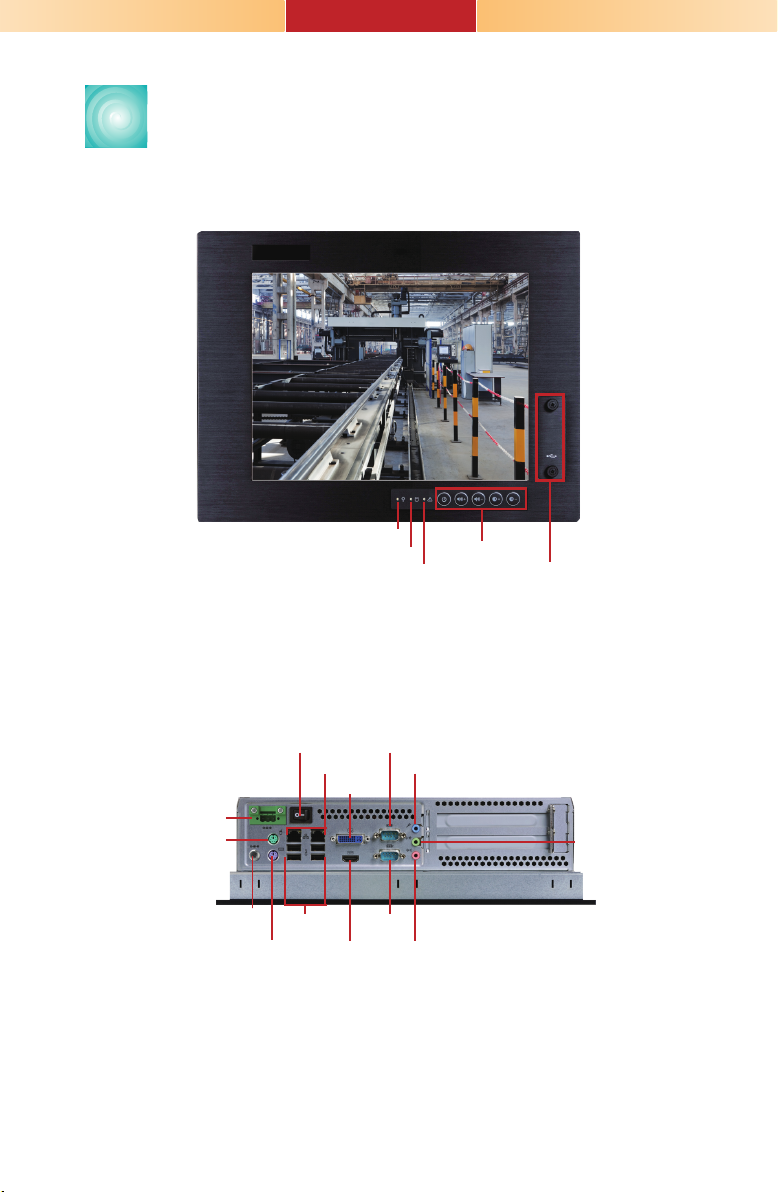
TPC121
Front View
Bottom View
+16-30V DC-in
PS/2 Mouse
+19V DC-in
(default)
Power Switch
USB 2.0
PS/2 KB
LAN
Power LED
DVI-I
HDMI
HDD LED
Alarm LED
COM 2
Line-in
COM 1
Mic-in
Function Keys
USB
Line-out
2
Page 3
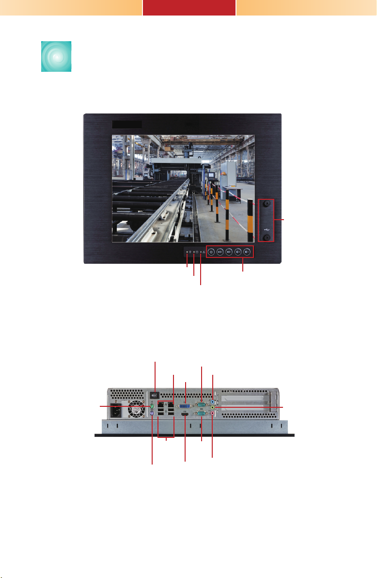
TPC150
Front View
USB
Bottom View
PS/2 Mouse
Power LED
Power Switch
LAN
USB 2.0
PS/2 KB
HDD LED
Alarm LED
DVI-I
COM 1
HDMI
Function Keys
COM 2
Line-in
Line-out
Mic-in
3
Page 4
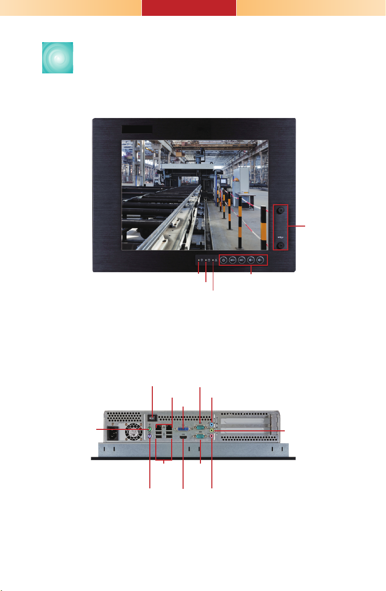
TPC170
Front View
USB
Bottom View
PS/2 Mouse
Power Switch
LAN
USB 2.0
PS/2 KB
Power LED
HDD LED
COM 2
DVI-I
COM 1
HDMI
Function Keys
Alarm LED
Line-in
Line-out
Mic-in
4
Page 5

Key Features
Processor
Chipset
LAN
COM
Dual Displays
USB
Audio
HDMI
TPC121/150/170
3rd/2nd Generation Intel® CoreTM processors
Intel® H61 Express Chipset
2 LAN ports
2 COM ports
HDMI and DVI-I
4 Type A USB 2.0/1.1 ports at the bottom
2 Type A USB 2.0/1.1 ports at the front panel
Mic-in, Line-in, Line-out
2 3W speakers
1 HDMI port
5
Page 6
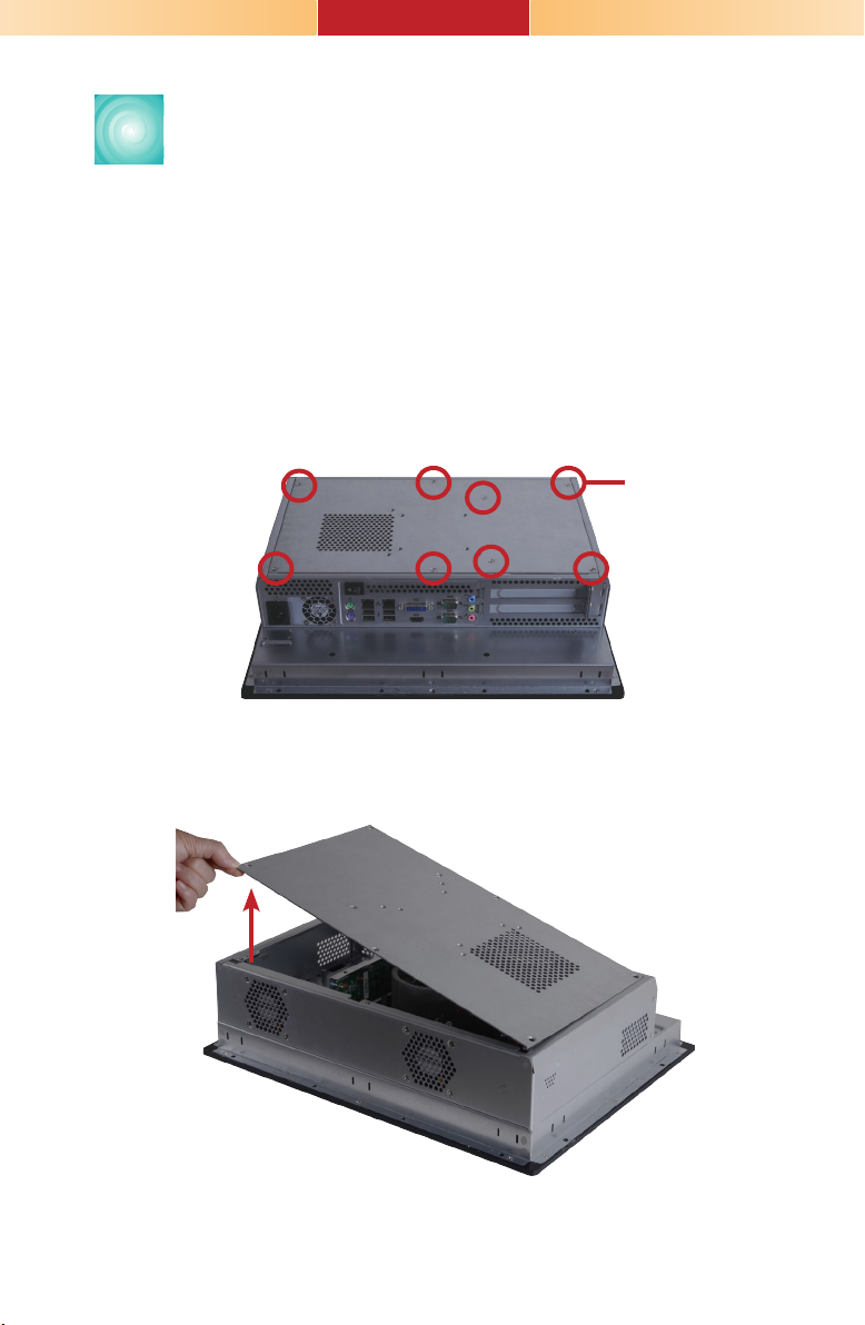
Removing the Chassis Cover
1. Make sure the system and all other peripheral devices
connected to it has been powered-off.
2. Disconnect all power cords and cables.
3. The 8 mounting screws on the rear side of the system
are used to secure the cover to the chassis. Remove
these screws and then put them in a safe place for
later use.
Mounting Screw
4. After removing the mounting screws, lift the cover up.
Lift the Cover Upward
6
Page 7
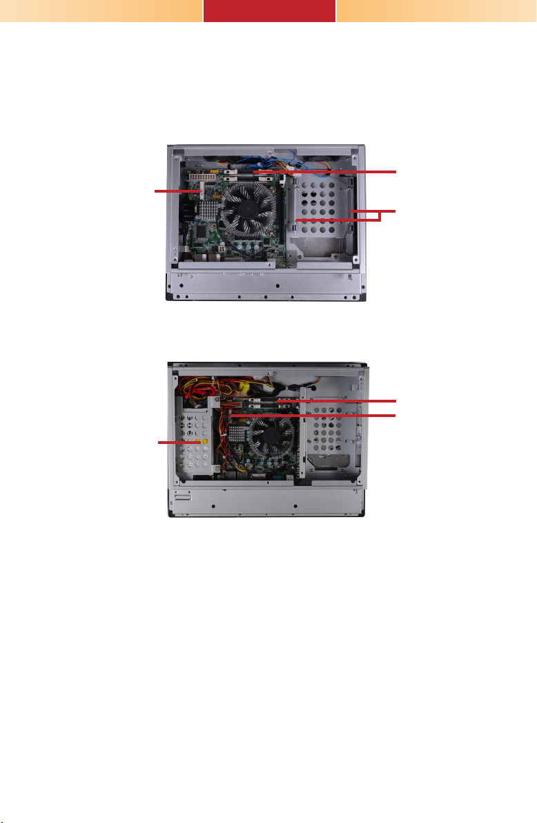
5. The memory socket, expansion slots, Mini PCIe slot
and SATA drive bay are readily accessible after
removing the chassis cover.
TPC121
SODIMM socket
Mini PCIe Slot
SATA drive bay
TPC150/ TPC170
SODIMM socket
Mini PCIe slot
SATA drive bay
7
Page 8
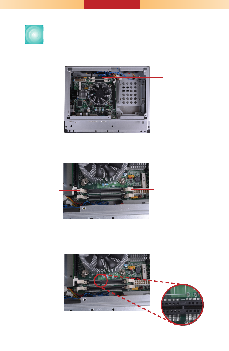
Installing an SODIMM
1. Locate the DIMM socket on the system board.
SODIMM socket
2. Push the ejector tabs which are at the ends of the
socket at the side.
Ejector tab
Ejector tab
3. Note the key on the socket. The key ensures the
module can be plugged into the socket in only one
direction.
8
Page 9
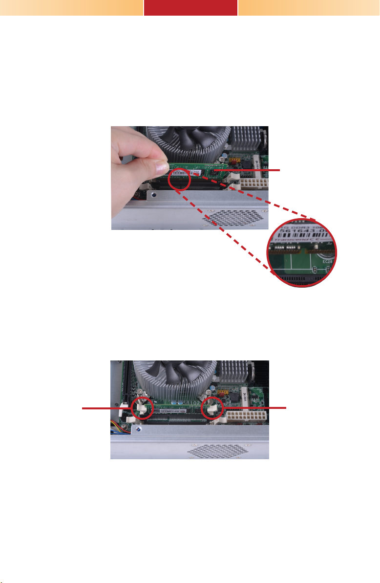
4. Grasping the module by its edges, position the module
above the socket with the notch in the socket aligned
with the key on the module. Apply rm even pressure
to each end of the module until it slips down into the
socket. The contact ngers on the edge of the module
will almost completely disappear inside the socket.
SODIMM
5. Push the module down until the clips at each end of
the socket lock into position. You will hear a distinctive
“click”, indicating the module is correctly locked into
position.
Clip Clip
9
Page 10

Installing a SATA Drive
1. Locate the SATA drive bay in the chassis.
TPC121
TPC150/ TPC170
SATA drive bay
SATA drive bay
10
Page 11

2. Remove the mounting screws that secure the HDD
bracket to the drive bay.
TPC121
Mounting Screw
TPC150/ TPC170
Mounting Screw
11
Page 12

3. Align the mounting holes of the SATA drive with the
mounting holes on the HDD bracket and then use the
provided mounting screws to secure the drive in place.
SATA drive
HDD bracket
Mounting screws
Mounting screw
4. Place the SATA drive (with HDD bracket) back into
place. Align the mounting holes on the HDD bracket
with the mounting holes on the SATA drive bay and
then use the provided mounting screws to secure the
drive in place.
HDD bracket
Mounting hole
12
Page 13

Mounting hole
Mounting screw
5. Connect one end to the SATA data connector on the
SATA drive and the other end to the SATA data
connector on the system board.
13
Page 14

SATA data connector
SATA power connector
SATA data connector
SATA power connector
SATA data
connector
14
Page 15

Installing a Mini PCIe Card
Latch
1. Locate the two Mini PCIe slots on the chassis.
Mini PCIe slot
Mini PCIe slot
15
Page 16

2. The latch is used to lock the Mini PCIe card into
position. Insert the latch into the mounting holes and
then push the latch down until the clips at each end of
the latch lock into position. You will hear a distinctive
"click", indicating the latch is correctly locked into
position.
Latch
Mounting hole
Mini PCIe slot
16
Latch
Page 17

3. The system board is equipped with a Mini PCIe slot.
The Mini PCIe slot supports half length Mini PCIe card.
Note the key on the slot. The key ensures the Mini
PCIe card can be plugged into the slot in only one
direction.
Removing the latch
If you want to move the latch in order to use the desired
card, please follow below steps:
1. Remove the clips at each end of the latch once at a
time.
2. Press the clips to the center of the latch and pull it up.
Pull up
Press to
the center
Latch
3. Pull the clips up and remove the latch.
17
Page 18

Installing the Mini PCIe Card
1. Grasping the Mini PCIe card by its edges, align the
card into the slot at an approximately 30 degrees angle.
Apply rm even pressure to each end of the card until it
slips down into the slot. The contact ngers on the edge
of the card will almost completely disappear inside the
slot.
2. Push the Mini PCIe card down until the clips at each
end of the latch lock into position. You will hear a
distinctive “click”, indicating the card is correctly locked
into position.
Clip
Clip
18
Page 19

Installing the PCI and PCIe x1
Expansion Card
1. The PCI and PCIe x1 slots on the riser card are used to
install the expansion cards. To install the expansion
cards, you need to remove the mounting screws that
secure the brackets to the chassis then remove the
brackets.
PCIe x1
Bracket
Mounting screw
2. Remove these mounting screws and brackets, and
then put them in a safe place for later use.
3. Insert the Expansion card with a bracket into the slot
that is on the riser card. Replace the screw you
removed in step 2 to secure the bracket in place.
Expansion card
PCI
Note:
The Expansion card used in the illustration above may not resemble the
actual card. These illustrations are for reference only.
19
Page 20

Connecting Cables to Terminal Blocks
1. Insert the cable end of the power adaptor to the
terminal block. To rmly x the cable into the terminal
block, use a screwdriver to clamp down the wires to
the screw that is in the terminal block.
Terminal block
Wire
Power adapter cable
20
Page 21

2. Plug the terminal block into the DC-in connector and
then tighten the screws to secure the terminal block in
place.
DC-in
connector
Screws
21
Page 22

Mounting Options
Wall mount
The wall mount kit includes the following:
• 2 Wall mount brackets
• Bracket screws
Wall mount bracket 1 Wall mount bracket 2
1. Select a place on the wall where you will mount the
Panel PC.
2. Use the provided mounting screws to attach “wall
mount bracket 1” to the wall.
22
Mounting screw
Wall mount bracket 1
Page 23

3. Attach the other bracket (wall mount bracket 2) to the
rear of the Panel PC.
Mounting screw
Wall mount bracket 2
Hooks
4. Using the hooks on “bracket 2”, slide the Panel PC to
“bracket 1”.
23
Wall mount bracket 2
Wall mount bracket 1
Page 24

5. Tighten the screw to hold the assembly in place.
Mounting screw
24
Page 25

241.00
321.00
Panel mount
296.00
386.00
339.00
420.00
The panel mounting kit includes the following:
• 10 mounting clamps (TPC121 and TPC150)
• 12 mounting clamps (TPC170)
1. Select a place on the panel where you will mount the
Panel PC.
2. Cut out a shape on the panel that corresponds to the
Panel PC’s rear dimensions.
TPC121
TPC150
3. Stick the poron foam on the rear panel.
Poron foam
25
TPC170
Poron foam
Page 26

4. Slide the Panel PC through the hole until it is properly
tted against the panel.
5. Position the mounting clamps along the rear edges of
the Panel PC, tting them into the slits that are around
the Panel PC.
Slit for mounting
the clamp
Mounting clamp
White plastic cap
6. The rst and second clamps must be positioned and
secured diagonally prior to mounting the rest of the
clamps. Tighten the clamp’s screw using an electric
screwdriver until the white plastic cap touches the
panel. Do not over tighten the screws to prevent
damaging the Panel PC. The illustration below shows
all clamps properly mounted.
26
Page 27

386.00
296.00
27
Page 28

Board Layout and Jumper Settings
USB 0-1/8-9 Power select
(JP4)
KB_MS
PS2 KS/MS Power Select(JP2)
USB 2.0 (0-1)
LAN 1
USB 2.0 (8-9)
LAN 2
DVI
HDMI
COM 1
COM 2
9
10
Line-in
Line-out
Mic-in
ALC886
8
DIO
1
1
1
2
1
Intel WG82574L
ATX 12V
ASmedia ASM1442
ASmedia ASM1442
COM1 signal select(JP3)
2
2
6
6
5
5
1
1
COM1 RS232/422/485
Select(JP1)
Front audio
1
2
1
Audio
1
Amplifier
1
2
CPU FAN
5
6
Front audio/
Audio Amplifier (JP5)
1
Chassis
intrusion
SDVO
1
Fintek
F71879F
DIO Power
1
30
29
SATA 0
1
Clear CMOS(JP9)
LGA 1155
PCIe x16
Intel
H61
SATA 1
Battery
SATA 4
SATA 5
SPI Flash
BIOS
USB 2-3
Standby power LED
Mini PCIe
Front Panel
1
USB 2-3/10-11
power select(JP7)
Power-on
Select (JP8)
1
20
1
System_Fan2
ATX power
11011
DDR3_1 SODIMM
Buzzer
10
1
1
2
DDR3_2 SODIMM
System_Fan1
USB 10-11
2
1
11
RS232/RS422/RS485 Select: COM 1 (JP1)
RS232 (default) 1-2 On
RS422 Full Duplex 3-4 On
RS485 5-6 On
Clear CMOS JP9
Normal (default) 1-2 On
Clear CMOS 2-3 On
USB Power: 0-1/8-9 (JP4), 2-3/10-11 (JP7)
+5V (default) 1-2 On
+5V_standby 2-3 On
COM 1 Signal Select JP3
Pin-9 is RI (default) 1-3 On
Pin-9 is VCC(+5V) 3-5 On
Pin-1 is DCD (default) 2-4 On
Pin-1 is VCC12(+12V) 4-6 On
PS/2 Power JP2
+5V (default) 1-2 On
+5V_standby 2-3 On
Front Audio or Audio Amplier JP5
Front Audio (default) 1-3 On
Audio Amplier 3-5 On
Power-on Select JP8
Power-on via power button (default) 1-2 On
Power-on via AC Power
Power-on via WOL After G3
934-TPC121-000G
28
2-4 On
4-6 On
2-3 On
A24601243
 Loading...