

DFI SU256-SCM User Manual
SU256-SCM
Embedded SBC 4”
User’s Manual
A50900932
1
Preliminary
Version

Copyright
FCC and DOC Statement on Class B
This publication contains information that is protected by copyright. No part of it may be reproduced in any form or by any means or used to make any transformation/adaptation without
the prior written permission from the copyright holders.
This publication is provided for informational purposes only. The manufacturer makes no
representations or warranties with respect to the contents or use of this manual and specifically disclaims any express or implied warranties of merchantability or fitness for any particular
purpose. The user will assume the entire risk of the use or the results of the use of this document. Further, the manufacturer reserves the right to revise this publication and make changes
to its contents at any time, without obligation to notify any person or entity of such revisions
or changes.
Changes after the publication’s first release will be based on the product’s revision. The website
will always provide the most updated information.
© 2019. All Rights Reserved.
Trademarks
Product names or trademarks appearing in this manual are for identification purpose only and
are the properties of the respective owners.
This equipment has been tested and found to comply with the limits for a Class B digital
device, pursuant to Part 15 of the FCC rules. These limits are designed to provide reasonable protection against harmful interference when the equipment is operated in a residential
installation. This equipment generates, uses and can radiate radio frequency energy and, if not
installed and used in accordance with the instruction manual, may cause harmful interference
to radio communications. However, there is no guarantee that interference will not occur in a
particular installation. If this equipment does cause harmful interference to radio or television
reception, which can be determined by turning the equipment off and on, the user is encouraged to try to correct the interference by one or more of the following measures:
• Reorient or relocate the receiving antenna.
• Increase the separation between the equipment and the receiver.
• Connect the equipment into an outlet on a circuit different from that to which the receiver
is connected.
• Consult the dealer or an experienced radio TV technician for help.
Notice:
1. The changes or modifications not expressly approved by the party responsible for compliance could void the user’s authority to operate the equipment.
2. Shielded interface cables must be used in order to comply with the emission limits.
2

Table of Contents
Copyright .............................................................................................................2
Trademarks ........................................................................................................ 2
FCC and DOC Statement on Class B .....................................................2
Warranty ..............................................................................................................4
Static Electricity Precautions ......................................................................4
Safety Measures ..............................................................................................4
Before Using the System Board ...............................................................5
Chapter 1 - Introduction .............................................................................6
Specifications ................................................................................................6
Features ..........................................................................................................7
Chapter 2 - Hardware Installation ������������������������������������������������ 8
Board Layout .................................................................................................8
Block Diagram ...............................................................................................9
Mechanical Diagram ....................................................................................9
System Memory .......................................................................................... 10
Jumper Settings ......................................................................................... 10
Clear CMOS ................................................................................................ 10
Auto Power-on Select ..................................................................................11
Mini PCIe Signal Select ............................................................................... 11
Front Panel I/O Ports ................................................................................12
Rear Panel I/O Ports .................................................................................12
15~36V DC-in ............................................................................................ 13
Graphics Interface ......................................................................................13
USB Ports ................................................................................................... 14
RJ45 LAN Ports ........................................................................................... 15
I/O Connectors ........................................................................................... 16
Serial ATA Connector .................................................................................. 16
Serial ATA Power Connector ........................................................................ 16
Expansion Slot ............................................................................................ 16
Cooling Fan Connector ................................................................................ 17
SMBus Connector ....................................................................................... 17
Front Panel Connector ................................................................................ 18
Battery ....................................................................................................... 19
Overview....................................................................................................... 20
Insyde BIOS Setup Utility ........................................................................ 21
Main .......................................................................................................... 21
Advanced ................................................................................................... 21
Security ...................................................................................................... 29
Boot........................................................................................................... 30
Exit ............................................................................................................ 31
Updating the BIOS .................................................................................... 31
Notice: BIOS SPI ROM ............................................................................. 32
Chapter 4 - Supported Software ........................................................... 33
Chapter 5 - RAID .......................................................................................... 48
Chapter 6 - Intel AMT Settings .............................................................. 51
Overview ................................................................................51
Enable Intel® AMT in the Insyde BIOS .....................................51
Configure Intel® AMT in the Intel® Management Engine BIOS
Extension (MEBX) Section .......................................................52
Chapter 3 - BIOS Setup ��������������������������������������������������������������� 20
3

Warranty
Static Electricity Precautions
1. Warranty does not cover damages or failures that arised from misuse of the product, inability to use the product, unauthorized replacement or alteration of components and product specifications.
2. The warranty is void if the product has been subjected to physical abuse, improper installation, modification, accidents or unauthorized repair of the product.
3. Unless otherwise instructed in this user’s manual, the user may not, under any circumstances, attempt to perform service, adjustments or repairs on the product, whether in or
out of warranty. It must be returned to the purchase point, factory or authorized service
agency for all such work.
4. We will not be liable for any indirect, special, incidental or consequencial damages to the
product that has been modified or altered.
It is quite easy to inadvertently damage your PC, system board, components or devices even
before installing them in your system unit. Static electrical discharge can damage computer
components without causing any signs of physical damage. You must take extra care in handling them to ensure against electrostatic build-up.
1. To prevent electrostatic build-up, leave the system board in its anti-static bag until you are
ready to install it.
2. Wear an antistatic wrist strap.
3. Do all preparation work on a static-free surface.
4. Hold the device only by its edges. Be careful not to touch any of the components, contacts
or connections.
5. Avoid touching the pins or contacts on all modules and connectors. Hold modules or connectors by their ends.
Important:
Electrostatic discharge (ESD) can damage your processor, disk drive and other components. Perform the upgrade instruction procedures described at an ESD workstation only. If such a station is not available, you can provide some ESD protection by
wearing an antistatic wrist strap and attaching it to a metal part of the system chassis. If a wrist strap is unavailable, establish and maintain contact with the system
chassis throughout any procedures requiring ESD protection.
Safety Measures
To avoid damage to the system:
• Use the correct AC input voltage range.
To reduce the risk of electric shock:
• Unplug the power cord before removing the system chassis cover for installation or servicing. After installation or servicing, cover the system chassis before plugging the power
cord.
4

Before Using the System Board
Before using the system board, prepare basic system components.
If you are installing the system board in a new system, you will need at least the following
internal components.
• Storage devices such as hard disk drive, etc.
You will also need external system peripherals you intend to use which will normally include at
least a keyboard, a mouse and a video display monitor.
5

Chapter 1 - Introduction
Specifications
Chapter 1
SYSTEM Processor 6th Generation Intel® Core™ Processors, BGA 1356 (Skylake-U*)
Memory DDR4-2400 SO-DIMM 260pin 8GB (1R*8) x 2pcs
GRAPHICS Controller Intel® HD Graphics GT Series
EXPANSION Interface 1 x Full-size Mini PCIe
ETHERNET Controller 3 x Intel® I210IT PCIe (10/100/1000Mbps)
REAR I/O Ethernet
FRONT I/O USB
INTERNAL I/O
WATCHDOG
TIMER
SECURITY TPM TPM 2.0
POWER Type Wide Range 15~36V
BIOS Insyde SPI 128Mbit
Feature OpenGL 5.0, DirectX 12, OpenCL 2.1
Display 1 x HDMI
Storage 1 x Flash Module mSATA SATAIII 256GB MLC
USB
Display 1 x HDMI
SATA 1 x SATA 3.0 (up to 6Gb/s)
SMBus 1 x SMBus
Output &
Interval
Connector Terminal Block
Consumption TBD
RTC Battery CR2032 Coin Cell
Intel® Core™ i7-6600U Processor, Dual Core, 4M Cache, 2.6GHz (3.4GHz), 15W
Intel® Core™ i5-6300U Processor, Dual Core, 3M Cache, 2.4GHz (3.0GHz), 15W
Intel® Core™ i3-6100U Processor, Dual Core, 3M Cache, 2.3GHz, 15W
Intel® Core™ i7-7600U Processor, Dual Core, 4M Cache, 2.8GHz (3.9GHz), 15W
HW Decode: AVC/H.264, MPEG2, VC1/WMV9, JPEG/MJPEG, HEVC/H265, VP8, VP9
HW Encode: AVC/H.264, MPEG2, JPEG, HEVC/H265, VP8, VP9
1 x Intel® I219LM PCIe with iAMT9.5 (10/100/1000Mbps) (only Core i7/i5 supports iAMT)
4 x GbE (RJ-45)
4 x USB 3.0
2 x USB 3.0
1 x SATA Power
System Reset, Programmable via Software from 1 to 255 Seconds
OS SUPPORT Microsoft/
ENVIRONMENT Temperature Operating: -20 to 70°C
MECHANICAL Dimensions 4" SBC Form Factor
Linux
Humidity TBD
MTBF TBD
Height PCB: 1.6mm
Windows 7 (32/64-bit)
Windows 8.1 (64-bit)
Windows 10
WES 7
WE8S
CentOS 7 (1804)
Storage: -40 to 85°C
165mm (6.49") x 135mm (5.31")
Top Side: TBD, Bottom Side: TBD
6
Chapter 1 Introduction www.d.com

Chapter 1
Features
• Watchdog Timer
The Watchdog Timer function allows your application to regularly “clear” the system at the set
time interval. If the system hangs or fails to function, it will reset at the set time interval so
that your system will continue to operate.
• DDR4
DDR4 deliver increased system bandwidth and improved performance at a lower power than
DDR3 and DDR3L. It is not compatible with older standards of DDR memories.
• Graphics
The integrated Intel® HD graphics engine delivers an excellent blend of graphics performance
and features to meet business needs. It provides excellent video and 3D graphics with outstanding graphics responsiveness. These enhancements deliver the performance and compatibility needed for today’s and tomorrow’s business applications. Supports 1 HDMI interface for
display output.
• Serial ATA
Serial ATA is a storage interface that is compliant with SATA 1.0a specification. With speed of
up to 6Gb/s (SATA 3.0), it improves hard drive performance faster than the standard parallel
ATA whose data transfer rate is 100MB/s.
• Gigabit LAN
Four Intel® Gigabit LAN controllers (three Intel® I210IT PCI Express Gigabit Ethernet controllers and one Intel® I219LM Gigabit Ethernet Phy) support up to 1Gbps data transmission.
• Wake-On-LAN
This feature allows the network to remotely wake up a Soft Power Down (Soft-Off) PC. It is
supported via the onboard LAN port or via a PCI LAN card that uses the PCI PME (Power Management Event) signal. However, if your system is in the Suspend mode, you can power-on
the system only through an IRQ or DMA interrupt.
• Wake-On-USB
This function allows you to use a USB keyboard or USB mouse to wake up a system from the
S3 (STR - Suspend To RAM) state.
• ACPI STR
The system board is designed to meet the ACPI (Advanced Configuration and Power Interface)
specification. ACPI has energy saving features that enables PCs to implement Power Management and Plug-and-Play with operating systems that support OS Direct Power Management.
ACPI when enabled in the Power Management Setup will allow you to use the Suspend to RAM
function�
With the Suspend to RAM function enabled, you can power-off the system at once by pressing
the power button or selecting “Standby” when you shut down Windows® without having to go
through the sometimes tiresome process of closing files, applications and operating system.
This is because the system is capable of storing all programs and data files during the entire
operating session into RAM (Random Access Memory) when it powers-off. The operating session will resume exactly where you left off the next time you power-on the system.
• Power Failure Recovery
When power returns after an AC power failure, you may choose to either power-on the system
manually or let the system power-on automatically.
• USB
The system board supports the USB 3.0. It is capable of running at a maximum transmission
speed of up to 5 Gbit/s (625 MB/s) and is faster than USB 2.0 (480 Mbit/s, or 60 MB/s) and
USB 1.1 (12Mb/s). USB 3.0 reduces the time required for data transmission, reduces power
consumption, and is backward compatible with USB 2.0. It is a marked improvement in device
transfer speeds between your computer and a wide range of simultaneously accessible external Plug and Play peripherals.
Chapter 1 Introduction
7
www.d.com

Chapter 2 - Hardware Installation
Board Layout
Chapter 2
SATA Power
4
1
SATA 3.0
SATA 0
1
1
3
Mini PCIe Signal Select (JP3)
HDMI
Mini PCIe
TPM 2.0
Clear CMOS (JP4)
3
1
1
Battery
USB 2-3
USB 3.0
SPI Flash BIOS
Buzzer
1
2
6
5
Front Panel
USB 0-1
USB 3.0
LAN 4
Intel I210IT
DDR4_2 SODIMM
DDR4_1 SODIMM
LAN 3
Intel I210IT
LAN 2
Intel I210IT
2
1
SMBus
LAN 1
5
DC-IN
21
Auto Power-on Select (JP7)
USB 3.0
USB 4-5
3
CPU Fan
1
1
Intel I219LM
Intel
Core i7/i5/i3
Nuvoton NCT6102D
Chapter 2 Hardware Installation
Top View
Bottom View
8
www.dfi .com
Chapter 2
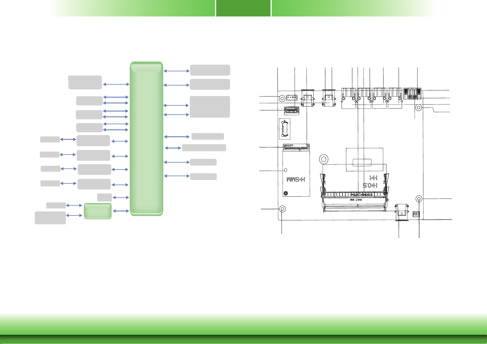
Block Diagram
GLAN I219LM
Terminal Block
LAN
LAN
LAN
LAN
Power/Reset
Buttom
MDI
MDI
MDI
MDI
FAN
2 Pin
USB 3.0 2x
USB 3.0 2x
USB 3.0 2x
GLAN I219LM
GLAN I219LM
GLAN I210IT
GLAN I210IT
GLAN I210IT
HDMI
Super IO
with WDT
power input
USB 3.0
USB 2.0
USB 3.0
USB 2.0
USB 3.0
USB 2.0
PCIe x1
PCIe x1
PCIe x1
PCIe x1
DDI
LPC
Core
i7/i5/i3
Channel A
Channel B
PCIe/
SATA (default)
USB 2.0
SATA 3.0
LPC
SMBus
4GB/8GB DDR4
SODIMM
4GB/8GB DDR4
SODIMM
Full-size
Mini PCIe
SATA 3.0
TPM 2.0
SPI
SMBus
Mechanical Diagram
145.52
165.00
131.66
8.00
10.44
19.51
58.75
156.28
123.20
160.00
127.39
103.33
79.91
81.95
67.72
62.41
44.91
124.56
27.41
27.99
7.28
9.50
5.00
0.00
7.35
14.59
18.00
113.20
135.00
Chapter 2 Hardware Installation
9
www.dfi .com
Chapter 2
Important:
Electrostatic discharge (ESD) can damage your board, processor, disk drives, add-in
boards, and other components. Perform installation procedures at an ESD workstation
only. If such a station is not available, you can provide some ESD protection by wearing an antistatic wrist strap and attaching it to a metal part of the system chassis. If
a wrist strap is unavailable, establish and maintain contact with the system chassis
throughout any procedures requiring ESD protection.
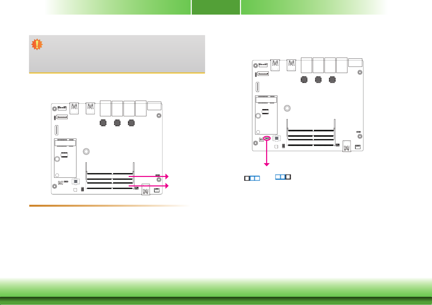
System Memory
Jumper Settings
Clear CMOS
JP4
2
DDR4_2 SODIMM
DDR4_1 SODIMM
13
2
1-2 On:
Normal (default)
13
2-3 On:
Clear CMOS
Features
• Two 260-pin SODIMM up to 8GB
• Dual Channel DDR4 2400MHz
Chapter 2 Hardware Installation
If you encounter the following,
a) CMOS data becomes corrupted.
b) You forgot the supervisor or user password.
you can reconfigure the system with the default values stored in the ROM BIOS.
To load the default values stored in the ROM BIOS, please follow the steps below.
1. Power-off the system and unplug the power cord.
2. Set JP4 pins 2 and 3 to On. Wait for a few seconds and set JP4 back to its default setting,
pins 1 and 2 On.
3. Now plug the power cord and power-on the system.
10
www.dfi .com
Chapter 2
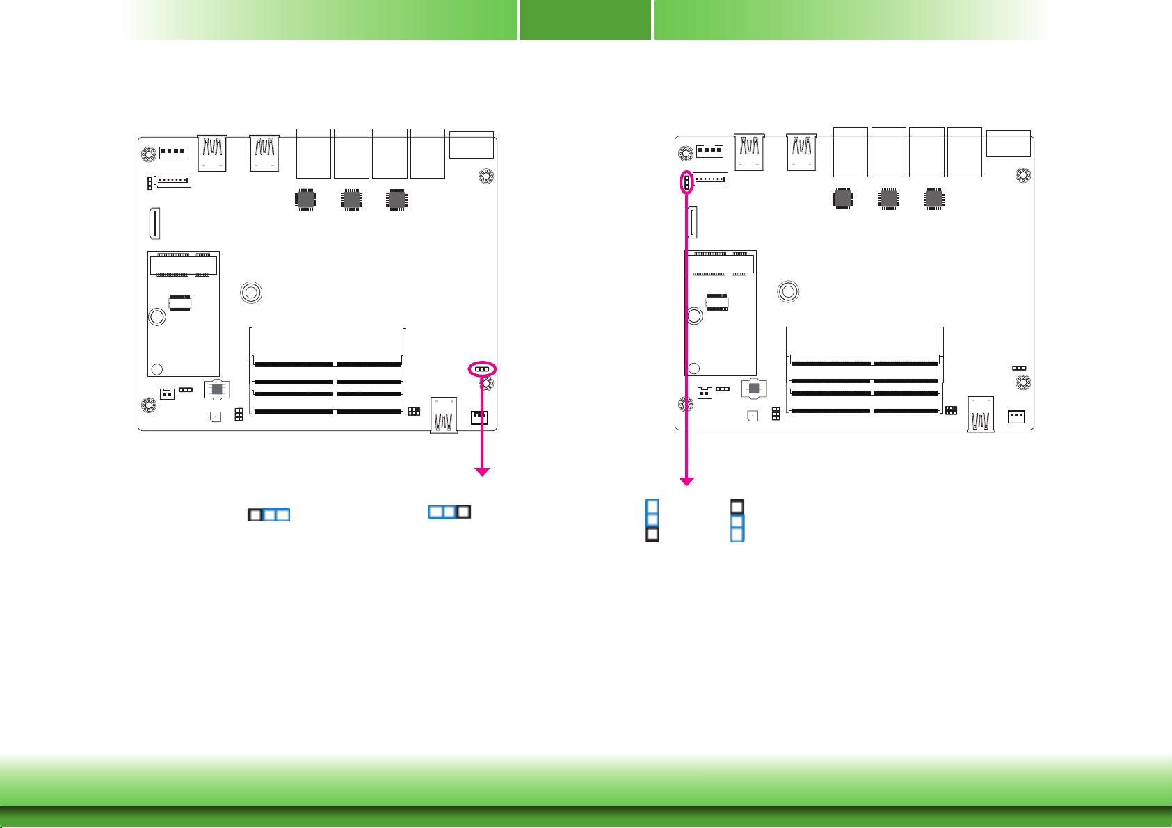
Auto Power-on Select
JP7
13
2
1-2 On:
Power-on via power button
(default)
JP7 is used to select the method of powering on the system. If you want the system to power-on whenever AC power comes in, set JP7 pins 2 and 3 to On. If you want to use the power
button, set pins 1 and 2 to On.
2
13
2-3 On:
Power-on via AC power
Mini PCIe Signal Select
JP3
1
2
3
1-2 On:
mSATA (default)
JP3 is used to select the Mini PCIe signal: PCIe or mSATA (default).
1
2
3
2-3 On:
PCIe
When using the JP7 “Power On” feature to power the system back on after a power failure
occurs, the system may not power on if the power lost is resumed within 5 seconds (power
flicker).
Chapter 2 Hardware Installation
11
www.dfi .com
Chapter 2
DC-in
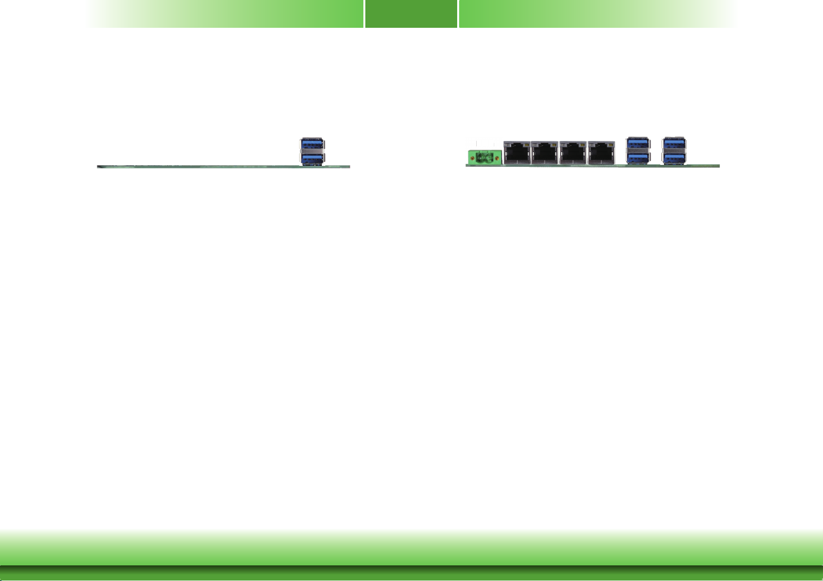
Front Panel I/O Ports
The front panel I/O ports consist of the following:
• 2 USB 3.0 ports
USB 3.0
Rear Panel I/O Ports
LAN 2
LAN 1
DC-in
The rear panel I/O ports consist of the following:
• 1 15~36V DC-in 2-pin terminal block
• 4 LAN ports
• 4 USB 3.0 ports
LAN 3
LAN 4
USB 3.0
USB 3.0
Chapter 2 Hardware Installation
12
www.dfi .com

Chapter 2
15~36V DC-in
1
2
WIDE_DC Ground
DC-in
Graphics Interface
The display port consists of the following:
• 1 HDMI port
HDMI
HDMI Port
The HDMI port which carries both digital audio and video signals is used to connect a LCD
monitor or digital TV that has the HDMI port.
Connect a DC power cord to the 2-pin terminal block. Using a voltage more than the recommended range may fail to boot the system or cause damage to the system board.
Chapter 2 Hardware Installation
13
www.dfi .com
Chapter 2
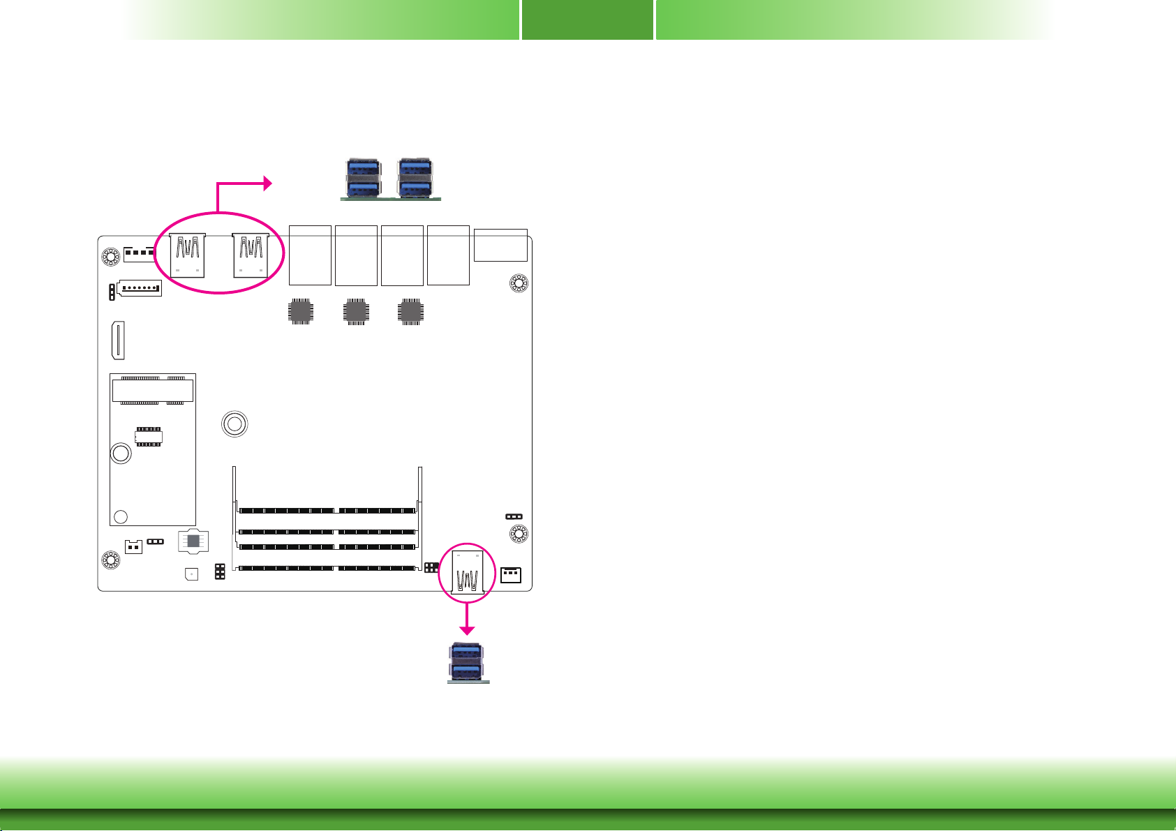
USB Ports
USB 1
USB 0
USB 3.0
USB 3
USB 2
The USB device allows data exchange between your computer and a wide range of simultaneously accessible external Plug and Play peripherals.
The system board is equipped with 6 onboard USB 3.0 port (USB 0-1/2-3/4-5).
BIOS Setting
Configure the onboard USB in the Advanced menu (“USB Configuration” submenu) of the
BIOS. Refer to chapter 3 for more information.
Driver Installation
You may need to install the proper drivers in your operating system to use the USB device.
Refer to chapter 4 for more information.
Wake-On-USB Keyboard/Mouse
The Wake-On-USB Keyboard/Mouse function allows you to use a USB keyboard or USB mouse
to wake up a system from the S3 (STR - Suspend To RAM) state.
Chapter 2 Hardware Installation
USB 5
USB 4
USB 3.0
14
www.dfi .com

Chapter 2
LAN 3
RJ45 LAN Ports
LAN 2LAN 1
LAN 4LAN 3
Features
• 3 Intel
• 1
The LAN ports allow the system board to connect to a local area network by means of a network hub.
Driver Installation
Install the LAN drivers. Refer to chapter 4 for more information.
®
I210IT PCI Express Gigabit Ethernet controllers
Intel® I219LM PCI Express Gigabit Ethernet controller
Chapter 2 Hardware Installation
15
www.dfi .com
Chapter 2
I/O Connectors
Serial ATA Connector
Serial ATA Power Connector
SATA Power
GND
TX-
TX+
GND
+5V
GND
RX-
4
GND
RX+
7
1
+12V
GND
1
SATA 0
SATA 3.0 6Gb/s
Expansion Slot
Full-size Mini PCIe (PCIe and mSATA signals)
Features
• 1 Serial ATA 3.0 port with data transfer rate up to 6Gb/s
• Integrated Advanced Host Controller Interface (AHCI) controller
The Serial ATA connector is used to connect the Serial ATA device. Connect one end of the Serial ATA data cable to a SATA connector and the other end to your Serial ATA device.
The SATA power connector supplies power to the SATA drive. Connect one end of the provided
power cable to the SATA power connector and the other end to your storage device.
BIOS Setting
Configure the Serial ATA drives in the Advanced menu (“SATA Configuration” submenu) of the
BIOS. Refer to chapter 3 for more information.
Chapter 2 Hardware Installation
Mini PCI Express Slot
The full-size Mini PCIe socket supports the installation of a Mini PCIe card or an mSATA card
(flash module mSATA SATAIII 256GB MLC) .
To switch between these two signals, use JP3. Refer to the previous section for more information.
16
www.dfi .com
Chapter 2
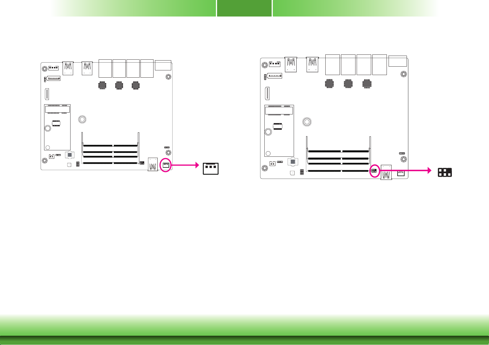
Cooling Fan Connector
CPU Fan
3
PWR
Sense
1
GND
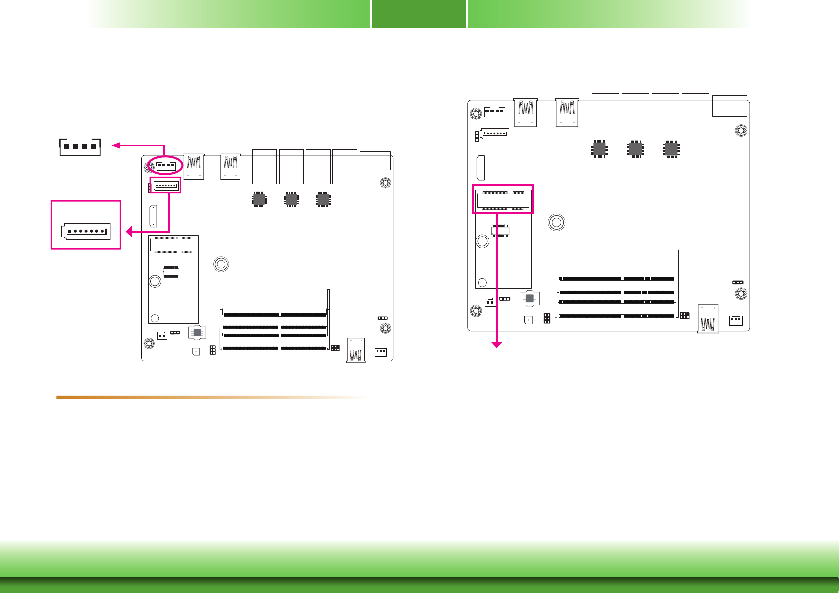
SMBus Connector
SMBus
GND
2
1
3V3SB
SMB_DATA
5
SMB_CLK
SMB_ALERT
The fan connector is used to connect the cooling fan. The cooling fan will provide adequate
airflow throughout the chassis to prevent overheating the CPU and system board components.
BIOS Setting
The Advanced menu (“SIO NUVOTON6102D” submenu) of the BIOS will display the current
speed of the cooling fans. Refer to chapter 3 for more information.
Chapter 2 Hardware Installation
The SMBus (System Management Bus) connector is used to connect SMBus devices. It is a
multiple device bus that allows multiple chips to connect to the same bus and enable each one
to act as a master by initiating data transfer.
17
www.dfi .com
Chapter 2
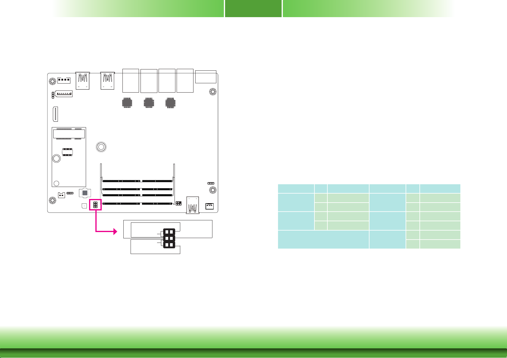
Front Panel Connector
Front
Panel
PWR-BTN
RESET-SW
1
2
56
Power-LED
SUS-LED
HDD-LED
HDD-LED - HDD LED
This LED will be lit when the hard drive is being accessed.
RESET-SW - Reset Switch
This switch allows you to reboot without having to power off the system.
PWR-BTN - Power Switch
This switch is used to power on or off the system.
PWR-LED - Power LED
When the system’s power is on, this LED will be lit.
SUS-LED - Suspend Mode LED
When the system is in the S1 (POS - Power On Suspend) state, it will blink every second.
When the system is in the S3 (STR - Suspend To RAM) state, it will blink every 4 seconds.
Pin Pin Assignment Pin Pin Assignment
HDD-LED
RESET-SW
3 GND
6
HD LED
3 GND
5 Signal 3
PWR-BTN
PWR-LED
SUS-LED
1 Power Button
3 GND
2 Power LED
GND
3
GND
4
SUS LED
Chapter 2 Hardware Installation
18
www.dfi .com
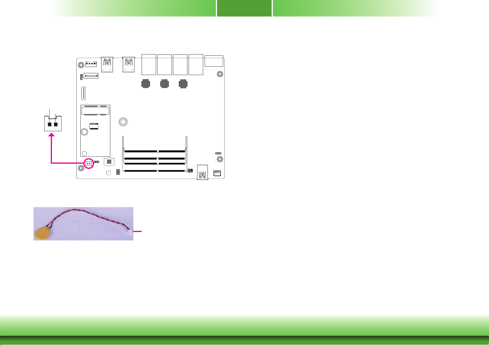
Battery
Battery
1
Chapter 2
GND
Battery
Connector
Battery
The lithium ion battery powers the real-time clock and CMOS memory. It is an auxiliary source
of power when the main power is shut off.
Safety Measures
• Danger of explosion if battery incorrectly replaced.
• Replace only with the same or equivalent type recommended by the manufacturer.
• Dispose of used batteries according to local ordinance
Connect to the battery connector
.
Chapter 2 Hardware Installation
19
www.dfi .com
Chapter 3
Chapter 3 - BIOS Setup
Overview
The BIOS is a program that takes care of the basic level of communication between the CPU
and peripherals. It contains codes for various advanced features found in this system board.
The BIOS allows you to configure the system and save the configuration in a battery-backed
CMOS so that the data retains even when the power is off. In general, the information stored
in the CMOS RAM of the EEPROM will stay unchanged unless a configuration change has been
made such as a hard drive replaced or a device added.
It is possible that the CMOS battery will fail causing CMOS data loss. If this happens, you need
to install a new CMOS battery and reconfigure the BIOS settings.
Note:
The BIOS is constantly updated to improve the performance of the system board;
therefore the BIOS screens in this chapter may not appear the same as the actual
one. These screens are for reference purpose only.
Default Configuration
Most of the configuration settings are either predefined according to the Load Optimal Defaults
settings which are stored in the BIOS or are automatically detected and configured without
requiring any actions. There are a few settings that you may need to change depending on
your system configuration.
Entering the BIOS Setup Utility
The BIOS Setup Utility can only be operated from the keyboard and all commands are keyboard commands. The commands are available at the right side of each setup screen.
The BIOS Setup Utility does not require an operating system to run. After you power up the
system, the BIOS message appears on the screen and the memory count begins. After the
memory test, the message “Press DEL to run setup” will appear on the screen. If the message
disappears before you respond, restart the system or press the “Reset” button. You may also
restart the system by pressing the <Ctrl> <Alt> and <Del> keys simultaneously.
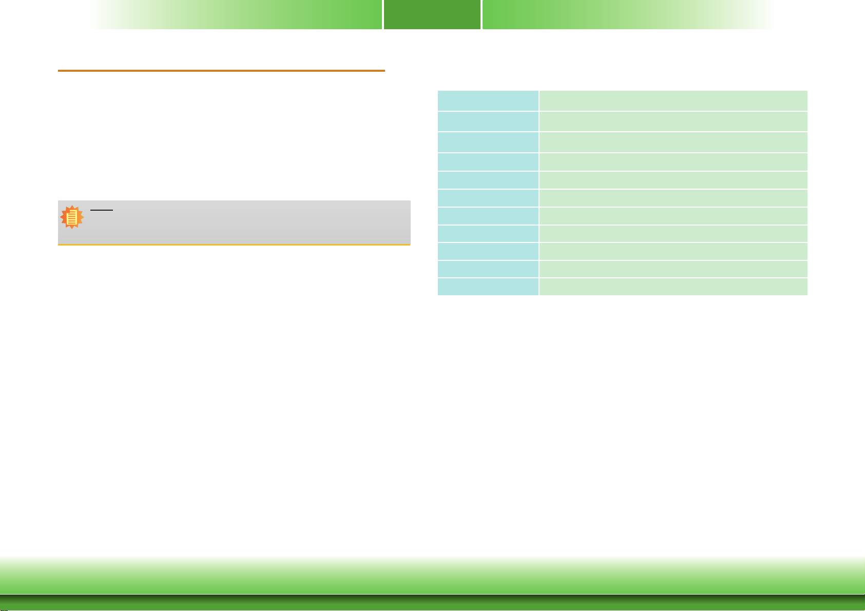
Legends
Keys Function
Right and Left arrows
Up and Down arrows
<Esc>
<F5>
<F6>
Tab
<F1>
<F9>
<F10>
<Enter>
Scrolls forward through the values or options of the highlighted eld.
Scrolls backward through the values or options of the highlighted eld.
Moves the highlight left or right to select a menu.
Moves the hightlight up or down between submenu or elds.
Exit to the BIOS Setup Utility.
Select a eld.
Displays general help
Optimized defaults
Saves and resets the setup program.
Press <Enter> to enter the highlighted submenu.
Scroll Bar
When a scroll bar appears to the right of the setup screen, it indicates that there are more
available fields not shown on the screen. Use the up and down arrow keys to scroll through all
the available fields.
Submenu
When “” appears on the left of a particular field, it indicates that a submenu which contains
additional options are available for that field. To display the submenu, move the highlight to
that field and press <Enter>.
20
20
Chapter 3 BIOS Setup
Chapter 3 BIOS Setup www.d.com
www.d.com
 Loading...