

Page 1
ST101-CP
Installation Guide
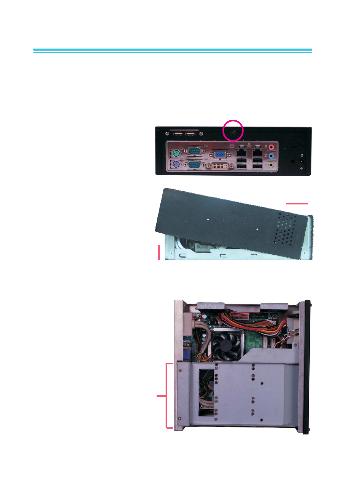
Removing the Chassis Cover
1. Make sure the system and all other peripheral devices connected to it has been
powered-off.
2. Disconnect all power cords and cables.
3. The screw at the rear panel is
used to secure the cover to the
chassis. Remove the cover screw
then put it in a safe place for later
use.
4 Lift the cover by first pulling it
backward (1) then lifting it up (2).
(2)
Removing the Drive Bay Bracket
1. The drive bay bracket is readily
accessible when you remove the
cover.
X
Side view
X
(1)
Drive bay
bracket
1/9
Page 2
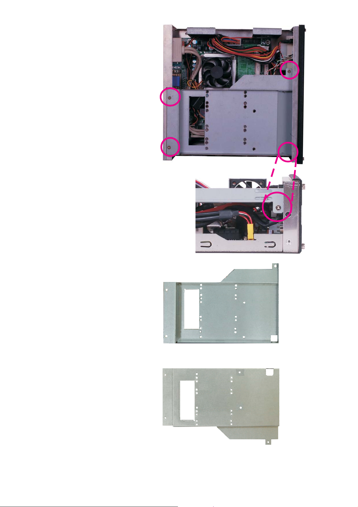
2. The 4 screws are used to secure
the drive bay bracket. Remove
these screws and put them in a
safe place for later use.
Top view
Side view
3. The drive bay bracket will
resemble the one shown on the
right.
Top of drive bay bracket
(for optical drive)
Bottom of drive bay bracket
(for SATA drive)
2/9
Page 3
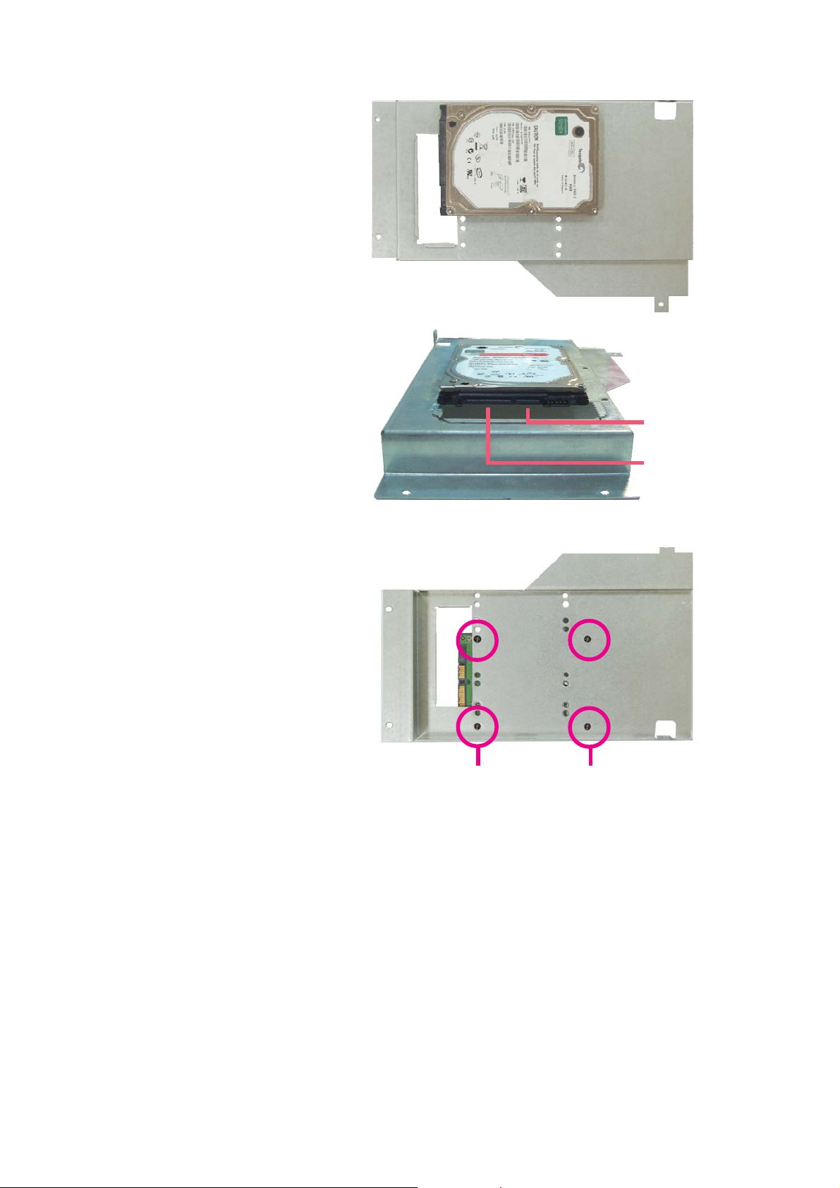
Installing the SATA and Optical Drives
1. Position the SATA drive at the
bottom side of the drive bay
bracket.
SATA data
connector
SATA power
connector
2. To secure SATA to the drive bay
bracket, you must fasten screws
from the top side of the drive
bay bracket.
While holding the SATA drive in
place, turn the drive bay bracket
to the top side then adjust the
drive so that the mounting holes
on the drive match the mounting
holes on the bracket. Now secure
the drive by fastening 4 screws.
Rear view of the SATA drive
Screw
Screw
3/9
Page 4

3. The 2 screws are used to secure
the drive bay cover. Remove these
screws and the drive bay cover.
Put them in a safe place for later
use.
4. After removing the drive bay
cover, on the top side of the
bracket, position the optical drive
as shown on the right.
Drive bay cover
5. Secure the optical drive by
fastening screws on each side of
the drive bay bracket.
Rear view of the optical drive
SATA
Optical drive
SATA
SATA
connector
Optical drive
4/9
Page 5

6. The figure on the right shows the
cables for SATA drive, the power
connector of the power supply
unit, and the locations of the SATA
connectors on the system board.
Power
connector
SATA
connector
7. Connect "A" to the power
connector of the power supply
unit.
Connect "B" to one of the SATA
connectors on the system board.
SATA data cable
For SATA drive
SATA power cable
C
A
B
Cable for DVD-ROM
(option)
5/9
Page 6

8. Connect the SATA data cable
and SATA power cable (from the
system board) to their respective
connectors at the rear of the
SATA drive.
SATA data cable
SATA power cable
9. Turn the drive bay bracket to the
top side. Insert the other end of
the cable for DVD-ROM (C)
through the bracket’s hole, up
to the top side of the bracket.
10. Connect the other end of the
cable for DVD-ROM (C) to
the SATA connector at the rear
of the optical drive.
Cable for DVD-ROM
6/9
Cable for DVD-ROM
Page 7

11. Insert the drive bay bracket
from the side of the system.
12. Secure the drive bay bracket by
fastening the screws you
removed earlier.
13. Replace the chassis cover and
secure it with the screw you
removed earlier.
14. Insert the provided power cord
holder. This will prevent the cord
from falling off easily or detaching from the system.
Insert holder here
Power cord
holder
15. When you power up the system, configure the drives in the BIOS. Refer to the
system board manual in the provided DVD.
16. Refer to the manual or documentation enclosed with the drives for additional
information on using the drive.
7/9
Page 8

Mounting ST101-CP (optional)
To mount the system on the wall, you need to prepare two mounting rails and
mounting screws.
1. If rubber feet has been
previously attached at the
bottom of the system, please
remove them first.
2. The mounting holes are located
at the bottom of the system.
Mount the mounting rails on each
side of the system using the
mounting screws you have
purchased.
3. Mount the whole system on the
wall by fastening screws through
the rail's mounting holes.
Note:
The pictures in this document are for illustration only. The system board and all
other components may differ depending on the configuration you have purchased.
Please refer to the provided DVD for details relevant to the system board.
Mounting rail
Rail's mounting hole
Rail's mounting hole
Mounting rail
Rail's mounting hole
Rail's mounting hole
8/9
Page 9

Dimensions
223.30
219.00
70.10
70.10
Packing List
• 1 x ST101-CP system unit
• 1 x ST101 chassis parts kit (cord holder, rubber feet, screws)
• 1 x 120W power adapter (the power cord must be purchased separately
according to your area's requirement)
• 1 x Quick Installation Guide
• 1 x DVD disk includes:
-Drivers
-Manual
Optional Items
• 1 x Wallmount kit
-2 wallmount brackets
-Bracket screws
9/9
934-ST1011-171G
A17521128
 Loading...