

Page 1

1
SD170
Mini-ITX Industrial Motherboard
User’s Manual
A53000918
Page 2

2
Copyright
This publication contains information that is protected by copyright. No part of it may be reproduced in any form or by any means or used to make any transformation/adaptation without
the prior written permission from the copyright holders.
This publication is provided for informational purposes only. The manufacturer makes no
representations or warranties with respect to the contents or use of this manual and specifically disclaims any express or implied warranties of merchantability or fitness for any particular
purpose. The user will assume the entire risk of the use or the results of the use of this document. Further, the manufacturer reserves the right to revise this publication and make changes
to its contents at any time, without obligation to notify any person or entity of such revisions
or changes.
Changes after the publication’s first release will be based on the product’s revision. The website
will always provide the most updated information.
© 2019. All Rights Reserved.
Trademarks
Product names or trademarks appearing in this manual are for identification purpose only and
are the properties of the respective owners.
FCC and DOC Statement on Class B
This equipment has been tested and found to comply with the limits for a Class B digital
device, pursuant to Part 15 of the FCC rules. These limits are designed to provide reasonable protection against harmful interference when the equipment is operated in a residential
installation. This equipment generates, uses and can radiate radio frequency energy and, if not
installed and used in accordance with the instruction manual, may cause harmful interference
to radio communications. However, there is no guarantee that interference will not occur in a
particular installation. If this equipment does cause harmful interference to radio or television
reception, which can be determined by turning the equipment off and on, the user is encouraged to try to correct the interference by one or more of the following measures:
• Reorient or relocate the receiving antenna.
• Increase the separation between the equipment and the receiver.
• Connect the equipment into an outlet on a circuit different from that to which the receiver
is connected.
• Consult the dealer or an experienced radio TV technician for help.
Notice:
1. The changes or modifications not expressly approved by the party responsible for compliance could void the user’s authority to operate the equipment.
2. Shielded interface cables must be used in order to comply with the emission limits.
Page 3

3
Copyright .............................................................................................................2
Trademarks ........................................................................................................2
FCC and DOC Statement on Class B ..................................................... 2
Warranty ..............................................................................................................4
Static Electricity Precautions ......................................................................4
Safety Measures ..............................................................................................4
About the Package .........................................................................................5
Optional Items..................................................................................................5
Before Using the System Board ...............................................................5
Chapter 1 - Introduction .............................................................................6
Specifications ................................................................................................6
Features ..........................................................................................................7
Chapter 2 - Hardware Installation ................................................9
Board Layout .................................................................................................9
System Memory .......................................................................................... 10
Installing the SODIMM Module .................................................................... 11
CPU ................................................................................................................ 12
Installing the CPU ....................................................................................... 12
Installing the Fan and Heat Sink..................................................................14
Jumper Settings ......................................................................................... 15
Clear CMOS ................................................................................................ 15
COM3/COM4 RS232/Power Select ................................................................ 16
Mini PCIe/mSATA Signal Select .................................................................... 17
Rear Panel I/O Ports .................................................................................18
Graphics Interfaces ..................................................................................... 18
USB Ports ...................................................................................................19
COM (Serial) Ports ...................................................................................... 20
RJ45 LAN Ports ...........................................................................................21
I/O Connectors ........................................................................................... 21
Front Audio Connector ................................................................................ 21
SATA (Serial ATA) Connectors ...................................................................... 22
Digital I/O Connector .................................................................................. 22
Digital I/O Power Connector ........................................................................22
Cooling Fan Connectors...............................................................................23
Power Connectors .......................................................................................23
LPC Connector ............................................................................................ 24
Front Panel Connector ................................................................................24
SMBus Connector .......................................................................................25
S/PDIF Connector ....................................................................................... 25
Expansion Slots .......................................................................................... 26
Battery ....................................................................................................... 26
Table of Contents
Page 4

4
Warranty
1. Warranty does not cover damages or failures that arised from misuse of the product, inability to use the product, unauthorized replacement or alteration of components and product specifications.
2. The warranty is void if the product has been subjected to physical abuse, improper installation, modification, accidents or unauthorized repair of the product.
3. Unless otherwise instructed in this user’s manual, the user may not, under any circumstances, attempt to perform service, adjustments or repairs on the product, whether in or
out of warranty. It must be returned to the purchase point, factory or authorized service
agency for all such work.
4. We will not be liable for any indirect, special, incidental or consequencial damages to the
product that has been modified or altered.
Static Electricity Precautions
It is quite easy to inadvertently damage your PC, system board, components or devices even
before installing them in your system unit. Static electrical discharge can damage computer
components without causing any signs of physical damage. You must take extra care in handling them to ensure against electrostatic build-up.
1. To prevent electrostatic build-up, leave the system board in its anti-static bag until you are
ready to install it.
2. Wear an antistatic wrist strap.
3. Do all preparation work on a static-free surface.
4. Hold the device only by its edges. Be careful not to touch any of the components, contacts
or connections.
5. Avoid touching the pins or contacts on all modules and connectors. Hold modules or connectors by their ends.
Safety Measures
To avoid damage to the system:
• Use the correct AC input voltage range.
To reduce the risk of electric shock:
• Unplug the power cord before removing the system chassis cover for installation or servicing. After installation or servicing, cover the system chassis before plugging the power
cord.
Important:
Electrostatic discharge (ESD) can damage your processor, disk drive and other components. Perform the upgrade instruction procedures described at an ESD workstation only. If such a station is not available, you can provide some ESD protection by
wearing an antistatic wrist strap and attaching it to a metal part of the system chassis. If a wrist strap is unavailable, establish and maintain contact with the system
chassis throughout any procedures requiring ESD protection.
Page 5

5
About the Package
The package contains the following items. If any of these items are missing or damaged,
please contact your dealer or sales representative for assistance.
• One SD170 motherboard
• One COM port cable (Length: 250mm, 1 x COM port)
• One Serial ATA data cable (Length: 300mm)
The board and accessories in the package may not come similar to the information listed
above. This may differ in accordance to the sales region or models in which it was sold. For
more information about the standard package in your region, please contact your dealer or
sales representative.
Optional Items
• USB 2.0 port cable (Length: 200mm)
• COM port cable (Length: 250mm, 1 x COM port)
• Serial ATA data cable (Length: 300mm)
• Thermal solution (For 35W, Height: 37.3mm)
• Thermal solution (For 65W, Height: 72.8mm)
• Heat spreader
• LPC EXT-RS232 module (4 x RS232 ports)
• LPC EXT-RS485 module (4 x RS485 ports)
The board and accessories in the package may not come similar to the information listed
above. This may differ in accordance to the sales region or models in which it was sold. For
more information about the standard package in your region, please contact your dealer or
sales representative.
Before Using the System Board
Before using the system board, prepare basic system components.
If you are installing the system board in a new system, you will need at least the following
internal components.
• A CPU
• Memory module
• Storage devices such as hard disk drive, etc.
You will also need external system peripherals you intend to use which will normally include at
least a keyboard, a mouse and a video display monitor.
Page 6

6
Chapter 1
SYSTEM Processor 7th Generation Intel® Core™ Processors, LGA 1151 Socket
Intel
®
Core™ i7-7700 Processor, Quad Core, 8M Cache, 3.6GHz (4.2GHz), 65W
Intel
®
Core™ i5-7500 Processor, Quad Core, 6M Cache, 3.4GHz (3.8GHz), 65W
Intel® Core™ i3-7101E Processor, Dual Core, 3M Cache, 3.9GHz, 65W
6th Generation Intel
®
Core™ Processors, LGA 1151 Socket
Intel
®
Core™ i7-6700, Quad Core, 8M Cache, 3.4GHz (4.0GHz), 65W
Intel® Core™ i7-6700TE, Quad Core, 8M Cache, 2.4GHz (3.4GHz), 35W
Intel
®
Core™ i5-6500, Quad Core, 6M Cache, 3.2GHz (3.6GHz), 65W
Intel® Core™ i5-6500TE, Quad Core, 6M Cache, 2.3GHz (3.3GHz), 35W
Intel
®
Core™ i3-6100, Dual Core, 3M Cache, 3.7GHz, 47W
Intel® Core™ i3-6100TE, Dual Core, 4M Cache, 2.7GHz, 35W
Intel
®
Pentium® G4400, Dual Core, 3M Cache, 3.3GHz, 47W
Intel
®
Pentium® G4400TE, Dual Core, 3M Cache, 2.4GHz, 35W
Intel® Celeron® Processor G3900, Dual Core, 2M Cache, 2.8GHz, 65W
Intel
®
Celeron® Processor G3900TE, Dual Core, 2M Cache, 2.6GHz, 35W
Chipset Intel
®
H110 Chipset
Memory Two 260-pin SODIMM up to 32GB
Dual Channel DDR4 1866/2133MHz
BIOS Insyde SPI 128Mbit
GRAPHICS Controller Intel® HD Gen 9 Graphics
Feature OpenGL 5.0, DirectX 12, OpenCL 2.1
HW Decode: AVC/H.264, MPEG2, VC1/WMV9, JPEG/MJPEG, HEVC/H265, VP8, VP9
HW Encode: MPEG2, AVC/H264, JPEG, HEVC/H265, VP8, VP9
Display 1 x VGA
1 x HDMI 1.4
1 x DP++
VGA: resolution up to 1920x1200 @ 60Hz
HDMI 1.4: resolution support 4K @ 30Hz
DP++: resolution up to 4096x2304 @ 60Hz
Triple Displays VGA + HDMI + DP++
EXPANSION Interface 1 x PCIe x16 (Gen 3)
1 x Full-size Mini PCIe (USB2.0/SATA, PCIe x1 opt. and shared with M.2) (support SIM slot)
1 x M.2 2280 M key (PCIe x1/SATA, PCIe x1 opt. and shared with Mini PCIe)
AUDIO Audio Codec Realtek ALC888S-VD2-GR (Realtek ALC262 opt.)
ETHERNET Controller 4 x Intel® I210AT PCIe (10/100/1000Mbps) or Intel® I211AT PCIe (10/100/1000Mbps) (opt.)
REAR I/O Ethernet 4 x GbE (RJ-45)
Serial 1 x RS-232/422/485
USB 2 x USB 3.0 Type A connector
Display 1 x VGA
1 x HDMI
1 x DP++
Chapter 1 - Introduction
Specifications
INTERNAL I/O Serial 1 x RS-232/422/485
2 x RS-232 (RS-232 w/ power)
USB 2 x USB 3.0
4 x USB 2.0
1 x USB 2.0 Type A connector for Watchdog Timer
Audio 1 x S/PDIF
1 x Front Audio Header (Line-out, Mic-in)
SATA 2 x SATA 3.0 (up to 6Gb/s)
DIO 1 x 16-bit DIO
LPC 1 x LPC (supports LPC EXT-RS232/RS485 module)
SMBus 1 x SMBus
WATCHDOG TIMER Output &
Interval
System Reset, Programmable via Software from 1 to 255 Seconds
SECURITY TPM fTPM 2.0/dTPM 2.0 (opt.)
POWER Type ATX
Connector 4-pin ATX 12V power
24-pin ATX power
RTC Battery CR2032 Coin Cell
OS SUPPORT Microsoft Windows 7 (/WES7) 32/64-bit
Windows 8.1 (64-bit)
Windows 10 IoT Enterprise 64-bit
Note: 7th Gen Intel Core processors only support Win 10.
Linux Debian 8 (with VESA graphic driver)
CentOS 7 (with VESA graphic driver)
Ubuntu 15.10 (Intel graphic driver available)
ENVIRONMENT Temperature Operating: 0 to 60°C
Storage: -40 to 85°C
Humidity Operating: 5 to 90% RH
Storage: 5 to 90% RH
MECHANICAL Dimensions Mini-ITX Form Factor
170mm (6.7") x 170mm (6.7")
Page 7

7
Chapter 1
Features
• Watchdog Timer
The Watchdog Timer function allows your application to regularly “clear” the system at the set
time interval. If the system hangs or fails to function, it will reset at the set time interval so
that your system will continue to operate.
• DDR4
DDR4 delivers increased system bandwidth and improves performance at a lower power than
DDR3/DDR2.
• Graphics
The integrated Intel® HD graphics engine delivers an excellent blend of graphics performance
and features to meet business needs. It provides excellent video and 3D graphics with outstanding graphics responsiveness. These enhancements deliver the performance and compatibility needed for today’s and tomorrow’s business applications. Supports 1 x VGA, 1 x HDMI,
and 1 x DP++ interfaces for display outputs.
• PCI Express
PCI Express is a high bandwidth I/O infrastructure that possesses the ability to scale speeds
by forming multiple lanes. The PCI Express architecture also supports high performance graphics infrastructure by enhancing the capability of a PCIe x16 Gen 3 at 16GB/s bandwidth.
• Serial ATA
Serial ATA is a storage interface that is compliant with SATA 1.0a specification. With speed of
up to 6Gb/s (SATA 3.0), it improves hard drive performance faster than the standard parallel
ATA whose data transfer rate is 100MB/s.
• Gigabit LAN
Four Intel® Gigabit LAN controllers (Intel® I210AT PCIe or optional Intel® I211AT PCIe) support
up to 1Gbps data transmission.
• Audio
The Realtek ALC888S-VD2-GR audio codec provides 5.1-channel High Definition audio output.
ALC262 is available upon request.
Important:
The 5V_standby power source of your power supply must support ≥720mA.
• Wake-On-USB
This function allows you to use a USB keyboard or USB mouse to wake up a system from the
S3 (STR - Suspend To RAM) state.
• RTC Timer
The RTC installed on the system board allows your system to automatically power-on on the
set date and time.
• ACPI STR
The system board is designed to meet the ACPI (Advanced Configuration and Power Interface)
specification. ACPI has energy saving features that enables PCs to implement Power Management and Plug-and-Play with operating systems that support OS Direct Power Management.
ACPI when enabled in the Power Management Setup will allow you to use the Suspend to RAM
function.
With the Suspend to RAM function enabled, you can power-off the system at once by pressing
the power button or selecting “Standby” when you shut down Windows
®
without having to go
through the sometimes tiresome process of closing files, applications and operating system.
This is because the system is capable of storing all programs and data files during the entire
operating session into RAM (Random Access Memory) when it powers-off. The operating session will resume exactly where you left off the next time you power-on the system.
Important:
If you are using the Wake-On-USB Keyboard/Mouse function for 2 USB ports, the
5V_standby power source of your power supply must support ≥1.5A. For 3 or more
USB ports, the 5V_standby power source of your power supply must support ≥2A.
• Wake-On-LAN
This feature allows the network to remotely wake up a Soft Power Down (Soft-Off) PC. It is
supported via the onboard LAN port or via a PCI LAN card that uses the PCI PME (Power Management Event) signal. However, if your system is in the Suspend mode, you can power-on
the system only through an IRQ or DMA interrupt.
Important:
The 5V_standby power source of your power supply must support ≥720mA.
Page 8

8
• Power Failure Recovery
When power returns after an AC power failure, you may choose to either power-on the system
manually or let the system power-on automatically.
• USB
The system board supports the new USB 3.0. It is capable of running at a maximum transmission speed of up to 5 Gbit/s (625 MB/s) and is faster than USB 2.0 (480 Mbit/s, or 60 MB/s)
and USB 1.1 (12Mb/s). USB 3.0 reduces the time required for data transmission, reduces
power consumption, and is backward compatible with USB 2.0. It is a marked improvement in
device transfer speeds between your computer and a wide range of simultaneously accessible
external Plug and Play peripherals.
Chapter 1
Page 9
www.dfi .com
9
Chapter 2 Hardware Installation
Chapter 2
Chapter 2 - Hardware Installation
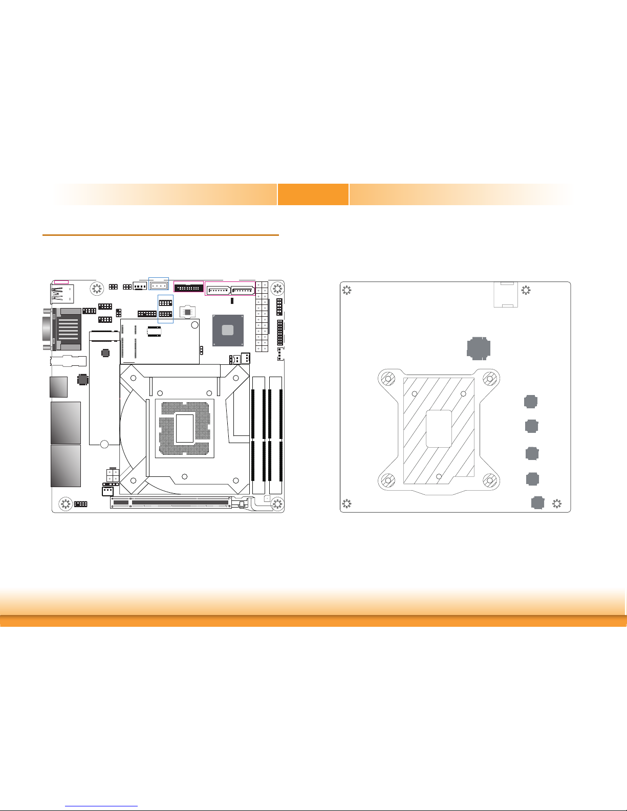
Board Layout
Mini PCIe/mSATA
1
210
9
dTPM 2.0 (opt.)
11
101
1
SATA 3
LAN 3-4
COM1
VGA
USB 3.0
USB 2.0
PCIe 1 (PCIe x16)
Intel
H110
1
LPC
1
13
2
14
131
ATX Power
1
1
Battery
+12V
Power
1
2
43
CH7517 4
3
DDR4_2 SODIMM
DDR4_1 SODIMM
USB 7-8
USB 5-6
10
9
1
2
10
9
1
2
COM 2
COM 3
COM 4
2
165
2
1
6
5
SPI
Flash
BIOS
Digital I/O
Power
12
1112
Front
Panel
1
Mini PCIe/mSATA
Signal Select
(JP9)
1
System
Fan 1
1
Clear CMOS
(JP4)
1
System Fan 2
S/PDIF
1
1
2
5
6
SMBus
1
CPU Fan
ASM1442
Standby
Power LED
4
5
3
2
20
19
1
Digital I/O
12 24
SATA 3.0
SATA 2
Buzzer
2
3
3
COM 3
RS232/Power
Select (JP17)
COM 4
RS232/Power
Select (JP24)
10
9
1
2
10
9
1
2
USB 3-4
10
91
2
M.2 M Key
LAN 1-2
Front Audio
USB 1-2
USB 3.0
COM 1
VGA
DP++
HDMI
USB 9
Socket LGA1151
Bottom ViewTop View
Realtek
ALC888S-VD2-GR
(Realtek ALC262 opt.)
SIM Slot
NCT6106D
Intel I210AT
or I211AT (opt.)
Intel I210AT
or I211AT (opt.)
Intel I210AT
or I211AT (opt.)
Intel I210AT
or I211AT (opt.)
Page 10
www.dfi .com
10
Chapter 2 Hardware Installation
Chapter 2
COM1
VGA
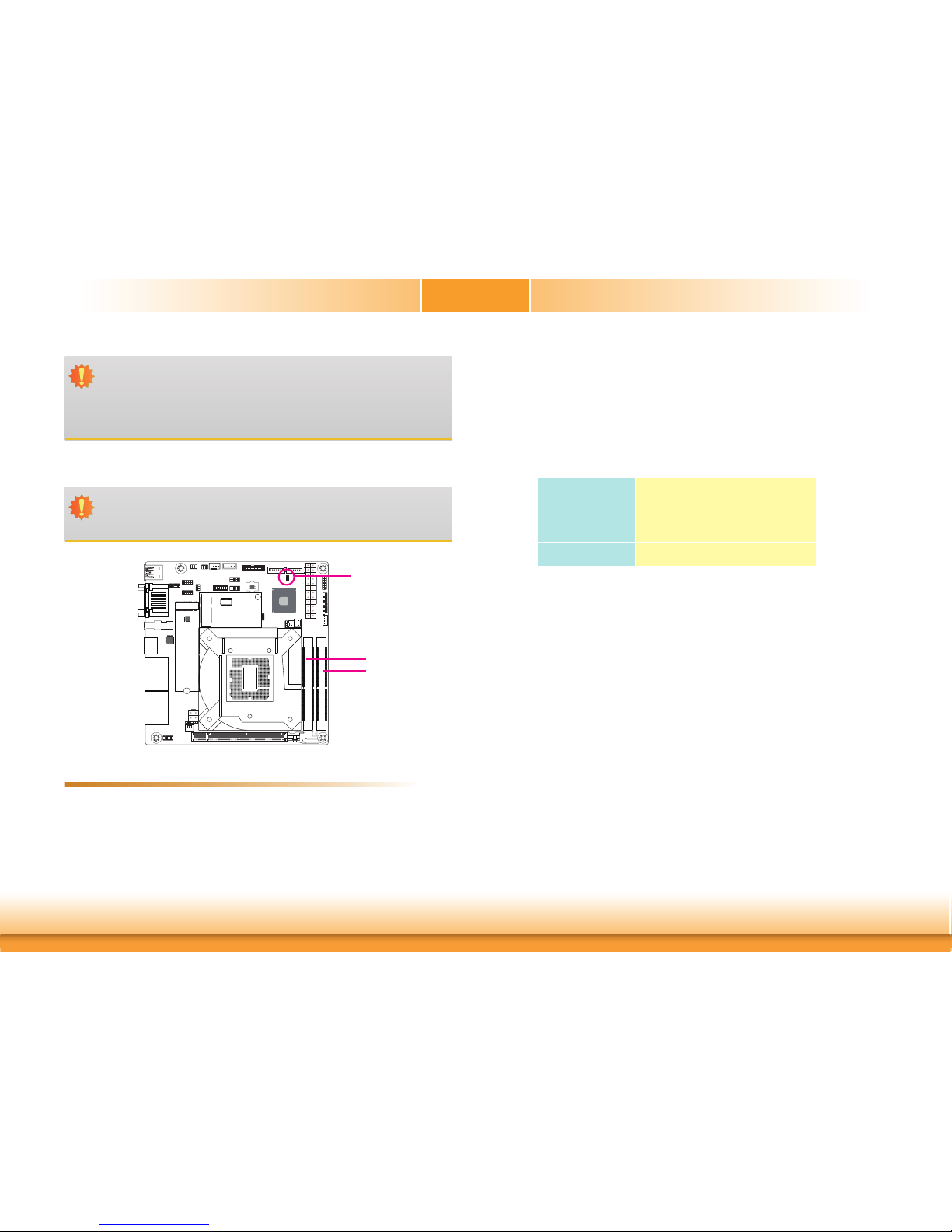
System Memory
DDR4_2
DDR4_1
Features
• Two 260-pin SODIMM up to 32GB
• Dual Channel DDR4 1866/2133MHz
Important:
Electrostatic discharge (ESD) can damage your board, processor, disk drives, add-in
boards, and other components. Perform installation procedures at an ESD workstation
only. If such a station is not available, you can provide some ESD protection by wearing an antistatic wrist strap and attaching it to a metal part of the system chassis. If
a wrist strap is unavailable, establish and maintain contact with the system chassis
throughout any procedures requiring ESD protection.
Important:
When the Standby Power LED lights red, it indicates that there is power on the
system board. Power-off the PC then unplug the power cord prior to installing any devices. Failure to do so will cause severe damage to the motherboard and components.
Standby Power LED
The system board supports the following memory interface.
Single Channel (SC)
Data will be accessed in chunks of 64 bits (8B) from the memory channels.
Dual Channel (DC)
Data will be accessed in chunks of 128 bits from the memory channels. Dual channel provides
better system performance because it doubles the data transfer rate.
Single Channel
DIMMs are on the same channel.
DIMMs in a channel can be identical or
completely different. However, we highly
recommend using identical DIMMs.
Not all slots need to be populated.
Dual Channel
DIMMs of the same memory configuration
are on different channels.
Page 11
www.dfi .com
11
Chapter 2 Hardware Installation
Chapter 2
Installing the SODIMM Module
Note:
The system board used in the following illustrations may not resemble the actual
board. These illustrations are for reference only.
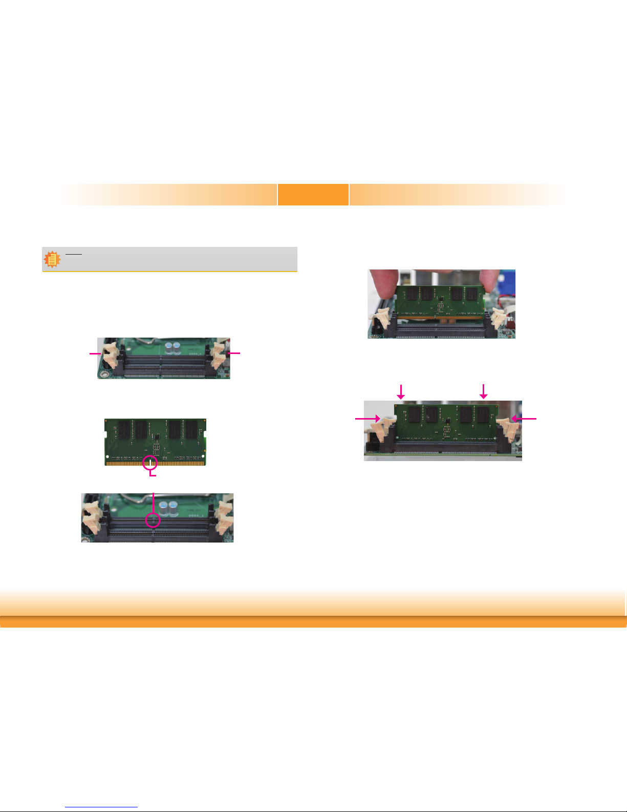
1. Make sure the PC and all other peripheral devices connected to it has been powered down.
2. Disconnect all power cords and cables.
3. Locate the SODIMM socket on the system board.
4. Push the “ejector tabs” which are at the ends of the socket to the side.
Ejector tab
Ejector tab
5. Note how the module is keyed to the socket.
Key
Notch
7. Seat the module vertically, pressing it down firmly until it is completely seated in the
socket. The ejector tabs at the ends of the socket will automatically snap into the locked
position to hold the module in place.
6. Grasping the module by its edges, position the module above the socket with the “notch”
in the module aligned with the “key” on the socket. The keying mechanism ensures the
module can be plugged into the socket in only one way.
Page 12
www.dfi .com
12
Chapter 2 Hardware Installation
Chapter 2
CPU
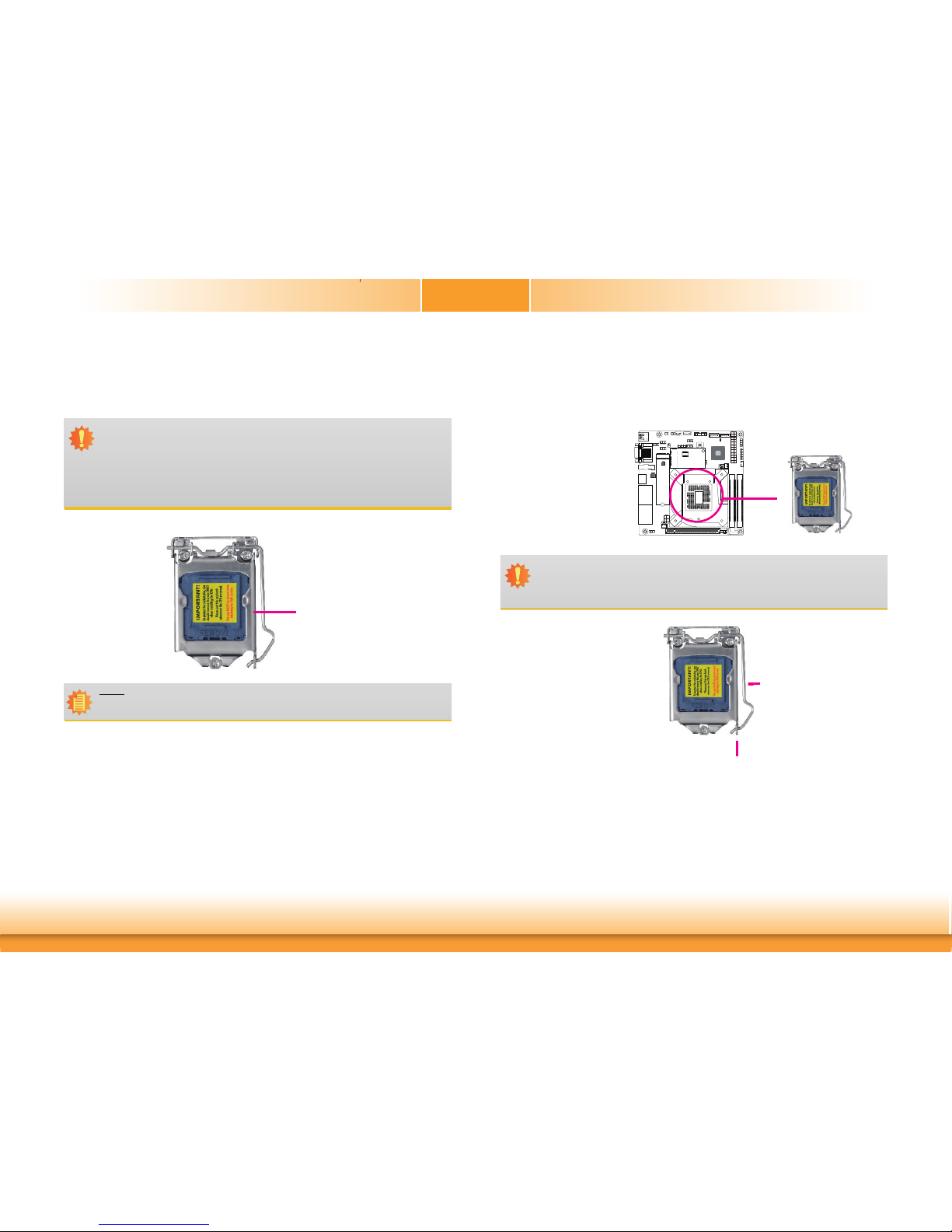
The system board is equipped with a surface mount LGA 1151 socket. This socket is exclusively designed for installing a LGA 1151 packaged Intel CPU.
Protective
cap
Important:
1. Before you proceed, make sure (1) the LGA 1151 socket comes with a protective
cap, (2) the cap is not damaged and (3) the socket’s contact pins are not bent. If
the cap is missing or the cap and/or contact pins are damaged, contact your dealer
immediately.
2. Make sure to keep the protective cap. RMA requests will be accepted and processed only if the LGA 1151 socket comes with the protective cap.
Note:
The system board used in the following illustrations may not resemble the actual
board. These illustrations are for reference only.
Important:
The CPU socket must not come in contact with anything other than the CPU. Avoid
unnecessary exposure. Remove the protective cap only when you are about to install
the CPU.
COM1
VGA
Installing the CPU
1. Make sure the PC and all other peripheral devices connected to it has been powered down.
2. Disconnect all power cords and cables.
3. Locate the LGA 1151 CPU
socket on the system
board.
4. Unlock the socket by pushing the load lever down,
moving it sideways until it
is released from the retention tab; then lift the load
lever up.
Retention tab
Load lever
Page 13

www.dfi .com
13
Chapter 2 Hardware Installation
Chapter 2
6. Remove the protective cap
from the CPU socket. The
cap is used to protect the
CPU socket against dust
and harmful particles.
Remove the protective cap
only when you are about
to install the CPU.
Load lever
Load
plate
5. Lifting the load lever will at
the same time lift the load
plate.
Lift the load lever up to
the angle shown on the
photo.
Protective cap
Important:
The CPU will fit in only one orientation and can easily be inserted without exerting
any force.
7. Insert the CPU into the
socket. The gold triangular
mark on the CPU must
align with the corner of
the CPU socket shown on
the photo.
The CPU’s notch will at
the same time fit into the
socket’s alignment key.
Alignment key
Alignment key
Gold triangular mark
Page 14
www.dfi .com
14
Chapter 2 Hardware Installation
Chapter 2
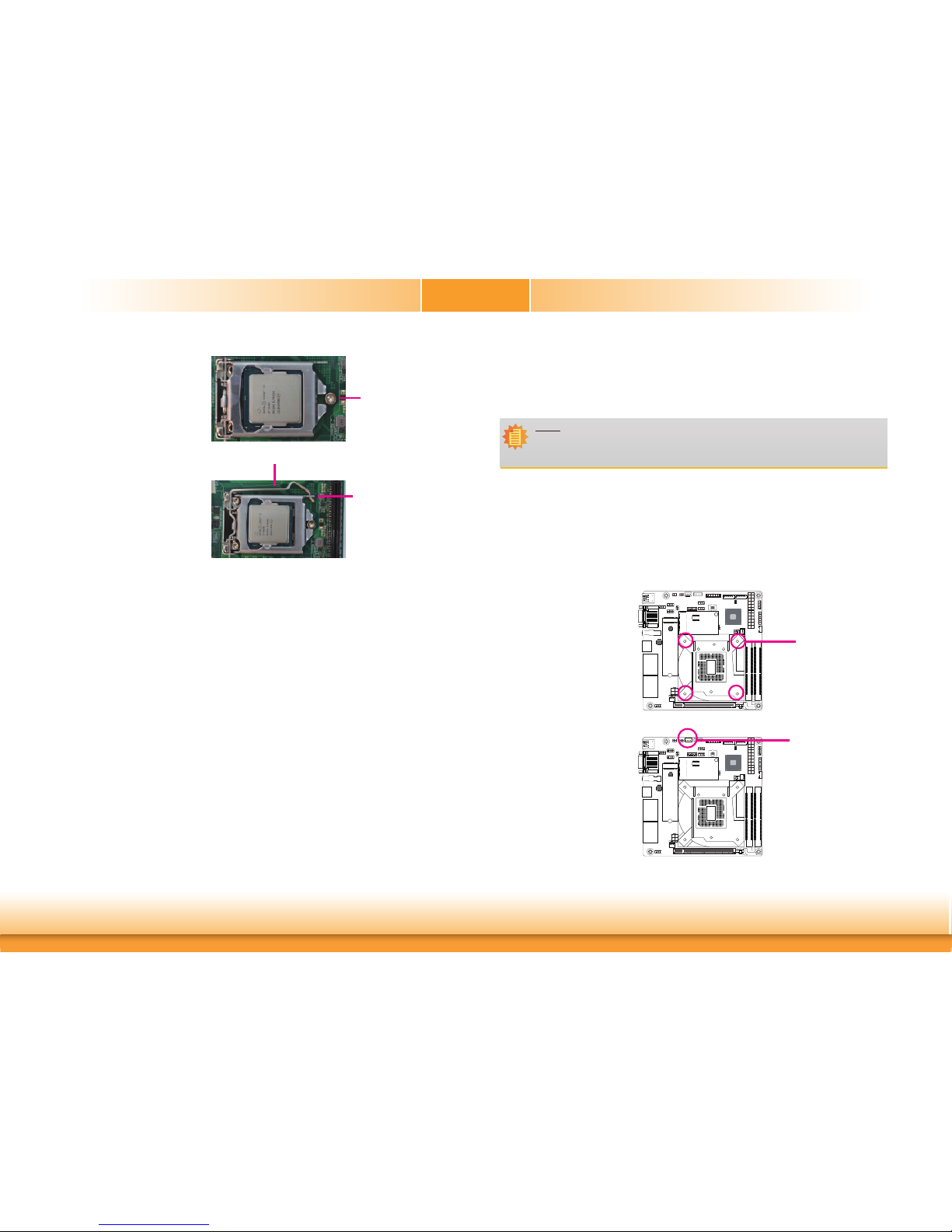
8. Close the load plate then
push the load lever down.
While closing the load
plate, make sure the front
edge of the load plate
slides under the retention
knob.
Retention knob
9. Hook the load lever under
the retention tab.
Load lever
Retention tab
COM1
VGA
COM1
VGA
Installing the Fan and Heat Sink
The CPU must be kept cool by using a CPU fan with heat sink. Without sufficient air circulation across the CPU and heat sink, the CPU will overheat damaging both the CPU and system
board.
1. Before you install the fan / heat sink, you must apply a thermal paste onto the top of the
CPU. The thermal paste is usually supplied when you purchase the fan / heat sink assembly. Do not spread the paste all over the surface. When you later place the heat sink on
top of the CPU, the compound will disperse evenly.
Some heat sinks come with a patch of pre-applied thermal paste. Do not apply thermal
paste if the fan / heat sink already has a patch of thermal paste on its underside. Peel the
strip that covers the paste before you place the fan / heat sink on top of the CPU.
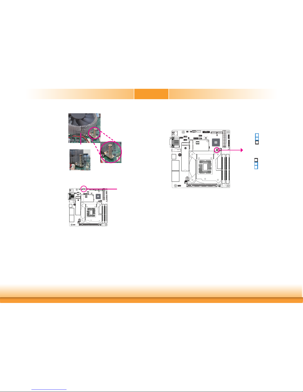
2. Place the heat sink on top
of the CPU. The 4 screw
around the heat sink,
which are used to secure
the heat sink onto the system board, must match the
4 mounting holes around
the socket.
Mounting hole
3. Orient the heat sink such
that the CPU fan’s cable is
nearest the CPU fan connector.
CPU fan connector
Note:
A boxed Intel® processor already includes the CPU fan and heat sink assembly. If your
CPU was purchased separately, make sure to only use Intel
®
-certified fan and heat
sink.
Page 15
www.dfi .com
15
Chapter 2 Hardware Installation
Chapter 2
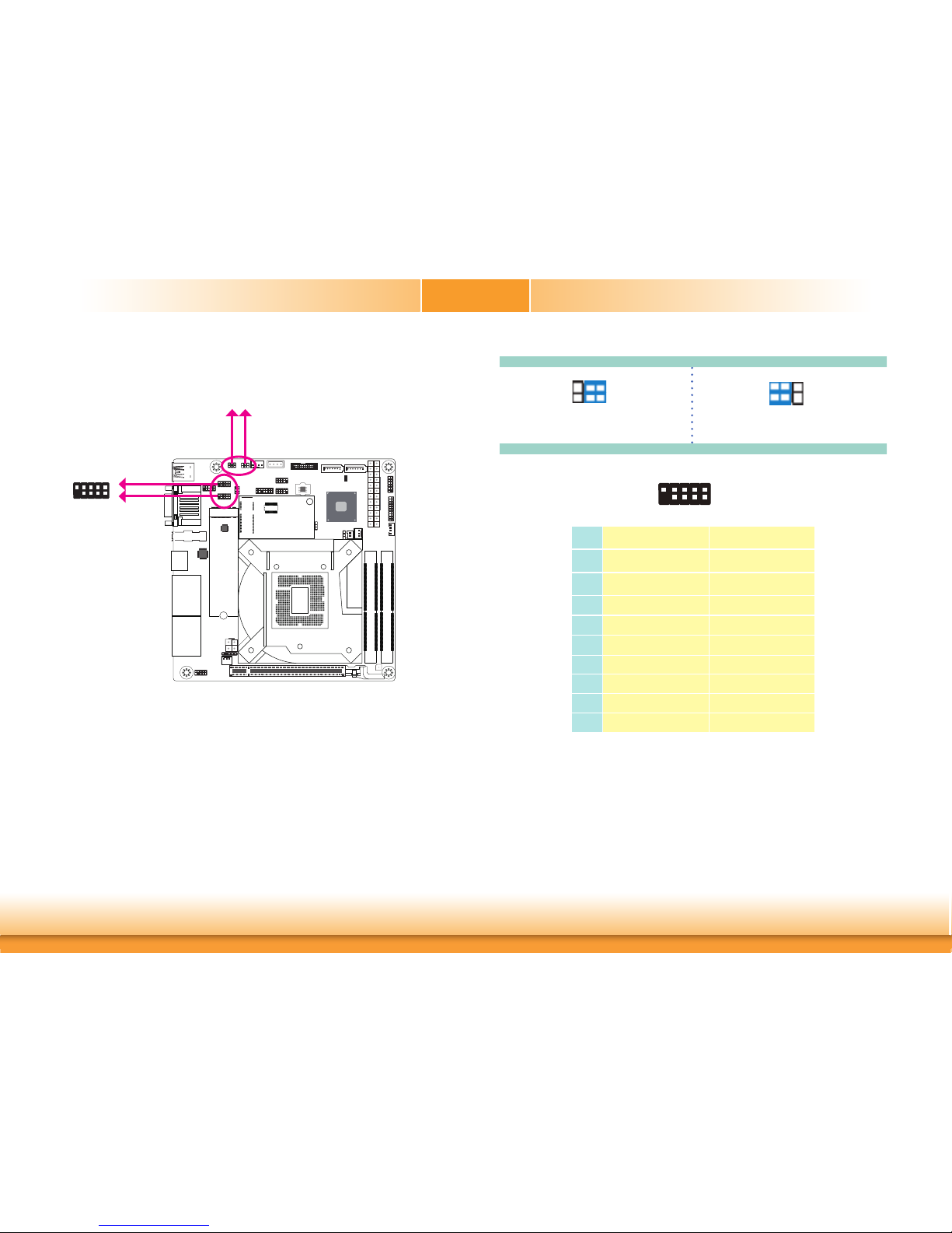
4. Rotate each screw that are
diagonally across the heat
sink. Perform the same
procedure for the other
screws.
Heat sink
“Locked” position of
screw
5. Connect the CPU fan’s
cable to the CPU fan
connector on the system
board.
“Unlocked” position
of screw
COM1
VGA
CPU fan connector
COM1
VGA
Jumper Settings
Clear CMOS
If you encounter the followings,
a) CMOS data becomes corrupted.
b) You forgot the supervisor or user password.
you can reconfigure the system with the default values stored in the ROM BIOS.
To load the default values stored in the ROM BIOS, please follow the steps below.
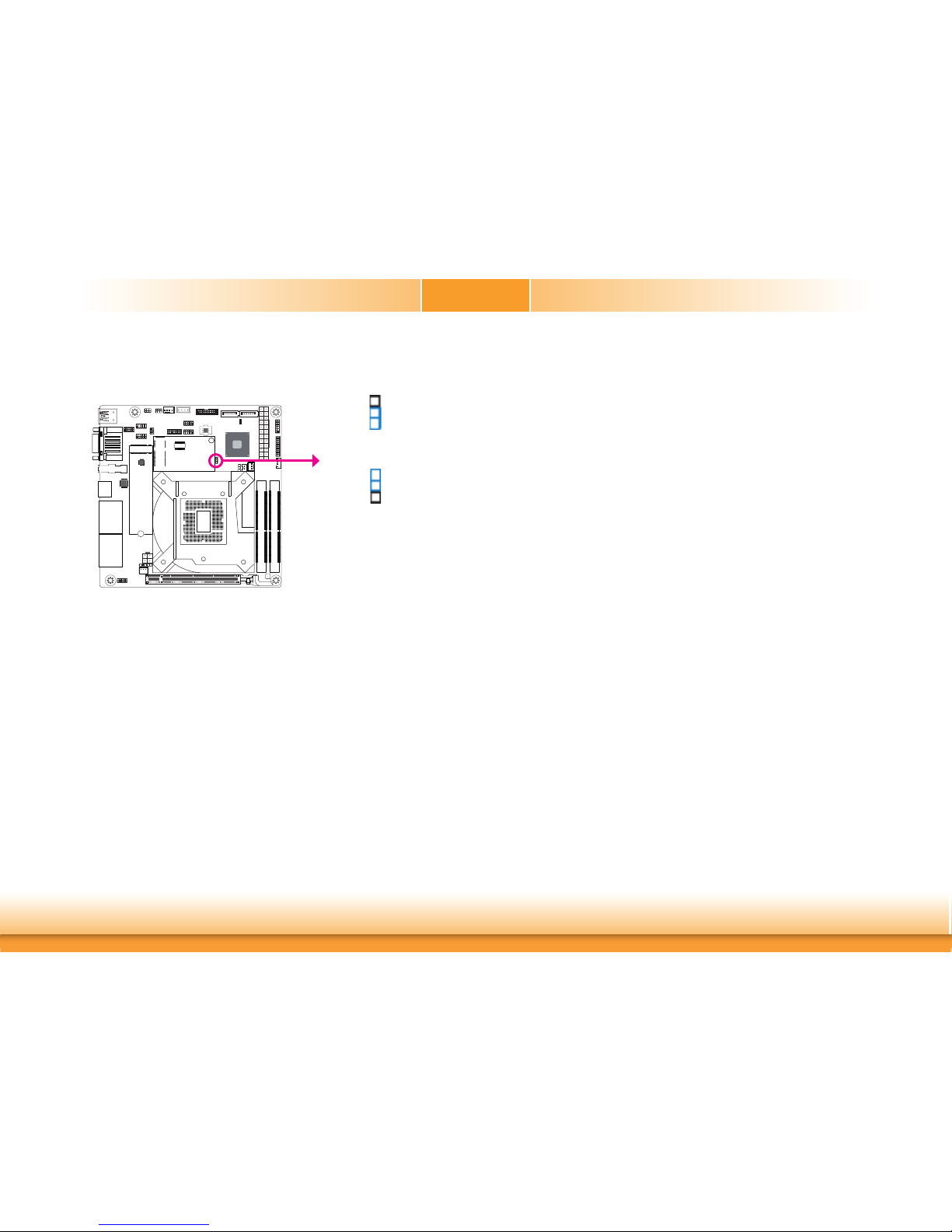
1. Power-off the system and unplug the power cord.
2. Set JP4 pins 2 and 3 to On. Wait for a few seconds and set JP4 back to its default setting,
pins 1 and 2 On.
3. Now plug the power cord and power-on the system.
JP4
2-3 On:
Clear CMOS
1-2 On:
Normal (default)
3
1
2
3
1
2
Page 16
www.dfi .com
16
Chapter 2 Hardware Installation
Chapter 2
JP17 (for COM 3) and JP24 (for COM 4) are used to configure Serial COM ports to pure RS232
or RS232 with power. The pin functions of COM 3 and COM 4 will vary according to JP17’s and
JP24’s setting respectively.
COM 3
COM1
VGA
JP17
(for COM 3)
JP24
(for COM 4)
COM 4
1
2
9
10
COM3/COM4 RS232/Power Select
COM 3/COM 4
Pin RS232 RS232 with power
1
DCD- +12V
2
RXD RXD
3
TXD TXD
4
DTR- DTR-
5
GND GND
6
DSR- DSR-
7
RTS- RTS-
8
CTS- CTS-
9
RI- +5V
JP17 (for COM 3)/JP24 (for COM 4)
1-3 (RI-), 2-4 (DCD-) On:
RS232 (default)
3-5 (+5V), 4-6 (+12V) On:
RS232 with power
5 3 1
6
4
2
5 3
1
64
2
2
19
Page 17
www.dfi .com
17
Chapter 2 Hardware Installation
Chapter 2
Mini PCIe/mSATA Signal Select
JP9
JP9 is used to select the Mini PCIe/mSATA signal.
COM1
VGA
2-3 On:
Mini PCIe
1-2 On:
mSATA (default)
1
3
2
1
3
2
Page 18
www.dfi .com
18
Chapter 2 Hardware Installation
Chapter 2
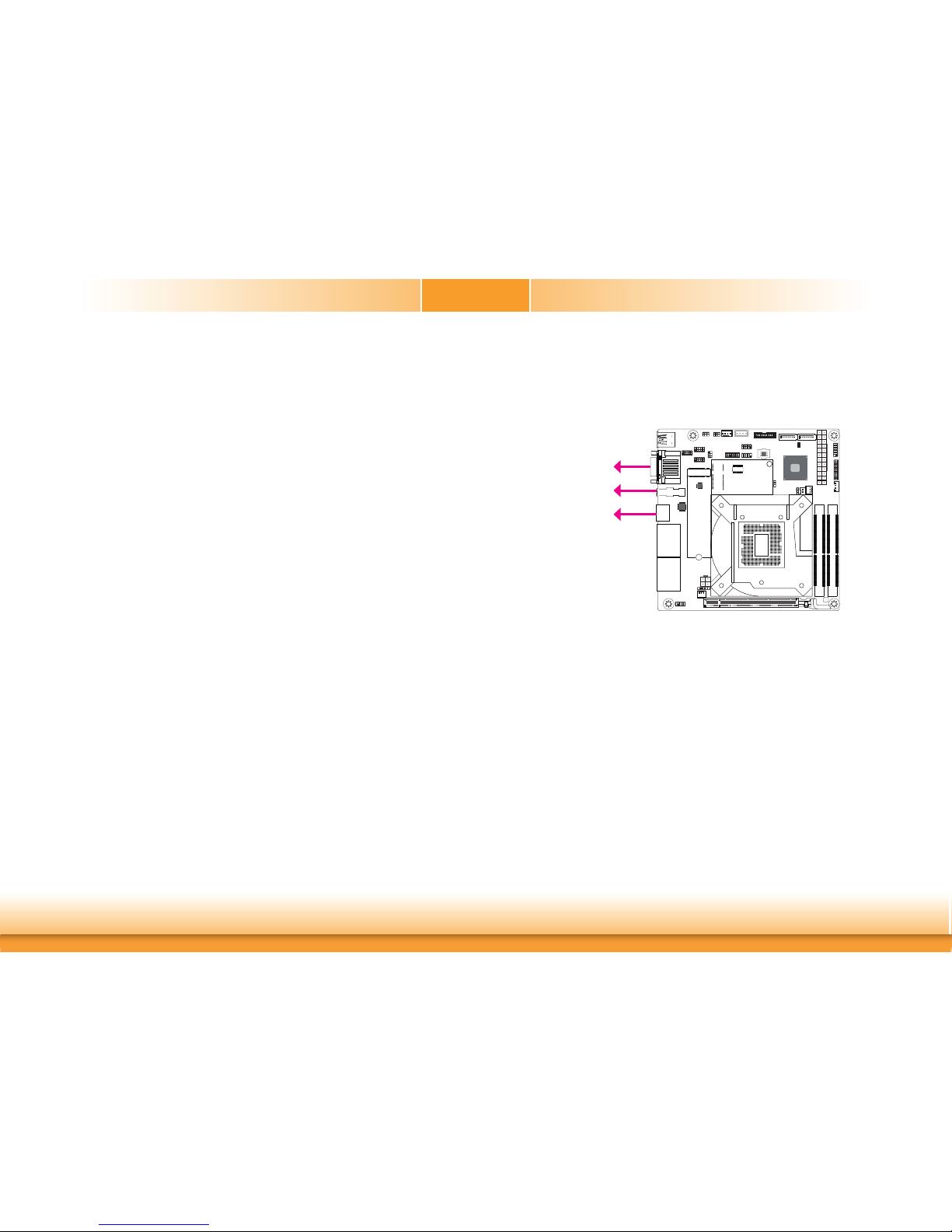
Rear Panel I/O Ports
The rear panel I/O ports consist of the following:
• 2 x USB 3.0
• 1 x RS-232/422/485 (DB-9)
• 1 x VGA
• 1 x DP++
• 1 x HDMI 1.4
• 4 x GbE (RJ-45)
Graphics Interfaces
VGA Port
The VGA port is used for connecting a VGA monitor. Connect the monitor’s 15-pin D-shell cable
connector to the VGA port. After you plug the monitor’s cable connector into the VGA port,
gently tighten the cable screws to hold the connector in place.
DP++ Port
The DisplayPort is a digital display interface used to connect a display device such as a computer monitor. It is used to transmit audio and video simultaneously. The interface, which is
developed by VESA, delivers higher performance features than any other digital interface.
HDMI 1.4 Port
The HDMI port which carries both digital audio and video signals is used to connect a LCD
monitor or digital TV that has the HDMI port.
Driver Installation
Install the graphics driver. Refer to chapter 4 for more information.
The display ports consist of the following:
• 1 VGA port
• 1 DP++ port
• 1 HDMI 1.4 port
HDMI 1.4
VGA
COM1
VGA
DP++
Page 19
www.dfi .com
19
Chapter 2 Hardware Installation
Chapter 2
Important:
If you are using the Wake-On-USB Keyboard/Mouse function for 2 USB ports, the
+5V_standby power source of your power supply must support ≥1.5A. For 3 or more
USB ports, the +5V_standby power source of your power supply must support ≥2A.
Wake-On-USB Keyboard/Mouse
The Wake-On-USB Keyboard/Mouse function allows you to use a USB keyboard or USB mouse
to wake up a system from the S3 (STR - Suspend To RAM) state.
BIOS Setting
Configure these onboard USB devices in the Advanced menu (“USB Configuration” submenu)
of the BIOS. Refer to the chapter 3 for more information.
Driver Installation
You may need to install the proper drivers in your system operation to use the USB device.
Refer to your operating system’s manual or documentation for more information.
USB Ports
USB 7-8
10
9
1
2
USB 2.0
COM1
VGA
USB 1
USB 2
USB 3.0
USB 5-6
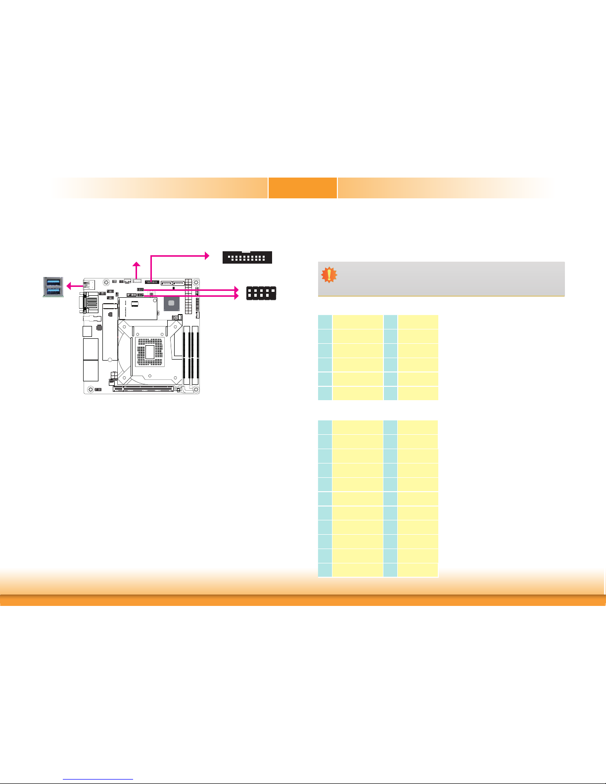
The USB device allows data exchange between your computer and a wide range of simultaneously accessible external Plug and Play peripherals.
The system board is equipped with 2 onboard USB 3.0 ports (USB 1-2). The 10-pin connectors
allow you to connect 4 additional USB 2.0 ports (USB 5-6/7-8). The 20-pin connector allows
you to connect 2 additional USB 3.0 ports (USB 3-4).The additional USB ports may be mounted on a card-edge bracket. Install the card-edge bracket to an available slot at the rear of the
system chassis and then insert the USB port cables to a connector.
Vertical USB 9
USB 2.0
Pin Assignment Pin Assignment
1
PWR 2 PWR
3 DATA- 4 D ATA-
5 DATA+ 6 D ATA+
7 GND 8 GND
9 --- 10 NC
USB 2.0 5-6/7-8 Headers
USB 3-4
USB 3.0
1
20
10
11
Pin Assignment Pin Assignment
1
PWR 20 ---
2 RX- 19 PWR
3 RX+ 18 RX-
4 GND 17 RX+
5 TX- 16 GND
6 TX+ 15 TX-
7 GND 14 TX+
8 DATA- 13 GND
9 DATA+ 12 DATA-
10 NC 11 DATA +
USB 3.0 3-4 Header
Page 20
www.dfi .com
20
Chapter 2 Hardware Installation
Chapter 2
COM1
VGA
COM (Serial) Ports
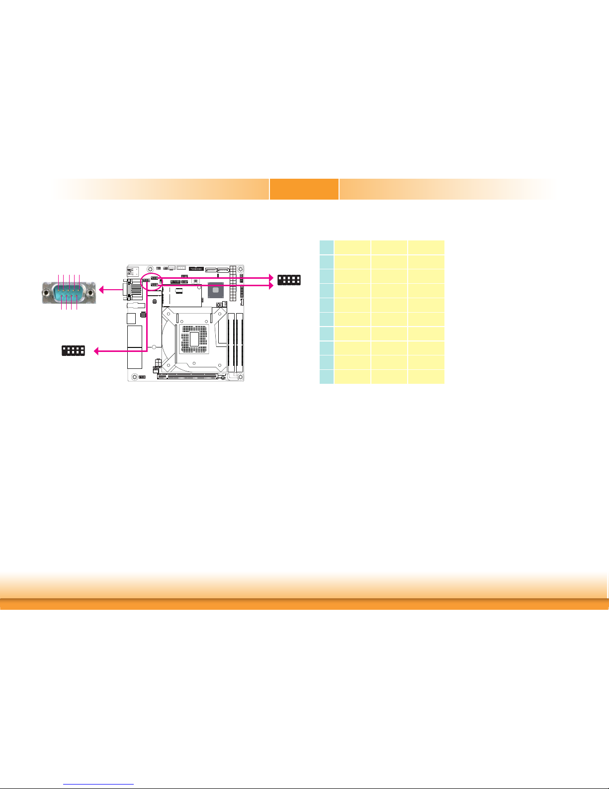
COM 1 and COM 2 can be selected among RS232, RS422 and RS485 via the BIOS setup utility.
Please refer to the pin functions at right.
The pin functions of COM 3 and COM 4 will vary according to JP17’s and JP24’s setting. JP17
and JP24 allow you to configure COM 3 and COM 4 to RS232 or RS232 with power. Refer to
“COM3/COM4 RS232/Power Select” in this chapter for more information.
The serial ports are asynchronous communication ports with 16C550A-compatible UARTs that
can be used with modems, serial printers, remote display terminals, and other serial devices.
Connecting External Serial Ports
Your COM port may come mounted on a card-edge bracket. Install the card-edge bracket to
an available slot at the rear of the system chassis then insert the serial port cable to the COM
connector. Make sure the colored stripe on the ribbon cable is aligned with pin 1 of the COM
connector.
BIOS Setting
Configure the COM ports 1/2/3/4 in the Advanced menu (“SIO NUVOTON6106D” submenu) of
the BIOS. Refer to the chapter 3 for more information.
6789
1
2345
COM 3/4:
RS232/RS232 with power
1
2
9
10
COM 1/2: RS232/422/485
COM 1
COM 2
COM 3
COM 4
1
2
9
10
COM 1 Port/COM 2 Header
Pin RS232
RS422
Full Duplex
RS485
1
DCD- TX- DATA-
2 RXD TX+ DATA+
3 TXD RX+ NC
4 DTR- RX- NC
5 GND GND GND
6 DSR- NC NC
7 RTS- NC NC
8 CTS- NC NC
9 RI- NC NC
Page 21
www.dfi .com
21
Chapter 2 Hardware Installation
Chapter 2
RJ45 LAN Ports
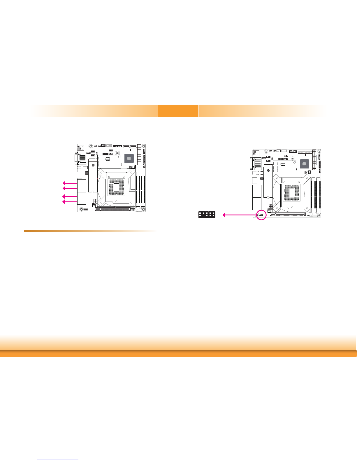
The LAN ports allow the system board to connect to a local area network by means of a
network hub.
BIOS Setting
Configure the onboard LAN ports in the Advanced menu (“ACPI Configuration” submenu) of
the BIOS. Refer to the chapter 3 for more information.
Driver Installation
Install the LAN drivers. Refer to the chapter 4 for more information.
Features
• 4 Intel® I210AT PCIe or Intel® I211AT PCIe
COM1
VGA
LAN 2
LAN 1
LAN 4
LAN 3
I/O Connectors
Front Audio Connector
Front Audio
The front audio connector allows you to connect to the line-out and mic-in jacks that are at
the front panel of your system.
BIOS Setting
Configure these Audio devices in the Advanced menu (“Audio Configuration” submenu) of the
BIOS. Refer to the chapter 3 for more information.
Driver Installation
Install the audio driver. Refer to the chapter 4 for more information.
Front Audio
1
Mic2-L
Line2-R
GND
GND
NC
2
9
Mic2-JD
Line2-JD
10
Mic2-R
Line2-L
COM1
VGA
Page 22
www.dfi .com
22
Chapter 2 Hardware Installation
Chapter 2
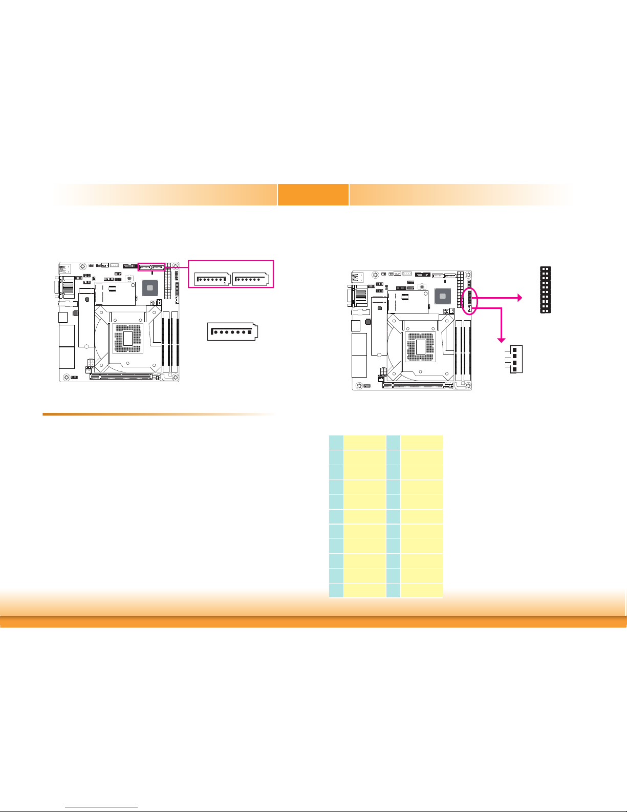
SATA (Serial ATA) Connectors
COM1
VGA
SATA 3.0 6Gb/s
SATA 2
7
RX-
GND
TX+
TX-
GND
RX+
GND
• 2 Serial ATA 3.0 ports with data transfer rate up to 6Gb/s (SATA 2 and SATA 3)
The Serial ATA connectors are used to connect Serial ATA devices. Connect one end of the Serial ATA data cable to a SATA connector and the other end to your Serial ATA device.
BIOS Setting
Configure the Serial ATA drives in the Advanced menu (“SATA Configuration” submenu) of the
BIOS. Refer to the chapter 3 for more information.
Features
The 16-bit Digital I/O connector provides powering-on function to external devices that are
connected to this connector.
1
4
+12V
GND
5VDU
5V
Digital I/O Power
Digital I/O
Digital I/O Connector
Digital I/O Power Connector
Digital I/O Connector
COM1
VGA
SATA 3
1
20
19
21
Pin Assignment Pin Assignment
1
DIO0 2 DIO8
3 DIO1 4 DIO9
5 DIO2 6 DIO10
7 DIO3 8 DIO11
9 DIO4 10 DIO12
11 DIO5 12 DIO13
13 DIO6 14 DIO14
15 DIO7 16 DIO15
17 GND 18 GND
19 GND 20 GND
Page 23
www.dfi .com
23
Chapter 2 Hardware Installation
Chapter 2
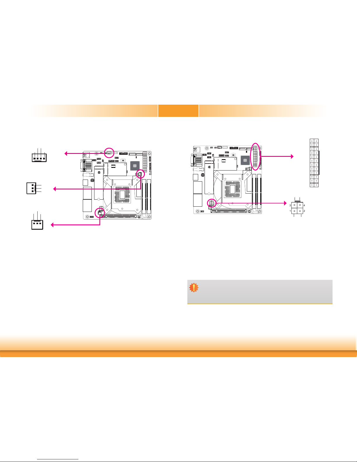
Cooling Fan Connectors
The fan connectors are used to connect cooling fans. The cooling fans will provide adequate
airflow throughout the chassis to prevent overheating the CPU and system board components.
BIOS Setting
The Advanced menu (“SIO NUVOTON6106D” submenu) of the BIOS will display the current
speed of the cooling fans. Refer to the chapter 3 for more information.
System Fan 2
Sense
PWR
GND
COM1
VGA
41
Sense+12V
GND
Speed Control
CPU Fan
Power Connectors
Use a power supply that complies with the ATX12V Power Supply Design Guide Version 1.1.
An ATX12V power supply unit has a standard 24-pin ATX main power connector that must be
inserted into the 24-pin connector. The 4-pin +12V power connector enables the delivery of
more +12VDC current to the processor’s Voltage Regulator Module (VRM).
The power connectors from the power supply unit are designed to fit the 24-pin and 4-pin
connectors in only one orientation. Make sure to find the proper orientation before plugging
the connectors.
The system board requires a minimum of 300 Watt power supply to operate. Your system
configuration (CPU power, amount of memory, add-in cards, peripherals, etc.) may exceed the
minimum power requirement. To ensure that adequate power is provided, we strongly recommend that you use a minimum of 400 Watt (or greater) power supply.
Important:
Insufficient power supplied to the system may result in instability or the add-in boards
and peripherals not functioning properly. Calculating the system’s approximate power
usage is important to ensure that the power supply meets the system’s consumption
requirements.
ATX power
+12V Power
COM1
VGA
13
12 24
1
+3.3V
+3.3V
GND
+5V
GND
+5V
GND
PWR_OK
+5VSB
+12V
+12V
+3.3V
+3.3V
-12V
GND
PS_ON#
GND
GND
GND
NC
+5V
+5V
+5V
GND
1
Ground
Ground
+12V +12V
System Fan 1
1
Sense
PWR
GND
Page 24
www.dfi .com
24
Chapter 2 Hardware Installation
Chapter 2
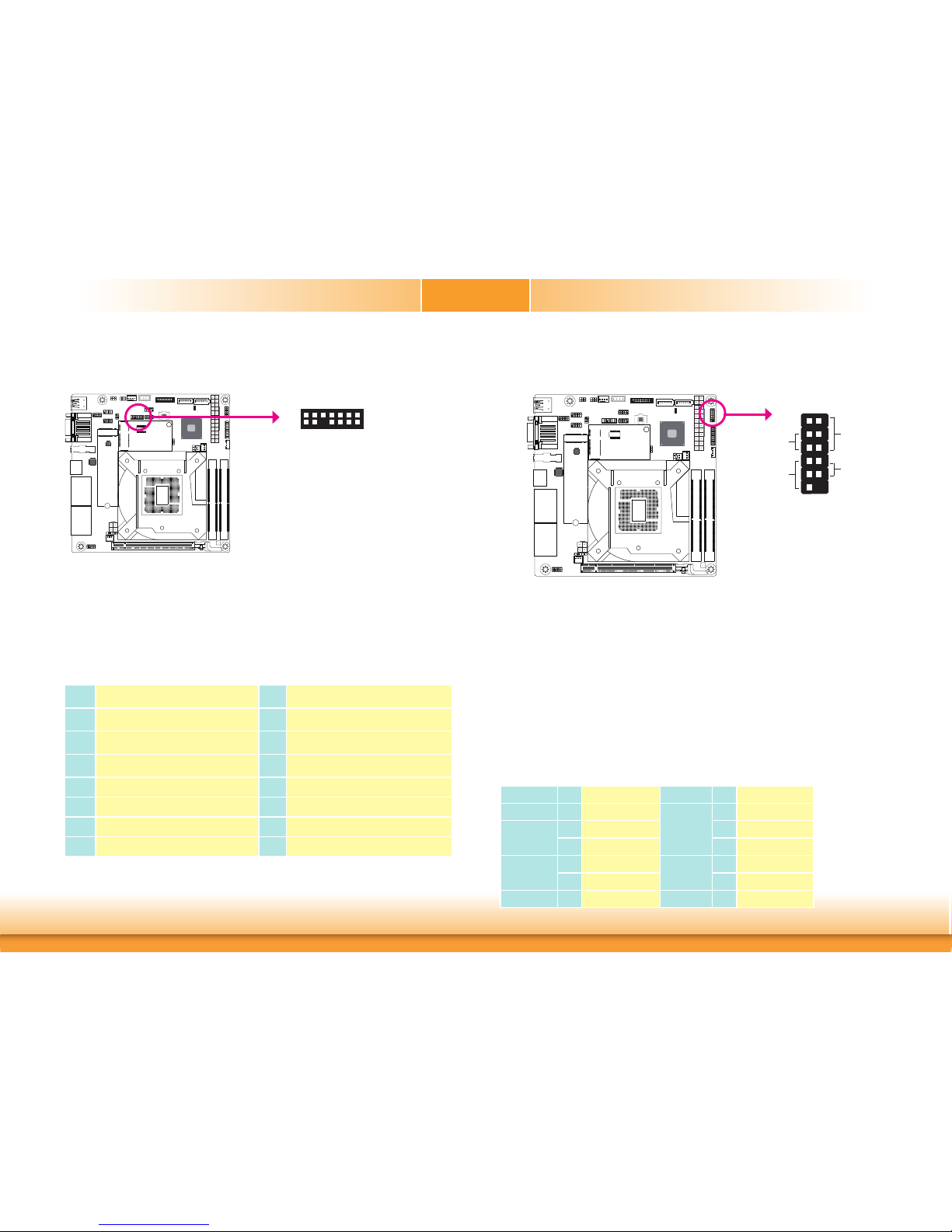
Front Panel Connector
COM1
VGA
HD-LED
RESET
PWR-LED
ATX- SW
1211
2
1
Front
Panel
HD-LED - Hard Drive LED
This LED will light when the hard drive is being accessed.
RESET - Reset Switch
This switch allows you to reboot without having to power off the system.
PWR-LED - Power/Standby LED
When the system’s power is on, this LED will light. When the system is in the S1 (POS - Power
On Suspend) state, it will blink every second. When the system is in the S3 (STR - Suspend To
RAM) state, it will blink every 4 seconds.
ATX-SW - ATX Power Switch
This switch is used to power on or off the system.
Pin Assignment Pin Assignment
1NC
PWR-LED
2 LED Power
HD-LED
3 HDD Power 4 LED Power
5 Signal 6 Signal
RESET
7 GND
ATX-SW
8 GND
9 Signal 10 Signal
11 NC 12 ---
LPC Connector
The Low Pin Count Interface was defined by Intel® Corporation to facilitate the industry’s transition towards legacy free systems. It allows the integration of low-bandwidth legacy I/O components within the system, which are typically provided by a Super I/O controller. Furthermore,
it can be used to interface firmware hubs, Trusted Platform Module (TPM) devices and embedded controller solutions. Data transfer on the LPC bus is implemented over a 4 bit serialized
data interface, which uses a 33MHz LPC bus clock. For more information about LPC bus refer
to the Intel
®
Low Pin Count Interface Specification Revision 1.1’. The table below indicates the
pin fuctions of the LPC connector.
COM1
VGA
LPC
2
1
14
13
Pin Assignment Pin Assignment
1
L_CLK
2
L_AD1
3
L_RST#
4
L_AD0
5
L_FRAME#
6
3V3
7
L_AD3
8
GND
9
L_AD2
10
---
11
INT_SERIRQ
12
GND
13
5VSB
14
5V
Page 25
www.dfi .com
25
Chapter 2 Hardware Installation
Chapter 2
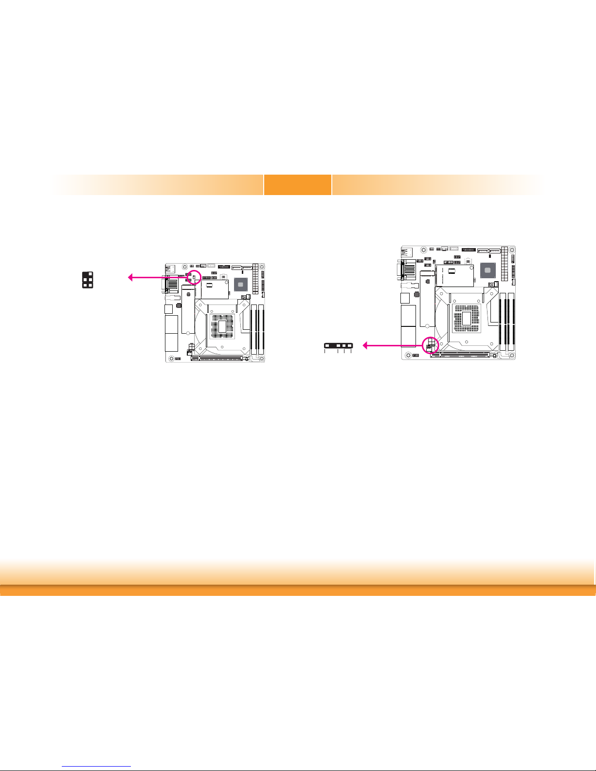
S/PDIF Connector
The S/PDIF connector is used to connect an external S/PDIF port. Your S/PDIF port may be
mounted on a card-edge bracket. Install the card-edge bracket to an available slot at the rear
of the system chassis then connect the audio cable to the S/PDIF connector. Make sure pin 1
of the audio cable is aligned with pin 1 of the S/PDIF connector.
1
5
+5V
SPDIF OUT
GND
SPDIF IN
COM1
VGA
S/PDIF
The SMBus (System Management Bus) connector is used to connect SMBus devices. It is a
multiple device bus that allows multiple chips to connect to the same bus and enable each one
to act as a master by initiating data transfer.
SMBus Connector
1
2
5
6
GND
SMB_DATA
SMB_CLK
3VDU
SMB_ALERT
SMBus
COM1
VGA
Page 26
www.dfi .com
26
Chapter 2 Hardware Installation
Chapter 2
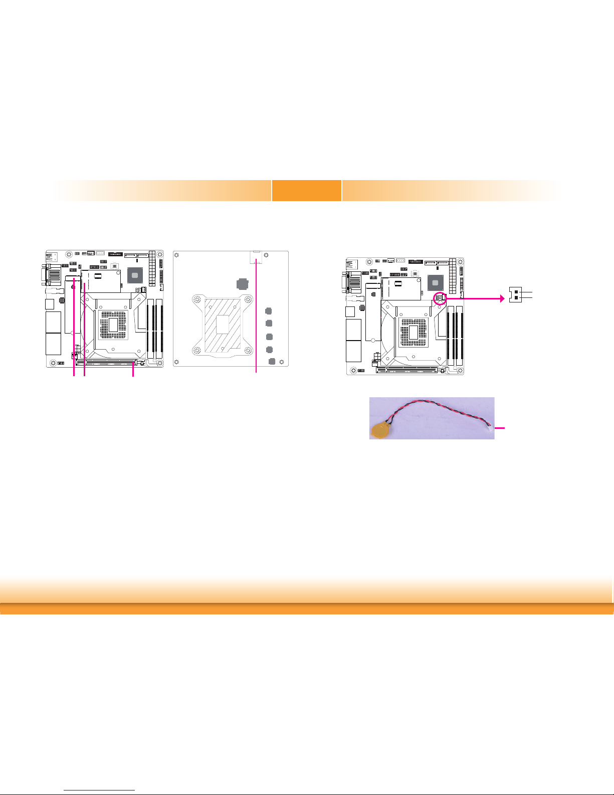
Expansion Slots
PCI Express x16
COM1
VGA
Mini PCI Express
M.2 M Key Socket
The M.2 socket is the Next Generation Form Factor (NGFF) which is designed to support multiple modules and make the M.2 more suitable in application for solid-state storage.
Mini PCI Express Slot
The full-size Mini PCIe socket supports PCIe/mSATA/USB2.0 signals and is used to install a Mini
PCIe card. Mini PCIe and mSATA signals can be switched with a jumper.
PCI Express x16 Slot
Install PCI Express x16 graphics card, that comply to the PCI Express specifications, into the
PCI Express x16 slot. To install a graphics card into the x16 slot, align the graphics card above
the slot then press it down firmly until it is completely seated in the slot. The retaining clip of
the slot will automatically hold the graphics card in place.
SIM Slot
The SIM slot on the system board is used to insert a SIM card.
M.2 M Key
SIM Slot
Battery
The lithium ion battery powers the real-time clock and CMOS memory. It is an auxiliary source
of power when the main power is shut off.
Safety Measures
• Danger of explosion if battery incorrectly replaced.
• Replace only with the same or equivalent type recommended by the manufacturer.
• Dispose of used batteries according to local ordinance
.
Connect to the
battery connector
Battery
Battery
Connector
1
+3.3V
GND
2
COM1
VGA
 Loading...